Notice de fonctionnement - Multimetrix
Notice de fonctionnement - Multimetrix
Notice de fonctionnement - Multimetrix

You also want an ePaper? Increase the reach of your titles
YUMPU automatically turns print PDFs into web optimized ePapers that Google loves.
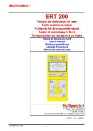
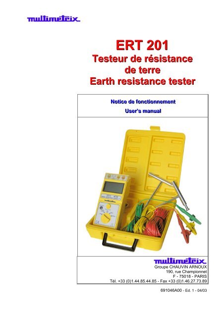
ERT 201<br />
Testeur <strong>de</strong> résistance<br />
<strong>de</strong> terre<br />
Earth resistance tester<br />
Notti ice <strong>de</strong> ffonctti ionnementt<br />
Userr’ ’s manuall<br />
Groupe CHAUVIN ARNOUX<br />
190, rue Championnet<br />
F - 75018 - PARIS<br />
Tél. +33 (0)1.44.85.44.85 - Fax +33 (0)1.46.27.73.89<br />
691046A00 - Ed. 1 - 04/03
Français<br />
Instructions générales<br />
Introduction<br />
Ce testeur a été conçu et testé en accord avec les normes <strong>de</strong> sécurité en<br />
vigueur et notamment IEC 348 et IEC 1010 (EN 61010).<br />
Cependant, nous vous recommandons fortement <strong>de</strong> lire les précautions<br />
d'emploi suivantes.<br />
Précautions et<br />
mesures <strong>de</strong><br />
sécurité<br />
Nous vous conseillons la lecture <strong>de</strong> ce paragraphe avant <strong>de</strong> mettre en<br />
service votre testeur.<br />
Nous rejetons toute responsabilité pour tout dommage causé par une<br />
manipulation ou utilisation non conforme aux instructions <strong>de</strong><br />
<strong>fonctionnement</strong> décrites dans cette notice <strong>de</strong> <strong>fonctionnement</strong>.<br />
Les conditions d'utilisation sont les suivantes :<br />
• utilisation en intérieur<br />
• sur une installation Catégorie III 300 V<br />
• <strong>de</strong>gré <strong>de</strong> pollution 2<br />
• jusqu'à 2000 m d'altitu<strong>de</strong><br />
• humidité relative max : 80 %<br />
• température ambiante : 0 à 40°C<br />
définition <strong>de</strong>s<br />
catégories<br />
d’installation<br />
(cf. CEI 664-1)<br />
CAT I : Les circuits <strong>de</strong> CAT I sont <strong>de</strong>s circuits protégés par <strong>de</strong>s dispositifs<br />
limitant les surtensions transitoires à un faible niveau.<br />
Exemple : circuits électroniques protégés<br />
CAT II : Les circuits <strong>de</strong> CAT II sont <strong>de</strong>s circuits d'alimentation d'appareils<br />
domestiques ou analogues, pouvant comporter <strong>de</strong>s surtensions<br />
transitoires <strong>de</strong> valeur moyenne.<br />
Exemple : alimentation d'appareils ménagers et d'outillage portable<br />
CAT III :Les circuits <strong>de</strong> CAT III sont <strong>de</strong>s circuits d'alimentation d'appareils<br />
<strong>de</strong> puissance pouvant comporter <strong>de</strong>s surtensions transitoires<br />
importantes.<br />
Exemple : alimentation <strong>de</strong> machines ou appareils industriels<br />
CAT IV :Les circuits <strong>de</strong> CAT IV sont <strong>de</strong>s circuits pouvant comporter <strong>de</strong>s<br />
surtensions transitoires très importantes.<br />
Exemple : arrivées d'énergie<br />
Symboles<br />
électriques<br />
internationaux<br />
Appareil protégé par une double isolation ou isolation renforcée<br />
Danger ! Risque <strong>de</strong> choc électrique<br />
Attention! Se référer aux précautions d'emploi avant utilisation<br />
2 Testeur <strong>de</strong> résistance <strong>de</strong> terre
Français<br />
Instructions générales (suite)<br />
Garantie<br />
Vérification<br />
métrologique<br />
Entretien<br />
Stockage<br />
ré-<br />
Déballage et<br />
emballage<br />
Ce matériel est garanti contre tout défaut <strong>de</strong> matière ou vice <strong>de</strong> fabrication,<br />
conformément aux conditions générales <strong>de</strong> vente.<br />
Durant la pério<strong>de</strong> <strong>de</strong> garantie (1 an), l'appareil ne peut être réparé que par<br />
le constructeur, celui-ci se réservant la décision <strong>de</strong> procé<strong>de</strong>r soit à la<br />
réparation, soit à l'échange <strong>de</strong> tout ou partie <strong>de</strong> l'appareil. En cas <strong>de</strong> retour<br />
du matériel au constructeur, le transport aller est à la charge du client. La<br />
garantie ne s’applique pas suite à :<br />
1. une utilisation impropre du matériel ou par association <strong>de</strong> celui- ci avec<br />
un équipement incompatible<br />
2. une modification du matériel sans autorisation explicite <strong>de</strong>s services<br />
techniques du constructeur<br />
3. l’intervention effectuée par une personne non agréée par le constructeur<br />
4. l'adaptation à une application particulière, non prévue par la définition du<br />
matériel ou par la notice <strong>de</strong> <strong>fonctionnement</strong><br />
5. un choc, une chute ou une inondation.<br />
Comme tous les appareils <strong>de</strong> mesure ou d'essais, une vérification périodique<br />
est nécessaire.<br />
Renseignements et coordonnées sur <strong>de</strong>man<strong>de</strong> :<br />
Tél. 02.31.64.51.55 - Fax 02.31.64.51.09.<br />
Périodiquement, nettoyer votre testeur avec un tissu humi<strong>de</strong> imprégné<br />
d'eau savonneuse. Ne pas utiliser <strong>de</strong> matières abrasives ou contenant<br />
<strong>de</strong>s solvants.<br />
Si vous n'utilisez pas votre testeur pendant une pério<strong>de</strong> supérieure à<br />
60 jours, retirez les piles et stockez-les séparément.<br />
L’ensemble du matériel a été vérifié mécaniquement et électriquement<br />
avant l’expédition.<br />
Toutefois, il est conseillé <strong>de</strong> procé<strong>de</strong>r à une vérification rapi<strong>de</strong> pour<br />
détecter toute détérioration éventuelle lors du transport. Si tel était le cas,<br />
faites alors immédiatement les réserves d’usage auprès du transporteur.<br />
En cas <strong>de</strong> réexpédition, utilisez l’emballage d’origine et indiquez, par une<br />
note jointe à l’appareil, les motifs du renvoi.<br />
Remplacement <strong>de</strong><br />
l'alimentation<br />
(piles)<br />
Attention<br />
Quand le symbole - + apparaît sur l'écran <strong>de</strong> votre testeur,<br />
veuillez procé<strong>de</strong>r au remplacement <strong>de</strong>s piles :<br />
• Déconnectez tous les câbles <strong>de</strong> mesure et éteignez l'appareil<br />
(commutateur sur la position OFF).<br />
• Dévissez à l'ai<strong>de</strong> d'un tournevis les 2 vis du couvercle du<br />
compartiment à piles.<br />
• Placez <strong>de</strong>s piles neuves : 6 piles 1,5 V (R6P) ou équivalent.<br />
• Replacez le couvercle du compartiment à piles.<br />
• Remettez les 2 vis.<br />
Pour éviter tout choc électrique et dégradation <strong>de</strong> votre testeur, ne<br />
pas mettre l'intérieur du testeur en contact avec <strong>de</strong> l'eau.<br />
Testeur <strong>de</strong> résistance <strong>de</strong> terre 3
Français<br />
Description fonctionnelle<br />
Fonctionnalités<br />
principales<br />
• Mesure <strong>de</strong> la tension par rapport à la terre.<br />
• Un courant <strong>de</strong> mesure <strong>de</strong> 2 mA permet une mesure <strong>de</strong> la résistance<br />
<strong>de</strong> terre sans disjonction <strong>de</strong>s dispositifs <strong>de</strong> protection présents dans le<br />
circuit <strong>de</strong> test.<br />
• Le résultat <strong>de</strong> la <strong>de</strong>rnière mesure reste affiché à l'écran jusqu'au prochain<br />
test (fonction Data Hold).<br />
• Fonctionnement sur piles.<br />
• Indication <strong>de</strong> l'état <strong>de</strong> charge <strong>de</strong>s piles.<br />
• Conçu pour répondre aux exigences <strong>de</strong> la norme IEC-1010 / EN 61010.<br />
• Indication du temps <strong>de</strong> mesure (fonction chronométrage <strong>de</strong> 3 à 5 min).<br />
Fonctionnement<br />
- +<br />
Métho<strong>de</strong> <strong>de</strong> mesure<br />
3P<br />
Avant <strong>de</strong> procé<strong>de</strong>r à une mesure, lire attentivement les précautions<br />
d’emploi.<br />
Si, en passant <strong>de</strong> la position OFF du commutateur vers une autre position, le<br />
symbole ci-contre apparaît, veuillez procé<strong>de</strong>r au changement <strong>de</strong>s piles<br />
d'alimentation (cf. §. Remplacement <strong>de</strong> l’alimentation)<br />
• Connectez le câble <strong>de</strong> test vert à la borne E, le câble jaune à la borne<br />
P et le câble rouge à la borne C.<br />
• Positionnez les piquets auxiliaires en ligne avec le piquet <strong>de</strong> la prise<br />
<strong>de</strong> terre à mesurer.<br />
• Connectez le câble Vert E avec la prise <strong>de</strong> terre à mesurer, les câbles<br />
jaune P et rouge C avec les piquets auxiliaires comme indiqué sur la<br />
figure suivante :<br />
• Une fois les connexions réalisées comme indiqué figure 1, effectuez<br />
une mesure <strong>de</strong> tension en positionnant le commutateur sur la position<br />
"EARTH VOLTAGE" et appuyez sur le bouton Test ON/OFF.<br />
Si la tension mesurée et affichée à l'écran est supérieure à 10 V, la<br />
précision dans la mesure <strong>de</strong> la résistance <strong>de</strong> terre ne sera pas garantie.<br />
• Une fois la mesure <strong>de</strong> tension réalisée, positionnez le commutateur sur la<br />
gamme <strong>de</strong> mesure la plus appropriée<br />
• Lancez le test en appuyant sur le bouton "TEST ON/OFF" et le résultat<br />
s'affiche sur l'écran.<br />
• La LED en face avant s'allume (rouge) prouvant que la mesure<br />
s'effectue bien dans une configuration 3P décrite sur la figure 1.<br />
4 Testeur <strong>de</strong> résistance <strong>de</strong> terre
Français<br />
Description fonctionnelle (suite)<br />
Métho<strong>de</strong> <strong>de</strong> mesure<br />
2P<br />
• Cette métho<strong>de</strong> est recommandée :<br />
- quand la résistance <strong>de</strong> la prise <strong>de</strong> terre est supérieure à 10 Ω<br />
- ou quand il est impossible <strong>de</strong> planter 2 piquets auxiliaires en ligne<br />
• Cette métho<strong>de</strong> donnera une valeur approximative <strong>de</strong> la résistance <strong>de</strong><br />
terre.<br />
• Connectez le câble <strong>de</strong> test vert à la borne E, le câble jaune à la borne<br />
P et le câble rouge à la borne C.<br />
• Positionnez le piquet auxiliaire où il est possible <strong>de</strong> planter un piquet.<br />
• Connectez le câble Vert / E avec la prise <strong>de</strong> terre à mesurer, les<br />
câbles jaune / P et rouge / C avec le piquet auxiliaire comme indiqué<br />
sur la figure suivante :<br />
• Une fois les connexions réalisées comme indiqué figure 2, effectuez<br />
une mesure <strong>de</strong> tension (position EARTH VOLTAGE + TEST ON/OFF)<br />
pour vous assurer que la tension présente aux bornes est < 10 V.<br />
• Une fois la mesure <strong>de</strong> tension réalisée, positionnez d'abord le<br />
commutateur sur la gamme <strong>de</strong> mesure 200 Ω.<br />
• Lancez le test en appuyant sur le bouton "TEST ON/OFF" et le<br />
résultat s'affiche sur l'écran.<br />
• Si le résultat lu sur l'écran est "1", positionnez alors le commutateur<br />
sur la gamme <strong>de</strong> mesure supérieure, soit 2000 Ω et lancez à<br />
nouveau le test en appuyant sur le bouton "TEST ON/OFF".<br />
Le résultat obtenu est une approximation <strong>de</strong> la valeur <strong>de</strong> la résistance <strong>de</strong><br />
terre :<br />
Rx = Re – re<br />
Rx = résistance <strong>de</strong> terre réelle<br />
Re = valeur indiquée par le testeur<br />
re = résistance du piquet auxiliaire<br />
Remarque • Le courant <strong>de</strong> mesure utilisé étant <strong>de</strong> 2 mA max., il n'y a aucun<br />
risque <strong>de</strong> déclenchement <strong>de</strong>s différentiels <strong>de</strong> protection <strong>de</strong><br />
l'installation, d'autant plus que l'on préconise une déconnexion<br />
<strong>de</strong> la barrette <strong>de</strong> terre avant d'effectuer le test.<br />
• La LED en face avant <strong>de</strong> l'appareil s'allume en rouge, quand la<br />
configuration <strong>de</strong> mesure est celle représentée figure 1.<br />
Testeur <strong>de</strong> résistance <strong>de</strong> terre 5
Caractéristiques techniques<br />
Français<br />
Paramètres <strong>de</strong> la<br />
mesure<br />
Courant <strong>de</strong> mesure constant 2 mA, 820 Hz<br />
Mesure <strong>de</strong> la tension<br />
0 à 199,9 VAC, 50 / 60 Hz, par rapport à la terre<br />
Résistance <strong>de</strong> terre<br />
Gammes et<br />
résolutions<br />
0 …19,99 Ω (0,01 Ω)<br />
0 …199,9 Ω (0,1 Ω)<br />
0 …1999 Ω (1 Ω)<br />
Précision<br />
Résistance <strong>de</strong> terre ± 2 % L ± 2 digits (200 / 2000 Ω)<br />
± 2 % L ± 0,1 Ω (20 Ω)<br />
Tension<br />
- +<br />
HOLD<br />
± 1 % L ± 2 digits<br />
• Indication que l'alimentation a une charge faible :<br />
Le symbole ci-contre apparaît sur l'écran.<br />
• Indication <strong>de</strong> la fonction Data Hold :<br />
Le symbole ci-contre apparaît sur l’écran.<br />
"1" • Indication <strong>de</strong> dépassement <strong>de</strong> gamme :<br />
L’affichage ci-contre apparaît à l'écran.<br />
Caractéristiques générales<br />
Sécurité électrique<br />
Ecran<br />
Alimentation<br />
IEC-1010 (EN 61010), Cat. III, 300 V<br />
LCD 2000 points<br />
6 piles 1,5 V (R6P) ou équivalent<br />
Caractéristiques mécaniques<br />
Dimensions<br />
Masse<br />
205 mm x 90 mm x 55 mm<br />
~ 550 g piles incluses<br />
Fourniture<br />
Accessoires livrés avec<br />
l’instrument<br />
• 3 câbles <strong>de</strong> mesure (rouge - 15 m, jaune - 10 m, vert - 5 m)<br />
• 2 piquets <strong>de</strong> terre auxiliaires<br />
• 1 notice <strong>de</strong> <strong>fonctionnement</strong><br />
6 Testeur <strong>de</strong> résistance <strong>de</strong> terre
English<br />
General instructions<br />
Introduction<br />
This tester has been <strong>de</strong>signed and tested according to IEC Publication<br />
348, Safety Requirements for Electronic Measuring Apparatus IEC-1010<br />
(EN 61010).<br />
Follow all warnings to ensure safe operation.<br />
Precautions and<br />
safety measures<br />
Read the following safety information carefully before attempting to<br />
operate or service the meter.<br />
Use the meter only as specified in this manual otherwise the protection<br />
provi<strong>de</strong>d by the meter may be impaires.<br />
Rated environmental conditions :<br />
• indoor use<br />
• Installation Category III 300 V<br />
• Pollution Degree : 2<br />
• Altitu<strong>de</strong> up to 2000 m<br />
• Relative humidity 80 % max<br />
• Ambient temperature: 0 to 40°C<br />
<strong>de</strong>finition of<br />
installation<br />
categories<br />
(cf. IEC 664-1)<br />
CAT I : CAT I circuits are protected by <strong>de</strong>vices <strong>de</strong>signed to minimize transient<br />
overvoltages at a low level.<br />
E.g.: protected electronic circuits<br />
CAT II : CAT II circuits are domestic or similar equipment power supply circuits<br />
that can inclu<strong>de</strong> average value transient overvoltages.<br />
E.g.: power supply to domestic appliances and portable tools.<br />
CAT III : CAT III circuits are circuits for power equipment power supplies which<br />
may inclu<strong>de</strong> high transient overvoltages.<br />
E.g.: machine or industrial apparatus power supply.<br />
CAT IV : CAT IV circuits are circuits that can inclu<strong>de</strong> very high transient<br />
overvoltages.<br />
E.g.: energy inputs<br />
International<br />
electrical symbols<br />
Meter protected throughout by double insulation<br />
Warning ! Risk of electrical shock<br />
Caution ! Refer to this manual before using the meter<br />
Earth resistance tester 7
English<br />
General instructions (cont’d)<br />
Guarante<br />
Metrological<br />
checking<br />
Cleaning<br />
Storage<br />
Unpacking<br />
Repacking<br />
This equipment is guaranteed against any material <strong>de</strong>fect or<br />
manufacturing faults, in conformity with the general conditions of sale.<br />
During this period (1 year), the equipment may only be repaired by the<br />
manufacturer. He reserves the right to carry out repair or replacement of<br />
all or part of the equipment.<br />
If the equipment is returned to the manufacturer, forward transport is at<br />
the expense of the customer.<br />
The guarantee does not apply in the event of:<br />
• unsuitable use of the equipment or by association with incompatible<br />
equipment<br />
• modification of the equipment without the explicit authorization of<br />
the manufacturer technical services<br />
• operation by a person not approved by the manufacturer<br />
• adaptation to a specific application not provi<strong>de</strong>d for in the equipment<br />
<strong>de</strong>finition or in the operating instructions<br />
• impact, fall or flooding.<br />
Return your instrument to your distributor for any work to be done<br />
within or outsi<strong>de</strong> the guarantee.<br />
Periodically wipe the case with a damp cloth and <strong>de</strong>tergent : do not use<br />
abrasive or solvents.<br />
If the meter is not to be used for periods longer than 60 days, remove<br />
the batteries and store them separately.<br />
All equipment has been mechanically and electrically checked before<br />
being dispatched.<br />
However, it is wise to check briefly that equipment was not damaged<br />
during transport. If so, please contact our Marketing Department as soon<br />
as possible and claim carrier legal reserve.<br />
If the equipment is being sent back, please preferably use original<br />
packaging and indicate as clearly as possible the reasons for sending it<br />
back on a note enclosed with the equipment.<br />
Battery<br />
replacement<br />
Warning<br />
When the symbol - + appears on the display, replace with new<br />
batteries as follows :<br />
• Disconnect the test leads from the instrument and turn off the<br />
power.<br />
• Unscrew the screws on back cover, then sli<strong>de</strong> the cover.<br />
• Take out the batteries and replace with new batteries type SUM-3.<br />
• Place back cover and secure by 2 screws.<br />
To avoid electrical shock or damage to the meter, do not get water<br />
insi<strong>de</strong> the case.<br />
8 Earth resistance tester
English<br />
Functional <strong>de</strong>scription<br />
Features<br />
• Capable of measuring earth voltage.<br />
• 2 mA measuring current permits earth resistance tests without<br />
tripping earth leakage current breakers in the circuit un<strong>de</strong>r test.<br />
• Data hold function<br />
• Battery operated<br />
• Battery life indicator<br />
• Designed to meet IEC-1010 / EN 61010.<br />
• Timer for test function (count 3 to 5 min).<br />
Measuring methods Before performing measurement, carefully read safety notes.<br />
- +<br />
3 spike-measuring<br />
method<br />
In proceeding measurement, if the symbol shown opposite appears on<br />
the display, replace with new batteries.<br />
• Connect the green cable to the terminal E, the yellow cable to the<br />
terminal P and the red cable to the terminal C.<br />
• Stuck the auxiliary earth spikes in a straight line with the earth to be<br />
measured.<br />
• Connect the green cable E with the earth to be measured, the yellow<br />
cable P and the red cable C with the auxiliary spikes, as indicated on<br />
following figure :<br />
• Then, perform a voltage measurement. Rotate the function switch to<br />
the "EARTH VOLTAGE" position and press « ON/OFF » to test.<br />
Make certain that earth voltage is less than 10 V, otherwise the<br />
accuracy may not be guaranteed.<br />
• Once the voltage measurement has been performes, position the<br />
rotary switch to the most appropriated range.<br />
• Press « ON/OFF » to test. The measured value is displayed on the<br />
screen.<br />
• Follow the proper connection such as Fig. 1. The LED indicator will lit<br />
(red). This proves a correct current circulation is un<strong>de</strong>r its operation.<br />
Earth resistance tester 9
English<br />
Functional <strong>de</strong>scription (cont’d)<br />
2 spike-measuring<br />
method<br />
• This method is recommen<strong>de</strong>d :<br />
- where an earth resistance is higher than 10 Ω<br />
- when it is not possible to drive auxiliary earth spikes.<br />
• An approximate value of earth resistance can be obtained by the two<br />
wire system as shown on Fig. 2.<br />
• Connect the green test cable to the terminal E, the yellow cable to the<br />
terminal P and the red cable to the terminal C.<br />
• Stuck the auxiliary spike where it is possible.<br />
• Connect the green cable to the earth, the yellow and red cables to the<br />
auxiliary spike as shown on following figure :<br />
• Then, perform a voltage measurement (position EARTH VOLTAGE +<br />
TEST ON/OFF) to make sure that earth voltage on terminals is<br />
< 10 V.<br />
• Rotate the function switch to « 200 Ω » range position.<br />
• Press "TEST ON/OFF" to test. The measured value is displayed on<br />
the screen.<br />
• If the display shows « 1 », rotate the switch to « 2000 Ω » position<br />
and test again.<br />
The reading obtained is an approximate earth resistance value :<br />
Rx = Re – re<br />
Rx = true earth resistance<br />
Re = indicated value<br />
re = auxiliary spike resistance<br />
Note • The measurement current is less than 2mA. There is no risk of<br />
tripping mains RCD <strong>de</strong>vices especially when the earth electro<strong>de</strong><br />
is disconnected before starting the test, as recommen<strong>de</strong>d.<br />
• The LED in front face will lit in red, when the measuring<br />
configuration is as shown in figure 1.<br />
10 Earth resistance tester
English<br />
Technical specifications<br />
Measurement system<br />
Earth resistance by constant current inverter 820 Hz , 2 mA approx.<br />
Earth voltage<br />
0 to 199.9 VAC, 50 / 60 Hz, to earth<br />
Earth resistance<br />
Range and resolution 0 …19.99 Ω (0.01 Ω)<br />
0 …199.9 Ω (0.1 Ω)<br />
0 …1999 Ω (1 Ω)<br />
Accuracy<br />
Earth resistance ± 2 % L ± 2 dgts (200 / 2000 Ω)<br />
± 2 % L ± 0.1 Ω (20 Ω)<br />
Voltage<br />
± 1 % L ± 2 dgts<br />
- +<br />
HOLD<br />
• Low battery indication :<br />
Opposite symbol appears on the display.<br />
• Data Hold indication :<br />
Opposite symbol appears on the display.<br />
General specifications<br />
"1" • Over range indication :<br />
Opposite display appears on the screen.<br />
Safety<br />
Display<br />
Power supply<br />
IEC-1010 (EN 61010), Cat. III, 300 V<br />
LCD 2000 counts, 3 ½ digits<br />
6 batteries 1.5 V (R6P) or equivalent<br />
Mechanical specifications<br />
Dimensions<br />
Weight<br />
205 mm x 90 mm x 55 mm<br />
~ 550 g (battery inclu<strong>de</strong>d)<br />
Supply<br />
Accessories • 3 test leads (red - 15 m, yellow - 10 m, green - 5 m)<br />
• 2 auxiliary spikes<br />
• 1 user’s manual<br />
Earth resistance tester 11