Novomatic 403 - Novoferm
Novomatic 403 - Novoferm
Novomatic 403 - Novoferm

You also want an ePaper? Increase the reach of your titles
YUMPU automatically turns print PDFs into web optimized ePapers that Google loves.
GB<br />
Installation Instructions<br />
Please read these instructions carefully prior to<br />
installation!!<br />
Installation should only be carried out by persons<br />
qualified to do so!<br />
Incorrect installation can put the safety of persons at<br />
risk!<br />
In case of improper installation, the manufacturer’s<br />
guarantee becomes void.<br />
Preparing for installation<br />
1. In order to allow mains connection, a socket must<br />
be available on site - the supplied mains connecting<br />
cable has a length of 80 cm.<br />
2. Check the stability of the door. Retighten the<br />
screws and nuts on the door.<br />
3. Check if the door is running smoothly. Lubricate<br />
shafts and bearings. Check the petension of the<br />
springs and if necessary re-adjust.<br />
4. Establish the door’s highest point of travel (see<br />
figure 6)..<br />
5. Close the door and disable any existing locks out<br />
of operation, if necessary dismantle.<br />
6. For garages without a second entrance, an<br />
emergency release is required (accessory).<br />
7. If a wicket pass door is included, fit the wicket door<br />
contact.<br />
8. Insert the light bulb into the operator and fasten<br />
the lamp cover with 2 screws 4.2 x 50.<br />
0 The following tools are required<br />
- Drilling machine with<br />
10 mm masonry drill<br />
4 mm metal drill<br />
- Metal saw<br />
- Spanner, sizes 10, 13 and 17 mm<br />
- Slotted screwdriver, width 3 mm<br />
- Phillips screwdriver, size 2 x 100<br />
- Spirit level<br />
Attention: Check the supplied screws and wall<br />
plugs prior to use to ensure that these are suitable for<br />
the strctural conditions on site.<br />
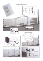
1 Supply package = complete set<br />
Items 2 - 9 are pre-assembled<br />
1. Operator head including 40 W light bulb, base E<br />
27<br />
2. Chain sprocket<br />
3. Track, operator side<br />
4. Carriage<br />
5. Toothed belt or chain<br />
6. Deflection roller<br />
7. Connector<br />
8. Track, door side<br />
9. Tensioner<br />
10. Wall bracket<br />
11. Door connector attachment<br />
12. Linking bar<br />
13. Central support<br />
14. Bag of screws<br />
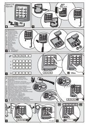
15. Hand transmitter including alkaline battery<br />
23 A, 12 V<br />
16. Support straps<br />
17. Telescopic fitting for sectional doors<br />
(accessory)<br />
2<br />
Overview<br />
3 Track<br />
Remove the packaging and fold out the track to its<br />
full lenght.<br />
Push connector (7) centrally over the joint.<br />
4<br />
7 Suspending the boom from the ceiling<br />
Attach central support (13) to track (8) in front of<br />
the connector (7).<br />
8 Support straps<br />
Positioning the prefitted operator at an angle to the<br />
door, screw to wall bracket (10). Lift up operator,<br />
making sure that it cannot fall down, and align in<br />
such a way that the track runs horizontal and<br />
parallel between the door tracks.<br />
9 Establish the length of the support straps for<br />
the operator head and the central support. If<br />
necessary, shorten using a saw, and then screw in<br />
place.<br />
Note: Before starting any drilling, cover over track<br />
and operator head to protect them from drilling<br />
dust.<br />
Mark fixing points on the ceiling, drill 10 mm holes<br />
for plugs and screw on support straps.<br />
10 If the toothed belt or chain appear to be too<br />
slack, slight retensioning may be required. It may<br />
be necessary to take up the slack by adjusting the<br />
support straps.<br />
11 Connecting the door connector attachment<br />
to the carriage<br />
Place linking bar (12) between carriage (4) and the<br />
door connector attachment (11) and connect at both<br />
ends with the bolts. Provide bolts with security clips.<br />
Attach security clips to bolts.<br />
4 Fastening the track to operator head<br />
Slot track (as illustrated) with chain sprocket (2) onto<br />
the operator shaft (1a) and screw down with the 4<br />
self-tapping screws.<br />
5<br />
Fitting the connector attachment<br />
5a The enclosed door connector attachment is<br />
suitable for all <strong>Novoferm</strong> up-and-over doors and<br />
<strong>Novoferm</strong> Iso20 sectional doors.<br />
Position door connector attachment (11) centrally on<br />
the top edge of the door leaf.<br />
Mark fixing holes and drill using 4 mm metal drill<br />
(max. Drilling depth 10 mm) or use the existing drill<br />
holes. Screw on attachment using enclosed selftapping<br />
screws 6.3 x 16 (4 - 6 screws up-and--over<br />
door, 6 screws - iso20).<br />
5b For other sectional doors, use telescopic fitting<br />
(17) (accessory).<br />
6 Attaching the wall bracket<br />
In order to ensure that the door can run freely<br />
underneath the track, distance “x” must be greater<br />
than 20 mm. Choose distance “x” so that the angle of<br />
the linking bar does not exceed 45° (see figure 11).<br />
Mark the door’s highest point of travel “a” plus<br />
distance “x” on the lintel.<br />
Hold wall fastening (10) at the total height (”a” + “x”)<br />
vertically over the door connector attachment drill,<br />
drill holes for wall plugs and screw the wall bracket<br />
onto the wall.<br />
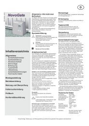
12 Disengaging the carriage<br />
In order to carry out further work, it may be necessary<br />
to disconnect the operator from the door by pulling<br />
the pull cord on carriage (4) and move the door<br />
manually.<br />
Note: If the door is to be operated manually for a<br />
longer period of time, then the locking pin must be<br />
removed from parking position (a) on the left and with<br />
theopull cord in locking position (b).<br />
In order to relock, return the locking pin into the<br />
parking position (a) on the left and restore the<br />
connection between the operator and the door. On<br />
the next movement, the carriage automatically reengages.<br />
13 Aligning the aerial / Connecting plan<br />
Note:<br />
It is essential to pull out the mains plug<br />
before opening the cover!<br />
13 Do not connect any live leads, only<br />
connect potential-free buttons and<br />
potential-free relay outputs.<br />
Finally, re-place the cover and screw<br />
down.<br />
Before using the operator for the first<br />
time, it must be tested to make sure that it<br />
is working properly and safely (see<br />
section on Maintenance/Checks).<br />
E. Connecting the aerial<br />
On the housing exit, angle the aerial down to the<br />
right by approx. 90 ° (as illustrated below).<br />
If using an external aerial, the screen is to be<br />
connected to the adjacent shield terminal (F,<br />
right).<br />
F. Connection for external impulse generator<br />
(Accessory, e. G. Key switch or digital coder)<br />
G.Input STOP A<br />
Connection for safety devices (accessory, e. G.<br />
wicket door contact). A break at this input end<br />
causes the operator to stop or prevents it from<br />
starting up.<br />
Connection for wicket door contact 13a<br />
(accessory)<br />
H.Input STOP B<br />
Connection for safety devices (accessory, e. G.<br />
one-way photocell). A break at this input end<br />
causes the operator to automatically change<br />
direction during the closing cycle.<br />
Connection for 2-wire photocell EXTRA 626 13d<br />
(accessory).<br />
Connection for optical closing edge safety device<br />
OSE 13e (accessory).<br />
I Voltage supply 24 V DC , max. 100 mA<br />
Connection for 24V signal/traffic light 13f<br />
(accessory).<br />
Connection for external receiver 13g.<br />
I. Voltage supply 24 V ~<br />
(e. g. for one-way photocell), connection can take<br />
a maximum load of 100 mA.<br />
J. Plug-in base for radio receiver<br />
K. Connection for external lighting (with earth) or<br />
signal light (protection class II, max. 500W).<br />
Impulse generators and external safety devices<br />
In case of increased need for personal safety, in<br />
addition to the operator’s internatl force limit, we<br />
recommend installing a one-way photocell (see<br />
connecting plan figure 13 ((I) (H)). Further<br />
information on our range of accessories can be<br />
found in our sales literature. Consult your specialist<br />
dealer.<br />
Dismantling the operator<br />
1. Pull out the mains plug and disconnect all existing<br />
terminals.<br />
2. Disconnect door and operator. Fix door.<br />
3. Proceed according to points 3 to 13 of the<br />
installaton Instructions but in reverse sequence.<br />
Retain these installation, operating and maintenance instructions for the full duration of the operator’s service life!