Automazione con sistema a traino per porte basculanti e ... - Came UK
Automazione con sistema a traino per porte basculanti e ... - Came UK
Automazione con sistema a traino per porte basculanti e ... - Came UK

You also want an ePaper? Increase the reach of your titles
YUMPU automatically turns print PDFs into web optimized ePapers that Google loves.
CANCELLI AUTOMATICI<br />
VER<br />
Documentazione<br />
Tecnica<br />
35<br />
rev. 3.3<br />
11/2000<br />
© CAME<br />
CANCELLI<br />
AUTOMATICI<br />
119E35<br />
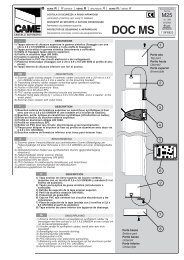
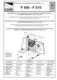
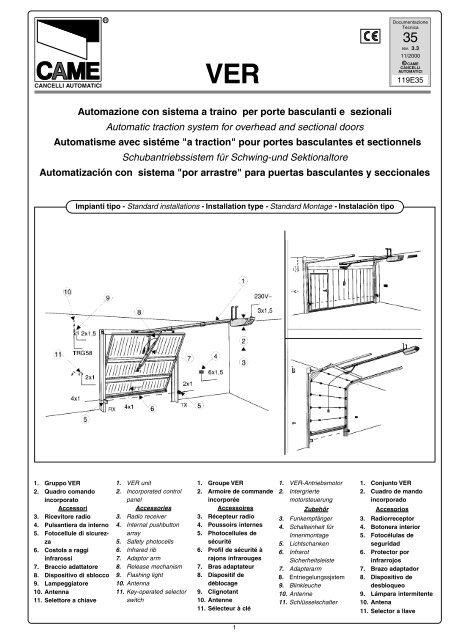
<strong>Automazione</strong> <strong>con</strong> <strong>sistema</strong> a <strong>traino</strong> <strong>per</strong> <strong>porte</strong> <strong>basculanti</strong> e sezionali<br />
Automatic traction system for overhead and sectional doors<br />
Automatisme avec sistéme "a traction" pour <strong>porte</strong>s basculantes et sectionnels<br />
Schubantriebssistem für Schwing-und Sektionaltore<br />
Automatización <strong>con</strong> <strong>sistema</strong> "por arrastre" para puertas basculantes y seccionales<br />
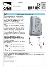
Impianti tipo - Standard installations - Installation type - Standard Montage - Instalaciòn tipo<br />
1. Gruppo VER<br />
2. Quadro comando<br />
incorporato<br />
Accessori<br />
3. Ricevitore radio<br />
4. Pulsantiera da interno<br />
5. Fotocellule di sicurezza<br />
6. Costola a raggi<br />
infrarossi<br />
7. Braccio adattatore<br />
8. Dispositivo di sblocco<br />
9. Lampeggiatore<br />
10. Antenna<br />
11. Selettore a chiave<br />
1. VER unit<br />
2. Incorporated <strong>con</strong>trol<br />
panel<br />
Accessories<br />
3. Radio receiver<br />
4. Internal pushbutton<br />
array<br />
5. Safety photocells<br />
6. Infrared rib<br />
7. Adaptor arm<br />
8. Release mechanism<br />
9. Flashing light<br />
10. Antenna<br />
11. Key-o<strong>per</strong>ated selector<br />
switch<br />
1. Groupe VER<br />
2. Armoire de commande<br />
incorporée<br />
Accessoires<br />
3. Récepteur radio<br />
4. Poussoirs internes<br />
5. Photocellules de<br />
sécurité<br />
6. Profil de sécurité à<br />
rajons infrarouges<br />
7. Bras adaptateur<br />
8. Dispositif de<br />
déblocage<br />
9. Clignotant<br />
10. Antenne<br />
11. Sélecteur à clé<br />
1. VER-Antriebsmotor<br />
2. Intergrierte<br />
motorsteuerung<br />
Zubehör<br />
3. Funkempfänger<br />
4. Schalteinheit für<br />
Innenmontage<br />
5. Lichtschanken<br />
6. Infrarot<br />
Sicherheitsleiste<br />
7. Adapterarm<br />
8. Entriegelungssjstem<br />
9. Blinkleuche<br />
10. Antenne<br />
11. Schlüsselschalter<br />
1. Conjunto VER<br />
2. Cuadro de mando<br />
incorporado<br />
Accesorios<br />
3. Radiorreceptor<br />
4. Botonera interior<br />
5. Fotocélulas de<br />
seguridad<br />
6. Protector por<br />
infrarrojos<br />
7. Brazo adaptador<br />
8. Dispositivo de<br />
desbloqueo<br />
9. Lámpara intermitente<br />
10. Antena<br />
11. Selector a llave<br />
1
CARATTERISTICHE GENERALI - GENERAL SPECIFICATIONS - CARACTÉRISTIQUES GÉNÉRALÉS - ALLGEMEINES DATEN - CARACTERÍSTICAS<br />
GENERALES<br />
Progettato e costruito<br />
interamente dalla<br />
CAME S.p.A. e rispondente<br />
alle vigenti norme<br />
di sicurezza (UNI<br />
8612).<br />
Garantito 12 mesi salvo<br />
manomissioni.<br />
Designed and built<br />
entirety by CAME S.p.A.<br />
in full compliance with<br />
current safety standards<br />
(UNI 8612).<br />
Guaranteed for 12<br />
months unless tam<strong>per</strong>ed<br />
with.<br />
Il a été entièrement<br />
<strong>con</strong>çu et <strong>con</strong>struit par<br />
CAME S.p.A., <strong>con</strong>formément<br />
aux normes de<br />
sécurité en vigueur<br />
(NFP 25.362).<br />
Il est garanti 12 mois sa<br />
uf en cas d’altérations.<br />
Vollständig von der<br />
CAME S.p.A. gemäß<br />
geltender Sicherheilsnormen<br />
(UNI 8612)<br />
Diseñado y fabricado<br />
enteramente por CAME<br />
S.p.A., cumpliendo <strong>con</strong><br />
las normas de seguridad<br />
entwickelt und hergestellt.<br />
(UNI 8612)<br />
Ein Jahr Garantie<br />
unter Varbehalt des<br />
Mißbrauchs.<br />
vigentes.<br />
Garantizado 12 meses<br />
salvo manipulaciones.<br />
LIMITI D'IMPIEGO:<br />
Motoriduttori <strong>con</strong> quadro<br />
comando incorporato,<br />
adatti a motorizzare<br />
portoni sezionali<br />
(fig. A, pag 4), <strong>porte</strong><br />
<strong>basculanti</strong> a molle<br />
(fig. B, pag 4) fino a 2,70<br />
m. di altezza, e <strong>porte</strong><br />
<strong>basculanti</strong> a <strong>con</strong>trappesi<br />
(fig. C, pag 4) fino<br />
a 2,50 m. di altezza; vedere<br />
la voce “ACCESSORI<br />
DI<br />
COMPLETAMENTO”<br />
(pag 4) <strong>per</strong> eventuali<br />
adattamenti.<br />
OPERATING LIMITS:<br />
Gearmotor with built-in<br />
<strong>con</strong>trol panel, suitable for<br />
sectional doors (fig. A,<br />
page 4), spring-batanced<br />
overhead doors (fig. B,<br />
page 4) up to 2, 70 m.<br />
door height and overhead<br />
doors with counterweight<br />
balancing (fig. C,<br />
page 4) up to 2,50 m.<br />
door height.<br />
See<br />
“ACCESSOIRES<br />
SUPPLIED” (page 4) if<br />
adaptation is necessary.<br />
LIMITES D'EMPLOI:<br />
Motoréducteurs avec<br />
armoire de commande<br />
incorporée sont indiqués<br />
pour déplacer des<br />
<strong>porte</strong>s sectionnelles<br />
(fig. A, page 4), <strong>porte</strong>s<br />
basculantes à ressorts<br />
(fig. B, page 4) jusqu’à<br />
2,70 m. de hauteur de la<br />
<strong>porte</strong> et des <strong>porte</strong>s<br />
basculantes à rail<br />
vertical (fig. C, page 4)<br />
jusqu’à 2,50 m. de<br />
hauteur de la <strong>porte</strong>.<br />
voirie paragraphe<br />
“ACCESSOIRES COMPLEMEN-<br />
TAIRES” (page 4) pour<br />
d’éventuelles adaptations.<br />
ANWENDUNGSGEBIET:<br />
Getriebe Motoren mit<br />
LIMITES DE USO:<br />
Motorreductores <strong>con</strong><br />
integriertem Sieuergerät, cuadro de mando<br />
zum Antrieb von incorporada, adecuados<br />
Sektionaltoren (Abb. A,<br />
Seite 4) Federschwingtoren<br />
(Abb. B, Seite 4) bis<br />
auf 2,70 m. Torhöhe und<br />
para motorizar<br />
puertas seccionales<br />
(fig A, pág 4) basculantes<br />
a muelle (fig A,<br />
Schwingtoren mit pág 4) hasta 2,70 m. de<br />
Gegengewicht (Abb. C, la altura y para puerta<br />
Seite 4) bis auf 2,50 m. basculante por<br />
Torhöhe; siehe Abschnitt<br />
“ZUBEHOR” (Seite 4) fur<br />
eventuelle Anpassungen.<br />
<strong>con</strong>trapesos (fig A,<br />
pág 4) hasta 2,50 m. de<br />
la altura; véase el<br />
párrafo “ACCESORIOS DE<br />
COMPLETACION” (pág 4)<br />
para las adaptaciones<br />
eventuales.<br />
ACCESSORI DI CO-<br />
MANDO E SICUREZZA:<br />
è <strong>con</strong>sigliabile installare<br />
le apparecchiature di<br />
comando e di sicurezza<br />
CAME <strong>con</strong> relativi<br />
accessori rendendo<br />
l’impianto di facile esecuzione<br />
e rispondente<br />
alle vigenti norme di sicurezza.<br />
CONTROL AND SAFETY<br />
ACCESSORIES:<br />
we recommend the<br />
installation of CAME<br />
<strong>con</strong>trol and safety<br />
equipment and the relative<br />
accessories; this<br />
facilitates installation and<br />
ensures compliance with<br />
current safety standards.<br />
ACCESSOIRES<br />
DE<br />
COMMANDE ET DE<br />
SECURITE:<br />
il est <strong>con</strong>seillé d’installer<br />
les appareils de<br />
commande et de sécurité<br />
CAME avec les<br />
accessoires correspondants,<br />
ce qui rend<br />
l’installation plus facile<br />
et <strong>con</strong>forme aux<br />
normes de sécurité en<br />
vigueur.<br />
STEUERGERÄTE UND<br />
SICHERHEITS VOR-<br />
RICHTUNGEN:<br />
Es empfiehlt sich CAME<br />
Steuergeräte und<br />
Sicherheitsvorrichtungen<br />
mit dem betreffenden<br />
Zubehör zu montieren;<br />
dadurch wird eine einwandfreie<br />
Mantage der<br />
Anlage und Einhaltung<br />
dergeltenden Sicherheitsnormen<br />
gewährleistet.<br />
ACCESORIOS DE<br />
MANDO Y SEGURIDAD:<br />
es a<strong>con</strong>sejable instalar<br />
los equipos de mando<br />
y seguridad de CAME<br />
junio can sus accesorios,<br />
a fin de que la<br />
instalación sea de fácil<br />
ejecución y cumpla<br />
<strong>con</strong> las vigentes<br />
normas de seguridad.<br />
CARATTERISTICHE TECNICHE - TECNICHAL CARACTERISTICS - CARACTÉRISTIQUES TECHNIQUES - TECNISCHE DATEN<br />
CARACTERÍSTICAS TÉCNICAS<br />
MOTORIDUTTORE<br />
GEAR MOTOR<br />
MOTORÉDUCTEUR<br />
GETRIEBEMOTOR<br />
MOTORREDUCTOR<br />
PESO<br />
WEIGHT<br />
POIDS<br />
GEWICHT<br />
PESO<br />
ALIMENTAZIONE<br />
POWER SUPPLY<br />
ALIMENTATION<br />
STROMVERSORGUNG<br />
ALIMENTACIÓN<br />
ASSORBIMENTO<br />
CURRENT DRAW<br />
ABSORPTION<br />
STROMAUFNAHME<br />
ABSORBENCIA<br />
GRADO DI<br />
PROTEZIONE<br />
PROTECTION<br />
RATING<br />
DEGRÉ DE<br />
PROTECTION<br />
SCHUTZGRAD<br />
GRADO DE<br />
PROTECCION<br />
POTENZA MOTORE<br />
MOTOR POWER<br />
PUISSANCE MOTEUR<br />
MOTORLEISTUNG<br />
POTENCIA MOTOR<br />
INTERMITTTENZA<br />
LAVORO<br />
DUTY<br />
CYCLE<br />
INTERMITTENCE<br />
TRAVAIL<br />
EINSCHALT_<br />
DAUER<br />
INTERMITENCIA<br />
TRABAJO<br />
FORZA<br />
DI TRAZIONE<br />
TRACTION<br />
ORCE<br />
FORCE<br />
DE TRACTION<br />
ZUGKRAFT<br />
FUERZA<br />
DE ARRASTRE<br />
VELOCITA'<br />
MEDIA<br />
AVERAGE<br />
SPEED<br />
VITESSE<br />
MOYENNE<br />
DURCHSCHNITTS_<br />
GESCHWINDIGKEIT<br />
VELOCIDAD<br />
MEDIA<br />
V 200 Kg. 19 230V a.c. 6 A max. IP 40 150 W 50 % 600 N 5 m/min.<br />
2
DESCRIZIONE TECNICA- TECHNICAL DESCRIPTION - DESCRIPTION TECHNIQUE - TECHNISCHE BESCHREIBUNG - DÉSCRIPCION TÉCNICA<br />
- Motore alimentato a<br />
24V d.c.<br />
- cassa del riduttore in<br />
alluminio pressofuso.<br />
All’interno o<strong>per</strong>a un <strong>sistema</strong><br />
di riduzione<br />
irreversibile a vite senza<br />
fine e corona<br />
elicoidale. La<br />
lubrificazione è a grasso<br />
fluido <strong>per</strong>manente.<br />
- quadro elettrico e lampada<br />
di illuminazione<br />
ambiente incorporati.<br />
- gruppo montato su<br />
una base guida in lamiera<br />
zincata.<br />
- co<strong>per</strong>chio in materiale<br />
plastico <strong>con</strong> rifrangente<br />
<strong>per</strong> illuminazione<br />
ambiente.<br />
- gruppo finecorsa <strong>con</strong><br />
2 microinterruttori.<br />
- n. 3 guide <strong>per</strong> lo scorrimento<br />
della catena, n.<br />
5 staffe e n. 2 staffe di<br />
giunzione in lamiera<br />
zincata.<br />
- 24V d.c. motor<br />
- reduction gear unit<br />
housed in a die-cast<br />
aluminium casing. The<br />
unit features an<br />
irreversible reduction<br />
gear with worm screw<br />
and helicoidal<br />
ring. Permanently<br />
lubricated with liquid<br />
grease.<br />
- built-in <strong>con</strong>trol panel<br />
and light for illumination<br />
of the area around the<br />
door.<br />
- the motor is mounted on<br />
a base-guide in<br />
galvanised sheet metal.<br />
- plastic cover with<br />
refractive etement for<br />
illumination of the area<br />
nearby.<br />
- limit switch with 2<br />
microswitches.<br />
- n. 3 guides for sliding<br />
chain, n. 5 brackets and<br />
n. 2 junction bracket<br />
gatvanised sheet metal.<br />
- Moteur alimenté à 24 V<br />
d.c.<br />
- coffre du réducteur<br />
réalisé en aluminium<br />
moulé sous pression. A<br />
l’intérieur agi’ un<br />
système de réduction<br />
irréversible à vis sans<br />
fin et couronne<br />
h é licoidale.<br />
Lubrification <strong>per</strong>manente<br />
par graisse fluide.<br />
- armoire électrique et<br />
lampe d’éclairage du<br />
lieu incorporées.<br />
- groupe monté sur une<br />
base-guide en tôle<br />
galvanisée.<br />
- couvercle réalisé en<br />
matériau plastique<br />
avec élément<br />
réfringent pour<br />
l’éclairage du lieu.<br />
- groupe lins de<br />
course avec 2<br />
microinter-rupteurs.<br />
- n. 3 guides pour le<br />
coulissement de la<br />
chaîne, n. 5 étriers et n.<br />
2 étrieres de jonction.<br />
- Gleichstrommolor 24V<br />
d.c.<br />
- Untersetzungsgetriebe<br />
in Aluminiumdruckguß<br />
gehä use.<br />
Irreversibles Schnecken/<br />
Schrägzahnraduntersetzungsgetriebe.<br />
Dauerschmierung mirreis<br />
flüssigem Schmiermittel.<br />
- Steuergerät und<br />
Garagenbeieuchjung<br />
injegrien.<br />
- Anirieb auf<br />
Schienenprofil aus<br />
verzinktem Blech<br />
montiert.<br />
- Plastikhaube mit<br />
Lichtbrecher für<br />
Garagenbeleuchtung .<br />
- Endanschlag-Satz mit 2<br />
Mikroschalter.<br />
- 3 Laufschienen zur<br />
Kettenführung, 5<br />
Befestigungsbügel und 2<br />
Verbindungsstück.<br />
- Motar alimentado <strong>con</strong><br />
24V d.c.<br />
- caja del reductor de<br />
aluminio fundido. En<br />
su interior obra un <strong>sistema</strong><br />
de reducción<br />
irreversible por tornillo<br />
sin fin y corona<br />
hellcoidal. La<br />
lubricación es <strong>per</strong>manente,<br />
por grasa fluida.<br />
- cuadro de mando y<br />
lámpara de alumbrado<br />
a m b i e n t e<br />
incorporados.<br />
- <strong>con</strong>junto montado en<br />
una base guía de<br />
chapa galvanizada.<br />
- tapa de plástico<br />
dolada de refringente<br />
para el alumbrado ambiente.<br />
- grupo final de carrera<br />
<strong>con</strong> 2 microinterruptores.<br />
- n. 3 guias para el<br />
deslizamiento de la<br />
cadena, n. 5 so<strong>porte</strong>s y<br />
n. 2 so<strong>porte</strong>s de unión.<br />
MISURE D'INGOMBRO - EXTERNAL DIMENSIONS - MEASURES D'ENCOMBRENT - ABMESSUNGEN - DIMENSIONES<br />
2<br />
40<br />
Uscita cavi<br />
Cable exit<br />
Sortie cables<br />
Netzkabeleingang<br />
Salida de los cables<br />
* Per altezze su<strong>per</strong>iori a tale valore, prevedere dei tiranti o staffe supplementari<br />
For heights exceding 540 mm., it is necessary to use additional brackets or struts<br />
Pour des hauteurs su<strong>per</strong>ieures a cette valeur, prevoir des tirants ou des etriers supplementaires<br />
Bei Höhen, die obiges Maß überschreiten zusätzliche Schubstangen oder Bügel montieren<br />
Para las alturas mayores que esta medida, se deben utilizar unos tirantes o so<strong>porte</strong>s adicionales<br />
3
ACCESSORI DI COMPLETAMENTO - ACCESSOIRES SUPPLIED - ACCESSOIRES COMPLEMENTAIRES - ZUBEHOR - ACCESORIOS DE<br />
COMPLETACION<br />
- V122: leva <strong>per</strong> <strong>porte</strong><br />
sezionali A. Da applicare<br />
quando la distanza<br />
fra il palo-molla e la battuta<br />
su<strong>per</strong>iore del portone<br />
è compresa fra 30<br />
e 60 cm. (pag 5).<br />
- V201: <strong>sistema</strong> adattatore<br />
<strong>per</strong> <strong>porte</strong> <strong>basculanti</strong><br />
C a <strong>con</strong>trappesi<br />
(pag 5).<br />
- V122: bracket for<br />
sectional doors A.<br />
Recommended when the<br />
distance between the<br />
spring-bar and the up<strong>per</strong><br />
edge of the door is<br />
between 30 and 60 cm.<br />
(page 5).<br />
- V201: adaptor arm for<br />
overhead doors C with<br />
counterweight balancing<br />
(page 5).<br />
- V122: levier pour<br />
<strong>porte</strong>s sectionnelles A.<br />
Celui-ci doit être<br />
appliqué lorsque la<br />
distance entre la barre<br />
du ressort et le point de<br />
fermeture supérieur de<br />
la <strong>porte</strong> est comprise<br />
entre 30 et 60 cm (page<br />
5).<br />
- V201: système adaptateur<br />
pour <strong>porte</strong>s<br />
basculantes C à <strong>con</strong>trepoids<br />
(page 5).<br />
- V122: Hebel für<br />
Sektionaltor A. Der Hebel<br />
wird bei Sektionaltoren,<br />
wenn der Absland<br />
zwischen Federbügel<br />
und oberer Torkante<br />
zwischen 30 und 60 cm<br />
liegt, angewendet. (Seite<br />
5).<br />
- V201: Adaptersystem<br />
für Schwingtore C mit<br />
Gegengewicht (Seite 5).<br />
- V122: palanca para<br />
puertas seccionales A.<br />
Se debe aplicar cuando<br />
la distancia entre la<br />
barra-resorte y el punto<br />
de <strong>con</strong>tacto su<strong>per</strong>ior<br />
de la puerta es 30 a 60<br />
cm (pág 5).<br />
- V201: <strong>sistema</strong> adaptador<br />
para puertas<br />
basculantes C por<br />
<strong>con</strong>trapesos (pág 5).<br />
- V203: <strong>con</strong>fezione<br />
completa di: 1 guida, 1<br />
staffa di giunzione, 1<br />
giunto <strong>per</strong> catena e 2 m.<br />
di catena <strong>per</strong> l’aumento<br />
della corsa di 1 m.<br />
(pag 5).<br />
- V203: extension kit<br />
including 1 guide, 1 junction<br />
bracket, 1 chain<br />
coupling link and a 2 m.<br />
chain extension to<br />
increase the movement<br />
of 1 m. (page 5).<br />
- V203: emballage<br />
comprenant : 1 guide, 1<br />
étrier de jonction, 1<br />
pièce de jonction pour<br />
chaîne et 2 m de chaîne<br />
pour une augmentation<br />
de course de 1 m. (page<br />
5).<br />
- V203: Kompletter<br />
Bausalz: 1 Laufschiene,<br />
1 Verbindungsstück, 1<br />
Kerenkupplung und 2 m<br />
Kette zur Fahrwegverlängerung<br />
um 1 m<br />
(Seite 5).<br />
- V203: embalaje<br />
formado por: 1 guía, 1<br />
so<strong>porte</strong> de unión, 1<br />
unión para cadena y 2<br />
m de cadena para aumentar<br />
1 m la carrera<br />
(pág 5).<br />
ESEMPI DI APPLICAZIONE - EXAMPLES OF APPLICATIONS - EXEMPLES D’APPLICATIONS - INSTALLATIONSBEISPIELE<br />
EJEMPLOS DE APLICACIONES<br />
A<br />
B<br />
C<br />
A - Portone sezionale<br />
Sectional door<br />
Porte sectionnelle<br />
Sektionaltor<br />
Puerta seccional<br />
B - Porta basculante a molle<br />
Spring-balanced overhead door<br />
Porte basculante à ressort<br />
Feder-Schwingtor<br />
Puerta basculante a muelle<br />
C - Porta basculante a <strong>con</strong>trappesi<br />
Overhead door with counterweight balancing<br />
Porte basculante à rail vertical<br />
Schwingtor mit Gegengewichten<br />
Puerta basculante por <strong>con</strong>trapesos<br />
4
ACCESSORI DI COMPLETAMENTO - ACCESSOIRES SUPPLIED - ACCESSOIRES COMPLEMENTAIRES - ZUBEHOR - ACCESORIOS DE COMPLETACION<br />
V122<br />
Leva <strong>per</strong> portoni sezionali<br />
Lever for sectional doors<br />
Levier pour <strong>porte</strong>s à lattes<br />
Hebel für Sektionaltore<br />
Palanca para puertas seccionales<br />
- Questa leva si applica<br />
quando la distanza fra il<br />
palo-molla e la battuta<br />
su<strong>per</strong>iore del portone è<br />
compresa fra 30 e 60<br />
cm.<br />
V201<br />
Braccio adattatore <strong>per</strong> <strong>porte</strong><br />
<strong>basculanti</strong> a <strong>con</strong>trappesi<br />
- This lever should be<br />
fitted when the distance<br />
between the spring-bar<br />
and the up<strong>per</strong> edge of the<br />
door is between 30 and<br />
60 cm.<br />
- On applique ce levier<br />
lorsque la distance<br />
entre la barre-ressort et<br />
le point de fermeture<br />
supérieur de la <strong>porte</strong> est<br />
comprise entre 30 et<br />
60 cm.<br />
- Dieser Hebel wird<br />
montiert, wenn der<br />
Abstand zwischen<br />
Federträger und oberem<br />
Toranschlag zwischen 30<br />
und 60 cm liegt.<br />
- Esta palanca se debe<br />
incorporar cuando la<br />
distancia entre la barraresorte<br />
y el punto de<br />
<strong>con</strong>tacto su<strong>per</strong>ior de la<br />
puerta es 30 a 60 cm.<br />
Adaptor arm for overhead doors with<br />
counterweights<br />
Bras d'adaptation pour <strong>porte</strong>s<br />
basculantes à <strong>con</strong>trepoids<br />
Adapterarm für Schwingtore mit<br />
Gegengewichten<br />
Brazo adaptador para puertas<br />
basculantes a <strong>con</strong>trapesos<br />
V203<br />
Prolunga <strong>per</strong> l'aumento della corsa di 1 m.<br />
Extension guide for 1 m. extension of movement<br />
Rallonge pour une augmentation de course de 1 m<br />
Verlängerungsstück zur Fahrwegverlängerung um 1 m<br />
Pieza de prolongación para aumentar 1 m la carrera<br />
- Da applicare nel caso<br />
l'altezza della porta sia<br />
compresa fra i 2,50 e i<br />
3,50 metri.<br />
- The extension guide<br />
should be used if the<br />
height of the door is<br />
between 2.5 and 3.5 metres.<br />
- A appliquer si la<br />
hauteur de la <strong>porte</strong> est<br />
comprise entre 2.50 et<br />
3.50 mètres.<br />
- Der Bausatz wird bei<br />
Torhöhen zwischen 2.50<br />
und 3.50 m installiert.<br />
- Se debe incorporar<br />
cuando la altura de la<br />
puerta es 2.50 a 3.50<br />
metros.<br />
PER ULTERIORI INDICAZIONI,<br />
CONSULTARE I FOGLI TECNICI<br />
ALLEGATI ALLE CONFEZIONI<br />
DEGLI ACCESSORI<br />
FOR FURTHER DETAILS, REFER<br />
TO THE TECHICAL DATA SHEETS<br />
SUPPLIED WITH THE<br />
ACCESSOIRES<br />
POUR D'AUTRES INDICATIONS,<br />
CONSULTER LES FEUILLETES<br />
TECHNIQUÉS FOURNIS AVEC<br />
LES ACCESSOIRES<br />
WEITERE INSTALLATIONSTIPS<br />
FINDEN SIE IN DEN DER<br />
Z UBEHÖ RVERPACKUNG<br />
BEIGELEGTEN TECHNISCHEN<br />
PARA MÀS INFORMACIONES,<br />
VÉANSE LOS FOLLETOS<br />
TÉCNICOS ADJUNTOS A LOS<br />
EMBALAJES DE LOS<br />
DATENBLÄTTERN<br />
ACCESORIOS<br />
5
ASSEMBLAGGIO DEL GRUPPO - ASSEMBLING THE UNIT - ASSEMBLAGE DU GROUPE - ZUSAMMENBAU DES ANTRIEBS<br />
MONTAJE DEL CONJUNTO<br />
1<br />
Guida<br />
Guide<br />
Guide<br />
Schiene<br />
Guía<br />
Predisporre il gruppo collegando le tre guide mediante le<br />
due staffe di giunzione.<br />
Connect the three guides sections using the two junction<br />
brackets.<br />
Préparer le groupe en assemblant le 3 guides à l'aide<br />
des 2 étriers de jonction.<br />
Staffa di giunzione<br />
Junction bracket<br />
Etrier de jonction<br />
Verbindungsstück<br />
So<strong>porte</strong> de union<br />
Die drei Schienenteile mittels der beiden Verbindungsstücke<br />
zusammensetzen.<br />
Emplazar el grupo empalmando las 3 guías mediante<br />
los 2 so<strong>porte</strong>s de uníon.<br />
ATTENZIONE: Se l’altezza<br />
della porta è su<strong>per</strong>iore<br />
ai limiti di impiego<br />
di pag. 2, applicare<br />
l’accessorio V203,<br />
aggiungendo la guida e<br />
la staffa di giunzione.<br />
Collegare i 2 m di catena<br />
aggiuntiva a quella<br />
già assemblata mediate<br />
il giunto <strong>per</strong> catena.<br />
N.B. If the height of the<br />
door is over the o<strong>per</strong>ating<br />
limits at page 2, use the<br />
V203 extension kit,<br />
adding the supplementy<br />
guide and junction<br />
bracket. Connect the 2<br />
metre chain extension to<br />
the original chain, using<br />
the chain coupling link.<br />
ATTENTION: Si la<br />
hauteur de la <strong>porte</strong> est<br />
su<strong>per</strong>iore aux limits<br />
d’emploi à la pag. 2, il<br />
faut appliquer l’accessoire<br />
V203, en ajoutant le<br />
guide et l’étrier de<br />
jonction. Unir les 2 m de<br />
chaîne supplémentaire à<br />
celle déjà assemblée en<br />
utilisant la pièce de<br />
jonction pour chaîne.<br />
WICHTIG! Wäre die<br />
Torhöhe über dem<br />
Anwendungsgebiet<br />
(Seite 2), muß der<br />
Zubehörsatz V203 mit<br />
zusätzlicher Schiene und<br />
Verbin-dungsstü ck<br />
montiert werden. Die 2 m<br />
lange Kette mittels dei<br />
Kettenkupplung mit der<br />
bereits montierten Kette<br />
verbinden.<br />
CUIDADO: Si la altura<br />
de la puerta es major<br />
de los limites de uso de<br />
la pág. 2, aplicar el<br />
accesorio V203,<br />
incorporandoo la guía<br />
y el so<strong>porte</strong> de uníon.<br />
Empalmar los 2 m de<br />
cadena adicional a la<br />
que ya se ha montado,<br />
por medio de la unión<br />
para cadena.<br />
2<br />
Staffa “C”<br />
Bracket “C”<br />
Etrier “C”<br />
Befestigungsbügel “C”<br />
So<strong>porte</strong> “C”<br />
Leva<br />
Arm<br />
Levier<br />
Hebel<br />
Palanca<br />
Catena<br />
Chain<br />
Chaîne<br />
Kette<br />
Cadena<br />
Attacco tendicatena<br />
Chain tensioner coupling<br />
Pièce de tension de la<br />
chaine<br />
Kettenspanneranschlüß<br />
Empalme tensor de cadena<br />
Giunto<br />
Chain coupling link<br />
Pièce de jonction<br />
Kupplung<br />
Union<br />
Vite di regolazione<br />
Regulation screw<br />
Vis de réglage<br />
Regelschraube<br />
Tornillo de ajuste<br />
Guida<br />
Guide<br />
Guide<br />
Schiene<br />
Guía<br />
Pattino<br />
Sliding block<br />
Patin<br />
Gleitbacke<br />
Patin<br />
- Inserire la catena all’interno<br />
delle guide posizionando<br />
il giunto e il<br />
pattino a circa metà<br />
della lunghezza totale<br />
delle guide <strong>con</strong> l’attacco<br />
tendicatena nella<br />
posizione illustrata.<br />
- Insert the chain into the<br />
guides, positioning the<br />
chain coupling and the<br />
sliding block at approximately<br />
the midway<br />
point of the guides. The<br />
chain tensioner coupling<br />
should be positioned as<br />
shown in the figure.<br />
- Introduire la chaîne à<br />
l’intérieur des guides<br />
en positionnent la pièce<br />
de jonction et le<br />
patin à une distance<br />
correspondant à environ<br />
la moitié de la longueur<br />
totale des guides<br />
et en plaçant la pièce<br />
de tension de la chaîne<br />
de la manière indiquée<br />
dans la figure.<br />
- Die Kette in die<br />
Laufschiene einsetzen<br />
und Kettenkupplung und<br />
Gleit backe etwa in der<br />
Mitte der Gesamt Länge<br />
der Schienen plazieren.<br />
Der Kettenspanneranschluß<br />
sollte gemäß der<br />
Abbildung liegen.<br />
- Introducir la cadena<br />
en las guias colocando<br />
la unión y el patín en la<br />
mitad de la longitud<br />
total de las guías, <strong>con</strong><br />
el empalme tensor de<br />
cadena en la posición<br />
indicada.<br />
6
3<br />
Innesti<br />
Guide anchor slots<br />
Eléments de fixation<br />
Klemmen<br />
Uniones<br />
Collegare la catena al<br />
pignone facendola<br />
sporgere leggermente<br />
dalle guide e ancorare<br />
le guide alla base del<br />
motoriduttore sugli appositi<br />
innesti.<br />
Fit the chain to the pinion<br />
and insert the guides into<br />
the anchor slots on the<br />
gear motor.<br />
Unir la chaîne au<br />
pignon et fixer les<br />
guides à la base du<br />
motoréducteur sur les<br />
éléments de fixation<br />
appropriés.<br />
Die Kette so auf den<br />
Antriebsritzel spannen,<br />
und die Schienen am<br />
Getriebemotorgehäuse<br />
in den ent sprechenden<br />
Klemmen einrasten.<br />
Enzalar la cadena al<br />
piñon y fijar las guías<br />
en la base del motorreductor,<br />
en las uniones<br />
especificas.<br />
4<br />
Staffa “A”<br />
Bracket “A”<br />
Etrier “A”<br />
Befestigungsbügel “A”<br />
So<strong>porte</strong> “A”<br />
Dado<br />
Nut<br />
Ecrou<br />
Mutter<br />
Tuerca<br />
Rondella<br />
Washer<br />
Rondelle<br />
Unterlegschleibe<br />
Arandela<br />
Guida<br />
Guide<br />
Guide<br />
Schiene<br />
Guía<br />
Molla<br />
Spring<br />
Ressort<br />
Feder<br />
Resorte<br />
Vite di regolazione<br />
Regulation screw<br />
Vis de réglage<br />
Regelschraube<br />
Tornillo de ajuste<br />
- Inserire la staffa “A”<br />
nell’attacco tendicatena<br />
e regolare la tensione<br />
della catena<br />
agendo sul dado.<br />
N.B.: la catena deve essere<br />
leggermente messa<br />
in tensione.<br />
- Fin bracket “A” to the<br />
chain tensioner <strong>con</strong>nector<br />
and turn the nut to<br />
adjust the tension of the<br />
chain.<br />
N.B.: The chain must be<br />
slightly taut.<br />
- Introduire l’étrier “A”<br />
dans la pièce de tension<br />
de la chaîne et<br />
régler la tension de la<br />
chaine en agissant sur<br />
l’écrou.<br />
N.B.: la chaîne doit être<br />
légèrement tendue.<br />
- Den Belestigungsbügel<br />
“A” in den Kettenspannanschluß<br />
stecken und<br />
die Kettenspannung<br />
mittels der Mutter<br />
einstellen.<br />
Anmerkung: Die Kette<br />
muß leicht gespannt<br />
sein.<br />
- Introducir el so<strong>porte</strong><br />
“A” en el empalme<br />
tensor de cadena y<br />
regular la tensión de la<br />
cadena actuando sobre<br />
la tuerca.<br />
N.B.: la cadena debe<br />
someterse ligeramente<br />
a tensión.<br />
7
Telaio della porta<br />
Door frame<br />
Châssis de la <strong>porte</strong><br />
Torrahmen<br />
Bastídor de la puerta<br />
Staffa “A”<br />
Bracket “A”<br />
Etrier “A”<br />
Befestigungsbügel “A”<br />
So<strong>porte</strong> “A”<br />
5<br />
Fissare centralmente<br />
(<strong>con</strong> viti o rivetti) la<br />
staffa “A” al telaio della<br />
porta (montaggio<br />
<strong>con</strong>sigliato) o al muro,<br />
Bolt or rivet bracket “A “<br />
in the Gen tre of the door<br />
frame (recommended<br />
position) or to the wall<br />
itself, about 10-20 mm<br />
Fixer (à l’aide de vis ou<br />
de rivets) l’étrier “A”<br />
sur le châssis de la <strong>porte</strong><br />
(montage <strong>con</strong>seillé)<br />
ou sur le mur, de façon<br />
a circa 10-20 mm. sopra above the highest à ce que l’étrier soit<br />
il punto massimo di<br />
scorrimento dell’anta.<br />
position reached by the<br />
door during movement.<br />
positionné au centre,<br />
10-20 mm au-dessus<br />
du point supérieur de<br />
coulissement du<br />
vantail.<br />
Den Belestigungsbügel<br />
“A” mitting am Torprolil<br />
(empfohlene Montage)<br />
oder an der Decke mit<br />
Schrauben bzw. Nieten<br />
befestigen, ca. 10-20 mm<br />
über<br />
Torhöchstpunkl<br />
Tores.<br />
dem<br />
des<br />
Fijar en el centro (por<br />
medio de tornillos o<br />
remaches) el soporle<br />
“A” en el bastidor de la<br />
puerta (montaje<br />
a<strong>con</strong>sejado) o en la<br />
pared, a unos 10-20<br />
mm encima del punto<br />
su<strong>per</strong>ior de deslizamiento<br />
de la hoja.<br />
6<br />
Angolari<br />
Angle-brackets<br />
Cornières<br />
Winkeleisem<br />
Escuadras<br />
Pressacavo<br />
Cable fairlead<br />
Serre-câble<br />
Kabelhülse<br />
Abrazadera de cables<br />
Staffe “B”<br />
Brackets “B”<br />
Etriers “B”<br />
Befestigungsbügel “B”<br />
So<strong>porte</strong>s “B”<br />
Co<strong>per</strong>chio<br />
Cover<br />
Couvercle<br />
Haube<br />
Tapa<br />
Foro <strong>per</strong> pressacavo<br />
Hole for cable fairlead<br />
Trou pour serre-câble<br />
Kabelhülsenbohrung<br />
Agujero para la<br />
abrazadera<br />
de cables<br />
Togliere il co<strong>per</strong>chio e<br />
applicare:<br />
- il pressacavo in dotazione<br />
- le staffe “B” al gruppo<br />
e successivamente al<br />
soffitto mediante gli<br />
appositi angolari utilizzando<br />
viti e tasselli.<br />
Remove the cover and<br />
lift:<br />
- the cable fairlead<br />
supplied with the unit<br />
- the “B” brackets to the<br />
unit and then to the<br />
ceiling using the angle<br />
brackets to be fixed with<br />
some screws or bolts.<br />
Enlever le couvercle et<br />
appliquer:<br />
- le serre-câble fourni<br />
avec le matériel<br />
- les étriers “B” sur le<br />
groupe et puis au<br />
plafond en utilisant<br />
les cornières avec de<br />
vis ou de chevilles.<br />
8<br />
Deckel abnehmen und:<br />
- mitgelieferte Kabelschelle<br />
und<br />
- Bügel anbringen und<br />
dann die Gruppe mit<br />
den entsprechenden<br />
Winkeleisen mittels<br />
Schrauben und Dübeln<br />
an der Decke befestingen.<br />
Quitar la tapa del motorreductor<br />
y aplicar:<br />
- la abrazadera de<br />
cables suministrada<br />
- los so<strong>porte</strong>s “B” en el<br />
<strong>con</strong>junto y sucesivamente<br />
en el tecio por<br />
medio de las éscuadras<br />
utilizando los<br />
tornillos<br />
expansión.<br />
de
7<br />
- Fissare la staffa “C” sul traverso su<strong>per</strong>iore dell’anta <strong>con</strong><br />
i rivetti in dotazione.<br />
- Fasten bracket “C” to the up<strong>per</strong> cross-member of the door<br />
using the rivets supplied with the unit.<br />
- Fixer l’étrier “C” sur la traverse supérieure du vantail en<br />
utilisant les rivets fournis avec le matériel.<br />
- Den Befestigungbügel “C” am oberen Torquerträger mit den<br />
mitgelieferten Nieten befestigen.<br />
- Fijar el so<strong>porte</strong> “C” en el travesaño su<strong>per</strong>ior de la hoja<br />
por medio de los remaches suministrados.<br />
Leva<br />
Arm<br />
Levier<br />
Hebel<br />
Palanca<br />
Traverso<br />
Cross-member<br />
Traverse<br />
Querträger<br />
Traversaño<br />
Rivetto<br />
Rivet<br />
Rivet<br />
Niet<br />
Remache<br />
Staffa “C”<br />
Bracket “C”<br />
Etrier “C”<br />
Befestigungsbügel “C”<br />
So<strong>porte</strong> “C”<br />
ATTENZIONE: vedere<br />
alla voce “ACCESSORI<br />
A RICHIESTA” di pag 4,<br />
<strong>per</strong> la sostituzione della<br />
staffa “C” e della leva<br />
<strong>con</strong> <strong>sistema</strong> V201 (<strong>porte</strong><br />
<strong>basculanti</strong>) o il braccio<br />
V122 (alcuni sezionali).<br />
N.B. If it is necessary to<br />
replace the standard<br />
bracket “C” and the<br />
standard arm with the<br />
V201 kit (for overhead<br />
doors) or V122 kit (for<br />
sectional doors), refer to<br />
paragraph “OPTIONAL<br />
ACCESSORIES “ on<br />
page 4.<br />
ATTENTION: Se re<strong>porte</strong>r<br />
au paragraphe<br />
“ACCESSOIRES SUR<br />
DEMANDE” de la page<br />
4 pour remplacer<br />
l’étrier “C” et le levier<br />
Parle système V201<br />
(<strong>porte</strong>s basculantes)<br />
ou parle bras V122<br />
(certaines <strong>porte</strong>s<br />
sectionnelles).<br />
WICHTIG! Für den<br />
Austausch des Befestigungsbügels<br />
“C” und des<br />
Hebels gegen das<br />
System V201 (Schwingtor)<br />
bzw. V122 (einige<br />
Sektionaltere) siehe<br />
Abschnitt “ZUBEHÖR<br />
AUF ANFRAGE” Seite 4.<br />
CUIDADO: para la<br />
sustitución del so<strong>porte</strong><br />
“C” y de la palanca por<br />
el <strong>sistema</strong> V201<br />
(puertas basculantes)<br />
o el brazo V122<br />
(algunas puertas<br />
seccionales), véase el<br />
párralo “ACCESORIOS<br />
OPCIO-NALES“ en<br />
pág. 4.<br />
8<br />
Predisporre l’arrivo dei<br />
cavi di alimentazione al<br />
gruppo motore e procedere<br />
al collegamento<br />
elettrico (pag. 15/16).<br />
Install the electrical<br />
wiring and <strong>con</strong>nect ad<br />
indicated (pag 15/16).<br />
Préparer l’arrivée des<br />
câbles d’alimentation<br />
sur le groupe moteur et<br />
effectuer le branchement<br />
électrique<br />
(pag 15/16).<br />
Die Motor-Netzanschlußkabel<br />
verlegen<br />
und den elektrischen<br />
Anschluß vornehmen<br />
(Seite 15/16).<br />
Disponer la salida de<br />
los cables de alimentación<br />
hacia el <strong>con</strong>junto<br />
motor y llevar a<br />
cabo las <strong>con</strong>exiones<br />
eléctricas (pág 15/16).<br />
9
ITALIANO<br />
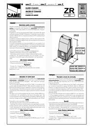
DESCRIZIONE TECNICA SCHEDA BASE ZL54<br />
La scheda comando va alimentata a<br />
(230V a.c.) sui morsetti L1 e L2 ed è<br />
protetta in ingresso <strong>con</strong> fusibile da 3.15A.<br />
I dispositivi di comando sono a bassa<br />
tensione (24V), protetti <strong>con</strong> fusibile da<br />
1A.<br />
La potenza complessiva degli accessori<br />
a 24V non deve su<strong>per</strong>are i 30W (esclusa<br />
lampada di cortesia).<br />
Sicurezza<br />
Le fotocellule possono essere collegate<br />
e predisposte <strong>per</strong>:<br />
a) Ria<strong>per</strong>tura in fase di chiusura;<br />
b) Stop totale: arresto dell'anta <strong>con</strong> <strong>con</strong>seguente<br />
esclusione dell'eventuale ciclo<br />
di chiusura automatica, <strong>per</strong> riprendere il<br />
movimento agire sulla pulsantiera o sul<br />
trasmettitore radio;<br />
- Dispositivo am<strong>per</strong>ometrico: vedi NOTA<br />
- Tempo di lavoro fisso 90 se<strong>con</strong>di.<br />
Accessori collegabili<br />
- Scheda LB54 che <strong>per</strong>mette l'alimentazione<br />
dell'automazione tramite batterie<br />
nel caso di mancanza di energia elettrica.<br />
Al ripristino della tensione di linea esegue<br />
anche la loro ricarica (vedi relativo foglio<br />
istruzioni);<br />
- Lampeggiatore di movimento;<br />
- Ricevitore radio ad innesto.<br />
Altre funzioni selezionabili<br />
- Chiusura automatica. Il temporizzatore<br />
di chiusura automatica si autoalimenta a<br />
finecorsa di a<strong>per</strong>tura. Il tempo regolabile, é<br />
comunque subordinato dall'intervento di<br />
eventuali accessori di sicurezza e si esclude<br />
dopo un intervento di «stop» totale o in<br />
mancanza di energia elettrica;<br />
- Rilevazione d'ostacolo <strong>con</strong> motore a<br />
finecorsa (anta completamente a<strong>per</strong>to o<br />
chiuso), annulla ogni comando in caso di<br />
ostacolo rilevato dai dispositivi di sicurezza<br />
(es: fotocellule);<br />
- Funzione a «uomo presente». Funzionamento<br />
del cancello mantenendo premuto<br />
il pulsante (esclude la funzione del<br />
radiocomando);<br />
- Prelampeggio in a<strong>per</strong>tura e chiusura;<br />
- Tipo di comando:<br />
-apre-chiude-inversione;<br />
-apre-stop-chiude-stop;<br />
-solo a<strong>per</strong>tura.<br />
Regolazioni<br />
- Trimmer TCA = Tempo chiusura automatica:<br />
da 0" a 120";<br />
- Trimmer RALL = Tempo di rallentamento:<br />
0" a 8";<br />
- Trimmer SENS = Sensibilità am<strong>per</strong>ometrica:<br />
min/max.<br />
Attenzione: prima di intevenire all’interno<br />
dell’apparecchiatura, togliere la<br />
tensione di linea e scollegare le batterie<br />
(se inserite).<br />
ENGLISH<br />
This <strong>con</strong>trol board is powered by 230V<br />
a.c. across terminals L1 and L2, and is<br />
protected by a 3.15A fuse on the main<br />
power line.<br />
Control systems are (24) powered by low<br />
voltage and protected with by a 1A fuse.<br />
The total power <strong>con</strong>sumption of 24V<br />
accessories must not exceed 30 W (not<br />
included courtesy light).<br />
Safety<br />
Photocells can be <strong>con</strong>nected to obtain:<br />
a)Re-opening during the closing cycle;<br />
b)Total stop: the movement of the bar is<br />
interrupted, and the automatic closure<br />
cycle is disactivated. Use the keyboard<br />
or the radio transmitter to resume<br />
movement of the door wing;<br />
- Am<strong>per</strong>ometric safety device: see<br />
NOTE;<br />
- Fixed o<strong>per</strong>ating time of 90 sec.<br />
Accessories which can be<br />
<strong>con</strong>nected<br />
TECHNICAL DESCRIPTION ZL54 MOTHERBOARD<br />
to this unit<br />
- LB54 board, used to power the<br />
automation system using battery power<br />
in case of a power failure. When the power<br />
supply is restored, the batteries are<br />
recharged automatically (refer to<br />
instruction sheet);<br />
- Flashing signal light when door wing is<br />
in motion;<br />
- Plug-in radio receiver<br />
Other functions available<br />
- Automatic closing: The automatic<br />
closing timer is automatically activated at<br />
the end of the opening cycle. The preset,<br />
adjustable automatic closing time is<br />
automatically interrupted by the activation<br />
of any safety system, and is deactivated<br />
after a total stop command or in case of<br />
power failure;<br />
- Detection of obstacles: this function with<br />
motor at limit position (door wing<br />
completely opened or closed). This device<br />
cancels every command if an obstacle is<br />
detected by the security devices (ex.<br />
photocells);<br />
- “O<strong>per</strong>ator present” function. Gate<br />
o<strong>per</strong>ates only when the pushbutton is<br />
held down (the radio remote <strong>con</strong>trol<br />
system is deactivated);<br />
- Flashing light activated before opening<br />
and closing cycle begins;<br />
- Selection of command sequence:<br />
-open-close-reverse;<br />
-open-stop-close-stop;<br />
-open only.<br />
Adjustments<br />
- Trimmer TCA = Automatic closing time:<br />
0" to 120";<br />
- Trimmer RALL = Slowdown time: 0" to<br />
8";<br />
- Trimmer SENS = Sensitivity of<br />
am<strong>per</strong>ometricsafety system: min/max.<br />
Important: Shut off the mains power<br />
and dis<strong>con</strong>nect the batteries before<br />
servicing the inside of the unit.<br />
FRANÇAIS<br />
La carte de commande doit être<br />
alimentée avec une tension de 230V sur<br />
les bornes L1 et L2 et elle est protégée<br />
en entrée par un fusible de ligne de<br />
3.15A.<br />
Les dispositifs de commande sont à basse<br />
tension (24V) et protégés avec fusible<br />
de 1A. La puissance totale des<br />
accessoires à 24V, ne doit pas dépasser<br />
30W (exclues lampe illumination milieu).<br />
Sécurité<br />
Il est possible de brancher des<br />
photocellules et de les programmer<br />
pour:<br />
a)Réouverture en phase de fermeture;<br />
b) Stop total: arrêt de la vantail avec<br />
<strong>con</strong>séquente exclusion de l'éventuel<br />
cycle de fermeture automatique; pour<br />
reprendre le mouvement, agir sur les<br />
boutons-poussoirs ou sur l'émetteur radio;<br />
- Dispositif ampèremétrique: voir NOTE;<br />
- Temps de fonctionnement fixe de 90<br />
se<strong>con</strong>des.<br />
DESCRIPTION TECHNIQUE CARTE BASE ZL54<br />
Accessoires branchés<br />
- Carte LB54 <strong>per</strong>mettant l'alimentation de<br />
l'automatisme avec batteries en cas de<br />
coupure de courant. Une fois la tension<br />
de réseau rétablie, elle procède<br />
également à la recharge des batteries<br />
(voir feuille d'instructions<br />
correspondante);<br />
- Clignotant de mouvement;<br />
-Récepteur radio à insertion.<br />
Autres fonctions pouvant être<br />
sélectionnées<br />
- Fermeture automatique. Le temporisateur<br />
de fermeture automatique est<br />
autoalimenté à la fin du temps de la<br />
course en ouverture. Le temps réglable<br />
est programmé, cependant, il est<br />
subordonné à l’intervention d’éventuels<br />
accessoires de sécurité et il est exclu<br />
après une intervention de “stop” total ou<br />
en cas de coupure de courant;<br />
- Fonction de détection de présence à<br />
moteur avec fin de course (vantail<br />
totalment ouverte ou fermée). Ce<br />
dispositif annulle toute commande si un<br />
10<br />
obstacle a été décelé par les dispositifs<br />
de sécuritè (ex: photocellulés);<br />
- Fonction “homme mort”.<br />
Fonctionnement du portail en<br />
maintenant appuyé le bouton-poussoir<br />
(exclut la fonction de la<br />
radiocommande);<br />
-Préclignotement en ouverture et en<br />
fermeture;<br />
- Types de commande :<br />
-ouverture - fermeture - inversion;<br />
-ouverte-stop-fermée-stop;<br />
-seulement ouverture.<br />
Réglages<br />
- Trimmer T.C.A. = Temps de fermeture<br />
automatique : de 0" à 120";<br />
- Trimmer RALL = Temps de ralentissement:<br />
de 0" à 8";<br />
- Trimmer SENS = Sensibilité am<strong>per</strong>èmétrique:<br />
min/max.<br />
Attention: Avant d'intervenir à l'intérieur<br />
de l'appareillage, cou<strong>per</strong> la tension de<br />
ligne et débrancher les batteries (si<br />
branchées).
DEUTSCH<br />
Die Grundplatine wird mit einer<br />
Spannung von 230V über die Klemmen<br />
L1 und L2 gespeist und ist am Eingang<br />
mit einer 3.15-A-Hauptsicherung<br />
abgesichert.<br />
Die Steuerungen erfolgen mit Niederspannung<br />
und sind durch enie 1-A-<br />
Sicherung geschützt. Die Gesamtleistung<br />
des 24-V-Zubehörs darf 30W<br />
nicht überschreiten (ausgeschlossen<br />
Beleuchtung).<br />
Sicherheitsvorrichtungen<br />
Die Lichtschranken können für<br />
folgende Funktionen angeschlossen<br />
bzw. vorbereitet werden:<br />
a)Wiederöffnen beim Schließen;<br />
b)Totalstop: Stillstand des Flügelbeschlages<br />
unter Ausschluß der eventuell<br />
darauffolgenden automatischen<br />
Schließfunktion. Die Wiederaufnahme<br />
des Normalbetriebes erfolgt durch<br />
Tasten- oder Handsendersteuerung;<br />
-Am<strong>per</strong>emetrische Vorrichtung: siehe<br />
HINWEIS;<br />
-festgelegte Laufzeit von 90 Sek.<br />
TECHNISCHE BESCHREIBUNG GRUNDPLATINE ZL54<br />
Anschließbares Zubehör<br />
- Platine LB54: ermöglicht bei Netzspannungsausfall<br />
die Stromversorgung des<br />
Antriebssystems mittels Notbatterien. Bei<br />
erneuter Netzspannungsversorgung<br />
erfolgt das automatische Wiederaufladen<br />
der Batterien. (Siehe entsprechende Bedienungsanleitung);<br />
- Blinkleuchte "Tor in Bewegung";<br />
- steckbarer Funkempfänger.<br />
Die Lichtschranken können für folgende.<br />
Andere Wahlfunktionen<br />
- Schließautomatik. Der Schließautomatik-Zeischalter<br />
speist sich beim<br />
Öffnen am Ende der Torlaufzeit selbst. Die<br />
voreingestellte Zeit ist auf jedem Fall<br />
immer dem Eingriff eventueller<br />
Sicherheitsvorrichtungen untergeordnet<br />
und schaltet sich nach einem “Stop”Total-<br />
Eingriff bzw. bei Stromausfall selbst aus;<br />
- Hindernisaufnahme-Funktion mit Motor<br />
am Endanschlag (Flügel vollkommen<br />
geöffnet bzw. geschlossen). Alle Steuerungen<br />
werden im Falle eines durch die<br />
Schutzvorrichtungen aufgenommenen<br />
Hindernisses annulliert (z.B.<br />
Photozellen);<br />
- Funktion “Bedienung vom Steuerpult”.<br />
Torbetrieb durch Drucktasterbetätigung<br />
(Funkfernsteuerung ausgeschlossen);<br />
- Vorblinken beim Öffnen und Schließen;<br />
- Steuerart:<br />
a)Öffnen - Schließen -<br />
Torlaufumsteuerung;<br />
b)Öffnen-Stop-Schließen-Stop;<br />
c)nur Öffnen.<br />
Einstellungen<br />
- Trimmer TCA = Zeiteinstellung Schließautomatik:<br />
von 0 Sek. bis 120 Sek.;<br />
- Trimmer RALL = Laufverzögerungzeit:<br />
von 0 Sek. - 8 Sek.;<br />
- Trimmer SENS = Am<strong>per</strong>emetrische<br />
Ansprechempfindlichkeit: min/max.<br />
Achtung: Das Gerät vor Eingriffen im<br />
inneren spannungsfrei schalten und die<br />
Stromzufuhr mittels Batterien (falls<br />
zugeschaltet) unterbrechen.<br />
ESPAÑOL<br />
DESCRIPCIÓN TÉCNICA TARJETA BASE ZL54<br />
La tarjeta de mando se alimenta <strong>con</strong><br />
una tensión de 230V en los bornes L1<br />
y L2 y está protegido en entrada <strong>con</strong><br />
fusible de línea de 3.15A. Los<br />
dispositivos de mando son a baja<br />
tensión (24V), protegidos por fusible a<br />
1A. La potencia total de los accesorios<br />
a 24V, no debe su<strong>per</strong>ar los 30W<br />
(excluidas lámpara de alumbrado ambiente).<br />
Seguridad<br />
Las fotocélulas pueden estar<br />
<strong>con</strong>ectadas y predispuestas para:<br />
a)Rea<strong>per</strong>tura en la fase de cierre;<br />
b)Parada total: parada de la puerta <strong>con</strong><br />
la <strong>con</strong>siguiente exclusión del ciclo de<br />
cierre automatico, para reactivar el<br />
movimiento actuar en el teclado o en el<br />
transmisor de radio;<br />
- Dispositivo am<strong>per</strong>ométrico: mirar<br />
NOTA;<br />
- Tiempo de trabajo fijo a 90 seg.<br />
Accesorios <strong>con</strong>ectables<br />
-Tarjeta LB54 que <strong>per</strong>mite la alimentación<br />
de la automatización mediante baterías<br />
en caso de falta de energía eléctrica. Una<br />
vez reactivada la tensión de línea efecta<br />
también su recarga (vese la<br />
correspondiente hoja de instrucciones);<br />
-Lámpara intermitente de movimiento;<br />
-Radioreceptor a encastre.<br />
Otras funciones seleccionables<br />
- Cierre automático. El temporizador de<br />
cierre automático se autoalimenta en finde-tiempo<br />
carrera en fase de a<strong>per</strong>tura. El<br />
tiempo prefijado regulable, sin embargo,<br />
está subordinado a la intervención de<br />
posibles accesorios de seguridad y se<br />
excluye después de una intervención de<br />
parada total o en caso de falta de energía<br />
eléctrica;<br />
- Función de detección del obstáculo <strong>con</strong><br />
el motor en el final de recorrido (puerta<br />
totalmente abierto o cerrado). Excluye<br />
cualquier mando en caso de obstáculos<br />
detectados por los dispositivos de<br />
seguridad (por ej. fotocelulas);<br />
- Función a “hombre presente”.<br />
Funcionamiento de la puerta<br />
manteniedo pulsada la tecla (excluye la<br />
función del mando a distancia);<br />
- Preintermitencia en fase de a<strong>per</strong>tura<br />
y cierre;<br />
- Tipo de mando:<br />
-a<strong>per</strong>tura-cierre-inversión;<br />
-abierto-stop-cerrado-stop;<br />
-sólo a<strong>per</strong>tura.<br />
Regulaciones<br />
- Trimmer TCA = Tiempo cierre automático:<br />
de 0" a 120”;<br />
- Trimmer RALL = Tiempo de<br />
ralentamiento: de 0" a 8";<br />
- Trimmer SENS = Sensibilidad<br />
am<strong>per</strong>ométrica: min/max.<br />
Atención: Antes de actuar dentro del<br />
aparado, quitar le tensión de línea y<br />
desecnetar las baterías (si estuvieran<br />
<strong>con</strong>ectadas).<br />
NOTA / NOTE / NOTE / HINWEIS / NOTA<br />
Il dispositivo am<strong>per</strong>ometrico,<br />
in presenza di<br />
ostacolo, provoca:<br />
a) l'arresto dell'anta se<br />
in fase di a<strong>per</strong>tura;<br />
b) l'inversione di marcia<br />
se in fase di chiusura.<br />
Attenzione nel caso b,<br />
dopo 3 rilevamenti<br />
d'ostacolo <strong>con</strong>secutivi,<br />
l'anta si ferma in a<strong>per</strong>tura<br />
e viene esclusa la<br />
chiusura automatica;<br />
<strong>per</strong> riprendere il movimento<br />
bisogna agire<br />
sulla pulsantiera o sul<br />
telecomando.<br />
When an obstacle is<br />
encountered, the<br />
am<strong>per</strong>ometric locking<br />
device intervenes as<br />
follows:<br />
a) if in the a<strong>per</strong>ture phase,<br />
the door wing stops;<br />
b) if in the closure phase,<br />
the movement of the bar<br />
is reversed.<br />
N.B.: In situation (b), if an<br />
obstacle is detected three d'obstacle<br />
times, the door wing stops<br />
during a<strong>per</strong>ture, and<br />
automatic closure is<br />
disactivated.<br />
Use the keyboard or the<br />
radio transmitter to<br />
resume movement of the<br />
bar.<br />
En présence d'obstacle,<br />
le dispositif ampèremétrique<br />
de blocage<br />
cause:<br />
a) si en phase d'ouverture,<br />
l'arrêt de la vantail;<br />
b) si en phase de<br />
fermeture, l'inversion<br />
du mouvement.<br />
Attention: dans le case<br />
b), après 3détections<br />
<strong>con</strong>sécutives,<br />
la vantail<br />
s'arrête en ouverture et<br />
la fermeture automatique<br />
est exclue.<br />
Pour reprendre le<br />
mouvement, il faut agir<br />
sur les boutons-poussoirs<br />
ou sur la télécommande,<br />
Bei Auftreten von<br />
Hindernissen bewirkt die<br />
am<strong>per</strong>emetrische<br />
Sicherheitsvorrichtung:<br />
a) in der Öffnungsphase<br />
den Flügel;<br />
b) in der Schließphase<br />
die Bewegungsumkehr<br />
(Sicherheitsrücklauf).<br />
Achtung: Im Fall b) bleibt<br />
der Flügel nach 3<br />
hintereinandererfolgten<br />
Hinderniserfassungen<br />
offen und die Schließautomatik<br />
wird ausgeschaltet.<br />
Die Wideraufnahme des<br />
Normalbetriebes erfolgt<br />
mittels Tasten- bzw.<br />
Funksteuerung.<br />
El dispositivo am<strong>per</strong>ometrico<br />
de bloqueo,<br />
en presencia de<br />
obstaculo provoca:<br />
a) en fase de a<strong>per</strong>tura la<br />
parada de la puerta;<br />
b) en fase de cierre la<br />
inversión de la marcha;<br />
Atención!: En el caso<br />
b), despus de 3 detecciones<br />
de obstaculo<br />
<strong>con</strong>secutivas, la puerta<br />
se para en a<strong>per</strong>tura y<br />
se excluye el cierre automatico;<br />
para reactivar<br />
el movimiento se debe<br />
actuar en el teclado o<br />
en el mando a distancia.<br />
11
ZL54<br />
CAME<br />
ZL54<br />
SCHEDA BASE - MOTHERBOARD - CARTE BASE - GRUNDPLATINE - TARJETA BASE<br />
1<br />
5<br />
9 6 7<br />
12<br />
8<br />
3<br />
1 2 3 4 5 6 7 8 9 10<br />
11<br />
2<br />
13<br />
10<br />
1<br />
4<br />
1<br />
COMPONENTI PRINCIPALI<br />
1 Morsettiere di collegamento<br />
2 Fusibile di linea 3.15A<br />
3 Fusible centralina 1A<br />
4 Fusibile accessori 3.15A<br />
5 Trimmer SENS: regolazione sensibilità am<strong>per</strong>ometrica<br />
6 Trimmer RALL: regolazione tempo di rallentamento<br />
7 Trimmer TCA: regolazione tempo di chiusura automatica<br />
8 Pulsante memorizzazione codice radio<br />
9 LED di segnalazione codice radio<br />
10 Innesto scheda radiofrequenza (vedi tabella)<br />
11 Dip-switch "selezione funzioni"<br />
12 Lampada di cortesia (24V-25W)<br />
13 Pulsante "apre-chiude"<br />
I<br />
MAIN COMPOMENTS<br />
1 Terminal board for <strong>per</strong>forming <strong>con</strong>nections<br />
2 Line fuse, 3.15A<br />
3 Fuse on central <strong>con</strong>tro unit, 1A<br />
4 5A line fuse and varistor 420V<br />
5 Trimmer SENS: adjustment sensitivity of am<strong>per</strong>ometric<br />
6 Trimmer RALL: adjustment slowdown time<br />
7 Trimmer TCA: adjustment of automatic closing<br />
8 Button for storing radio code numbers<br />
9 Radio code signal LED<br />
10 Socket radiofrequency board (see table)<br />
11 "Function selection" dip-switch<br />
12 Courtesy light (24V-25W)<br />
13 "Open/close" button<br />
GB<br />
COMPOSANTS PRINCIPAUX<br />
1 Plaque à bornes pour les branchements<br />
2 Fusible de ligne 3.15A<br />
3 Fusible de logique de commande 1A<br />
4 Fusible accessoires 3.15A<br />
5 Trimmer SENS: réglage sensibilité ampèremétrique<br />
6 Trimmer RALL: réglage temps ralentissement<br />
7 Trimmer TCA:réglage du temps de fermeture automatique<br />
8 Bouton-poussoirs mémorisation codes code radio<br />
9 LED de signalisation code radio<br />
10 Branchement carte radiofréquence (voir tableau)<br />
11 Dip-switch "sélection fonction"<br />
12 Lampe illumination milieu (24V-25W)<br />
13 Bouton-poussoir "ouverture-fermeture"<br />
F<br />
HAUPTKOMPONENTEN<br />
1 Anschlußklemmenleiste<br />
2 Hauptsicherung 3.15A<br />
3 Schaltkastensicherung 1A<br />
4 Zubehörsicherung 3.15A<br />
5 Trimmer SENS: Einstellung am<strong>per</strong>emetrische Ansprechempfindlichkeit<br />
6 Trimmer RALL: Einstellung der Laufverzögerungzeit<br />
7 Trimmer TCA: Einstellung der Schließautomatik<br />
8 Funkcode-Speichertaste<br />
9 Anzeige LED-Funkcode<br />
10 Steckanschluß Funkfrequenze-Platine (siehe Tabelle)<br />
11 "Funktionsauswahl" dip-switch<br />
12 Beleuchtung (24V-25W)<br />
13 Taste "Öffnen/Schließen"<br />
D<br />
COMPONENTES PRINCIPALES<br />
1 Caja de bornes para las <strong>con</strong>exiónes<br />
2 Fusible de linea 3.15A<br />
3 Fusible lógica de mando1A<br />
4 Fusible accesorios 3.15A<br />
5 Trimmer SENS: regulación sensibilidad am<strong>per</strong>étrica<br />
6 Trimmer RALL: regulación tiempo de ralentamiento<br />
7 Trimmer TCA: regulación cierre automático<br />
8 Tecla memorización código radio<br />
9 LED de señal código radio<br />
10 Conexión tarjeta radiofrecuencia (vedas tabla)<br />
11 Dip-switch "seleción función"<br />
12 Lámpara de alumbrado ambiente (24V-25W)<br />
13 Botón de "a<strong>per</strong>tura-cierre"<br />
E<br />
12
ZL54<br />
SELEZIONI FUNZIONI - SELECTION OF FUNCTIONS - SÉLECTION FONCTIONS - FUNKTIONSWAHL- SELECCIÓN DE LAS FUNCIONES<br />
I<br />
1 ON Chiusura automatica attivata;<br />
ON<br />
OFF<br />
DIP-SWITCH<br />
1 2 3 4 5 6 7 8 9 10<br />
2 ON Funzionamento comando "apre-stop-chiude-stop" attivato;<br />
2 OFF Funzionamento comando "apre-chiude-inversione" attivato;<br />
3 ON Funzionamento comando "solo apre" attivato;<br />
4 ON Prelampeggio in a<strong>per</strong>tura e in chiusura attivato;<br />
5 ON Rilevazione dell'ostacolo (<strong>con</strong> motore a finecorsa) attivato;<br />
6 ON Funzionamento a "uomo presente" attivato; (esclude la<br />
funzione del radiocomando)<br />
7 OFF Ria<strong>per</strong>tura in fase di chiusura attivato; inserire dispositivo di<br />
sicurezza (2-C1)<br />
8 OFF "stop totale" attivato; inserire dispositivo di sicurezza (1-2)<br />
9 ON Lampada spia ciclo attivato;<br />
10 Non utilizato<br />
GB<br />
F<br />
1 ON Automatic closure enabled;<br />
2 ON "Open-stop-close-stop" <strong>con</strong>trol function enabled<br />
2 OFF "Open-close-reverse" <strong>con</strong>trol function enabled<br />
3 ON "Only open" <strong>con</strong>trol function enabled<br />
4 ON Pre-flashing (a<strong>per</strong>ture and closure) enabled;<br />
5 ON Obstacle detection device (motor of limit position) enabled;<br />
6 ON "Present man" o<strong>per</strong>ation enabled; (radio remote <strong>con</strong>trol is<br />
deactivated when function is selected)<br />
7 OFF Re-a<strong>per</strong>ture in closure phase enabled; activate safety<br />
device (2-C1)<br />
8 OFF "Total-stop" enabled; activate safety device (1-2)<br />
9 ON Signal lampe cycle enabled;<br />
10 Not used<br />
1 ON Fermeture automatique sélectionneé;<br />
2 ON Fonctionnement commande "ouverture-stop-fermeturestop"<br />
sélectionneé<br />
2 OFF Fonctionnement commande "ouverture-fermeture-inversion"<br />
sélectionneé<br />
3 ON Fonctionnement commande "ouverture seulement"<br />
sélectionneé<br />
4 ON Preclignotement dans la phase d'ouverture et de fermeture<br />
sélectionneé;<br />
5 ON Dispositif de détection de présence (moteur en fin de course)<br />
sélectionneé;<br />
6 ON Fonction bouton-poussoir (<strong>con</strong>tact mantenu) attivato; (exclut la<br />
fonction radiocommande);<br />
7 OFF Réouverture dans la phase de fermeture sélectionneé;<br />
brancher le dispositif de sécurité (2-C1)<br />
8 OFF "stop total" sélectionneé; brancher le dispositif de sécurité (1-<br />
2)<br />
9 ON Lampe-témoin cycle sélectionneé;<br />
10 Non utilisé<br />
D<br />
E<br />
1 ON Automatischer Zulauf zugeschaltet<br />
1 ON Cierre automatico activado;<br />
2 ON Betrieb Funksteuerung "Öffnen-Stop-Schließen-Stop" 2 ON Funcionamiento mando "a<strong>per</strong>tura-stop-cierre-stop" activado;<br />
zugeschaltet;<br />
2 OFF Funcionamiento mando "a<strong>per</strong>tura-cierre-inversion" activado;<br />
2 OFF Betrieb Funksteuerung "Umschalten-Öffnen-Schließen"<br />
zugeschaltet<br />
3 ON Funcionamiento mando "sola a<strong>per</strong>tura" activado;<br />
3 ON Betrieb Funksteuerung "nur Öffnen" zugeschaltet<br />
4 ON Pre-intermitencia en la fase de a<strong>per</strong>tura y cierre activado;<br />
4 ON Vorblinker beim Öffnen und Schließen zugeschaltet; 5 ON Detección del obsáculo (<strong>con</strong> el motor al final de carrera)<br />
activado;<br />
5 ON Hindernisaufnahme (bei Motor am Endanschlag)<br />
zugeschaltet;<br />
6 ON Funcionamento "estando presente la <strong>per</strong>sona" activado;<br />
(escluye la<br />
función del mando de radio)<br />
6 ON Bedienung vom "Steuerpult" zugeschaltet; (bei Wahl dieser<br />
Betriebsart wird die Funkfernsteuerung ausgeschlossen) 7 OFF A<strong>per</strong>tura en la fase de cierre activado; habilitar dispositivo de<br />
seguridad (2-C1)<br />
7 OFF Wiederöffnen beim Schließen zugeschaltet; Schutzvorrichtung<br />
einschalten (2-C1)<br />
8 OFF "stop total" activato; habilitar dispositivo de seguridad (1-2)<br />
8 OFF "Stop-Total" zugeschaltet; Schutzvorrichtung einschalten (1-2) 9 ON Lámpara indicadora ciclo activato;<br />
9 ON Ausgang Blinkleuchte zugeschaltet;<br />
10 Non utilizado<br />
10 nicht belegt<br />
13
ZL54<br />
COLLEGAMENTI ELETTRICI - ELECTRICAL CONNECTIONS - BRANCHEMENTS ÉLECTRIQUES - ELEKTRISCHE ANSCHLÜSSE - CONEXIONES ELÉCTRICAS<br />
L1 L2 10 11 E E3 1 2 7 C1 220V 40V24V15V 0V M N FA FC F<br />
L1<br />
L2<br />
Alimentazione 230V (a.c.)<br />
230V (a.c.) power input<br />
Alimentation 230V (a.c.)<br />
Stromversorgung 230V (Wechselstrom)<br />
Alimentación 230V (a.c.)<br />
10<br />
11<br />
Alimentazioni accessori (max 30W)<br />
- 24V (A.C.) <strong>con</strong> alimentazione a 230V (A.C.)<br />
- 24V (D.C.) <strong>con</strong> alimentazione a 24V (D.C.)<br />
Powering accessories (max 30W)<br />
- 24V (A.C.) with power supply at 230V (A.C.)<br />
- 24V (D.C.) with power supply at 24V (A.C.)<br />
Alimentation accessoires (max 30W)<br />
- 24V (a.c.) avec alimentation en 230V (a.c.)<br />
- 24V (d.c.) avec alimentation en 24V (d.c.)<br />
Zubehörspeisung (max 30W)<br />
- 24V (Wechselstrom) bei Stromversorgung 230V (Wechselstrom)<br />
- 24V (Gleichstrom) bei Stromversorgung 24V (Gleichstrom)<br />
Alimentación accesorios (max 30W)<br />
- 24V (a.c.) <strong>con</strong> alimentación 230V (a.c.)<br />
- 24V (d.c.) <strong>con</strong> alimentación 24V (d.c.)<br />
M<br />
N<br />
Motore monofase 24V(d.c.)<br />
24(d.c.)single-phase motor<br />
Moteur monophasé 24V(d.c.)<br />
Einphasenmotor 24V(Gleichstrom)<br />
Motor monofásico 24V(d.c.)<br />
10<br />
E<br />
Uscita 24V in movimento (es.lampeggiatore)<br />
24V output in motion (e.g. flashing light)<br />
Sortie 24V en mouvement (ex. branchement clignotant)<br />
Ausgang 24V in Bewegung (z.B. Blinker-Anschluß)<br />
Salida de 24V en movimento (p.ej. <strong>con</strong>exión lámpara intermitente)<br />
10<br />
E3<br />
Lampada spia ciclo 24V<br />
24V signal lamp cycle<br />
Lampe-témoin 24V cycle<br />
Ausgang 24V Leuchte cyclus<br />
Lámpara indicadora ciclo 24V<br />
14
ZL54<br />
COLLEGAMENTI ELETTRICI - ELECTRICAL CONNECTIONS - BRANCHEMENTS ÉLECTRIQUES - ELEKTRISCHE ANSCHLÜSSE - CONEXIONES ELÉCTRICAS<br />
L1 L2 10 11 E E3 1 2 7 C1 220V 40V24V15V 0V M N FA FC F<br />
1<br />
2<br />
Pulsante stop (N.C.)<br />
Pushbutton stop (N.C.)<br />
Bouton-poussoir arrêt (N.C.)<br />
Stop-Taste (Ruhekontakt)<br />
Pulsador de stop (N.C.)<br />
2<br />
C1<br />
Contatto (N.C.) di «ria<strong>per</strong>tura durante la chiusura»<br />
Contact (N.C.) for «re-a<strong>per</strong>ture during closure»<br />
Contact (N.C.) de «réouverture pendant la fermeture»<br />
Kontakt (Ruhekontakt) Wiederöffnen beim Schliessen<br />
Contacto (N.C.) para la a<strong>per</strong>tura en la fase de cierre<br />
2<br />
7<br />
Contatto radio e/o pulsante <strong>per</strong> comando (vedi dip-switch 2-3 sel.funzioni)<br />
Contact radio and/or button for <strong>con</strong>trol (see dip-switch 2-3 function selection)<br />
Contact radio et/ou poussoir pour commande (voir dip-switch 2-3<br />
sel.fonction)<br />
Funkkontakt und/oder Taste Steuerart (siehe dip-switch 2-3 Funktionswahl)<br />
Contacto radio y/o pulsador para mando (dip-switch 2-3 seleción fonción)<br />
Collegamento antenna<br />
Antenna <strong>con</strong>nection<br />
Connexion antenne<br />
Antennenanschluß<br />
Conexión antena<br />
F<br />
FA<br />
Collegamento finecorsa apre<br />
Connection limit switch opens<br />
Connexion fin de course ouverture<br />
Anschluß Endschalter Öffnung<br />
Conexión fin de carrera a<strong>per</strong>tura<br />
F<br />
FC<br />
Collegamento finecorsa chiude<br />
Connection limit switch closes<br />
Connexion fin de course fermeture<br />
Anschluß Endschalter Schließung<br />
Conexión fin de carrera cierre<br />
15
ZL54<br />
COLLEGAMENTI ELETTRICI - ELECTRICAL CONNECTIONS - BRANCHEMENTS ÉLECTRIQUES - ELEKTRISCHE ANSCHLÜSSE - CONEXIONES ELÉCTRICAS<br />
L1 L2 10 11 E E3 1 2 7 C1 220V 40V24V15V 0V M N FA FC F<br />
MARRONE - BROWN<br />
MARRONE - BROWN<br />
NERO - BLACK<br />
BLU - BLUE<br />
ROSSO - RED<br />
BIANCO - WHITE<br />
VERDE - GREEN<br />
ROSSO - RED<br />
BIANCO - WHITE<br />
ROSSO - RED<br />
BIANCO/ROSSO - WHITE/RED<br />
TRASFORMATORE - TRASFORMER - TRASFORMATEUR<br />
TRAFO - TRASFORMADOR<br />
MOTORE<br />
MOTOR<br />
MOTEUR<br />
MOTOR<br />
MOTOR<br />
FINECORSA<br />
LIMIT SWITCH<br />
FIN DE COURSE<br />
ENDAUSSCHALTER<br />
FINAL DE CARRERA<br />
Velocità normale<br />
Normal speed<br />
Vitesse normale<br />
Normale Drehzahl<br />
Velocidad normal<br />
40V24V15V 0V M<br />
isolare - insulate - isoler<br />
isolieren - aislar<br />
Velocità ridotta<br />
Low speed<br />
Vitesse réduite<br />
Reduzierte Drehzahl<br />
Velocidad reducida<br />
40V24V15V 0V M<br />
N.B.: Per ridurre la velocità del motore, vedere esempio a lato.<br />
N.B.: To reduce motor speed, see the example depicted to the side.<br />
N.B.: Pour réduire la vitesse du moteur, voir exemple ci-<strong>con</strong>tre.<br />
Hinweis: Zur Verringerung der Motorgeschwindigkeit: siehe Beispiel<br />
nebenan.<br />
Nota: Para reducir la velocidad del motor, ver el ejemplo de al lado.<br />
N.B. Rispettare la polarità nel<br />
collegamento delle fotocellule<br />
(TX e RX).<br />
N.B. When <strong>con</strong>necting the<br />
photocells (TX and RX),<br />
observe the correct polarities.<br />
N.B. Respecter la polarité lors<br />
de la <strong>con</strong>nexion des<br />
photocellules (TX et RX).<br />
Anmerkung: beim Anschließen<br />
der Photozellen (TX und RX)<br />
auf die Polung achten.<br />
N.B. Respetar la polaridad en<br />
la <strong>con</strong>exión de las fotocélulas<br />
(TX y RX).<br />
TX<br />
RX<br />
NO C NC<br />
10 11<br />
16
ZL54<br />
INSTALLAZIONE DEL RADIOCOMANDO - RADIO CONTROL INSTALLATION - INSTALLATION DE LA RADIOCOMMANDE<br />
INSTALLATION DER RADIOSTEUERUNG - INSTALACIÓN DEL RADIOMANDO<br />
ITALIANO<br />
ENGLISH<br />
FRANÇAIS<br />
DEUTSCH<br />
ESPANOL<br />
PROCEDURA<br />
PROCEDURE<br />
PROCEDURE<br />
PROZEDUR<br />
PROCEDIMIENTO<br />
A. inserire una<br />
scheda AF **.<br />
B. codificare il/i<br />
trasmettitore/i.<br />
C. memorizzare la<br />
codifica sulla<br />
scheda base.<br />
A. insert an<br />
AF card **.<br />
B. encode<br />
transmitter/s.<br />
C. store code in the<br />
motherboard.<br />
A. placer une carte<br />
AF **.<br />
B. codifier le/s<br />
émetteur/s.<br />
C. mémoriser la<br />
codification sur<br />
la carte base.<br />
A. Stecken Sie eine<br />
Karte AF **.<br />
B. Codieren Sie den/<br />
die Sender.<br />
C. Speichern Sie die<br />
Codierung auf der<br />
Grundplatine.<br />
A. introducir una<br />
tarjeta AF **.<br />
B. codificar el/los<br />
transmisor/es.<br />
C. memorizar la<br />
codificación en<br />
la tarjeta base.<br />
A<br />
INSERIMENTO SCHEDA AF - AF BOARD INSERTION - NSTALLATION DE LA CARTE AF - EINSTECKEN DER KARTE AF<br />
MONTAJE DE LA TARJETA AF<br />
Frequenza/MHz<br />
Frequency/MHz<br />
Frequence/MHz<br />
Frequenz/MHz<br />
Frequencia/MHz<br />
Scheda radiofrequenza<br />
Radiofrequency board<br />
Carte radiofréquence<br />
Funkfrequenz-platine<br />
Tarjeta radiofrecuencia<br />
Trasmettitore<br />
Transmitter<br />
Emmetteur<br />
Funksender<br />
Transmisor<br />
TOP<br />
TAM<br />
FM 26.995 AF130<br />
TFM<br />
FM 30.900 AF150<br />
TFM<br />
AM 26.995<br />
AF26<br />
TOP<br />
AM 30.900<br />
AF30<br />
AM 433.92<br />
AM 433.92<br />
1 2 3 4 5 6 7 8 9 10<br />
AF43S / AF43SM<br />
AF43SR<br />
TOP<br />
TAM / TOP<br />
ATOM O<br />
SCHEDA BASE<br />
MOTHERBOARD<br />
CARTE DE BASE<br />
BASISKARTE<br />
TARJETA BASE<br />
SCHEDA "AF"<br />
"AF" BOARD<br />
CARTE "AF"<br />
KARTE «AF»<br />
TARJETA «AF»<br />
(**) Per trasmettitori <strong>con</strong> frequenza 433.92 AM (serie<br />
TOP e serie TAM) bisogna, sulla relativa scheda AF43S,<br />
posizionare il jum<strong>per</strong> come illustrato.<br />
(**) On AM transmitters o<strong>per</strong>ating at 433.92 MHz<br />
(TOP and TAM series), position the jum<strong>per</strong><br />
<strong>con</strong>nection on circuit card AF43S as shown on the<br />
sheet.<br />
(**) Pour les émetteurs de fréquence 433.92 AM (série<br />
TOP et série TAM) il faut positionner le pontet sur la<br />
carte AF43S correspondante de la façon indiquée.<br />
(**) Bei Sendern mit einer Frequenz von 433.92 AM<br />
(Reihe TOP und Reihe TAM) ist der auf der<br />
entsprechenden Platine AF43S befindliche Jum<strong>per</strong><br />
der Abbildung entsprechend zu positionieren.<br />
(**) Para transmisores <strong>con</strong> frecuencia 433.92 AM (serie<br />
TOP y serie TAM) es necesario, en la tarjeta<br />
corespondiente AF43S, colocar el jum<strong>per</strong> como se<br />
indica<br />
La schedina AF deve essere inserita OBBLIGATORIAMENTE in assenza di tensione, <strong>per</strong>ché la scheda madre la<br />
ri<strong>con</strong>osce solo quando viene alimentata<br />
The AF board should ALWAYS be inserted when the power is off because the motherboard only recognises it when it<br />
is powered.<br />
La carte AF doit OBLIGATOIREMENT être branchée en l’absence de tension car la carte mère ne la re<strong>con</strong>naît que<br />
quand elle est alimentée.<br />
Vor Einschieben der Karte die Stromzufuhr UNBEDINGT abschalten, da die Erkennung durch die Hauptkarte nur über<br />
eine Neueinschaltung ( nur durch Versorgung) erfolgt.<br />
La tarjeta AF se debe montar OBLIGATORIAMENTE en caso de falta de corriente, porque la tarjeta madre la re<strong>con</strong>oce<br />
sólo cuando está alimentada<br />
17
B<br />
CODIFICA TRASMETTITORI - TRANSMITTER ENCODING - CODIFICATION DES EMETTEURS<br />
CODIERUNG DER SENDER - CODIFICACIÓN TRANSMISORES<br />
TOP QUARZATI - QUARTZ - AU QUARTZ - QUARTZGENAUE - CUARZO<br />
PROCEDURA COMUNE DI CODIFICA<br />
T262M-T264M-T2622M<br />
T302M-T304M-T3022M<br />
1.segnare un codice (anche <strong>per</strong> archivio)<br />
2.inserire jum<strong>per</strong> codifica J<br />
3.memorizzarlo<br />
4.disinserire jum<strong>per</strong> J<br />
ANLEITUNGEN ZUR CODIERUNG<br />
T262M-T264M-T2622M<br />
T302M-T304M-T3022M<br />
1.Ordnen Sie einen Code zu (auch für das<br />
Archiv).<br />
2.Schalten Sie den Codierungs-Jum<strong>per</strong> J ein.<br />
3.Speichern Sie den Code.<br />
4.Schalten Sie den Jum<strong>per</strong> J wieder aus.<br />
STANDARD ENCODING PROCEDURE<br />
T262M-T264M-T2622M<br />
T302M-T304M-T3022M<br />
1.assign a code (also on file)<br />
2.<strong>con</strong>nect encoding jum<strong>per</strong> J<br />
3.register code<br />
4.dis<strong>con</strong>nect jum<strong>per</strong> J<br />
1.<br />
P1<br />
P2<br />
codice/codice/codice/codice/codice<br />
PROCEDURE COMMUNE DE CODIFICATION<br />
T262M-T264M-T2622M<br />
T302M-T304M-T3022M<br />
1.ta<strong>per</strong> un code (également pour les<br />
archives)<br />
2.placer un cavalier de codification J<br />
3.mémoriser le code<br />
4.enlever le cavalier J<br />
OFF<br />
ON<br />
2.<br />
J<br />
PROCEDIMIENTO COMÚN DE CODIFICACIÓN<br />
T262M-T264M-T2622M<br />
T302M-T304M-T3022M<br />
1.marcar un código (también para el<br />
archivo)<br />
2.<strong>con</strong>ectar un jum<strong>per</strong> codificación J<br />
3.registrar el código<br />
4.des<strong>con</strong>ectar jum<strong>per</strong> J<br />
P1<br />
P2<br />
T2622M - T3022M<br />
1° codice/codice<br />
codice/codice/codice<br />
J<br />
3.<br />
premere in sequenza P1 o P2 <strong>per</strong> registrare il<br />
codice; al decimo impulso un doppio suono<br />
<strong>con</strong>fermerà l'avvenuta registrazione<br />
Press P1 or P2 in sequence in order to register<br />
the code; at the tenth pulse, a double beep will<br />
<strong>con</strong>firm that registration has occurred<br />
appuyer en séquence sur P1 ou P2 pour<br />
mémoriser le code; à la dixième impulsion, une<br />
double sonnerie <strong>con</strong>firme que le code a été<br />
mémorisé<br />
Drücken Sie nacheinander P1 oder P2, um den<br />
Code zu speichern. Nach dem zehnten Impuls<br />
signalisiert ein doppelter Piepton, daß der Code<br />
gespeichert worden ist.<br />
oprimir repetidamente P1 ó P2 para registrar el<br />
código; <strong>con</strong> el décimo impulso un doble sonido<br />
señalará que el registro se ha efectuado.<br />
P1=OFF<br />
4.<br />
J<br />
P2=ON<br />
P1=CH1<br />
P2=CH2<br />
T262M - T302M<br />
2° codice/codice/codice/codice/codice<br />
P1<br />
P2<br />
J<br />
T264M - T304M<br />
OFF<br />
ON<br />
P3=CH1<br />
P4=CH2<br />
P1<br />
P2<br />
J<br />
La prima codifica deve essere effettuata mantenendo i jum<strong>per</strong><br />
posizionati <strong>per</strong> i canali 1 e 2 come da fig. A; <strong>per</strong> eventuali e<br />
successive impostazioni su canali diversi vedi fig. B<br />
The first encoding o<strong>per</strong>ation must be carried out whilst keeping the<br />
jum<strong>per</strong>s positioned for channels 1 and 2 as <strong>per</strong> fig. A; see fig. B for<br />
any subsequent settings on different channels.<br />
La première codification doit être effectuée en maintenant les<br />
cavaliers en position pour les canaux 1 et 2, comme d'après la fig.<br />
A; pour des saisies successives éventuelles sur des canaux<br />
différents, voir fig. B<br />
Für die erste Codierung muß der Jum<strong>per</strong> auf den Kanälen 1 und 2<br />
positioniert bleiben (siehe Abb. A). Für eventuelle weitere oder<br />
spätere Einstellungen auf anderen Kanälen halten Sie sich bitte an<br />
Abb. B.<br />
La primera codificación tiene que efectuarse manteniendo los<br />
jum<strong>per</strong> <strong>con</strong>ectados para los canales 1 y 2 como se ilustra en la<br />
fig. A; para planteamientos posteriores en canales distintos ver la<br />
fig. B<br />
P1=CH1 - P2=CH2<br />
P3=CH3 - P4=CH4<br />
fig. A<br />
fig. B<br />
P1<br />
P3<br />
P2<br />
P4<br />
J<br />
P1=CH1 - P2=CH3<br />
P1=CH3 - P2=CH2<br />
P1=CH1<br />
P2=CH2<br />
P1=CH1 - P2=CH4<br />
P1=CH3 - P2=CH4<br />
18
B<br />
CODIFICA TRASMETTITORI - TRANSMITTER ENCODING - CODIFICATION DES EMETTEURS<br />
CODIERUNG DER SENDER - CODIFICACIÓN TRANSMISORES<br />
ATOMO<br />
AT01 - AT02<br />
vedi foglio istruzioni inserito nella <strong>con</strong>fezione<br />
della scheda AF43SR<br />
see instruction sheet inside the pack of<br />
AF43SR circuit card<br />
voir les instructions qui se trouve dans<br />
l'emballage de la carte AF43SR<br />
Siehe Anleitungen, die der Packung beiliegen<br />
der Platine AF43SR<br />
ver hoja de instrucciones adjunta en el<br />
embalaje de la tarjeta AF43SR<br />
B<br />
CODIFICA TRASMETTITORI - TRANSMITTER ENCODING - CODIFICATION DES EMETTEURS<br />
CODIERUNG DER SENDER - CODIFICACIÓN TRANSMISORES<br />
TOP<br />
T432M - T312M<br />
P1<br />
P2<br />
D<br />
1 2 3 4<br />
impostare il codice sul dip-switch C e il canale su D (P1=CH1 e<br />
P2=CH2, impostazione di default)<br />
set the code to dip-switch C and channel to D (P1=CH1 and P2=CH2,<br />
default setting)<br />
saisir le code sur le commutateur dip C et le canal sur D (P1=CH1 et<br />
P2=CH2, saisie de défaut)<br />
Stellen Sie den Code auf den Dip-Switch C und den Kanal auf D<br />
(P1=CH1 und P2=CH2; Grundeinstellung).<br />
plantear el código en el dip-switch C y el canal en D (P1=CH1 y<br />
P2=CH2, planteamiento por defecto)<br />
1 2 3 4 5 6 7 8 9 10<br />
P1<br />
1 2 3 4<br />
1 2 3 4 1 2 3 4 1 2 3 4<br />
C<br />
CH1 CH2 CH3 CH4<br />
P2<br />
1 2 3 4 1 2 3 4 1 2 3 4 1 2 3 4<br />
CH1 CH2 CH3 CH4<br />
T434M - T314M<br />
T432S / T432SA<br />
P1<br />
P3<br />
P2<br />
P4<br />
P1=CH1<br />
P2=CH2<br />
P3=CH3<br />
P4=CH4<br />
1 2 3 4 5 6 7 8 9 10<br />
C<br />
impostare solo il<br />
codice<br />
set code only<br />
ne saisir que le code<br />
Stellen Sie nur den<br />
Code ein.<br />
plantear sólo el código<br />
vedi istruzioni su <strong>con</strong>fezione<br />
see instructions on pack<br />
voir instructions sur l'emballage<br />
Siehe Anleitungen auf der Packung.<br />
ver instrucciones en el embalaje<br />
B<br />
CODIFICA TRASMETTITORI - TRANSMITTER ENCODING - CODIFICATION DES EMETTEURS<br />
CODIERUNG DER SENDER - CODIFICACIÓN TRANSMISORES<br />
TAM<br />
T432<br />
T434<br />
T438<br />
vedi foglio istruzioni inserito<br />
nella <strong>con</strong>fezione<br />
see instruction sheet inside<br />
the pack<br />
voir la notice d'instructions<br />
qui se trouve dans<br />
l'emballage<br />
Siehe Anleitungen, die der<br />
Packung beiliegen.<br />
ver hoja de instrucciones<br />
adjunta en el embalaje<br />
TFM<br />
T132<br />
T134<br />
T138<br />
T152<br />
T154<br />
T158<br />
19
C<br />
MEMORIZZAZIONE CODICE - CODE STORAGE - MEMORISATION DU CODE<br />
SPEICHERN VOM CODE - MEMORIZACIÓN CÓDIGO<br />
ITALIANO<br />
-Tenere premuto il<br />
tasto "CH1" sulla<br />
scheda base (il led<br />
di segnalazione<br />
lampeggia), <strong>con</strong> un<br />
tasto del trasmettitore<br />
s'invia il codice,<br />
il led rimarrà<br />
acceso a segnalare<br />
l'avvenuta<br />
memorizzazione<br />
(vedi fig.1).<br />
ENGLISH<br />
-Keep the CH1 key<br />
pressed on the base<br />
card (the signal LED<br />
will flash), and with a<br />
key on the transmitter<br />
the code is sent, the<br />
LED will remain lit to<br />
signal the successful<br />
saving of the code<br />
(figure 1).<br />
FRANÇAIS<br />
-Appuyer sur la<br />
touche "CH1" sur la<br />
carte de base (le led<br />
de signalisation<br />
clignote), avec une<br />
touche du emetteur<br />
on envoie le code,<br />
le led restera allumé<br />
pour signaler que la<br />
mémorisation s'est<br />
effectuèe (fig.1).<br />
DEUTSCH<br />
-Halten Sie die Taste<br />
CH1 an der<br />
Basiskarte gedrückt<br />
(die Kontrolleuchte<br />
blinkt). Senden Sie<br />
den Code mit einer<br />
Taste vom Sender.<br />
Der Kontrolleuchte<br />
bleibt jetzt an und<br />
zeigt dadurch das<br />
erfolgte Speichern an<br />
(Abb.1).<br />
ESPANOL<br />
-Mantener oprimida<br />
la tecla "CH1" en la<br />
tarjeta base (el led<br />
de señalización<br />
parpadea), <strong>con</strong> una<br />
tecla del transmisor<br />
se envía el código,<br />
el led <strong>per</strong>manece<br />
encendido para<br />
indicar que el<br />
almacenamendo se<br />
ha efectuado (fig.1).<br />
Fig./Abb. 1<br />
LED di segnalazione codice radio<br />
Radio code signal LED<br />
LED de signalisation code radio<br />
Funkcode-Anzeigeleuchtdiode<br />
LED de señal código radio<br />
CH1<br />
Scheda radiofrequenza<br />
Radiofrequency board<br />
Carte radiofrèquence<br />
Funkfrequenze-Platine<br />
Tarjeta radiofrecuencia<br />
1 2 3 4 5 6 7 8 9 10<br />
20
PAGINA LASCIATA INTENZIONALMENTE BIANCA<br />
THIS PAGE LEFT INTENTIONALLY BLANK<br />
DIE SEITE WURDE ABSICHLICH LEER GELASSEN<br />
NOUS AVONS LAISSÉ EXPRÈS CETTE PAGE BLANCHE<br />
PÁGINA DEJADA EN BLANCO INTENCIONALMENTE<br />
21
IN APERTURA:<br />
REGOLAZIONE FINECORSA - ADJUSTING THE LIMIT SWITCHES - REGLAGE DES FINS DE COURSE<br />
EINSTELLUNG DER ENDANSCHLÄGE - REGULACION DE LOS FINALES DE CARRERA<br />
APERTURE:<br />
POUR LA PHASE D'OUVERTURE: ÖFFNEN:<br />
EN LA FASE DE APERTURA:<br />
premere il pulsante<br />
"apre-chiude", portare<br />
l'anta nella posizione<br />
di a<strong>per</strong>tura desiderata<br />
bloccandola <strong>con</strong> il<br />
pulsante "stop" e<br />
ruotare la camma<br />
bianca sino all'inserimento<br />
del<br />
microinterruttore e<br />
bloccarla.<br />
RALLENTAMENTO IN CHIUSURA:<br />
premere nuovamente il<br />
pulsante "aprechiude",<br />
portare l'anta<br />
a circa 200 mm. dalla<br />
battuta in chiusura<br />
bloccandola <strong>con</strong> il<br />
pulsante "stop",<br />
ruotare la camma<br />
rossa fino all'inserimento<br />
del<br />
microinterruttore e<br />
posizionare il trimmer<br />
T.R. completamente<br />
sul simbolo "+".<br />
OPPURE STOP IN CHIUSURA:<br />
premere nuovamente il<br />
pulsante "aprechiude",<br />
portare l'anta<br />
nella posizione di<br />
chiusura bloccandola<br />
<strong>con</strong> il pulsante "stop",<br />
ruotare la camma<br />
rossa fino all'inserimento<br />
del microinterruttore<br />
e bloccarla,<br />
quindi posizionare il<br />
trimmer T.R. completamentre<br />
sul simbolo "-".<br />
press the "open-close"<br />
button until the door<br />
moves to the desired<br />
fully-open position.<br />
Rotate the withe cam<br />
until the microswitch<br />
trips and block it.<br />
DECELERATION DURING<br />
CLOSURE:<br />
press the "open-close"<br />
button again until the<br />
door is about 200 mm.<br />
from the fully-closed<br />
position, then press the<br />
"stop" button to stop the<br />
door in this position.<br />
Turn the red camme until<br />
the microswitch trips and<br />
turn trimmer T.R.<br />
completely to the "+"<br />
symbol.<br />
ALTERNATIVELY: STOP DURING<br />
CLOSURE:<br />
press the "open-close"<br />
button again until the<br />
door is fully closed, then<br />
press the "stop" button.<br />
Rotate the red cam until<br />
the microswitch trips,<br />
and lock the cam into<br />
position. Now, turn<br />
trimmer T.R. completely<br />
until it is positioned at<br />
the " - " symbol.<br />
donner une impulsion<br />
à l'aide du boutonpoussoir<br />
"ouverturefermeture".<br />
Positionner<br />
la <strong>porte</strong> de façon à<br />
obtenir l'ouverture<br />
désirèe en la bloquant<br />
avec le boutonpoussoir<br />
"stop".<br />
Tourner la came<br />
blanche jusqu'à ce que<br />
le micro-interrupteur<br />
s'enclenche puis la<br />
bloquer.<br />
RALENTISSEMENT DANS LA<br />
PHASE DE FERMETURE:<br />
donner une autre<br />
impulsion à l'aide du<br />
bouton-poussoir<br />
"ouverture-fermeture".<br />
Positionner la <strong>porte</strong> à<br />
environ 200 mm. du<br />
point de fermeture en<br />
la bloquant avec le<br />
bouton-poussoir<br />
"stop". Tourner la<br />
came rouge jusqu'à ce<br />
que le microinterruteur<br />
soit<br />
actionné et agir sur le<br />
trimmer T.R. de façon à<br />
ce qu'il soit<br />
entiérement<br />
positionneé sur le<br />
symbole "+".<br />
OU BIEN STOP DANS LA<br />
PHASE DE FERMETURE:<br />
donner une autre<br />
impu-lsion à l'aide du<br />
bouton-poussoir<br />
"ouverture-fermeture".<br />
Fermer la <strong>porte</strong> en la<br />
bloquant avec le<br />
bouton-poussoir<br />
"stop". Tourner la<br />
came rouge jusqu'à ce<br />
que le microinterrupteur<br />
s'enclenche puis la<br />
bloquer; positionner<br />
ensuite le trimmer T.R.<br />
complètement sur le<br />
symbole " - ".<br />
Einen Impuls mit der<br />
Taste Öffnen-Schließen<br />
geben, das Tor bis zum<br />
gewünschten,<br />
Öffnungswinkel öffnen,<br />
dann mit der Taste<br />
"Stop" feststellen. Den<br />
weiße Nocke bis zum<br />
Einschalten des<br />
Mikroschalter drehen<br />
und dann blockieren.<br />
SOFT-STOP BEIM SCHLIEßEN:<br />
Noch einen Impuls mit<br />
der Taste Öffnen/<br />
Schließen geben, das<br />
Tor bis etwa 200 mm.<br />
vor den Toranschlag<br />
bringen, dann mit der<br />
Taste "Stop" festellen,<br />
die rote Nocke bis der<br />
Mikroschalter anspricht<br />
drehen und den Trimmer<br />
T.R. genau auf das<br />
Symbol "+" stellen.<br />
ODER STOP BEIM SCHLIEßEN:<br />
Einen neuen Impuls mit<br />
der Taste Öffnen-<br />
Schließen geben, das<br />
Tor bis zum Toranschlag<br />
schließen, dann mit der<br />
Taste "Stop" feststellen.<br />
Den roten Nocke bis<br />
zum Einschalten des<br />
Mikro-schalter drehen<br />
und dann blockieren.<br />
Den trimmer T.R. ganz<br />
auf das Symbol " - "<br />
positionieren.<br />
dar un impulso mediante<br />
el botón de<br />
"a<strong>per</strong>tura-cierre",<br />
colocar la hoja en la<br />
posición de a<strong>per</strong>tura<br />
deseada bloqueándola<br />
por medio del botón de<br />
"stop". Girar la leva<br />
blanca hasta que se<br />
active el<br />
microinterruptor y<br />
bloquearla.<br />
RALENTIZACIÓN EN LA FASE<br />
DE CIERRE:<br />
da otro impulso<br />
mediante el botón de<br />
"a<strong>per</strong>tura-cierre"<br />
colocar la hoja a unos<br />
200 mm. del punto de<br />
<strong>con</strong>tacto en la fase de<br />
cierre bloqueándola<br />
por medio del botón de<br />
"stop", girar la leva<br />
roja hasta la<br />
habilitación del<br />
microinterruptor y<br />
colocar el trimmer T.R.<br />
en el simbolo "+".<br />
O BIEN STOP EN LA FASE DE CIERRE:<br />
dar otro impulso<br />
mediante el botón de<br />
"a<strong>per</strong>tura-cierre"<br />
colocar la hoja en la<br />
posición de cierre<br />
bloqueándola por<br />
medio del boton de<br />
"stop". Girar la leva<br />
blanca hasta que se<br />
active el<br />
microinterruptor y<br />
bloquearla; posteriormente<br />
colocar el trimer<br />
T.R. completamente en<br />
el símbolo " - ".<br />
Camma bianca (apre)<br />
Withe camme (a<strong>per</strong>ture)<br />
<strong>Came</strong> blanche (ouverture)<br />
Weiße Noche (Öffnen)<br />
Microinterruttori<br />
Microswitches<br />
Micro-interrupteurs<br />
Mikroschalter<br />
Camma rossa (chiude)<br />
Red camme (closure)<br />
<strong>Came</strong> rouge (fermeture)<br />
Rote Noche (Schließen)<br />
22
MANUTENZIONI PERIODICHE - PERIODIC MAINTENANCE - ENTRETIENS PERIODIQUES - REGELMAßIGE WARTUNG<br />
MANTENIMIENTO PERIODICO<br />
Il gruppo non necessita<br />
di alcuna manutenzione<br />
specifica.<br />
E' buona regola lubrificare<br />
<strong>per</strong>iodicamente<br />
le ruote di scorrimento<br />
dell'anta e <strong>con</strong>trollare<br />
la tensione della<br />
catena.<br />
This unit requires no<br />
specific maintenance.<br />
However, it is advisable<br />
to lubrificate the guide<br />
wheels end check the<br />
chain tension at regular<br />
intervals.<br />
Le groupe ne nécessite<br />
aucun entretien particulier.<br />
Il <strong>con</strong>vient néanmois<br />
de lubrifier périodiquement<br />
les roulettes de<br />
coulissement de la <strong>porte</strong><br />
e de <strong>con</strong>trôler la<br />
tension de la chaîne.<br />
Für den Antrieb ist keine<br />
besondere Wartung<br />
erforderlich.<br />
In regelmäßigen Abständen<br />
sollten die Torlaufrollen<br />
geschmiert und die<br />
Kettenspannung<br />
überprüft werden.<br />
El <strong>con</strong>junto no<br />
necesita<br />
mantenimiento.<br />
Es buena regla<br />
lubricar<br />
<strong>per</strong>iódicamente las<br />
ruedas de deslizamiento<br />
de la hoja y<br />
<strong>con</strong>trolar la tensión de<br />
la cadena.<br />
23
NOTE - NOTE - NOTE - HINWEIS - NOTA<br />
Tutti i dati sono stati <strong>con</strong>trollati <strong>con</strong> la<br />
massima cura. Non ci assumiamo comunque<br />
alcuna responsabilità <strong>per</strong><br />
eventuali errori od omissioni.<br />
All data checked with the maximum care.<br />
However, no liability is accepted for any error<br />
or omission.<br />
Toutes les données ont été <strong>con</strong>trôlées<br />
très soigneusement. Nous n’assumons<br />
de toute façon aucune responsabilité pour<br />
les erreurs ou omissions éventuelles.<br />
Die Daten wurden mit höchster Sorgfalt<br />
geprüft. Für eventuelle Fehler oder<br />
Auslassungen übernehmen wir keine<br />
Haftung.<br />
Todos los datos se han <strong>con</strong>trolado <strong>con</strong><br />
la máxima atención. No obstante no nos<br />
responsabilizamos de los posibles<br />
errores u omisiones.<br />
CANCELLI AUTOMATICI<br />
ASSISTENZA TECNICA<br />
NUMERO VERDE<br />
800 295830<br />
WEB<br />
www.came.it<br />
E-MAIL<br />
info@came.it<br />
SISTEMA QUALITÀ<br />
CERTIFICATO<br />
CAME CANCELLI AUTOMATICI S.P.A.<br />
DOSSON DI CASIER (TREVISO)<br />
(+39) 0422 490960 (+39) 0422 490944<br />
CAME LOMBARDIA S.R.L.______COLOGNO M. (MI)<br />
(+39) 02 26708293 (+39) 02 25490288<br />
CAME SUD S.R.L. ___________________NAPOLI<br />
(+39) 081 752445 (+39) 081 7529109<br />
CAME (AMERICA) L.L.C.____________MIAMI (FL)<br />
(+1) 305 5930227 (+1) 305 5939823<br />
CAME AUTOMATISMOS S.A__________MADRID<br />
(+34) 091 5285009 (+34) 091 4685442<br />
CAME BELGIUM__________________LESSINES<br />
(+32) 068 333014 (+32) 068 338019<br />
24<br />
CAME FRANCE S.A.____NANTERRE CEDEX (PARIS)<br />
(+33) 01 46130505 (+33) 01 46130500<br />
CAME GMBH________KORNTAL BEI (STUTTGART)<br />
(+49) 07 11839590 (+49) 07 118395925<br />
CAME GMBH____________SEEFELD BEI (BERLIN)<br />
(+49) 03 33988390 (+49) 03 339885508<br />
CAME PL SP.ZO.O______________WARSZAWA<br />
(+48) 022 8699933 (+48) 022 6399933<br />
CAME UNITED KINGDOM LTD___NOTTINGHAM<br />
(+44) 01159 387200 (+44) 01159 382694