
You also want an ePaper? Increase the reach of your titles
YUMPU automatically turns print PDFs into web optimized ePapers that Google loves.
<strong>AKTIV</strong>-<strong>SUBWOOFER</strong>-<strong>MODUL</strong><br />
ACTIVE <strong>SUBWOOFER</strong> <strong>MODUL</strong>E<br />
<strong>SAM</strong>-2<br />
Best.-Nr. 32.0670<br />
BEDIENUNGSANLEITUNG<br />
INSTRUCTION MANUAL<br />
MODE D’EMPLOI<br />
ISTRUZIONI PER L’USO<br />
GEBRUIKSAANWIJZING<br />
MANUAL DE INSTRUCCIONES<br />
INSTRUKCJA OBSŁUGI<br />
SIKKERHEDSOPLYSNINGER<br />
SÄKERHETSFÖRESKRIFTER<br />
TURVALLISUUDESTA
D<br />
A<br />
CH<br />
F<br />
B<br />
CH<br />
NL<br />
B<br />
PL<br />
S<br />
2<br />
Bevor Sie einschalten …<br />
Wir wünschen Ihnen viel Spaß mit Ihrem<br />
neuen Gerät von MONACOR. Bitte lesen Sie<br />
diese Bedienungsanleitung vor dem Betrieb<br />
gründlich durch. Nur so lernen Sie alle Funktionsmöglichkeiten<br />
kennen, vermeiden Fehlbedienungen<br />
und schützen sich und Ihr Gerät<br />
vor eventuellen Schäden durch unsachgemäßen<br />
Gebrauch. Heben Sie die Anleitung für<br />
ein späteres Nachlesen auf.<br />
Der deutsche Text beginnt auf der Seite 4.<br />
Avant toute installation …<br />
Nous vous souhaitons beaucoup de plaisir à<br />
utiliser cet appareil MONACOR. Lisez ce mode<br />
dʼemploi entièrement avant toute utilisation.<br />
Uniquement ainsi, vous pourrez apprendre<br />
lʼensemble des possibilités de fonctionnement<br />
de lʼappareil, éviter toute manipulation<br />
erronée et vous protéger, ainsi que lʼappareil,<br />
de dommages éventuels engendrés par une<br />
utilisation inadaptée. Conservez la notice<br />
pour pouvoir vous y reporter ultérieurement.<br />
La version française se trouve page 10.<br />
Voor u inschakelt …<br />
Wij wensen u veel plezier met uw nieuwe<br />
apparaat van MONACOR. Lees deze gebruikershandleiding<br />
grondig door, alvorens het<br />
apparaat in gebruik te nemen. Alleen zo leert<br />
u alle functies kennen, vermijdt u foutieve be -<br />
diening en behoedt u zichzelf en het apparaat<br />
voor eventuele schade door ondeskundig<br />
gebruik. Bewaar de handleiding voor latere<br />
raadpleging.<br />
De Nederlandstalige tekst vindt u op pagina 16.<br />
Przed uruchomieniem …<br />
Życzymy zadowolenia z nowego produktu<br />
MONACOR. Dzięki tej instrukcji obsługi będą<br />
państwo w stanie poznać wszystkie funkcje tego<br />
urządzenia. Stosując się do instrukcji unikną<br />
państwo błędów i ewentualnego uszkodzenia<br />
urządzenia na skutek nieprawidłowego użytkowania.<br />
Prosimy zachować instrukcję.<br />
Tekst polski zaczyna się na stronie 22.<br />
Innan du slår på enheten …<br />
Vi önskar dig mycket glädje med din nya<br />
MONACOR produkt. Läs igenom säkerhetsföre<br />
skrifterna innan en heten tas i bruk för att<br />
undvika skador till följd av felaktig hantering.<br />
Behåll instruktionerna för framtida bruk.<br />
Säkerhetsföreskrifterna återfinns på sidan 25.<br />
GB<br />
I<br />
E<br />
DK<br />
FIN<br />
Before switching on …<br />
We wish you much pleasure with your new<br />
MONACOR unit. Please read these operating<br />
instructions carefully prior to operating the<br />
unit. Thus, you will get to know all functions of<br />
the unit, operating errors will be prevented,<br />
and yourself and the unit will be protected<br />
against any damage caused by improper use.<br />
Please keep the oper ating instructions for<br />
later use.<br />
The English text starts on page 7.<br />
Prima di accendere …<br />
Vi auguriamo buon divertimento con il vostro<br />
nuovo apparecchio di MONACOR. Leggete<br />
attentamente le istruzioni prima di mettere in<br />
funzione lʼapparecchio. Solo così potete conoscere<br />
tutte le funzionalità, evitare comandi<br />
sbagliati e proteggere voi stessi e lʼapparecchio<br />
da eventuali danni in seguito ad un uso<br />
improprio. Conservate le istruzioni per poterle<br />
consultare anche in futuro.<br />
Il testo italiano inizia a pagina 13.<br />
Antes de la utilización …<br />
Le deseamos una buena utilización para su<br />
nue vo aparato MONACOR. Por favor, lea<br />
estas in s trucciones de uso atentamente<br />
antes de ha cer funcionar el aparato. De esta<br />
manera conocerá todas las funciones de la<br />
unidad, se pre vendrán errores de operación,<br />
usted y el apa rato estarán protegidos en contra<br />
de todo daño cau sado por un uso inadecuado.<br />
Por favor, guarde las instrucciones<br />
para una futura utilización.<br />
La versión española comienza en la página 19.<br />
Før du tænder …<br />
Tillykke med dit nye MONACOR produkt. Læs<br />
sikkerhedsanvisningerne nøje før ibrugtagning,<br />
for at beskytte Dem og enheden mod<br />
skader, der skyldes forkert brug. Gem venligst<br />
denne betjeningsvejledning til senere brug.<br />
Sikkerhedsanvisningerne findes på side 25.<br />
Ennen kytkemistä …<br />
Toivomme Sinulle paljon miellyttäviä hetkiä<br />
uuden MONACOR laitteen kanssa. Ennen<br />
laitteen käyttöä pyydämme Sinua huolellisesti<br />
tutustumaan turvallisuusohjeisiin. Näin vältyt<br />
vahingoilta, joita virheellinen laitteen käyttö<br />
saattaa aiheuttaa. Ole hyvä ja säilytä käyttöohjeet<br />
myöhempää tarvetta varten.<br />
Turvallisuusohjeet löytyvät sivulta 26.
3<br />
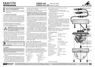
1 2 3 4 5 6 7 8<br />
GREEN —ON<br />
RED —STAND-BY<br />
SUB<br />
LEVEL<br />
MIN MAX<br />
POWER<br />
230 V~ / 50 Hz /300VA<br />
SUB<br />
CROSSOVER<br />
100 Hz<br />
50 Hz 150 Hz<br />
SUB-BOOST<br />
FREQUENCY LEVEL<br />
40 Hz<br />
30 Hz 50 Hz<br />
0 + 6dB<br />
SUB<br />
PHASE<br />
0° 180°<br />
<strong>SAM</strong>-2 ACTIVE <strong>SUBWOOFER</strong> <strong>MODUL</strong>E<br />
250W<br />
T3.15AL<br />
HIGH LEVEL INPUT<br />
LEFT RIGHT<br />
RIGHT<br />
LEFT<br />
SAT<br />
CROSSOVER<br />
100 Hz<br />
50 Hz 150 Hz<br />
GND LIFT<br />
GROUND<br />
LIFT<br />
LINE IN SAT OUT<br />
www.monacor.com<br />
9 10 11 12 13 14 15
D<br />
A<br />
CH<br />
4<br />
Auf der ausklappbaren Seite 3 finden Sie alle be -<br />
schriebenen Bedienelemente und Anschlüsse.<br />
1 Übersicht der Bedienelemente<br />
und Anschlüsse<br />
1 LED für den Betriebszustand<br />
rot = Stand-by (Bereitschaft)<br />
grün = Endstufe eingeschaltet<br />
2 Kühlkörper, kann im Betrieb unter Volllast bis 60 °C<br />
heiß werden<br />
Der Kühlkörper muss ungehindert Wärme abstrahlen<br />
können. Bei Überhitzung schaltet das Modul<br />
auf Stand-by.<br />
3 Regler SUB LEVEL zum Einstellen der Lautstärke<br />
4 Regler SUB CROSSOVER zum Einstellen der<br />
oberen Grenzfrequenz für den Subwoofer<br />
5 Regler SUB-BOOST FREQUENCY zum Einstellen<br />
der Frequenz für die Bassanhebung<br />
6 Regler SUB-BOOST LEVEL zum Einstellen der<br />
Bassanhebung bis maximal +6 dB<br />
7 Regler SUB PHASE zum Einstellen der Phasenlage<br />
für den Subwoofer<br />
8 Regler SAT CROSSOVER zum Einstellen der<br />
unteren Grenzfrequenz des Hochpasses für den<br />
Ausgang SAT OUT (14)<br />
9 Ein-/Ausschalter POWER<br />
10 Netzbuchse zum Anschluss an eine Steckdose<br />
(230 V~/50 Hz) über das beiliegende Netzkabel<br />
11 Sicherungshalter;<br />
eine durchgebrannte Sicherung nur durch eine<br />
gleichen Typs ersetzen<br />
12 Buchsen HIGH LEVEL INPUT für den Signaleingang<br />
zum Anschluss an die Lautsprecherausgänge<br />
eines Endverstärkers;<br />
alternativ zu den Cinch-Buchsen LINE IN (13)]<br />
13 Cinch-Buchsen LINE IN für ein Eingangssignal mit<br />
Line-Pegel;<br />
alternativ zu den Buchsen HIGH LEVEL INPUT (12)<br />
14 Cinch-Buchsen SAT OUT, Signalausgang mit Line-<br />
Pegel zum Anschluss an eine Stereoendstufe für<br />
die Satellitenlautsprecher<br />
15 Groundlift-Schalter<br />
Taste nicht gedrückt<br />
Signalmasse und Frontplatte/Schutzleiter sind<br />
getrennt<br />
Taste gedrückt<br />
Signalmasse und Frontplatte/Schutzleiter sind<br />
elektrisch verbunden<br />
2 Hinweise für den sicheren Gebrauch<br />
Das Gerät entspricht allen relevanten Richtlinien der<br />
EU und ist deshalb mit gekennzeichnet.<br />
WARNUNG Das Modul wird mit lebensgefährlicher<br />
Netzspannung (230 V~) be trieben. Achten<br />
Sie beim Einbau in eine Lautsprecherbox<br />
unbedingt darauf, dass das<br />
Modul nicht mit der Netzspannung verbunden<br />
ist. Den Netzstecker aus der<br />
Steckdose ziehen! Anderenfalls besteht<br />
die Gefahr eines lebensgefährlichen<br />
Schlages.<br />
Beachten Sie auch unbedingt die folgenden Punkte:<br />
● Das Modul ist nur zur Verwendung im Innenbreich<br />
geeignet. Schützen Sie es vor Tropf- und Spritz wasser,<br />
hoher Luftfeuchtigkeit und Hitze (zulässiger Einsatztemperaturbereich<br />
0 – 40 °C).<br />
● Stellen Sie keine mit Flüssigkeit gefüllten Gefäße,<br />
z. B. Trinkgläser, auf die Lautsprecherbox.<br />
● Nach dem Einbau des Moduls wird die in der Lautsprecherbox<br />
entstehende Wärme durch die Kühlrippen<br />
(2) abgegeben. De cken Sie diese deshalb nicht<br />
ab. Stellen Sie die Box nie direkt an eine Wand; halten<br />
Sie einen entsprechenden Ab stand ein.<br />
● Nehmen Sie das Modul nicht in Betrieb und ziehen<br />
Sie sofort den Netzstecker aus der Steckdose:<br />
1. wenn sichtbare Schäden am Modul oder an der<br />
Netz anschlussleitung vorhanden sind,<br />
2. wenn nach einem Sturz oder Ähnlichem der Verdacht<br />
auf einen Defekt besteht,<br />
3. wenn Funktionsstörungen auftreten.<br />
Lassen Sie das Modul in jedem Fall in einer Fachwerkstatt<br />
reparieren.<br />
● Ziehen Sie den Netzstecker nie am Kabel aus der<br />
Steckdose, fassen Sie immer am Stecker an.<br />
● Verwenden Sie für die Reinigung nur ein trockenes,<br />
weiches Tuch, niemals Wasser oder Chemikalien.<br />
● Wird das Modul zweckentfremdet, nicht richtig montiert,<br />
falsch angeschlossen bzw. be dient oder nicht<br />
fachgerecht re pa riert, kann keine Haftung für daraus<br />
resultierende Sach- oder Personenschäden und<br />
keine Garantie für das Modul übernommen werden.<br />
Soll das Gerät endgültig aus dem Betrieb<br />
genommen werden, übergeben Sie es zur<br />
umweltgerechten Entsorgung einem örtlichen<br />
Recyclingbetrieb.<br />
3 Verwendungsmöglichkeiten<br />
Das Einbaumodul <strong>SAM</strong>-2 ist eine komplett aufgebaute<br />
200-W-Verstärkerendstufe mit Netzteil und für den Einbau<br />
in eine 4-Ω- oder 8-Ω-Lautsprecherbox konzipiert.<br />
Durch die integrierte 18-dB-Subwoofer-Fre quenz -<br />
weiche lässt sich eine Aktiv-Subwoofer-Box realisieren.<br />
Das Modul und der angeschlossene Lautsprecher
werden durch ein 24-dB-Subsonic-Filter und umfassende<br />
Schutzschaltungen geschützt (gegen Kurzschluss,<br />
Überhitzung und Gleichspannungsüberlagerung<br />
am Ausgang).<br />
Der besondere Vorteil des <strong>SAM</strong>-2 ist, dass es als<br />
fertig montierter Aktiv-Subwoofer an jeder Stelle im<br />
Hörraum aufgestellt werden kann. Durch Regler für<br />
den Pegel und die Phasenlage lässt es sich optimal an<br />
die Satellitenlautsprecher anpassen.<br />
4 Montage<br />
WARNUNG<br />
Während der Montage darf der Baustein<br />
auf keinen Fall mit der Netzspannung<br />
verbunden sein!<br />
1) Für den Einbau des Moduls in die Lautsprecherbox<br />
einen Ausschnitt von 155 × 340 mm sägen. Die<br />
erforderliche Einbautiefe beträgt bei nicht versenkter<br />
Frontplatte 85 mm.<br />
2) Es dürfen nur Lautsprecher bzw. Lautsprechersys -<br />
teme mit einer Gesamtimpedanz von mindestens<br />
4 Ω angeschlossen werden. Den Lautsprecher<br />
über Flachstecker mit den Anschlüssen OUT+ und<br />
OUT- links oben auf der Leiterplatte der Endstufe<br />
verbinden. Dabei auf die richtige Polung achten,<br />
d. h. den Lautsprecherpluspol an den Kontakt<br />
OUT+ an schließen.<br />
3) Das Modul mit zehn M4-Schrauben an der Box<br />
festschrauben.<br />
5 Geräte anschließen<br />
Vor dem Anschluss bzw. vor dem Ändern bestehender<br />
Anschlüsse die Aktivbox ausschalten.<br />
5.1 Eingänge<br />
Das Modul <strong>SAM</strong>-2 hat zwei Eingänge zur Verfügung:<br />
1. Die Cinch-Buchsen LINE IN (13) für Signale mit<br />
Line-Pegel zum Anschluss von z. B. Vorverstärker,<br />
Mischpult, Equalizer, Effektgerät usw.<br />
2. Die Apparatebuchsen HIGH LEVEL INPUT (12) für<br />
den Anschluss an die Lautsprecherausgänge eines<br />
Endverstärkers.<br />
Wichtig: Werden die Apparatebuchsen verwendet,<br />
darf die Ausgangsleistung des angeschlossenen<br />
Endverstärkers nicht 480 W pro Kanal an 4-Ω-<br />
Lautsprechern bzw. 240 W pro Kanal an 8-Ω-<br />
Lautsprechern überschreiten, sonst kommt es<br />
durch Übersteuerung zu Signalverzerrungen.<br />
Am einfachsten und sichersten ist der Anschluss an<br />
den Buchsen LINE IN (13). Nur wenn kein Line-Signal<br />
zur Verfügung steht, sollten die Eingänge HIGH<br />
LEVEL INPUT (12) verwendet werden. Diese Eingänge<br />
über Lautsprecherkabel an die Lautsprecherausgänge<br />
eines Endverstärkers anschließen.<br />
Vorsicht beim Anschluss über die<br />
Apparatebuchsen!<br />
a. Bei Endverstärkern mit einer höheren Ausgangs -<br />
leis tung als oben angegeben, liegt berührungsgefährliche<br />
Spannung an den Buchsen HIGH LEVEL<br />
INPUT an.<br />
b. Bei einem versehentlichen Kurzschluss kann der<br />
Endverstärker beschädigt werden.<br />
c. Beim Anschluss auf die richtige Polung achten:<br />
Jeweils den Pluspol (gekennzeichnete Lautsprecherkabelader)<br />
mit der roten Apparatebuchse verbinden.<br />
5.2 Ausgänge<br />
Die Cinch-Buchsen SAT OUT (14) mit den Eingängen<br />
einer Stereoendstufe verbinden, welche die Satellitenlautsprecher<br />
betreibt.<br />
Bei hochwertigen, auftrennbaren Vollverstärkern<br />
mit einem geregelten Vorverstärker-Ausgang (mög liche<br />
Beschriftung „Pre Out“) und einem Endstufen-Eingang<br />
(mögliche Beschriftung „Amp In“) kann das<br />
Modul <strong>SAM</strong>-2 auch in den Vollverstärker eingeschleift<br />
werden: Die Buchsen LINE IN (13) an den Vorverstärker-Ausgang<br />
anschließen und die Buchsen SAT OUT<br />
(14) an den Endstufen-Eingang.<br />
5.3 Stromversorgung<br />
Zum Schluss das beiliegende Netzkabel zuerst in die<br />
Netzbuchse (10) stecken und dann in eine Steckdose<br />
(230 V~/50 Hz).<br />
6 Bedienung<br />
Alle Einstellungen und Klangbeurteilungen können nur<br />
in Verbindung mit den Satellitenlautsprechern erfolgen.<br />
Der Klang sollte am endgültigen Hörplatz beurteilt<br />
und durch eine zweite Person am Aktiv-Subwoofer<br />
nach Anweisung optimal angepasst werden.<br />
1) Mit dem Schalter POWER (9) die Aktivbox einschalten.<br />
Solange kein Eingangssignal anliegt, ist<br />
die Box im stromsparenden Bereitschaftsmodus<br />
(Stand-by) und die Kontroll-LED (1) leuchtet rot.<br />
Sobald ein Signal anliegt, schaltet die Endstufe ein<br />
und die LED leuchtet grün.<br />
Liegt länger als ca. 7 Minuten kein Signal an,<br />
schaltet die Aktivbox wieder auf Bereitschaft zurück<br />
(LED = rot). Wird die Aktivbox längere Zeit nicht<br />
benutzt, sollte sie mit dem Schalter POWER ausgeschaltet<br />
werden. Anderenfalls wird im Bereitschaftsmodus<br />
stets ein geringer Strom verbraucht.<br />
Sollte das automatische Umschalten zwischen<br />
Stand-by und Betrieb nicht optimal funktionieren,<br />
lässt sich die Einschaltschwelle im Bereich von<br />
1 – 10 mV verändern. Der Regler für die Einschaltschwelle<br />
befindet sich in der Position RVa auf der<br />
Vorverstärker-Leiterplatte. Je weiter der Regler im<br />
Uhrzeigersinn gedreht wird, desto höher muss der<br />
Eingangspegel sein, bei dem das Modul einschaltet.<br />
D<br />
A<br />
CH<br />
5
D<br />
A<br />
CH<br />
6<br />
2) Ist durch den Anschluss eine Masseschleife entstanden,<br />
tritt ein Brummen auf (z. B. bei leisen Musikpassagen).<br />
Diese Masseschleife lässt sich mit dem<br />
Groundlift-Schalter (15) unterbrechen. Anderseits ist<br />
der Verstärker nicht gegen elektrische Störfelder<br />
abgeschirmt, wenn die Frontplatte nicht an Masse<br />
liegt. Im Zweifelsfall den Schalter wechselweise<br />
schalten, um die optimale Einstellung zu finden.<br />
3) Mit dem Regler SUB CROSSOVER (4) die Trennfrequenz<br />
für den Subwoofer einstellen, d. h. die<br />
Frequenz, die nicht mehr durch den Subwoofer<br />
wiedergegeben werden soll (je niedriger die Trennfrequenz,<br />
desto schwerer die akustische Ortung<br />
des Sub woofers; je höher die Trennfrequenz, desto<br />
stärker die Bass unterstützung). In den meisten Fällen<br />
werden Regal- und kleine Standlautsprecher<br />
optimal er gänzt, wenn die eingestellte Trennfrequenz<br />
zwischen 60 Hz und 100 Hz liegt.<br />
4) Das Lautstärkeverhältnis zu den übrigen Lautsprechern<br />
mit dem Regler SUB LEVEL (3) einstellen.<br />
So lässt sich eine natürliche oder eine bewusst verstärkte<br />
Basswiedergabe einstellen.<br />
5) Die Phasenlage für den Subwoofer mit dem Regler<br />
SUB PHASE (7) einstellen. Diese Einstellung ist je<br />
nach den akustischen Gegebenheiten stärker oder<br />
schwächer wahrnehmbar. Am besten lässt sich die<br />
Einstellung bei einem Musikstück mit einem E-Bass,<br />
einem Kontrabass oder einer tiefen Bassstimme<br />
vornehmen. Den Regler SUB PHASE auf lauteste<br />
Basswiedergabe einstellen. Danach bei Bedarf den<br />
Regler SUB LEVEL wieder etwas zu rückdrehen.<br />
6) Mit dem Regler SUB-BOOST LEVEL (6) können<br />
bestimmte Frequenzen im Tiefbassbereich bis zu<br />
6 dB angehoben werden. Die Frequenz für die<br />
Bass anhebung mit dem Regler SUB-BOOST FRE-<br />
QUENCY (5) einstellen.<br />
7) Mit dem Regler SAT CROSSOVER (8) die Trennfrequenz<br />
für die Satellitenlautsprecher einstellen,<br />
d. h. die Frequenz, die nicht mehr durch die Satellitenlautsprecher<br />
wiedergegeben werden soll. Da -<br />
durch wird der Verstärker für die Satellitenlautsprecher<br />
von den tiefen Frequenzen entlastet.<br />
7 Schutzschaltungen<br />
Zum Schutz der Endstufe des <strong>SAM</strong>-2 und des angeschlossenen<br />
Subwoofers sind verschiedene Schutzschaltungen<br />
vorhanden:<br />
1. Bei einem Kurzschluss oder einer Gleichspannungsüberlagerung<br />
am Ausgang für den Sub woofer<br />
schaltet das Modul sofort auf Stand-by. Das<br />
Modul mit dem Schalter POWER (9) ausschalten<br />
und die Fehlerursache durch Fachpersonal beheben<br />
lassen. Die Schutzschaltung wird durch das<br />
Ausschalten zurückgesetzt.<br />
2. Bei Überhitzung schaltet das Modul ebenfalls auf<br />
Stand-by. Der Kühlkörper (2) muss besser belüftet<br />
werden. Nach dem Abkühlen auf normale Betriebstemperatur<br />
schaltet das Modul wieder ein.<br />
8 Technische Daten<br />
Sinusausgangsleistung<br />
an 4-Ω-Lautsprecher: . . . 200 WRMS<br />
an 8-Ω-Lautsprecher: . . . 125 WRMS<br />
Musikausgangsleistung<br />
an 4-Ω-Lautsprecher: . . . 250 WMAX<br />
an 8-Ω-Lautsprecher: . . . 180 WMAX<br />
Frequenzbereich<br />
Subwoofer-Ausgang<br />
untere Grenzfrequenz: . 20 Hz<br />
obere Grenzfrequenz: . . 50 – 150 Hz einstellbar<br />
Ausgang SAT OUT<br />
untere Grenzfrequenz: . 50 – 150 Hz einstellbar<br />
obere Grenzfrequenz: . . 20 kHz<br />
Tiefbassanhebung: . . . . . . . bis +6 dB / 30 – 50 Hz<br />
Klirrfaktor: . . . . . . . . . . . . . . < 0,1 %<br />
Störabstand: . . . . . . . . . . . . > 70 dB<br />
min. Anschlussimpedanz<br />
für den Subwoofer: . . . . . . . 4 Ω<br />
Eingänge<br />
LINE IN: . . . . . . . . . . . . . . max. 4,2 V/ 20 kΩ<br />
HIGH LEVEL INPUT: . . . . max. 44 V/ 17 kΩ<br />
entspricht<br />
480 W an 4 Ω bzw.<br />
240 W an 8 Ω<br />
Stromversorgung: . . . . . . . . 230 V~ / 50 Hz<br />
Leistungsaufnahme<br />
bei Volllast: . . . . . . . . . . . 300 VA<br />
im Leerlauf: . . . . . . . . . . . 19 VA<br />
in Stand-by: . . . . . . . . . . . 6 VA<br />
Einschaltautomatik<br />
Einschaltschwelle: . . . . . . 1 – 10 mV<br />
Stand-by-Aktivierung: . . . nach ca. 7 Minuten<br />
ohne Eingangssignal<br />
Einsatztemperatur: . . . . . . . . 0 – 40 °C<br />
Abmessungen (B × H × T): . 185 × 370 × 89 mm<br />
erforderl. Boxenausschnitt: . 155 × 340 mm<br />
Einbautiefe ohne Frontplatte: 85 mm<br />
Gewicht: . . . . . . . . . . . . . . . . 4,9 kg<br />
Änderungen vorbehalten.<br />
Diese Bedienungsanleitung ist urheberrechtlich für<br />
MONACOR ® INTERNATIONAL GmbH & Co. KG ge -<br />
schützt. Eine Reproduktion für eigene kommerzielle<br />
Zwecke – auch auszugsweise – ist untersagt.
All operating elements and connections described<br />
can be found on the fold-out page 3.<br />
1 Operating Elements and Connections<br />
1 Power LED for operating mode<br />
red = stand-by<br />
green = power amplifier switched on<br />
2 Heat sink, may heat up to 60 °C under full load<br />
The heat sink must be allowed to dissipate heat<br />
without any obstruction. In case of overheating, the<br />
module will go on stand-by.<br />
3 Control SUB LEVEL for adjusting the volume<br />
4 Control SUB CROSSOVER for adjusting the upper<br />
limit frequency for the subwoofer<br />
5 Control SUB-BOOST FREQUENCY for adjusting<br />
the frequency for the bass boost<br />
6 Control SUB-BOOST LEVEL for adjusting the bass<br />
boost up to +6 dB max.<br />
7 Control SUB PHASE for adjusting the phase for the<br />
subwoofer<br />
8 Control SAT CROSSOVER for adjusting the lower<br />
limit frequency of the high pass for the output SAT<br />
OUT (14)<br />
9 POWER switch<br />
10 Mains jack for connecting a mains socket (230 V~/<br />
50 Hz) via the supplied mains cable<br />
11 Fuse holder;<br />
always replace a burnt-out fuse by one of the same<br />
type only<br />
12 Jacks HIGH LEVEL INPUT for the signal input for<br />
connecting the speaker outputs of a power amplifier<br />
[as an alternative to the phono jacks LINE IN<br />
(13)]<br />
13 Phono jacks LINE IN for an input signal with line<br />
level [as an alternative to the jacks HIGH LEVEL<br />
INPUT (12)]<br />
14 Phono jacks SAT OUT, signal output with line level<br />
for connecting a stereo power amplifier for the sa t -<br />
ellite speakers<br />
15 Groundlift switch<br />
button not pressed<br />
signal ground and front plate/earthed conductor<br />
are separated<br />
button pressed<br />
signal ground and front plate/earthed conductor<br />
are electrically connected<br />
2 Safety Notes<br />
The unit corresponds to all relevant directives of the<br />
EU and is therefore marked with .<br />
WARNING The unit uses dangerous mains voltage<br />
(230 V~). Never connect the module to<br />
the mains voltage when installing it into<br />
a speaker cabinet. Disconnect the plug<br />
from the mains socket, otherwise you<br />
will risk an electric shock which may be<br />
dangerous to life!<br />
Please observe the following items in any case:<br />
● The module is suitable for indoor use only. Protect it<br />
against dripping water and splash water, high air<br />
humidity, and heat (admissible ambient temperature<br />
range 0 – 40 °C).<br />
● Do not place any vessel filled with liquid on the unit,<br />
e. g. a drinking glass.<br />
● After installing the module, the heat generated in the<br />
speaker cabinet is carried off by the cooling ribs (2).<br />
Therefore, the cooling ribs must not be covered.<br />
Never place the cabinet directly on a wall; a sufficient<br />
distance must be kept.<br />
● Do not operate the module or immediately disconnect<br />
the plug from the mains socket<br />
1. if there is visible damage to the module or to the<br />
mains cable,<br />
2. if a defect might have occurred after the unit was<br />
dropped or suffered a similar accident,<br />
3. if malfunctions occur.<br />
In any case the unit must be repaired by skilled personnel.<br />
● Never pull the mains cable when disconnecting the<br />
mains plug from the socket, always seize the plug.<br />
● For cleaning only use a dry, soft cloth; never use<br />
chemicals or water.<br />
● No guarantee claims for the module or liability for<br />
any resulting personal damage or material damage<br />
will be accepted if the module is used for other purposes<br />
than originally intended, if it is not correctly<br />
installed, connected or operated, or if it is not repaired<br />
in an expert way.<br />
If the unit is to be put out of operation definitively,<br />
take it to a local recycling plant for a<br />
disposal which is not harmful to the environment.<br />
3 Applications<br />
The insertion module <strong>SAM</strong>-2 is a fully assembled<br />
200 W power amplifier with integrated power supply<br />
unit designed for installation into 4 Ω or 8 Ω speaker<br />
cabinets. Due to the integrated 18 dB subwoofer cross -<br />
over network, an active subwoofer system can be created.<br />
The module and the speaker connected are protected<br />
by a 24 dB subsonic filter and comprehensive<br />
GB<br />
7
GB<br />
8<br />
protective circuits (against short circuit, overheat ing,<br />
and direct voltage content at the output).<br />
It is the particular advantage of <strong>SAM</strong>-2 that it can be<br />
placed anywhere in the room as a fully assembled<br />
active subwoofer. Level and phase controls allow optimum<br />
matching to the satellite speakers.<br />
4 Installation<br />
WARNING<br />
During installation, the module must<br />
never be connected to the mains voltage!<br />
1) For installing the module into the speaker cabinet,<br />
saw a cutout of 155 × 340 mm. If the front panel is<br />
not recessed, the required mounting depth is 85 mm.<br />
2) Only connect speakers or speaker systems of a<br />
total impedance of at least 4 Ω. Use push-on terminals<br />
to connect the speaker to the connections<br />
OUT+ and OUT- on the top left of the PCB of the<br />
power amplifier. Observe the correct polarity, i. e.<br />
connect the positive pole of the speaker to the contact<br />
OUT+.<br />
3) Use ten M4 screws to screw the module to the cabinet.<br />
5 Connection<br />
Always switch off the active speaker system prior to<br />
making or changing any connections.<br />
5.1 Inputs<br />
The module <strong>SAM</strong>-2 is equipped with two inputs:<br />
1. The phono jacks LINE IN (13) for signals with line<br />
level for connecting e. g. preamplifier, mixer, equalizer,<br />
effect unit, etc.<br />
2. The binding posts HIGH LEVEL INPUT (12) for<br />
connecting the speaker outputs of a power amplifier.<br />
Important: If the binding posts are used, the output<br />
power of the power amplifier connected must not<br />
exceed 480 W per channel at 4 Ω speakers or<br />
240 W per channel at 8 Ω speakers, otherwise<br />
there will be signal distortions due to overload.<br />
Connection to the jacks LINE IN (13) is the easiest and<br />
safest solution. The inputs HIGH LEVEL INPUT (12)<br />
should only be used if no line signal is available. Use<br />
speaker cables to connect these inputs to the speaker<br />
outputs of a power amplifier.<br />
Be careful when connecting via the binding posts!<br />
a. In case of power amplifiers with a higher output<br />
power than indicated above, there will be a hazard<br />
of contact as dangerous voltage is applied to the<br />
jacks HIGH LEVEL INPUT.<br />
b. In case of accidental short circuit, the power amplifier<br />
may be damaged.<br />
c. Observe the correct polarity for connection: Connect<br />
the corresponding positive pole (speaker<br />
cable core with marking) to the red binding post.<br />
5.2 Outputs<br />
Connect the phono jacks SAT OUT (14) to the inputs<br />
of a stereo power amplifier operating the satellite<br />
speakers.<br />
In case of separable full amplifiers of high quality<br />
provided with a controlled preamplifier output (possibly<br />
marked “Pre Out”) and a power amplifier input (possibly<br />
marked “Amp In”), it is also possible to insert the<br />
module <strong>SAM</strong>-2 into the full amplifier: Connect the<br />
jacks LINE IN (13) to the preamplifier output and the<br />
jacks SAT OUT (14) to the power amplifier output.<br />
5.3 Power supply<br />
Finally connect the supplied mains cable first to the<br />
mains jack (10) and then to a mains socket (230 V~/<br />
50 Hz).<br />
6 Operation<br />
Any adjustments and sound evaluations must only be<br />
made in connection with the satellite speakers. The<br />
sound should be evaluated at the final place of hearing<br />
where a second person at the active subwoofer should<br />
be instructed to perform an optimum adjustment.<br />
1) Switch on the active speaker system with the<br />
switch POWER (9). As long as no input signal is<br />
available, the system is in the power-saving standby<br />
mode and the indicating LED (1) shows red. As<br />
soon as an input signal is available, the power<br />
amplifier is switched on and the LED shows green.<br />
If no signal is available for more than approx.<br />
7 minutes, the active speaker system returns<br />
to stand-by (LED = red). If the active speaker system<br />
is not used for a longer period, it should be<br />
switched off with the switch POWER, otherwise the<br />
stand-by mode will always have a low current consumption.<br />
If the automatic switchover between stand-by<br />
and operation does not function optimally, the<br />
switch-on threshold can be modified in the range of<br />
1 – 10 mV. The control for the switch-on threshold is<br />
in the position RVa on the PCB of the preamplifier.<br />
The further the control is turned clockwise, the<br />
higher the required input level at which the module<br />
will be switched on.<br />
2) If a ground loop has been created by the connection,<br />
humming will occur (e. g. with music passages<br />
of low volume). This ground loop can be interrupted<br />
with the groundlift switch (15). On the other hand,<br />
the amplifier is not screened against electric noise<br />
fields if the front plate is not grounded. In case of<br />
doubt, set the switch alternately to find the optimum<br />
adjustment.
3) Use the control SUB CROSSOVER (4) to adjust<br />
the upper limit frequency, i. e. the frequency which<br />
is not to be reproduced any more by the subwoofer<br />
(the lower the upper limit frequency, the more difficult<br />
the acoustic localization of the subwoofer; the<br />
higher the limit frequency, the more powerful the<br />
bass support). In most cases, shelf speakers and<br />
small free-standing speakers are optimally completed<br />
with a limit frequency adjusted between<br />
60 Hz and 100 Hz.<br />
4) Adjust the volume ratio to the other speakers with<br />
the control SUB LEVEL (3). Thus, a natural or a<br />
deliberately amplified bass reproduction can be<br />
adjusted.<br />
5) Adjust the phase for the subwoofer with the control<br />
SUB PHASE (7). According to the acoustic condi -<br />
tions, this adjustment is more or less audible. The<br />
phase can best be adjusted during a music piece<br />
with an electric bass, a contrabass, or a deep bass<br />
voice. Set the control SUB PHASE to the bass<br />
reproduction of the highest volume. Slightly turn<br />
back the control SUB LEVEL, if required.<br />
6) Use the control SUB-BOOST LEVEL (6) to boost<br />
certain frequencies in the low bass range up to<br />
6 dB. Adjust the frequency for the bass boost with<br />
the control SUB-BOOST FREQUENCY (5).<br />
7) Adjust the lower limit frequency for the satellite<br />
speakers with the control SAT CROSSOVER (8),<br />
i. e. the frequency not to be reproduced any more<br />
by the satellite speakers. Thus, the amplifier for the<br />
satellite speakers will be relieved from the low frequencies.<br />
7 Protective Circuits<br />
For protecting the power amplifier of <strong>SAM</strong>-2 and the<br />
subwoofer connected, various protective circuits are<br />
provided:<br />
1. In case of a short circuit or direct voltage content at<br />
the output for the subwoofer, the module will immediately<br />
go on stand-by. Switch off the module with<br />
the switch POWER (9) and ask skilled personnel to<br />
eliminate the problem. Switching off the module will<br />
reset the protective circuit.<br />
2. In case of overheating, the module will also go on<br />
stand-by. Ventilation of the heat sink (2) must be<br />
improved. After cooling down to normal operating<br />
temperature, the module will be switched on again.<br />
8 Specifications<br />
RMS output power<br />
at 4 Ω speaker: . . . . . . . . 200 WRMS<br />
at 8 Ω speaker: . . . . . . . . 125 WRMS<br />
Music output power<br />
at 4 Ω speaker: . . . . . . . . 250 WRMS<br />
at 8 Ω speaker: . . . . . . . . 180 WRMS<br />
Frequency range<br />
subwoofer output<br />
lower limit frequency: . . 20 Hz<br />
upper limit frequency: . . 50 – 150 Hz adjustable<br />
output SAT OUT<br />
lower limit frequency: . . 50 – 150 Hz adjustable<br />
upper limit frequency: . . 20 kHz<br />
Low bass boost: . . . . . . . . . . up to +6 dB/30 – 50 Hz<br />
THD: . . . . . . . . . . . . . . . . . . < 0.1 %<br />
S/N ratio: . . . . . . . . . . . . . . . > 70 dB<br />
Min. load impedance<br />
for the subwoofer: . . . . . . . . 4 Ω<br />
Inputs<br />
LINE IN: . . . . . . . . . . . . . . max. 4.2 V/20 kΩ<br />
HIGH LEVEL INPUT: . . . . max. 44 V/17 kΩ<br />
corresponds to<br />
480 W at 4 Ω or<br />
240 W at 8 Ω<br />
Power supply: . . . . . . . . . . . 230 V~/50 Hz<br />
Power consumption<br />
at full load: . . . . . . . . . . . . 300 VA<br />
at no-load: . . . . . . . . . . . . 19 VA<br />
on stand-by: . . . . . . . . . . . 6 VA<br />
Automatic switch-on<br />
Switch-on threshold: . . . . 1 – 10 mV<br />
Stand-by activation: . . . . . after approx. 7 minutes<br />
without input signal<br />
Ambient temperature: . . . . . 0 – 40 °C<br />
Dimensions (W × H × D): . . . 185 × 370 × 89 mm<br />
Required cabinet cutout: . . . 155 × 340 mm<br />
Mounting depth<br />
without front panel: . . . . . . . 85 mm<br />
Weight: . . . . . . . . . . . . . . . . . 4.9 kg<br />
Subject to technical modification.<br />
All rights reserved by MONACOR ® INTERNATIONAL<br />
GmbH & Co. KG. No part of this instruction manual<br />
may be reproduced in any form or by any means for<br />
any commercial use.<br />
GB<br />
9
F<br />
B<br />
CH<br />
10<br />
Vous trouverez sur la page 3, dépliable, la description<br />
des éléments et branchements.<br />
1 Eléments et branchements<br />
1 LED témoin de fonctionnement<br />
rouge = Stand-by (veille)<br />
verte = amplificateur allumé<br />
2 Refroidisseur : peut chauffer jusquʼà 60 °C pendant<br />
le fonctionnement sous charge pleine<br />
Le refroidisseur doit pouvoir dégager la chaleur<br />
sans aucun empêchement ; en cas de surchauffe,<br />
le module se met sur Stand-by (veille).<br />
3 Réglage SUB LEVEL pour régler le volume<br />
4 Réglage SUB CROSSOVER pour régler la fréquence<br />
limite supérieure pour le subwoofer<br />
5 Réglage SUB-BOOST FREQUENCY pour régler<br />
la fréquence pour lʼaugmentation des graves<br />
6 Réglage SUB-BOOST LEVEL pour régler lʼaugmentation<br />
des graves jusquʼà +6 dB max.<br />
7 Réglage SUB PHASE pour régler la phase pour le<br />
subwoofer<br />
8 Réglage SAT CROSSOVER pour régler la fréquence<br />
limite inférieure du passe-haut pour la sortie<br />
SAT OUT (14)<br />
9 Interrupteur POWER marche/arrêt<br />
10 Prise secteur pour relier le module via le cordon<br />
secteur livré à une prise secteur 230 V~/50 Hz<br />
11 Porte fusible :<br />
tout fusible fondu doit être remplacé exclusivement<br />
par un fusible de même type<br />
12 Prises HIGH LEVEL INPUT pour lʼentrée signal à<br />
relier aux sorties haut-parleurs dʼun amplificateur<br />
[alternative aux prises RCA LINE IN (13)]<br />
13 Prises RCA LINE IN pour un signal dʼentrée à<br />
niveau ligne [alternative aux prises HIGH LEVEL<br />
INPUT (12)]<br />
14 Prises RCA SAT OUT, sortie signal avec niveau<br />
ligne pour brancher à un amplificateur stéréo pour<br />
les haut-parleurs satellites.<br />
15 Interrupteur Groundlift<br />
touche non enfoncée :<br />
la masse du signal et la face avant/conducteur<br />
de protection sont séparés<br />
touche enfoncée :<br />
la masse du signal et la face avant/conducteur<br />
de protection sont reliés électriquement<br />
2 Conseils dʼutilisation et de sécurité<br />
Lʼappareil répond à toutes les directives nécessaires<br />
de lʼUnion européenne et porte donc le symbole .<br />
ATTENTION Le module est alimenté par une tension<br />
dangereuse 230 V~. Lors de lʼinstallation<br />
dans une enceinte, veillez<br />
impérativement à ce que le module ne<br />
soit pas relié à la tension dʼalimentation<br />
secteur. Dé branchez le cordon<br />
secteur de la prise secteur ; sinon vous<br />
pourriez subir une décharge électrique<br />
dangereuse.<br />
Respectez scrupuleusement les points suivants :<br />
● Le module nʼest conçu que pour une utilisation en<br />
intérieur. Protégez-le de tout type de projections<br />
dʼeau, des éclaboussures, dʼune humidité élevée et<br />
de la chaleur (plage de température de fonctionnement<br />
autorisée : 0 – 40 °C).<br />
● En aucun cas, vous ne devez poser dʼobjet contenant<br />
du liquide ou un verre sur lʼenceinte.<br />
● Une fois le module installé, la chaleur dégagée dans<br />
lʼenceinte est évacuée par le refroidisseur (2). En<br />
aucun cas, il ne doit être couvert. Ne placez jamais<br />
lʼenceinte directement contre un mur ; conservez<br />
une certaine distance de sécurité.<br />
● Ne faites jamais fonctionner le module et débranchez-le<br />
immédiatement lorsque :<br />
1. des dommages sur le module ou sur le cordon<br />
secteur apparaissent.<br />
2. après une chute ou accident similaire..., lʼappareil<br />
peut présenter un défaut.<br />
3. des dysfonctionnements apparaissent.<br />
Dans tous les cas, les dommages doivent être réparés<br />
par un technicien spécialisé.<br />
● Ne débranchez jamais lʼappareil en tirant sur le cordon<br />
secteur ; retirez toujours le cordon secteur en<br />
tirant la fiche.<br />
● Pour nettoyer le module, utilisez uniquement un<br />
chiffon sec et doux, en aucun cas de produits chimiques<br />
ou dʼeau.<br />
● Nous déclinons toute responsabilité en cas de dommages<br />
corporels ou matériels résultants si le module<br />
est utilisé dans un but autre que celui pour lequel il a<br />
été conçu, sʼil nʼest pas correctement branché, utilisé,<br />
sʼil nʼest pas réparé par une personne habilitée ;<br />
de même, la garantie deviendrait caduque.<br />
Lorsque lʼappareil est définitivement retiré du<br />
service, vous devez le déposer dans une<br />
usine de recyclage de proximité pour contribuer<br />
à son élimination non polluante.<br />
3 Possibilités dʼutilisation<br />
Le module <strong>SAM</strong>-2 à encastrer est un amplificateur<br />
200 W complet avec bloc dʼalimentation et conçu pour<br />
être placé dans une enceinte 4 Ω ou 8 Ω. Il est pos-
sible de réaliser une enceinte active subwoofer grâce<br />
au filtre subwoofer 18 dB intégré. Le module et le hautparleur<br />
relié sont protégés par un filtre subsonique<br />
24 dB et de nombreux circuits de protection (contre les<br />
courts-circuits, surchauffes et présence de tension<br />
continue en sortie).<br />
Lʼavantage premier du <strong>SAM</strong>-2 est sa faculté à se<br />
placer à nʼimporte quel endroit dans la pièce dʼécoute<br />
comme subwoofer actif déjà monté. Par les réglages<br />
pour le niveau et la phase, il peut être adapté de<br />
manière optimale aux haut-parleurs satellites.<br />
4 Montage<br />
AVERTISSEMENT<br />
Pendant le montage, le module<br />
ne doit en aucun cas être relié à<br />
la tension secteur !<br />
1) Pour le montage du module dans lʼébénisterie de<br />
lʼenceinte, sciez une découpe de 155 × 340 mm ; la<br />
profondeur de montage nécessaire est de 85 mm si<br />
la face avant nʼest pas encastrée.<br />
2) Seuls des haut-parleurs ou systèmes de haut-parleurs<br />
dʼune impédance totale de 4 Ω au moins peuvent<br />
être branchés. Reliez le haut-parleur via des<br />
fiches plates aux bornes OUT+ et OUT- à gauche<br />
en haut sur la platine de lʼamplificateur. Veillez à<br />
respecter la polarité, cʼest-à-dire à relier le pôle<br />
plus haut-parleur au contact OUT+.<br />
3) Vissez le module sur lʼébénisterie avec 10 vis M4.<br />
5 Branchements des appareils<br />
Avant dʼeffectuer les branchements ou de modifier les<br />
branchements existants, éteignez lʼenceinte active.<br />
5.1 Entrées<br />
Le module <strong>SAM</strong>-2 dispose de deux entrées :<br />
1. les prises RCA LINE IN (13) pour les signaux à<br />
niveau ligne pour brancher par exemple préamplificateur,<br />
table de mixage, égaliseur, appareil à effets<br />
spéciaux etc.<br />
2. les prises HIGH LEVEL INPUT (12) pour brancher<br />
aux sorties haut-parleurs dʼun amplificateur.<br />
Important : si les prises HIGH LEVEL INPUT sont<br />
utilisées, la puissance de sortie de lʼamplificateur<br />
relié ne doit pas dépasser 480 W par canal pour<br />
des haut-parleurs 4 Ω ou 240 W par canal pour des<br />
haut-parleurs 8 Ω sinon la surcharge pourrait générer<br />
des distorsions de signal.<br />
Le plus simple et le plus sûr est de privilégier le branchement<br />
aux prises LINE IN (13). Les entrées HIGH<br />
LEVEL INPUT (12) ne doivent être utilisées que si<br />
aucun signal ligne nʼest disponible. Reliez ces entrées<br />
via des câbles haut-parleurs aux sorties haut-parleurs<br />
dʼun amplificateur.<br />
Attention lors du branchement aux prises HIGH<br />
LEVEL INPUT<br />
a. Sur des amplificateurs avec une puissance de sortie<br />
plus élevée que celle citée ci-dessus, une tension<br />
dangereuse est présente aux prises HIGH<br />
LEVEL INPUT.<br />
b. En cas de court-circuit inopiné accidentel, lʼamplificateur<br />
peut être endommagé.<br />
c. Lors du branchement, veillez à respecter la polarité<br />
; reliez respectivement le pôle plus (conducteur<br />
du câble haut-parleur repéré) à la prise rouge.<br />
5.2 Sorties<br />
Reliez les prises RCA SAT OUT (14) aux entrées dʼun<br />
amplificateur stéréo qui fait fonctionner les haut-parleurs<br />
satellites.<br />
Pour des amplificateurs séparables de grande qualité,<br />
avec une sortie préampli réglée (repère possible<br />
“Pre Out”) et une entrée amplificateur (repère possible<br />
“Amp In ”), le module <strong>SAM</strong>-2 peut être inséré également<br />
dans lʼamplificateur : branchez les prises LINE<br />
IN (13) à la sortie préampli et les prises SAT OUT (14)<br />
à lʼentrée de lʼamplificateur.<br />
5.3 Alimentation<br />
Reliez maintenant le cordon secteur livré à la prise<br />
dʼalimentation (10) puis lʼautre extrémité à une prise<br />
secteur 230 V~/50 Hz.<br />
6 Fonctionnement<br />
Lʼensemble des réglages et évaluations de tonalité ne<br />
peut être effectué quʼen liaison avec les haut-parleurs<br />
satellites. Il convient dʼapprécier la sonorité dans le<br />
lieu définitif dʼécoute et de lʼadapter, grâce à une<br />
seconde personne placée au niveau du subwoofer<br />
actif, de manière optimale.<br />
1) Avec lʼinterrupteur POWER (9), allumez lʼenceinte<br />
active. Tant quʼaucun signal dʼentrée nʼest présent,<br />
lʼenceinte est en mode veille, économiseur de courant<br />
(Stand-by) et la LED de contrôle (1) brille et est<br />
rouge. Dès quʼun signal est appliqué, lʼamplificateur<br />
sʼallume et la LED devient verte.<br />
Si aucun signal nʼest présent pendant 7 minutes<br />
environ, lʼenceinte active revient en mode veille<br />
(Stand-by, LED = rouge). Si lʼenceinte active nʼest<br />
pas utilisée pendant un temps certain, vous devez<br />
lʼéteindre avec lʼinterrupteur POWER ; sinon, en<br />
mode veille, un courant faible est toujours<br />
consommé.<br />
Si la commutation automatique entre les modes<br />
Stand-By et fonctionnement ne devait pas fonctionner<br />
de manière optimale, le seuil de commutation<br />
peut être modifié dans la plage de 1 à 10 mV. Le<br />
réglage du seuil est dans la position RVa sur le circuit<br />
imprimé du préamplificateur. Plus le réglage<br />
est tourné dans le sens des aiguilles dʼune montre,<br />
plus le niveau dʼentrée, pour lequel le module sʼallume,<br />
doit être élevé.<br />
F<br />
B<br />
CH<br />
11
F<br />
B<br />
CH<br />
12<br />
2) Si par le branchement un bouclage de masse<br />
apparaît, un ronflement se produit (par exemple<br />
lors de passages de musique à faible volume). Ce<br />
bouclage de masse peut être interrompu par lʼinterrupteur<br />
Groundlift (15). Dʼautre part, lʼamplificateur<br />
nʼest pas blindé contre les interférences électriques<br />
si la face avant nʼest pas reliée à la masse. En cas<br />
de doute, mettez lʼinterrupteur alternativement pour<br />
trouver le réglage optimal.<br />
3) Avec le réglage SUB CROSSOVER (4), réglez la<br />
fréquence limite supérieure cʼest-à-dire la fréquence<br />
qui ne doit plus être restitutée par le subwoofer<br />
(plus la fréquence limite supérieure est<br />
faible, plus la localisation acoustique du subwoofer<br />
est difficile ; plus la fréquence limite est élevée, plus<br />
le soutien des graves est important). Dans la majorité<br />
des cas, les haut-parleurs de bibliothèque ou<br />
les petits haut-parleurs fixes sont complétés de<br />
manière optimale si la fréquence limite réglée est<br />
entre 60 Hz et 100 Hz.<br />
4) Réglez le rapport de volume des haut-parleurs restants<br />
avec le réglage SUB LEVEL (3) ; on peut ainsi<br />
régler une restitution naturelle ou délibérément<br />
amplifiée des graves.<br />
5) Réglez la phase pour le subwoofer avec le réglage<br />
SUB PHASE (7). Selon les conditions acoustiques,<br />
ce réglage est audible plus fortement ou plus faiblement<br />
; le réglage sʼeffectue le mieux pour un<br />
morceau de musique avec une basse électrique,<br />
une contrebasse ou une voix grave. Réglez le<br />
réglage SUB PHASE sur la restitution des graves la<br />
plus forte. Ensuite, selon les besoins, tournez le<br />
réglage SUB LEVEL en arrière.<br />
6) Avec le réglage SUB-BOOST LEVEL (6), on peut<br />
augmenter certaines fréquences dans la plage des<br />
graves jusquʼà 6 dB. Réglez la fréquence pour<br />
lʼaugmentation des graves avec le réglage SUB-<br />
BOOST FREQUENCY (5).<br />
7) Avec le réglage SAT CROSSOVER (8), réglez la<br />
fréquence limite inférieure pour les haut-parleurs<br />
satellites, cʼest-à-dire la fréquence qui ne doit pas<br />
être restituée par les haut-parleurs satellites. Ainsi<br />
lʼamplificateur pour les haut-parleurs satellites est<br />
déchargé des fréquences graves.<br />
7 Circuits de protection<br />
Pour protéger lʼamplificateur du <strong>SAM</strong>-2 et le subwoofer<br />
relié, plusieurs circuits de protection sont prévus :<br />
1. En cas de court-circuit ou de présence de tension<br />
continue en sortie pour le subwoofer, le module<br />
passe immédiatement sur Stand-by. Eteignez le<br />
module avec lʼinterrupteur POWER (9) et demandez<br />
à un technicien spécialisé de régler le problème.<br />
Le circuit de protection est réinitialisé par<br />
lʼarrêt de lʼappareil.<br />
2. En cas de surchauffe, le module passe également en<br />
Stand-by ; le refroidisseur (2) doit être mieux aéré.<br />
Après le refroidissement et avec une température de<br />
fonctionnement normale, le module se rallume.<br />
8 Caractéristiques techniques<br />
Puissance de sortie RMS<br />
Haut-parleurs 4 Ω : . . . . . 200 WRMS<br />
Haut-parleurs 8 Ω : . . . . . 125 WRMS<br />
Puissance de sortie maximale<br />
Haut-parleurs 4 Ω : . . . . . 250 WMAX<br />
Haut-parleurs 8 Ω : . . . . . 180 WMAX<br />
Bande passante<br />
Sortie subwoofer<br />
Fréquence<br />
limite inférieure : . . . . . . 20 Hz<br />
Fréquence<br />
limite supérieure : . . . . . 50 – 150 Hz réglable<br />
Sortie SAT OUT<br />
Fréquence<br />
limite inférieure : . . . . . . 50 – 150 Hz réglable<br />
Fréquence<br />
limite supérieure : . . . . . 20 kHz<br />
Augmentation<br />
des graves : . . . . . . . . . . . . . jusquʼà +6 dB/30 – 50 Hz<br />
Taux de distorsion : . . . . . . . < 0,1 %<br />
Rapport signal/bruit : . . . . . . > 70 dB<br />
Impédance minimale<br />
de branchement<br />
pour le subwoofer : . . . . . . . 4 Ω<br />
Entrées<br />
LINE IN : . . . . . . . . . . . . . max. 4,2 V/20 kΩ<br />
HIGH LEVEL INPUT : . . . max. 44 V/17 kΩ<br />
correspond à<br />
480 W sous 4 Ω ou<br />
240 W sous 8 Ω<br />
Alimentation : . . . . . . . . . . . . 230 V~/50 Hz<br />
Consommation<br />
Charge pleine : . . . . . . . . 300 VA<br />
A vide : . . . . . . . . . . . . . . . 19 VA<br />
En stand-by (veille) : . . . . 6 VA<br />
Allumage automatique<br />
Seuil de commutation : . . 1 – 10 mV<br />
Activation stand-by : . . . . 7 minutes environ sans<br />
signal dʼentrée<br />
Température fonc. : . . . . . . . 0 – 40 °C<br />
Dimensions (L × H × P) : . . . 185 × 370 × 89 mm<br />
Découpe nécessaire : . . . . . 155 × 340 mm<br />
Profondeur montage<br />
sans face avant : . . . . . . . . . 85 mm<br />
Poids : . . . . . . . . . . . . . . . . . 4,9 kg<br />
Tout droit de modification réservé.<br />
Notice dʼutilisation protégée par le copyright de<br />
MONACOR ® INTERNATIONAL GmbH & Co. KG.<br />
Toute reproduction même partielle à des fins commerciales<br />
est interdite.
A pagina 3, se aperta completamente, vedrete<br />
sempre gli elementi di comando e i collegamenti<br />
descritti.<br />
1 Elementi di comando e collegamenti<br />
1 LED per lo stato di funzionamento<br />
rosso = stand-by<br />
verde = stadio finale acceso<br />
2 Dissipatore di calore; a pieno carico può riscaldarsi<br />
fino a 60 °C<br />
Il dissipatore di calore deve poter dissipare il calore<br />
senza ostacoli. In caso di surriscaldamento, il<br />
modulo va in stand-by.<br />
3 Regolatore SUB LEVEL per impostare il volume<br />
4 Regolatore SUB CROSSOVER per impostare la<br />
frequenza superiore di taglio per il subwoofer<br />
5 Regolatore SUB-BOOST FREQUENCY per im po -<br />
stare la frequenza per lʼaumento dei bassi<br />
6 Regolatore SUB-BOOST LEVEL per impostare<br />
lʼaumento dei bassi fino a +6 dB max.<br />
7 Regolatore SUB PHASE per impostare la fase per<br />
il subwoofer<br />
8 Regolatore SAT CROSSOVER per impostare la<br />
frequenza inferiore di taglio del passaalto per<br />
lʼuscita SAT OUT (14)<br />
9 Interruttore on/off POWER<br />
10 Presa di rete per il collegamento con una presa<br />
(230 V~/50 Hz) per mezzo del cavo rete in dotazione<br />
11 Portafusibili;<br />
sostituire un fusibile difettoso sempre con uno dello<br />
stesso tipo<br />
12 Prese HIGH LEVEL INPUT per lʼingresso del se -<br />
gnale per il collegamento con le uscite per altoparlanti<br />
di un amplificatore finale [in alternativa alle<br />
prese RCA LINE IN (13)]<br />
13 Prese RCA LINE IN per un segnale dʼingresso con<br />
livello Line [in alternativa alle prese HIGH LEVEL<br />
INPUT (12)]<br />
14 Prese RCA SAT OUT, uscita segnale con livello<br />
Line per il collegamento con uno stadio finale stereo<br />
per gli altoparlanti satelliti<br />
15 Interruttore Groundlift<br />
Tasto non premuto<br />
Massa del segnale e pannello frontale/conduttore<br />
di terra sono separati<br />
Tasto premuto<br />
Massa del segnale e pannello frontale/conduttore<br />
di terra sono collegati elettricamente<br />
2 Avvertenze di sicurezza<br />
Questʼapparecchio è conforme a tutte le direttive rilevanti<br />
dellʼUE e pertanto porta la sigla .<br />
AVVERTIMENTO Il modulo funziona con pericolosa<br />
tensione di rete (230 V~).<br />
Durante il montaggio in una<br />
cassa acustica fare attenzione<br />
che il modulo non venga collegato<br />
con la tensione di rete. Staccare<br />
la spina di rete dalla presa!<br />
Altrimenti si può verificare una<br />
scossa pericolosa.<br />
Da osservare anche i seguenti punti:<br />
● Far funzionare il modulo solo allʼinterno di locali.<br />
Proteggerlo dallʼacqua gocciolante e dagli spruzzi<br />
dʼacqua, da alta umidità dellʼaria e dal calore (temperatura<br />
dʼimpiego ammessa fra 0 e 40 °C).<br />
● Non depositare sulla cassa acustica dei contenitori<br />
riempiti di liquidi, p. es. bicchieri.<br />
● Dopo il montaggio del modulo, il calore che si crea<br />
dentro la cassa acustica viene dissipata dai dissipatori<br />
di calore (2). Non coprire i dissipatori. Non collocare<br />
la cassa direttamente contro una parete, ma<br />
mantenere una certa distanza.<br />
● Non mettere in funzione il modulo e staccare subito<br />
la spina rete se:<br />
1. il modulo o il cavo rete presentano dei danni visibili;<br />
2. dopo una caduta o dopo eventi simili sussiste il<br />
sospetto di un difetto;<br />
3. il modulo non funziona correttamente.<br />
Per la riparazione rivolgersi sempre ad unʼofficina<br />
competente.<br />
● Staccare il cavo rete afferrando la spina, senza ti -<br />
rare il cavo.<br />
● Per la pulizia usare solo un panno morbido, asciutto;<br />
non impiegare in nessun caso prodotti chimici o<br />
acqua.<br />
● Nel caso dʼuso improprio, do montaggio scorretto, di<br />
collegamenti sbagliati, di impiego scorretto o di riparazione<br />
scorretta non si assume nessuna respon sabilità<br />
per eventuali danni consequenziali a persone o<br />
a cose e cessa ogni diritto di garanzia.<br />
Se si desidera eliminare lʼapparecchio definitivamente,<br />
consegnarlo per lo smaltimento<br />
ad unʼistituzione locale per il riciclaggio.<br />
3 Possibilità dʼimpiego<br />
Il modulo <strong>SAM</strong>-2 è uno stadio finale di amplificatore<br />
200 W, completamente montato, con alimentatore, ed<br />
è stato realizzato per il montaggio in una cassa acustica<br />
a 4 Ω o 8 Ω. Grazie al filtro subwoofer integrato di<br />
18 dB, è possibile creare una cassa subwoofer attiva.<br />
I<br />
13
I<br />
14<br />
Il modulo e lʼaltoparlante collegato sono protetti da un<br />
filtro subsonico di 24 dB e da ampi circuiti di protezione<br />
(contro cortocircuito, surriscaldamento e sovrapposizione<br />
di tensione continua allʼuscita).<br />
Il particolare vantaggio del <strong>SAM</strong>-2 è il fatto che<br />
come subwoofer attivo completamente montato, può<br />
essere collocato in qualsiasi punto della sala. Con i<br />
regolatori per il livello e per la fase può essere adattato<br />
in modo ottimale agli altoparlanti satelliti.<br />
4 Montaggio<br />
AVVERTIMENTO<br />
1) Per il montaggio del modulo in una cassa acustica,<br />
preparare unʼapertura di 155 × 340 mm. Con il pannello<br />
frontale non incassato, la profondità di montaggio<br />
è di 85 mm.<br />
2) Si possono collegare solo altoparlanti o sistemi di<br />
altoparlanti con unʼimpedenza globale di 4 Ω mini -<br />
mo. Collegare lʼaltoparlante mediante connettori<br />
piatti con i contatti OUT+ e OUT- a sinistra in alto<br />
sulla scheda dello stadio finale, osservando la corretta<br />
polarità: collegare il positivo dellʼaltoparlante<br />
con il contatto OUT+.<br />
3) Avvitare il modulo nella cassa con dieci viti M4.<br />
5 Collegare gli apparecchi<br />
Prima di effettuare o modificare i collegamenti spegnere<br />
il modulo attivo.<br />
5.1 Ingressi<br />
Durante il montaggio, il modulo<br />
non devʼessere collegato in nessun<br />
caso con la tensione di rete!<br />
Il modulo <strong>SAM</strong>-2 dispone di due ingressi:<br />
1. Le prese RCA LINE IN (13) per segnali con livello<br />
Line per il collegamento p. es. di un preamplificatore,<br />
mixer, equalizzatore, unità per effetti ecc.<br />
2. Le prese per apparecchi HIGH LEVEL INPUT (12)<br />
per il collegamento con le uscite degli altoparlanti di<br />
un amplificatore finale.<br />
Importante: Se si usano le prese per apparecchi,<br />
la potenza dʼuscita dellʼamplificatore finale collegato<br />
non deve superare i 480 W per canale con<br />
altoparlanti a 4 Ω, e i 240 W con altoparlanti a 8 Ω,<br />
per escludere distorsioni per sovrapilotaggio.<br />
Il collegamento più sicuro e più semplice è quello con<br />
le prese LINE IN (13). Gli ingressi HIGH LEVEL INPUT<br />
(12) si dovrebbero utilizzare solo se non è disponibile<br />
nessun segnale Line. Collegare questi ingressi con le<br />
uscite per altoparlanti di un amplificatore servendosi di<br />
cavi per altoparlanti.<br />
Fare attenzione nel collegare le prese per apparecchi!<br />
a. Negli amplificatori finali con potenza dʼuscita superiore<br />
a quella indicata sopra, alle prese HIGH<br />
LEVEL INPUT è presente una tensione pericolosa<br />
per il contatto.<br />
b. In caso di cortocircuito accidentale, lʼamplificatore<br />
finale può subire dei danni.<br />
c. Durante il collegamento, fare attenzione alla corretta<br />
polarità: collegare il positivo (il conduttore contrassegnato)<br />
con il terminale rosso.<br />
5.2 Uscite<br />
Collegare le prese RCA SAT OUT (14) con gli ingressi<br />
di uno stadio finale stereo che gestisce gli altoparlanti<br />
satelliti.<br />
Negli amplificatori di qualità con uscita preamplificatore<br />
regolata (marcata eventualmente “Pre Out”) e<br />
con un ingresso stadio finale (marcato eventualmente<br />
“Amp In”), il modulo <strong>SAM</strong>-2 può essere inserito anche<br />
nellʼamplificatore: collegare le prese LINE IN (13) con<br />
lʼuscita preamplificatore e le prese SAT OUT (14) con<br />
lʼingresso dello stadio finale.<br />
5.3 Alimentazione<br />
Alla fine inserire il cavo rete in dotazione prima nella<br />
presa (10) e quindi in una presa di rete (230 V~/50 Hz).<br />
6 Funzionamento<br />
Tutte le impostazioni e giudizi sul suono sono possibili<br />
solo in collegamento con gli altoparlanti satelliti. Il<br />
suono dovrebbe essere valutato sul posto di ascolto<br />
definitivo e una seconda persona dovrebbe effettuare<br />
gli adattamenti sul subwoofer attivo seguendo le indicazioni<br />
di chi giudica lʼascolto.<br />
1) Accendere la cassa attiva con lʼinterruttore<br />
POWER (9). Finché non è presente nessun segna -<br />
le dʼingresso, la cassa si trova nella modalità economica<br />
di stand-by e il LED di controllo (1) è rosso.<br />
Non appena è presente un segnale, lo stadio finale<br />
si accende e il LED diventa verde.<br />
Se per oltre 7 minuti manca il segnale, la cassa<br />
attiva ritorna nella modalità di stand-by (LED =<br />
rosso). Se non viene usata per un periodo prolungato,<br />
conviene spegnerla con lʼinterruttore POWER<br />
perché in stand-by consuma comunque sempre un<br />
poʼ di corrente.<br />
Se la commutazione automatica fra stand-by e<br />
funzionamento non dovesse funzionare in modo<br />
ottimale, è possibile modificare la soglia dʼinserzione<br />
fra 1 e 10 mV. Il regolatore per la soglia dʼinserzione<br />
si trova in posizione RVa sul circuito integrato<br />
del preamplificatore. Più si gira il regolatore in<br />
senso orario, più deve essere alto il livello dʼingresso<br />
con il quale il modulo reagisce.
2) Se il collegamento ha provocato un anello di terra si<br />
sente un ronzio (p. es. con la musica a basso<br />
volume). Tale anello può essere interrotto con lʼinterruttore<br />
Groundlift (15). Però, lʼamplificatore non<br />
è protetto contro interferenze elettriche se il pannello<br />
frontale con è collegato con la massa. Nel<br />
dubbio si deve provare quale posizione dellʼinterruttore<br />
è la migliore.<br />
3) Impostare la frequenza superiore di taglio con il re -<br />
golatore SUB CROSSOVER (4), cioè la frequenza<br />
che non deve più essere riprodotta dal subwoofer<br />
(più è bassa la frequenza superiore di ta glio, più è<br />
difficile localizzare il subwoofer per lʼudito; più è alta<br />
tale frequenza, più forti sono i bassi). Nella maggior<br />
parte dei casi, gli altoparlanti inseriti negli scaffali o<br />
i piccoli altoparlanti vengono integrati in modo ottimale<br />
se la frequenza di taglio è impostata fra 60 Hz<br />
e 100 Hz.<br />
4) Impostare il volume rispetto agli altri altoparlanti<br />
con il regolatore SUB LEVEL (3). In questo modo è<br />
possibile trovare una riproduzione dei bassi naturale<br />
o volutamente forte.<br />
5) Impostare le fasi per il subwoofer con il regolatore<br />
SUB PHASE (7). Questa impostazione è percepibile<br />
più o meno forte a seconda della situazione acustica.<br />
Lʼimpostazione è più facile con un brano con<br />
basso elettronico, con un contrabbasso o con una<br />
voce umana bassa. Impostare il regolatore SUB<br />
PHASE sulla riproduzione più forte dei bassi, quindi<br />
abbassare se necessario il regolatore SUB LEVEL.<br />
6) Con il regolatore SUB-BOOST LEVEL (6) si possono<br />
aumentare fino a 6 dB determinate frequenze<br />
nei bassi. Impostare la frequenza per lʼaumento dei<br />
bassi con il regolatore SUB-BOOST FREQUENCY<br />
(5).<br />
7) Impostare la frequenza inferiore di taglio per gli<br />
altoparlanti satelliti con il regolatore SAT CROSS -<br />
OVER (8), ovvero la frequenza che non deve più<br />
esser riprodotta dagli altoparlanti satelliti. In questo<br />
modo, lʼamplificatore per gli altoparlanti satelliti<br />
viene liberato delle frequenze basse.<br />
7 Circuiti di protezione<br />
Per proteggere lo stadio finale del <strong>SAM</strong>-2 e del<br />
subwoofer collegato, sono presenti diversi circuiti di<br />
protezione:<br />
1. Nel caso di un cortocircuito o di sovrapposizione di<br />
tensione continua allʼuscita per il subwoofer, il<br />
modulo passa subito nella modalità di stand-by.<br />
Spegnere il modulo con lʼinterruttore POWER (9) e<br />
fare eliminare il difetto da una persona esperta.<br />
Con lo spegnimento, il circuito di protezione viene<br />
resettato.<br />
2. Anche nel caso di surriscaldamento il modulo<br />
passa subito nella modalità di stand-by. In questo<br />
caso occorre ventilare meglio il dissipatore di<br />
calore (2). Dopo il raffreddamento a temperatura<br />
normale dʼesercizio, il modulo si attiva da solo.<br />
8 Dati tecnici<br />
Potenza efficace<br />
con altoparlanti 4 Ω: . . . . . 200 WRMS<br />
con altoparlanti 8 Ω: . . . . . 125 WRMS<br />
Potenza musicale<br />
con altoparlanti 4 Ω: . . . . . 250 WMAX<br />
con altoparlanti 8 Ω: . . . . . 180 WMAX<br />
Gamma di frequenze<br />
Uscita subwoofer<br />
frequenza inf. di taglio: . . 20 Hz<br />
frequenza sup. di taglio: . 50 – 150 Hz regolabile<br />
Uscita SAT OUT<br />
frequenza inf. di taglio: . . 50 – 150 Hz regolabile<br />
frequenza sup. di taglio: . 20 kHz<br />
Aumento bassi: . . . . . . . . . . fino a +6 dB/30 – 50 Hz<br />
Fattore di distorsione: . . . . . < 0,1 %<br />
Rapporto S/R: . . . . . . . . . . . > 70 dB<br />
Impedenza min.<br />
di collegamento<br />
per il subwoofer: . . . . . . . . . 4 Ω<br />
Ingressi<br />
LINE IN: . . . . . . . . . . . . . . max. 4,2 V/20 kΩ<br />
HIGH LEVEL INPUT: . . . . max. 44 V/ 17 kΩ<br />
corrispondente a<br />
480 W con 4 Ω o<br />
240 W con 8 Ω<br />
Alimentazione: . . . . . . . . . . . 230 V~/50 Hz<br />
Assorbimento<br />
a pieno carico: . . . . . . . . . 300 VA<br />
a vuoto: . . . . . . . . . . . . . . 19 VA<br />
in stand-by: . . . . . . . . . . . 6 VA<br />
Inserzione automatica<br />
Soglia dʼinserzione: . . . . . 1 – 10 mV<br />
Attivazione stand-by: . . . . dopo 7 minuti ca. senza<br />
segnale dʼingresso<br />
Temperatura dʼesercizio: . . . 0 – 40 °C<br />
Dimensioni (l × h × p): . . . . . 185 × 370 × 89 mm<br />
Apertura nella cassa: . . . . . . 155 × 340 mm<br />
Profondità di montaggio<br />
senza pannello frontale: . . . . 85 mm<br />
Peso: . . . . . . . . . . . . . . . . . . 4,9 kg<br />
Con riserva di modifiche tecniche.<br />
La MONACOR ® INTERNATIONAL GmbH & Co. KG si<br />
riserva ogni diritto di elaborazione in qualsiasi forma<br />
delle presenti istruzioni per lʼuso. La riproduzione –<br />
anche parziale – per propri scopi commerciali è vietata.<br />
I<br />
15
NL<br />
B<br />
16<br />
Op de uitklapbare pagina 3 vindt u een overzicht<br />
van de bedieningselementen en de aansluitingen.<br />
1 Overzicht van de bedieningselementen<br />
en aansluitingen<br />
1 LED voor de bedrijfstoestand<br />
rood = stand-by (startklaar)<br />
groen = eindversterker ingeschakeld<br />
2 Koellichaam, kan in bedrijf bij volle belasting tot<br />
60 °C warm worden<br />
Het koellichaam moet ongehinderd warmte kunnen<br />
afstralen. Bij oververhitting schakelt de module<br />
naar stand-by.<br />
3 Regelaar SUB LEVEL om het volume in te stellen<br />
4 Regelaar SUB CROSSOVER om de bovenste<br />
grensfrequentie voor de subwoofer in te stellen<br />
5 Regelaar SUB-BOOST FREQUENCY om de frequentie<br />
voor de basversterking in te stellen<br />
6 Regelaar SUB-BOOST LEVEL om de basversterking<br />
op maximaal +6 dB in te stellen<br />
7 Regelaar SUB PHASE om de faseverhouding voor<br />
de subwoofer in te stellen<br />
8 Regelaar SAT CROSSOVER om de onderste frequentiegrens<br />
van het hoogdoorlaatfilter in te stellen<br />
voor de uitgang SAT OUT (14)<br />
9 POWER-schakelaar<br />
10 Netjack voor de aansluiting op een stopcontact<br />
(230 V~/50 Hz) via het meegeleverde netsnoer<br />
11 Zekeringhouder;<br />
vervang een gesmolten zekering uitsluitend door<br />
een zekering van hetzelfde type<br />
12 Jacks HIGH LEVEL INPUT voor de signaalingang<br />
om de eindversterker op de luidsprekeruitgangen<br />
aan te sluiten [alternatief voor de cinch-jacks LINE<br />
IN (13)]<br />
13 Cinch-jacks LINE IN voor een ingangssignaal met<br />
lijnniveau [alternatief voor de jacks HIGH LEVEL*<br />
INPUT (12)]<br />
14 Cinch-jacks SAT OUT, signaaluitgang met lijnniveau<br />
om de satellietluidsprekers aan te sluiten op<br />
een stereo-eindversterker<br />
15 Massaschakelaar<br />
Toets niet ingedrukt<br />
Signaalmassa en frontpaneel/aarding zijn ge -<br />
scheiden<br />
Toets ingedrukt<br />
Signaalmassa en frontpaneel/aarding zijn elektrisch<br />
verbonden<br />
2 Veiligheidsvoorschriften<br />
Het apparaat is in overeenstemming met alle relevante<br />
EU-Richtlijnen en is daarom gekenmerkt met .<br />
WAARSCHUWING De netspanning (230 V~) van de<br />
module is levensgevaarlijk. Let<br />
er bij de inbouw in een luidsprekerkast<br />
in elk geval op, dat de<br />
module niet op de netspanning<br />
is aange sloten. Trek de netstekker<br />
uit het stopcontact! Anders<br />
loopt u het risico van een levensgevaarlijke<br />
elektrische schok.<br />
Let eveneens op het volgende:<br />
● De module is enkel geschikt voor gebruik binnenshuis.<br />
Vermijd druip- en spatwater, uitzonderlijk war me<br />
plaatsen en plaatsen met een hoge vochtigheid (toegestaan<br />
omgevingstemperatuurbereik: 0 – 40 °C).<br />
● Plaats geen bekers met vloeistof (b. v. drinkglazen)<br />
op de luidsprekerkast.<br />
● Na de inbouw van de module wordt de in de luidsprekerkast<br />
ontstane warmte via de koelribben (2)<br />
afgegeven. Dek ze daarom niet af. Plaats de box<br />
niet direct tegen een muur; zorg dat er voldoende<br />
afstand tussen de muur en de box is.<br />
● Schakel de module niet in resp. trek onmiddellijk de<br />
stekker uit het stopcontact:<br />
1. wanneer de module of het netsnoer zichtbaar<br />
beschadigd zijn,<br />
2. wanneer er een defect zou kunnen optreden<br />
nadat de module bijvoorbeeld gevallen is,<br />
3. wanneer de module slecht functioneert.<br />
De module moet in elk geval hersteld worden door<br />
een gekwalificeerd vakman.<br />
● Trek de stekker nooit met het snoer uit het stopcontact,<br />
maar met de stekker zelf.<br />
● Verwijder het stof met een droge, zachte doek.<br />
Gebruik zeker geen water of chemicaliën.<br />
● In geval van ongeoorloofd of verkeerd gebruik, verkeerde<br />
montage, foutieve aansluiting resp. bediening<br />
of van herstelling door een niet-gekwalificeerd<br />
persoon vervalt de garantie en de verantwoordelijkheid<br />
voor hieruit resulterende materiële of lichamelijke<br />
schade.<br />
Wanneer het apparaat definitief uit bedrijf<br />
wordt genomen, bezorg het dan voor milieuvriendelijke<br />
verwerking aan een plaatselijk<br />
recyclagebedrijf.<br />
3 Toepassingen<br />
De inbouwmodule <strong>SAM</strong>-2 is een volledig uitgeruste<br />
eindversterker van 200 W met voedingseenheid en<br />
bedoeld voor inbouw in een luidsprekerkast van 4 Ω of<br />
8 Ω. Door de scheidingsfilter van 18 dB in de subwoofer<br />
kunt u een actieve-subwoofer-box creëren. De<br />
module en de aangesloten luidspreker worden bevei-
ligd door een subsonisch filter van 24 dB en uitgebreide<br />
beveiligingscircuits (tegen kortsluiting, oververhitting<br />
en gelijkspanning op de uitgang).<br />
Het bijzondere voordeel van de <strong>SAM</strong>-2 is dat hij als<br />
gebruiksklaar gemonteerde actieve subwoofer overal<br />
in het luisterbereik kan worden opgesteld. Door regelaars<br />
voor het niveau en de faseverhouding kunt u<br />
hem optimaal op de satellietluidsprekers afstemmen.<br />
4 Montage<br />
WAARSCHUWING<br />
Tijdens de montage mag de<br />
module in geen geval met netspanning<br />
zijn verbonden!<br />
1) Om de module te kunnen inbouwen, zaagt u in de<br />
luidsprekerkast een uitsparing van 155 × 340 mm.<br />
De nodige inbouwdiepte bedraagt 85 mm; de frontplaat<br />
is dan niet verzonken.<br />
2) Er mogen uitsluitend luidsprekers resp. luidsprekersystemen<br />
worden aangesloten met een totale<br />
impedantie van minstens 4 Ω. Verbind de luidspreker<br />
via platte stekkers met de aansluitingen OUT+<br />
en OUT- links bovenaan de eindversterker. Let<br />
daarbij op de correcte polariteit, d. w. z. sluit de<br />
positieve pool van de luidspreker aan op het contact<br />
OUT+.<br />
3) Zet de module op de box vast met tien schroeven<br />
M4.<br />
5 Toestellen aansluiten<br />
Schakel de module uit, alvorens aansluitingen te<br />
maken resp. bestaande aansluitingen te wijzigen.<br />
5.1 Ingangen<br />
De module <strong>SAM</strong>-2 heeft twee ingangen ter beschikking:<br />
1. De cinch-jacks LINE IN (13) voor signalen met lijnniveau<br />
voor de aansluiting van b. v. voorversterkers,<br />
mengpanelen, equalizers, effectenapparaten etc.<br />
2. De apparaatjacks HIGH LEVEL INPUT (12) voor de<br />
aansluiting van een eindversterker op de luidsprekeruitgangen.<br />
Belangrijk: Bij gebruik van de apparaatjacks (12)<br />
mag het uitgangsvermogen van de aangesloten<br />
eindversterker niet hoger liggen dan 480 W per<br />
kanaal op luidsprekers van 4 Ω resp. 240 W per<br />
kanaal op luidsprekers van 8 Ω. Zo niet worden de<br />
signalen vervormd door oversturing.<br />
Het eenvoudigste en veiligste is een aansluiting op de<br />
jacks LINE IN (13). Uitsluitend wanneer er geen lijnsig -<br />
naal beschikbaar is, moet u de ingangen HIGH LEVEL<br />
INPUT (12) gebruiken. Verbind deze ingangen via<br />
luidsprekerkabels met de luidsprekeruitgangen van<br />
een eindversterker.<br />
Let op bij de aansluiting via de apparaatjacks!<br />
a. Bij eindversterkers met een hoger uitgangsvermogen<br />
dan hierboven aangegeven, staan de jacks<br />
HIGH LEVEL INPUT onder een levensgevaarlijke<br />
spanning.<br />
b. Bij een per ongeluk veroorzaakte kortsluiting kan<br />
de eindversterker worden beschadigd.<br />
c. Let bij de aansluiting op de correcte polariteit: Verbind<br />
de positieve pool (gemarkeerde ader van de<br />
luidsprekerkabel) telkens met de rode apparaatjack.<br />
5.2 Uitgangen<br />
Verbind de cinch-jacks SAT OUT (14) met de ingangen<br />
van een stereo-eindversterker die de satellietluidsprekers<br />
stuurt.<br />
Bij hoogwaardige, loskoppelbare krachtversterkers<br />
met een voorversterkeruitgang (mogelijk opschrift “Pre<br />
Out”) en een eindversterkeringang (mogelijk opschrift<br />
“Amp In”) kan de module <strong>SAM</strong>-2 ook op de krachtversterker<br />
worden aangesloten: Sluit de jacks LINE IN<br />
(13) aan op de voorversterkeruitgang en de jacks SAT<br />
OUT (14) op de eindversterkeringang.<br />
5.3 Voedingsspanning<br />
Ten slotte verbindt u het meegeleverde netsnoer eerst<br />
met de jack (10) en plugt u het in een stopcontact<br />
(230 V~/50 Hz).<br />
6 Bediening<br />
U kunt de instellingen pas controleren, wanneer de<br />
verbinding met de satellietluidsprekers tot stand is<br />
gebracht. De klank moet op de uiteindelijke luisterplaats<br />
worden beoordeeld en door een tweede persoon<br />
op de actieve subwoofer volgens aanwijzingen<br />
optimaal afgeregeld.<br />
1) Schakel de actieve box met de POWER-schakelaar<br />
(9) in. Zolang er geen ingangssignaal is, staat<br />
de box in energiesparende bedrijfsmodus (standby),<br />
en de controle-LED (1) licht rood op. Zodra er<br />
een signaal is, schakelt de eindversterker in en licht<br />
de LED groen op.<br />
Indien er gedurende ca. 7 minuten geen signaal<br />
is, schakelt de actieve box terug naar stand-bymodus<br />
(LED = rood). Indien de actieve box gedurende<br />
langere tijd niet wordt gebruikt, moet u hem<br />
met de POWER-schakelaar uitschakelen. Anders<br />
is er in de stand-by-modus steeds een klein<br />
stroomverbruik.<br />
Als het automatisch omschakelen tussen standbymodus<br />
en bedrijfsmodus niet optimaal zou<br />
functioneren, kunt u de inschakeldrempel in het<br />
bereik van 1 – 10 mV veranderen. De regelaar voor<br />
de inschakeldrempel bevindt zich in de positie RVa<br />
op de printplaat van de voorversterker. Hoe verder<br />
de regelaar naar rechts wordt gedraaid, hoe hoger<br />
het ingangsniveau moet zijn, waarbij de module<br />
inschakelt.<br />
NL<br />
B<br />
17
NL<br />
B<br />
18<br />
2) Indien de aansluiting een aardlus veroorzaakt, dan<br />
is er een bromgeluid hoorbaar (b. v. bij zachte<br />
muziekfragmenten). U kunt deze aardlus onderbreken<br />
met behulp van een massaschakelaar (15).<br />
Anderzijds is de versterker niet beschermd tegen<br />
elektrische storingsvelden, als het frontpaneel niet<br />
met de massa is verbonden. In geval van twijfel<br />
plaatst u de schakelaar afwisselend in beide standen<br />
om de optimale instelling te vinden.<br />
3) Stel met de regelaar SUB CROSSOVER (4) de<br />
bovenste grensfrequentie in, d. w. z. de frequentie<br />
die niet meer door de subwoofer mag worden weergegeven<br />
(hoe lager de bovenste grensfrequentie,<br />
hoe moeilijker de akoestische lokalisering van de<br />
subwoofer; hoe hoger de grensfrequentie, hoe sterker<br />
de basondersteuning). In de meeste gevallen<br />
worden boekenplankluidsprekers en kleine staan -<br />
de luidsprekers optimaal aangevuld, wanneer de<br />
grensfrequentie tussen 60 Hz en 100 Hz is ingesteld.<br />
4) Stel de volumeverhouding met de andere luidsprekers<br />
in met de regelaar SUB LEVEL (3). Zo kunt u<br />
een natuurlijke of een bewust versterkte basweergave<br />
instellen.<br />
5) Stel de faseverhouding voor de subwoofer in met<br />
de regelaar SUB PHASE (7). Deze instelling is volgens<br />
de akoestische omstandigheden sterker of<br />
zwakker waarneembaar. Het best gebeurt de<br />
instelling aan de hand van een muziekstuk met een<br />
elektronische bas, een contrabas of een diepe basstem.<br />
Stel de regelaar SUB PHASE in op de luidste<br />
basweergave. Draai de regelaar SUB LEVEL<br />
daarna terug indien nodig.<br />
6) Met de regelaar SUB-BOOST LEVEL (6) kunt u<br />
bepaalde frequenties in het diepebasbereik met<br />
maximum 6 dB versterken. Stel met de regelaar<br />
SUB-BOOST FREQUENCY (5) de frequentie in<br />
voor de basversterker.<br />
7) Stel met de regelaar SAT CROSSOVER (8) de<br />
onderste frequentiegrens voor de satellietluidsprekers<br />
in, d. w. z. de frequentie die niet meer door de<br />
satellietluidspreker mag worden weergegeven. Op<br />
deze manier ontlast u de versterker voor de satellietluidsprekers<br />
van de lage frequenties.<br />
7 Beveiligingscircuits<br />
Voor de bescherming van de eindversterker van de<br />
<strong>SAM</strong>-2 en de aangesloten subwoofer zijn er verschillende<br />
beveiligingscircuits beschikbaar:<br />
1. Bij een kortsluiting of een gelijkspanning op de uitgang<br />
voor de subwoofer schakelt de module<br />
onmiddellijk naar stand-by-modus: Schakel de<br />
module uit met de POWER-schakelaar (9) en laat<br />
de fout door deskundig personeel verhelpen. Het<br />
beveiligingscircuit wordt gereset door de vesterker<br />
uit en in te schakelen.<br />
2. Bij oververhitting schakelt de module eveneens<br />
naar stand-by-modus. Zorg voor een betere venti-<br />
latie van het koellichaam (2). Na afkoeling tot de<br />
normale bedrijfstemperatuur schakelt de module<br />
weer in.<br />
8 Technische gegevens<br />
Sinusvermogen (WRMS)<br />
op luidsprekers van 4 Ω: . 200 WRMS<br />
op luidsprekers van 8 Ω: . 125 WRMS<br />
Muziekvermogen<br />
op luidsprekers van 4 Ω: . 250 WMAX<br />
op luidsprekers van 8 Ω: . 180 WMAX<br />
Frequentiebereik<br />
Subwooferuitgang<br />
onderste<br />
grensfrequentie: . . . . . . 20 Hz<br />
bovenste<br />
grensfrequentie: . . . . . . 50 – 150 Hz instelbaar<br />
Uitgang SAT OUT<br />
onderste<br />
grensfrequentie: . . . . . . 50 – 150 Hz instelbaar<br />
bovenste<br />
grensfrequentie: . . . . . . 20 kHz<br />
Versterking van<br />
de diepe bastonen: . . . . . . . tot +6 dB/30 – 50 Hz<br />
THD: . . . . . . . . . . . . . . . . . . < 0,1 %<br />
Signaal/Ruis-verhouding: . . > 70 dB<br />
min. aansluitimpedantie<br />
voor de subwoofer: . . . . . . . 4 Ω<br />
Ingangen<br />
LINE IN: . . . . . . . . . . . . . . max. 4,2 V/20 kΩ<br />
HIGH LEVEL INPUT: . . . . max. 44 V/17 kΩ<br />
komt overeen met<br />
480 W op 4 Ω resp.<br />
240 W op 8 Ω<br />
Voedingsspanning: . . . . . . . 230 V~/50 Hz<br />
Vermogens-opname<br />
bij volle belasting: . . . . . . 300 VA<br />
bij nullast: . . . . . . . . . . . . . 19 VA<br />
in stand-by-modus: . . . . . 6 VA<br />
Automatische inschakeling<br />
Inschakeldrempel: . . . . . . 1 – 10 mV<br />
Activering stand-by-modus: na ca. 7 minuten zonder<br />
ingangssignaal<br />
Omgevingstemperatuurbereik:<br />
. . . . . . . . 0 – 40 °C<br />
Afmetingen (B × H × D): . . . 185 × 370 × 89 mm<br />
vereiste uitsparing in kast: . . 155 × 340 mm<br />
Inbouwdiepte<br />
zonder frontpaneel: . . . . . . . 85 mm<br />
Gewicht: . . . . . . . . . . . . . . . . 4,9 kg<br />
Wijzigingen voorbehouden.<br />
Deze gebruiksaanwijzing is auteursrechterlijk beschermd<br />
voor MONACOR ® INTERNATIONAL GmbH & Co. KG.<br />
Reproductie voor eigen commerciële doeleinden –<br />
ook bij wijze van uitzondering – is niet toegestaan.
Todos los elementos de funcionamiento y las<br />
conexiones que se describen pueden encontrarse<br />
en la página 3 desplegable.<br />
1 Elementos y conexiones<br />
1 LED testigo de funcionamiento<br />
rojo = stand-by (espera)<br />
verde = amplificador conectado<br />
2 Enfriador: puede calentarse durante el funcionamiento<br />
bajo carga llena hasta 60 °C<br />
El enfriador debe destacar el calor sin ninguna<br />
molestia, en caso de sobrecalentamiento, el<br />
módulo se conmute en stand-by.<br />
3 Reglaje SUB LEVEL para regular el volumen<br />
4 Reglaje SUB CROSSOVER para regular la frecuencia<br />
límite superior para el subwoofer<br />
5 Reglaje SUB-BOOST FREQUENCY para regular<br />
la frecuencia para el aumento de los graves<br />
6 Reglaje SUB-BOOST LEVEL para regular el<br />
aumento de los graves hasta +6 dB máx.<br />
7 Reglaje SUB PHASE para regular la fase para el<br />
subwoofer<br />
8 Reglaje SAT CROSSOVER para regular la frecuencia<br />
límite inferior del pasa alto para la salida<br />
SAT OUT (14)<br />
9 Interruptor POWER ON/OFF<br />
10 Toma de red para conectar el módulo vía el cable<br />
de conexión entregado a una toma de 230 V~/<br />
50 Hz<br />
11 Portafusible:<br />
todo fusible dañado debe cambiarse exclusivamente<br />
por un fusible de mismo tipo<br />
12 Tomas HIGH LEVEL INPUT para la entrada señal<br />
a conectar con las salidas altavoces de un amplificador<br />
[alternativa con las tomas RCA LINE IN (13)]<br />
13 Tomas RCA LINE IN para una señal de entrada<br />
con nivel línea [alternativa con las tomas HIGH<br />
LEVEL INPUT (12)]<br />
14 Tomas RCA SAT OUT, salida señal con nivel línea<br />
para conectar a un amplificador estéreo para los<br />
altavoces satélites<br />
15 Interruptor Groundlift<br />
tecla no pulsada<br />
la masa de la señal y la parte delantera/conductor<br />
protector son separadas<br />
tecla pulsada<br />
la masa de la señal y la parte delantera/conductor<br />
protector están conectado eléctricamente<br />
2 Consejos de utilización y seguridad<br />
El aparato cumple con todas las directivas relevantes por<br />
la UE y por lo tanto está marcado con el símbolo .<br />
ADVERTENCIA El módulo está alimentado por una<br />
tensión peligrosa 230 V~. Durante<br />
la in stalación en un recinto, verifique<br />
imperativamente que el<br />
módulo no esté conectado a la tensión<br />
de red. Desconecte el cable<br />
de red; si no podría sufrir una descarga<br />
eléctrica mortal.<br />
Respecte escrupulosamente los puntos siguientes:<br />
● Este módulo está fabricado solo para una utilización<br />
en interior; protégelo del calor, de todo tipo de proyecciones<br />
de agua, de las salpicaduras y de la<br />
humedad (temperatura de funcionamiento 0 – 40 °C).<br />
● En ningún caso debe depositar objeto que contienen<br />
líquidos o un vaso sobre el recinto.<br />
● Una vez el módulo instalado, el calor destacado en<br />
el recinto se evacua por el enfriador (2). En ningún<br />
caso debe estar cubierto. No instale el recinto directamente<br />
contra un muro; conserve una distancia de<br />
seguridad.<br />
● No haga funcionar el módulo y desconéctelo inmediatamente<br />
cuando:<br />
1. daños aparecen en el módulo o en el cable de<br />
conexión.<br />
2. después de una caída o accidente similar, el aparato<br />
pueda presentar un defecto.<br />
3. mal funcionamiento aparece.<br />
En todos los casos, los daños deben ser reparados<br />
por un técnico especializado.<br />
● No desconecte nunca el módulo tirando del cable<br />
directamente, sujételo siempre por la toma.<br />
● Para limpiar el módulo, utilice únicamente un trapo<br />
seco y suave, en ningún caso productos químicos o<br />
agua.<br />
● Rechazamos toda responsabilidad en caso de<br />
daños corporales o materiales si el módulo se utiliza<br />
en otro fin para el cual ha sido fabricado, si no está<br />
correctamente instalado, conectado o utilizado, o<br />
reparado por una persona habilitada y por todos<br />
estos mismos motivos el módulo carecería de todo<br />
tipo de garantía.<br />
Si va a poner el aparato fuera de servicio<br />
definitivamente, llévelo a la planta de reciclaje<br />
más cercana para que su eliminación<br />
no sea perjudicial para el medioambiente.<br />
3 Posibilidades de utilización<br />
El módulo <strong>SAM</strong>-2 para empotrar es un amplificador de<br />
200 W completo con bloque de alimentación y fabricado<br />
para instalarse en un recinto de 4 Ω o 8 Ω. Es<br />
posible realizar un recinto activo subwoofer mediante<br />
E<br />
19
E<br />
20<br />
el filtro subwoofer 18 dB integrado. El módulo y el altavoz<br />
conectado están protegidos por un filtro subsónico<br />
24 dB y numerosos circuitos de protección (en contra<br />
de los cortocircuitos, sobrecalentamientos y presencia<br />
de tensión continua en salida).<br />
La ventaja special del <strong>SAM</strong>-2 es su facultad de<br />
colocarse en cualquier lugar de la sala de escucha<br />
como subwoofer activo ya montado. Por los reglajes<br />
del nivel y de la fase, puede adaptarse de manera<br />
óptima a los altavoces satélites.<br />
4 Montaje<br />
ADVERTENCIA<br />
¡Durante el montaje, el módulo no<br />
debe conectarse en ningún caso<br />
con la alimentación de red!<br />
1) Para el montaje del módulo en el recinto, efectúe<br />
un corte de 155 × 340 mm; la profundidad de montaje<br />
necesaria es de 85 mm si la parte delantera no<br />
está encastrada.<br />
2) Solos los altavoces o sistemas de altavoz de una<br />
impedancia total de 4 Ω como mínimo se pueden<br />
conectar. Conecte el altavoz vía tomas planas con<br />
los bornes OUT+ y OUT- a la izquierda arriba de la<br />
platina del amplificador. Verifique la polaridad, es<br />
decir, conecte el polo positivo del altavoz al contacto<br />
OUT+.<br />
3) Atornille el módulo con las 10 tuercas M4 al recinto.<br />
5 Conexiones de los aparatos<br />
Antes de efectuar las conexiones o de modificar las<br />
conexiones existentes, desconecte el recinto activo.<br />
5.1 Entradas<br />
El módulo <strong>SAM</strong>-2 dispone de dos entradas:<br />
1. Las tomas RCA LINE IN (13) para las señales de<br />
nivel línea para conectar por ejemplo preamplificador,<br />
mesa de mezcla, ecualizador, aparato con<br />
efectos especiales etc.<br />
2. Las tomas HIGH LEVEL INPUT (12) para conectar<br />
con las salidas altavoces de un amplificador.<br />
Importante: si las tomas HIGH LEVEL INPUT se<br />
utilizan, la potencia de salida del amplificador<br />
conectado no debe sobrepasar los 480 W por canal<br />
para los altavoces de 4 Ω o 240 W por canal para<br />
los altavoces de 8 Ω si no la sobrecarga puede<br />
generar distorsiones de señal.<br />
Lo más sencillos y lo más seguro está privilegiar la<br />
conexión con las tomas LINE IN (13). Las entradas<br />
HIGH LEVEL INPUT (12) deberían utilizarse solo si la<br />
señal línea no está disponible. Conecte estas entradas<br />
vía cables altavoces con las salidas altavoces de<br />
un amplificador.<br />
¡Atención durante la conexión con la tomas HIGH<br />
LEVEL INPUT!<br />
a. En amplificadores con una potencia de salida más<br />
elevada que la citada anteriormente, una tensión<br />
peligrosa de contacto está presente en las tomas<br />
HIGH LEVEL INPUT.<br />
b. En caso de cortocircuito accidental, el amplificador<br />
puede dañarse.<br />
c. Durante la conexión, verifique la polaridad: conecte<br />
respectivamente el polo positivo (conductor del<br />
cable altavoz señalado) con la toma roja.<br />
5.2 Salidas<br />
Conecte las tomas RCA SAT OUT (14) con las entradas<br />
de un amplificador estéreo que hace funcionar los<br />
altavoces satélites.<br />
Para los amplificadores de calidad superior, con<br />
una salida preamplificador regulada (inscripción posible<br />
“Pre Out”) y una entrada amplificador (inscripción<br />
posible “Amp In”), el módulo <strong>SAM</strong>-2 puede insertarse<br />
también en el amplificador: conecte las tomas LINE IN<br />
(13) con la salida preampli y las salidas SAT OUT (14)<br />
con la entrada del amplificador.<br />
5.3 Alimentación<br />
Finalmente conecte el cable entregado a la toma de<br />
alimentación (10) y después la otra extremidad a una<br />
toma 230 V~/50 Hz.<br />
6 Funcionamiento<br />
El conjunto de los reglajes y evaluaciones de tonalidad<br />
solo pueden efectuarse en conexión con los altavoces<br />
satélites. Conviene apreciar la sonoridad en el<br />
lugar definitivo de escucha y adaptarla mediante una<br />
segunda persona colocada al nivel del subwoofer<br />
activo, de manera óptima según instrucción.<br />
1) Con el interruptor POWER (9), conecte el recinto<br />
activo. Mientras ninguna señal de entrada esté presente,<br />
el recinto está en modo espera (stand-by),<br />
economisador de corriente, y el LED de testigo (1)<br />
es rojo. Cuando se aplica una señal, el amplificador<br />
se conecta y el LED se pone entonces de color<br />
verde.<br />
Si ninguna señal está presente más de 7 minutos,<br />
el recinto activo se repone en modo espera<br />
(LED = rojo). Si el recinto activo no se utiliza<br />
durante algún tiempo, debería desconectarlo con el<br />
interruptor POWER; si no, en mode espera, una<br />
corriente baja se consume siempre.<br />
Si el cambio automático entre Standby y funcionamiento<br />
no actúa correctamente, puede modificarse<br />
el umbral de conexión en el rango de<br />
1 – 10 mV. El control para el umbral de conexión es<br />
en la posición RVa del PCB del preamplificador.<br />
Cuanto más se gira el control en el sentido de las<br />
agujas del reloj, mayor será el nivel de entrada<br />
requerido para que se conecte el módulo.
2) Si por la conexión un bucle de masa aparece, un<br />
zumbido se produce (p. ej. durante pasajes de mú -<br />
sica de bajo volumen). Este bucle de masa puede<br />
interrumpirse por el interruptor Groundlift (15). Por<br />
otra parte, el amplificador no está protegido en contra<br />
las interferencias eléctricas si la parte delantera<br />
no está conectada con la masa. En caso de duda,<br />
ponga el interruptor alternativamente para encontrar<br />
el reglaje óptimo.<br />
3) Con el reglaje SUB CROSSOVER (4), regule la frecuencia<br />
límite superior, es decir, la frecuencia que<br />
ya no debe reproducirse por el subwoofer (más<br />
baja es la frecuencia límite superior, más difícil es<br />
la localización acústica del subwoofer; más elevada<br />
es la frecuencia límite, más importante es<br />
aguante de los graves). En la mayoría de los casos<br />
los altavoces de estanterías los pequeños altavoces<br />
se completan de manera óptima si la frecuencia<br />
límite regulada está entre 60 Hz y 100 Hz.<br />
4) Regule la relación de volumen a los altavoces restantes<br />
con el reglaje SUB LEVEL (3); puede así<br />
regular una reproducción natural o conscientemente<br />
amplificar los graves.<br />
5) Regule la fase para el subwoofer con el reglaje<br />
SUB PHASE (7). Este reglaje es perceptible más o<br />
menos fuerte según las condiciones acústicos; el<br />
reglaje se efectúa mejor para una canción con un<br />
bajo eléctrico, un contrabajo o una voz de bajo.<br />
Regule el reglaje SUB PHASE en la reproducción<br />
más fuerte de grave. Después, según las necesidades,<br />
gire el reglaje SUB LEVEL un poco atrás.<br />
6) Con el reglaje SUB-BOOST LEVEL (6), puede<br />
aumentar ciertas frecuencias en el valor de los graves<br />
hasta 6 dB. Regule la frecuencia para la<br />
aumentación de los graves con el reglaje SUB-<br />
BOOST FREQUENCY (5).<br />
7) Con el reglaje SAT CROSSOVER (8), regule la frecuencia<br />
límite inferior para los altavoces satélites,<br />
es decir la frecuencia que no debe reproducirse por<br />
los altavoces satélites. Así el amplificador para los<br />
altavoces satélites está descargado de las frecuencias<br />
graves.<br />
7 Circuitos de protección<br />
Para proteger el amplificador del <strong>SAM</strong>-2 y el subwoofer<br />
conectado, varios circuitos de protección están<br />
previstos:<br />
1. En caso de cortocircuito o de presencia de tensión<br />
continua en salida para el subwoofer, el módulo<br />
pasa inmediatamente en stand-by. Apague el<br />
módulo con el interruptor POWER (9) y acuda a un<br />
técnico especializado de solucionar el problema. El<br />
circuito de protección se reinicializa por las desconexión<br />
del módulo.<br />
2. En caso de sobrecalentamiento, el módulo pasa<br />
también en stand-by. El enfriador (2) debe ventilarse<br />
mejor. Después del enfriamiento a la temperatura<br />
de funcionamiento normal el módulo vuelve<br />
a conectarse.<br />
8 Características técnicas<br />
Potencia de salida RMS<br />
Altavoces 4 Ω: . . . . . . . . . 200 WRMS<br />
Altavoces 8 Ω: . . . . . . . . . 125 WRMS<br />
Potencia de salida máxima<br />
Altavoces 4 Ω: . . . . . . . . . 250 WMAX<br />
Altavoces 8 Ω: . . . . . . . . . 180 WMAX<br />
Gama de frecuencias<br />
Salida subwoofer<br />
Frecuencia<br />
límite inferior: . . . . . . . . 20 Hz<br />
Frecuencia<br />
límite superior: . . . . . . . 50 – 150 Hz regulable<br />
Salida SAT OUT<br />
Frecuencia<br />
límite inferior: . . . . . . . . 50 – 150 Hz regulable<br />
Frecuencia<br />
límite superior: . . . . . . . 20 kHz<br />
Aumento de los graves: . . . . hasta +6 dB/30 – 50 Hz<br />
Tasa de distorsión: . . . . . . . < 0,1 %<br />
Relación señal/ruido: . . . . . . > 70 dB<br />
Impedancia mínima de<br />
conexión para el subwoofer: . 4 Ω<br />
Entradas<br />
LINE IN: . . . . . . . . . . . . . . max. 4,2 V/20 kΩ<br />
HIGH LEVEL INPUT: . . . . max. 44 V/17 kΩ<br />
corresponde a<br />
480 W a 4 Ω o<br />
240 W a 8 Ω<br />
Alimentación: . . . . . . . . . . . . 230 V~/50 Hz<br />
Consumo<br />
Carga llena: . . . . . . . . . . 300 VA<br />
Vacía: . . . . . . . . . . . . . . . 19 VA<br />
En stand-by (espera): . . . 6 VA<br />
Conexión automática<br />
Umbral de conexión: . . . . 1 – 10 mV<br />
Activación stand-by: . . . . 7 minutos más o<br />
menos sin señal de<br />
entrada<br />
Temperatura func.: . . . . . . . . 0 – 40 °C<br />
Dimensiones (L × A × P): . . . 185 × 370 × 89 mm<br />
Corte necesario: . . . . . . . . . 155 × 340 mm<br />
Profundidad montaje<br />
sin parte delantera: . . . . . . . 85 mm<br />
Peso: . . . . . . . . . . . . . . . . . . 4,9 kg<br />
Sujeto a modificaciones técnicas.<br />
Manual de instrucciones protegido por el copyright de<br />
MONACOR ® INTERNATIONAL GmbH & Co. KG.<br />
Toda reproducción mismo parcial con fines comerciales<br />
está prohibido.<br />
E<br />
21
PL<br />
22<br />
Proszę otworzyć niniejszą instrukcję na stronie 3.<br />
Pokazano tam rozkład elementów operacyjnych i<br />
złączy.<br />
1 Elementy sterujące i połączenia<br />
1 Wskaźnik trybu pracy<br />
czerwony = czuwanie<br />
zielony = wzmacniacz jest włączony<br />
2 Radiator. Przy pełnym obciążeniu rozgrzewa się<br />
do 60 °C.<br />
Należy zapewnić warunki swobodnego odprowa -<br />
dzania ciepła przez radiator. W razie przegrzania<br />
urządzenie przełączy się automatycznie w tryb<br />
czuwania<br />
3 Regulator SUB LEVEL do regulacji głośności<br />
4 Regulator SUB CROSSOVER do regulacji górnej<br />
granicy częstotliwości filtra dolnoprzepustowego<br />
subwoofera<br />
1 Regulator SUB-BOOST FREQUENCY do regulacji<br />
częstotliwości podbicia basów<br />
6 Regulator SUB-BOOST LEVEL do regulacji podbicia<br />
basów maksymalnie do +6 dB<br />
7 Regulator SUB PHASE do regulacji fazy subwoofera<br />
8 Regulator SAT CROSSOVER do regulacji dolnej<br />
granicy zwrotnicy górnoprzepustowej wyjścia SAT<br />
OUT (14)<br />
9 Włącznik zasilania<br />
10 Gniazdo zasilania do podłączenia do sieci<br />
(230 V~/50 Hz)<br />
11 Gniazdo bezpiecznika;<br />
bezpiecznik wymieniać zawsze na bezpiecznik<br />
tego samego typu<br />
12 Gniazdo HIGH LEVEL INPUT do podłączania<br />
sygnału z wyjścia głośnikowego [alternatywne wejście<br />
do wejścia sygnału linowego (13)]<br />
13 Gniazdo LINE IN do podłączenia sygnału liniowego<br />
[alternatywne wejście do wejścia HIGH<br />
LEVEL INPUT(12)]<br />
14 Gniazda SAT OUT, wyjście sygnału liniowego do<br />
podłączenia podwójnej końcówki mocy zasilającej<br />
satelity<br />
15 Wyłącznik uziemienia<br />
wyłącznik nie wciśnięty<br />
przewód masy i przewód uziemiający kabla<br />
zasilającego są odłączone<br />
wyłącznik wciśnięty<br />
przewód masy i przewód uziemiający kabla<br />
zasilającego są podłączone<br />
2 Noty bezpieczeństwa<br />
Urządzenie spełnia wszystkie wymagania norm UE<br />
dzięki czemu jest oznaczone symbolem .<br />
UWAGA Urządzenie jest zasilane niebezpiecznym<br />
napięciem sieciowym (230 V~). Nie<br />
wolno podłączać urządzenia do sieci w<br />
trakcie instalacji. Należy odłączyć<br />
wtyczkę z gniazda zasilania. W przeciwnym<br />
wypadku istnieje ryzyko porażenia<br />
prądem elektrycznym, które może być<br />
bardzo niebezpieczne dla zdrowia.<br />
Należy bezwzględnie przestrzegać poniższych zasad:<br />
● Urządzenie przeznaczone jest do użytku tylko<br />
wewnątrz pomieszczeń. Należy chronić je przed za -<br />
laniem, wilgocią oraz wysoką temperaturą (do puszczalna<br />
temperatura otoczenia pracy to 0 – 40 °C).<br />
● Nie wolno stawiać na urządzeniu żadnych naczyń<br />
wypełnionych cieczami, np.: szklanek z napojami.<br />
● Po zainstalowaniu urządzenia ciepło odprowadza ne<br />
jest poprzez żebra radiatora (2). W związku z tym<br />
nie mogą być one niczym zasłonięte. Nigdy nie<br />
należy stawiać urządzenia bezpośrednio przy ścianie.<br />
Należy zachować odpowiednią do celów chłodzenia<br />
przestrzeń.<br />
● Nie wolno używać oraz należy natychmiast odłą czyć<br />
urządzenie od zasilania:<br />
1. jeżeli widoczne są jakiekolwiek uszkodzenia<br />
urządzenia lub kabla zasilającego,<br />
2. jeżeli urządzenie upadło lub uległo podobnemu<br />
wypadkowi, który mógł spowodować jego uszkodzenie,<br />
3. jeżeli występują nieprawidłowości w działaniu<br />
urządzenia.<br />
W każdym z powyższych przypadków urządzenie<br />
musi zostać poddane naprawie przez odpowiednio<br />
wyszkolony personel.<br />
● Nie wolno odłączać urządzenia z gniazda sieciowego<br />
ciągnąć za kabel zasilający, należy zawsze<br />
chwytać za wtyczkę.<br />
● Do czyszczenia urządzenia zawsze używać czystego<br />
i suchego kawałka materiału; nigdy nie należy<br />
używać wody, ani środków chemicznych.<br />
● Dostawca oraz producent nie ponoszą odpowie -<br />
dzialności za ewentualnie wynikłe szkody materialne<br />
lub uszczerbki na zdrowiu, jeśli urządzenie<br />
było używane niezgodnie z przeznaczeniem,<br />
zostało niepoprawnie zainstalowane lub obsługiwane<br />
oraz było poddawane naprawom przez nieautoryzowany<br />
personel.<br />
Po całkowitym zakończeniu eksploatacji,<br />
należy oddać urządzenie do punktu recyklingu,<br />
aby nie zaśmiecać środowiska.<br />
3 Zastosowanie<br />
Moduł <strong>SAM</strong>-2 jest kompletnym 200 W wzmacnia czem<br />
ze zintegrowanym zasilaczem przeznaczonym do<br />
instalacji w obudowach głośnikowych o impedancji 4 Ω<br />
i 8 Ω. Moduł wzmacniacza dzięki wbudowanej aktywnej<br />
zwrotnicy trzeciego rzędu (18 dB) nadaje się do<br />
zastosowania w aktywnych głośnikach basowych.
Urządzenie oraz podłączone do niego głośniki zabezpieczone<br />
są poprzez filter infradźwięków 24 dB oraz<br />
kompletny system zabezpieczenia obwodu elektrycznego<br />
(przeciwko spięciom, przegrzaniem oraz podłączeniem<br />
napięcia do gniazd wyjściowych).<br />
Szczególną cech urządzenia jest to, że może być<br />
ono umieszczone w dowolnym miejscu pomieszczenia<br />
jako kompletny aktywny subwoofer. Regulacja poziomu<br />
sygnału i regulacja fazy subwoofera po zwala na<br />
optymalne dostrojenie urządzenia do pracy satelit.<br />
4 Instalacja<br />
UWAGA<br />
1) W celu instalacji modułu w obudowie głośnika na -<br />
leży wyciąć otwór o wymiarach 155 mm × 340 mm.<br />
Jeżeli przedni panel modułu ma nie odstawać poza<br />
obręb obudowy, wymagana głębokość mo ntażo wa<br />
otworu musi wynosić minimum 85 mm.<br />
2) Podłączać jedynie głośniki lub głośniki połączone w<br />
obwody o impedancji nie mniejszej niż 4 Ω.<br />
W celu podłączenia głośników do modułu wzmacniacza<br />
należy użyć terminali wciskowych OUT+ i<br />
OUT- znajdujących się w górnym , prawym rogu<br />
obwodu elektrycznego modułu. Należy zwrócić<br />
uwagę na prawidłową polaryzację.<br />
3) Należy użyć dziesięciu śrub typu M4 do przy krę -<br />
cenia modułu wzmacniacza do obudowy głoś nika.<br />
5 Podłączanie<br />
Podczas montażu należy bezwzględnie<br />
odłączyć kabel zasilający od gniazdka<br />
sieciowego!<br />
Przed dokonywaniem jakichkolwiek zmian w podłą -<br />
czeniu modułu wzmacniacza należy go bezwzględnie<br />
wyłączyć.<br />
5.1 Wejścia<br />
Urządzenie jest wyposażone w dwa wejścia:<br />
1. Wejście liniowe LINE IN (13) do podłączania syg -<br />
nału liniowego (z miksera, przedwzmacniacza,<br />
korektora, etc.)<br />
2. Wejście HIGH LEVEL INPUT (12) do podłączania<br />
głośnikowego sygnału wyjściowego wzmacni acza.<br />
Uwaga: W przypadku podłączania sygnału do<br />
wejść HIGH LEVEL INPUT (12) maksymalna moc<br />
wyjściowa podłączonego wzmacniacza nie może<br />
przekraczać 480 W na każdym wejściu przy impedancji<br />
4 Ω lub 240 W przy impedancji 8 Ω. W przeciwnym<br />
wypadku mogą wystąpić zniekształcenia<br />
spowodowane przesterowaniem.<br />
Podłączanie sygnału wejściowego do gniazda LINE IN<br />
(13) jest najprostszym i najbezpieczniejszym rozwiązaniem.<br />
Gniazda HIGH LEVEL INPUT (12) powinny<br />
być używane wyłącznie, jeżeli nie ma możliwości podłączenia<br />
sygnału liniowego źródła. W celu podłączenia<br />
tych gniazd do wyjść głośnikowych wzmacniacza<br />
należy użyć kabli głośnikowych.<br />
Przy podłączaniu sygnału głośnikowego do<br />
gniazda HIGH LEVEL INPUT (12) należy zachować<br />
szczególną ostrożność!<br />
a. W przypadku podłączania sygnału głośnikowego<br />
wzmacniacza dużej mocy istnieje niebezpie czeń s -<br />
two, że sygnał podany na wejście HIGH LEVEL<br />
INPUT (12) będzie większy niż podany powyżej.<br />
b. W przypadku wystąpienia spięcia może dojść do<br />
uszkodzenia końcówki mocy podającej sygnał wejściowy.<br />
c. Należy zwrócić baczną uwagą na prawidłową polaryzację<br />
podczas podłączania: żyłę sygnałową (żyłę<br />
kabla mikrofonowego z oznaczeniem) należy podłączyć<br />
do czerwonego zacisku mocującego wejścia<br />
HIGH INPUT LEVEL (12).<br />
5.2 Wyjścia<br />
Gniazda wyjściowe urządzenia SAT OUT (14) należy<br />
podłączyć do podwójnej końcówki mocy zasilającej<br />
satelity.<br />
W przypadku podłączania urządzenia do wzmacniaczy<br />
z wyjściem kontroli przedwzmacniacza (za zwyczaj<br />
oznaczonym jako “Pre Out”) oraz wejściem wzmacniacza<br />
(Amp In), możliwa jest instalacja urządzenia <strong>SAM</strong>-<br />
2 wewnątrz wzmacniacza: Należy podłączyć gniazdo<br />
LINE IN (13) do wyjścia przed wzmacniacza, a gniazdo<br />
SAT OUT (14) do wyjścia wzmacniacza.<br />
5.3 Zasilanie<br />
Na końcu należy podłączyć urządzenie do zasilania za<br />
pomocą załączonego przewodu. Najpierw należy podłączyć<br />
końcówką do gniazda zasilającego (10), a następnie<br />
wtyczkę do gniazda sieciowego (230 V~ / 50 Hz).<br />
6 Działanie<br />
Jakiekolwiek regulacje i ocena dźwięku mogą być<br />
dokonywane jedynie po podłączeniu satelit. Ocena<br />
dźwięku powinna być dokonywana w najodleglej szym<br />
punkcie odsłuchu. Osoba pozostająca przy subwooferze<br />
powinna ustawiać regulatory zgodnie ze wskazówkami<br />
osoby oceniającej.<br />
1) Należy włączyć system aktywny za pomocą włącznika<br />
zasilania POWER (9). Dopóki nie jest włączony<br />
sygnał wejściowy, urządzenie pozostaje w energooszczędnym<br />
trybie czuwania, a wskaźnik trybu<br />
pracy (1) świeci się w kolorze czerwonym. Po włączeniu<br />
sygnału wejściowego, urządzenie włącza się,<br />
a wskaźnik trybu pracy zapala się na zielono.<br />
Jeżeli sygnał wejściowy nie jest włączany przez<br />
okres dłuższy niż około 7 minut, urządzenie samoczynnie<br />
przełącza się w tryb czuwania. Jeżeli urządzenie<br />
nie jest wykorzystywane przez dłuższy czas<br />
zaleca się wyłączenie go za pomocą włącznika<br />
zasilania POWER (9), ponieważ nawet podczas<br />
trybu czuwania w sposób znacznie ograniczony,<br />
aczkolwiek następuje zużycie energii.<br />
Jeżeli automatyczne przełączanie między trybem<br />
czuwania a trybem pracy nie funkcjonuje optymalnie,<br />
zaleca się zmianę progu działania w zakresie<br />
1 – 10 mV. Regulator progu działania znajduje<br />
się w pozycji RVa na płytce PCB przedwzmacniacza.<br />
Im bardziej regulator jest odkręcony zgodnie z<br />
PL<br />
23
PL<br />
24<br />
ruchem wskazówek zegara, tym wyższy poziom<br />
wejściowy jest wymagany do włączenia modułu.<br />
2) Jeżeli pozostaje włączona pętla masy, mogą<br />
występować zakłócenia (np.: w postaci buczenia o<br />
niskiej częstotliwości). Pętla masy może zostać<br />
odłączona poprzez wyłącznik uziemienia (15). Jednak<br />
w tym przypadku urządzenie nie jest ekranowane<br />
przeciwko zakłóceniom spowodowanym<br />
polem elektromagnetycznym. W przypadku niepewności<br />
wyboru rozwiązania należy naprzemiennie<br />
włączając i wyłączając wyłącznik uziemienia<br />
dokonać wyboru optymalnego ustawienia.<br />
3) W celu regulacji górnej granicy filtra dolnoprzepustowego<br />
subwoofera należy użyć regulatora SUB<br />
CROSSOVER (4). Im niższa jest granica odcięcia<br />
częstotliwości, tym trudniejsze jest fizyczne zlokalizowanie<br />
subwoofera. Im granica jest wyższa tym mocniejszy<br />
jest efekt podbicia basów. W wię kszości przypadków<br />
głośniki basowe zachowują się najlepiej w<br />
przedziale częstotliwości 60 Hz – 100 Hz.<br />
4) Regulacji poziomu głośności w stosunku do pozostałych<br />
urządzeń należy dokonać za pomocą regulatora<br />
SUB LEVEL (3). W ten sposób można ustawić<br />
zarówno naturalną, jak i dowolnie zmienioną<br />
reprodukcję basów.<br />
5) Fazowość subwoofera ustawia się za pomocą<br />
regulatora SUB PHASE (7). W zależności od wa -<br />
runków akustycznych pomieszczenia, ta regulacja<br />
może być bardziej lub mnie słyszalna. Najlepiej jest<br />
dokonywać regulacji fazowości odsłuchując nagranie,<br />
w którym występuje elektryczny bas, kontrabas<br />
lub wokal o bardzo niskim brzmieniu. Należy ustawić<br />
regulator SUB PHASE w pozycji, w której będą<br />
odtwarzane najgłośniejsze basy. Następnie należy<br />
delikatnie zmniejszać regulację SUB LEVEL jeżeli<br />
zachodzi taka potrzeba.<br />
6) Należy użyć regulatora SUB-BOOST LEVEL (6)<br />
w celu podbicia basów o 6 dB. Częstotliwość podbijanego<br />
basu należy ustawić za pomocą regulatora<br />
SUB-BOOST FREQUENCY (5).<br />
7) Regulacji dolnej granicy częstotliwości satelit dokonuje<br />
się za pomocą regulatora SAT CROSS OVER<br />
(8). W ten sposób końcówki mocy zasilające satelity<br />
nie będą musiały wzmacniać niskich dźwięków<br />
o niskiej częstotliwości.<br />
7 Obwody zabezpieczające<br />
W celu zabezpieczenia końcówki mocy urządzenia<br />
<strong>SAM</strong>-2 oraz podłączonych głośników, zastosowano<br />
zróżnicowane obwody zabezpieczające.<br />
1. W przypadku spięcia lub podłączenia prądu elektrycznego<br />
do wyjść subwoofera, urządzenie<br />
natychmiast przełączy się w tryb czuwania. Należy<br />
wtedy wyłączyć urządzenia za pomocą włącznika<br />
zasilania POWER (9) i zwrócić się do wykwalifikowanego<br />
specjalisty celem usunięcia problemu.<br />
Wyłą czenie urządzenia spowoduje restart obwodu<br />
zabezpieczającego.<br />
2. W przypadku przegrzania się urządzenia, również<br />
przełączy się ono w tryb czuwania. Należy wtenczas<br />
poprawić wentylację radiatora (2). Po ochłodzeniu<br />
do dopuszczalnej temperatury pracy, urządzenie<br />
samoczynnie włączy się powrotem w tryb pracy.<br />
8 Dane techniczne<br />
RMS moc wyjściowa<br />
przy głośniku 4 Ω: . . . . . . 200 WRMS<br />
przy głośniku 8 Ω: . . . . . . 125 WRMS<br />
Muzyczna moc wyjściowa<br />
przy głośniku 4 Ω: . . . . . . 250 WMAX<br />
przy głośniku 8 Ω: . . . . . . 180 WMAX<br />
Zakres częstotliwości<br />
wyjście subwoofera<br />
dolna granica<br />
częstotliwości: . . . . . . . . 20 Hz<br />
górna granica<br />
częstotliwości: . . . . . . . . 50 – 150 Hz<br />
(regulowana)<br />
wyjście SAT OUT<br />
dolna granic<br />
częstotliwości: . . . . . . . . 50 – 150 Hz<br />
(regulowana)<br />
górna granica<br />
częstotliwości: . . . . . . . . 20 kHz<br />
Podbicie basów: . . . . . . . . . . do +6 dB/30 – 50 Hz<br />
THD: . . . . . . . . . . . . . . . . . . < 0,1 %<br />
Współczynnik S/N: . . . . . . . > 70 dB<br />
Min. impedancja<br />
wejścia subwoofera: . . . . . . 4 Ω<br />
Wejścia<br />
LINE IN: . . . . . . . . . . . . . . max. 4,2 V/20 kΩ<br />
HIGH LEVEL INPUT: . . . . max. 44 V/17 kΩ<br />
co odpowiada<br />
480 W przy 4 Ω lub<br />
240 W przy 8 Ω<br />
Zasilanie: . . . . . . . . . . . . . . . 230 V~/50 Hz<br />
Zużycie energii<br />
przy maksymalnym<br />
wzmocnieniu: . . . . . . . . . . 300 VA<br />
bez wzmocnienia: . . . . . . 19 VA<br />
w trybie czuwania: . . . . . . 6 VA<br />
Automatyczne włączanie<br />
Próg działania: . . . . . . . . . 1 – 10 mV<br />
Aktywacja trybu czuwania: po około 7 minutachbraku<br />
sygnału wejściowego<br />
Temp. otoczenia pracy: . . . . 0 – 40 °C<br />
Rozmiary (Sz. × Gł. × Wys.): 185 × 370 × 89 mm<br />
Wymagane wymiary<br />
otworu montażowego: . . . . . 155 × 340 mm<br />
Głębokość montażu<br />
bez panelu przedniego: . . . . 85 mm<br />
Waga: . . . . . . . . . . . . . . . . . 4,9 kg<br />
Z zastrzeżeniem możliwości zmian.<br />
Wszelkie prawa zastrzeżone dla MONACOR ® INTER-<br />
NATIONAL GmbH & Co. KG. Żadna część tej<br />
instrukcji nie może być dobrowolnie powielana lub<br />
wykorzystywana do celów komercyjnych.
DK<br />
Forstærkermodul<br />
Læs nedenstående sikkerhedsoplys ninger opmærksomt<br />
igennem før ibrugtagning af modulet. Bortset fra<br />
sikkerhedsoplys nin gerne henvises til den engel ske<br />
tekst.<br />
Vigtige sikkerhedsoplysninger<br />
Denne enhed overholder alle nødvendige EU-direktiver<br />
og er som følge deraf mærket .<br />
ADVARSEL Forstærkermodulet benytter livsfarlig<br />
netspænding (230 V~). For at undgå<br />
elektrisk stød må modulet derfor aldrig<br />
være tilsluttet lysnettet under installation<br />
af modulet i højttalerkabinet.<br />
Vær altid opmærksom på følgende:<br />
● Modulet er kun beregnet til indendørs brug. Be skyt<br />
modulet mod vanddråber og -stænk, høj luft fug tig -<br />
hed og varme (tilladt om givelses tem pera tur 0 –<br />
40 °C).<br />
● Undgå at placere væskefyldte genstande, som<br />
f. eks. glas, ovenpå højttalerkabinettet.<br />
● Efter installation af modulet afledes varmeudviklingen<br />
i højttalerkabinettet via køleprofilerne (2). Profilerne<br />
må derfor ikke tildækkes. Placer aldrig kabinettet<br />
direkte op ad en væg; sørg for en fornuftig<br />
afstand.<br />
● Tag ikke modulet i brug og tag straks stikket ud af<br />
stikkontakten i følgende tilfælde:<br />
1. hvis der er synlig skade på modulet eller net kablet.<br />
2. hvis der kan være opstået skade, efter at modulet<br />
er tabt eller lignende,<br />
3. hvis der forekommer fejlfunktion.<br />
Modulet skal altid repareres af autoriseret per sonel.<br />
● Tag aldrig netstikket ud af stikkontakten ved at<br />
trække i kablet, tag fat i selve stikket.<br />
● Til rengøring må kun benyttes en tør, blød klud; der<br />
må under ingen omstændigheder benyttes kemikalier<br />
eller vand.<br />
● Hvis modulet benyttes til andre formål, end den<br />
oprindeligt er beregnet til, hvis den monteres eller<br />
betjenes forkert, eller hvis den ikke repareres af<br />
autoriseret personel, omfattes eventuelle skader<br />
ikke af garantien.<br />
Hvis modulet skal tages ud af drift for bestandigt,<br />
skal den bringes til en lokal genbrugsstation<br />
for bortskaffelse.<br />
S<br />
Förstärkaremodul<br />
Innan modulen tas i bruk, läs först igenom säkerhets -<br />
föreskrifterna. Om ytterligare information önskas, läs<br />
igenom den engelska texten som medföljer.<br />
Säkerhetsföreskrifter<br />
Enheten uppfyller alla krav enligt EU och har därför<br />
försetts med symbolen .<br />
VARNING Modulen använder hög spänning internt<br />
(230 V~). Vid installation i högtalarlåda<br />
skall modulen vara urkopplad från elnätet.<br />
Risk finns annars för elektriska<br />
överslag för vilket inget ansar tas.<br />
Ge ovillkorligen även akt på följande:<br />
● Modulen är endast avsedda för in om hus bruk. Skyd -<br />
da modulen mot vätskor, hög luftfuktighet och hög<br />
värme (tillåten omgivnings tem pe ratur 0 – 40 °C).<br />
● Placera inte föremål innehållande vätskor, t. ex.<br />
drick sglas, på högtalarlåda.<br />
● Efter installation av modulen avleds värmen som<br />
alstras vid användning i chassiet genom kylkroppen<br />
(2). Täck därför aldrig över kylkroppen. Placera aldrig<br />
enheten direkt mot en vägg utan ha ett mellanrum<br />
mellan enheten och väggen.<br />
● Använd inte modulen och ta omedelbart kontakten<br />
ur eluttaget om något av följande fel uppstår:<br />
1. Modulen eller elsladden har synliga skador.<br />
2. Modulen är skadad av fall e. d.<br />
3. Modulen har andra felfunktioner.<br />
Modulen skall alltid lagas på verkstad av ut bildad<br />
personal.<br />
● Drag aldrig ut nätdelens kontakt genom att dra i el sladden<br />
utan ta tag i kontaktkroppen.<br />
● Rengör endast med en mjuk och torr trasa, an vänd<br />
aldrig kemikalier eller vatten vid ren göring.<br />
● Om modulen används för andra ändamål än av sett,<br />
om den monteras eller används på fel sätt eller inte<br />
repareras av auktoriserad personal upp hör alla<br />
garantier att gälla. I dessa fall tas inget ansvar för<br />
uppkommen skada på person eller ma teriel.<br />
Om modulen skall kasseras bör de lämnas in<br />
till återvinning.<br />
25
FIN<br />
Vahvistinmoduuli<br />
Ole hyvä ja huomioi aina seuraavat turvallisuutta koskevat<br />
ohjeet ennen laitteen käyttöönottoa. Katso käyttöön<br />
liittyviä ohjeita Englanninkielisistä ohjeista, jos<br />
tarvitset lisää tietoa laitteen käytöstä.<br />
Turvallisuudesta<br />
Laite vastaa kaikkia vaadittuja EU direktiivejä, joten se<br />
on varustettu merkinnällä.<br />
VAROITUS Tämä laite toimii hengenvaarallisella<br />
jännitteellä (230 V~). Älä koskaan kytke<br />
verkkovirtaa, kun laitetta asennetaan<br />
kaiutinkoteloon, sekä pidä virta pistoke<br />
irrotettuna pistorasiasta! Muutoin seurauksena<br />
saattaa olla hengenvaarallinen<br />
sähköisku.<br />
Huomioi seuraavat seikat:<br />
● Tämä laite soveltuu vain sisätilakäyttöön. Suojele<br />
lai tetta kosteudelta, vedeltä ja kuumuudelta (sallittu<br />
ympä röivä lämpötila 0 – 40 °C).<br />
● Älä sijoita laitteen päälle mitään nestettä sisältävää,<br />
kuten vesilasia tms.<br />
● Asennettu moduuli tuottaa käytettäessä lämpöä,<br />
jota haihdutetaan jäähdytysrivoituksen (2) avul la.<br />
Siksi on tärkeää, ettei jäähdytysrivoitusta peitetä.<br />
Myöskin tulee huomioida se, ettei laitetta sijoiteta<br />
suoraan vasten seinää, vaan aina jäte tään ilmatilaa<br />
jäähdytystä varten.<br />
● Irrota virtajohto pistorasiasta, äläkä käynnistä laitetta<br />
jos:<br />
1. virtajohdossa on havaittava vaurio<br />
2. putoaminen tai muu vastaava vahinko on saattanut<br />
aiheuttaa vaurion<br />
3. laitteessa esiintyy toimintahäiriöitä<br />
Kaikissa näissä tapauksissa laite tulee toimittaa valtuutettuun<br />
huoltoliikkeeseen.<br />
● Älä koskaan irrota virtajohtoa pistorasiasta johdosta<br />
vetämällä.<br />
● Käytä puhdistamiseen pelkästään kuivaa, pehmeää<br />
kangasta. Älä käytä kemikaaleja tai vettä.<br />
● Laitteen takuu raukeaa, eikä valmistaja, maahantuoja<br />
tai myyjä ota vastuuta mahdollisista välittömis -<br />
tä tai välillisistä vahingoista, jos laitetta on käytetty<br />
muuhun kuin alkuperäiseen käyttötarkoitukseen,<br />
laitetta on taitamattomasti käytetty tai asennettu, tai<br />
jos laitetta on huollettu muussa kuin valtuutetussa<br />
huollossa.<br />
Kun laite poistetaan lopullisesti käytösta, vie<br />
se paikalliseen kierrätyskeskukseen jälkikäsittelyä<br />
varten.<br />
®<br />
MONACOR INTERNATIONAL GmbH & Co. KG Zum Falsch 36 28307 Bremen Germany<br />
Copyright © by MONACOR INTERNATIONAL. All rights reserved. A-0119.99.05.09.2012