Fig. 1 - Profi-elektro.cz
Fig. 1 - Profi-elektro.cz
Fig. 1 - Profi-elektro.cz

Create successful ePaper yourself
Turn your PDF publications into a flip-book with our unique Google optimized e-Paper software.
BG<br />
CZ<br />
DE<br />
FI<br />
FR<br />
GB<br />
PL<br />
RU<br />
SE<br />
Table of contents<br />
1... Use<br />
2... Storage conditions<br />
3... Conditions for use<br />
4... Characteristics of the control panel<br />
5... Safety measures<br />
6... Construction of the heater<br />
7... Installation<br />
8... Functionning<br />
9... How to operate the heater<br />
10... Failures and remedies<br />
11... TECHNICAL SPECIFICATIONS<br />
Please read the following instruction<br />
SE carefully in order to make sure that the<br />
heater is used properly and does not cause<br />
malfunction.<br />
SI<br />
►►►<br />
1. use<br />
Universal oil heater are suitable for heating big size buildings<br />
SK<br />
without central heating (shops, service stations, industrial buildings,<br />
warehouses, inventory buildings, basements, garages,<br />
etc.) The heater runs on most oils of mineral and plant origin,<br />
such as motor oils, heating oil, gear oils, hydraulic oils, HBO I,<br />
II, III oils with maximum kinematic viscosity 6.00 mm²/s at a temperature<br />
of 20ºC and maximum ignition temperature not lower<br />
than40ºC and density above 0.84 g/cm³.<br />
In light of binding regulations in some countries it is recommended<br />
that diesel oil, heating oil or biodiesel be used.<br />
Not to be used with transformer (insulating)<br />
oils. They may contain substances<br />
that can damage the heater.<br />
►►►<br />
2. Storage conditions<br />
Universal oil heaters should be stored in the following conditions:<br />
temperature<br />
-20 - +85°C<br />
relative humidity 5-85%<br />
pressure<br />
free of dust<br />
free of chemical pollutants<br />
800-1200hPa<br />
►►►<br />
3. Conditions for use<br />
Universal oil heaters should be operated under the following<br />
conditions:<br />
temperature<br />
-20 - +85°C<br />
relative humidity 5-85%<br />
pressure<br />
environmental impact protection<br />
appropriate ventilation of heated area<br />
800-1200hPa<br />
IP20<br />
►►►<br />
4. Characteristics of the control panel<br />
►►<br />
the heater may be regulated and set at 22 and 30 kW,<br />
►►<br />
protection against overheating the burner,<br />
►►<br />
protection against overflow of oil in the burner,<br />
►►<br />
automatic retaining of previous settings in case of power failure,<br />
►►►<br />
5. Safety measures<br />
►►<br />
Universal oil heater is connected to 230V/50Hz alternating<br />
current network. A fuse element (1A, 250V) was installed in the<br />
casing of the control panel. The fuse should always be replaced<br />
with the power (230V/50Hz) switched off.<br />
►►<br />
Universal oil heater is equipped with two bimetallic sensors<br />
assuring safe and effective functioning of the device.<br />
►►<br />
Bimetallic sensor (FIG1,p4) in the burner triggers reaction in<br />
form of clenching contacts when the temperature in burner rises<br />
above 40°C and opening of contacts when the temperature falls<br />
below 35°C.<br />
►►<br />
Second bimetallic sensor (FIG1,p1) is installed next to the<br />
blower fan with threshold temperature set at 90°C. Clenching of<br />
contacts, when threshold temperature is exceeded, causes that<br />
the burner immediately switches into the overheating mode (see<br />
point. 8 of the instruction).<br />
►►<br />
The heater is also equipped with weigh sensor placed under<br />
the overflow tank (the so-called overflow fuse) (FIG1,p14).<br />
►►<br />
When the tank is filled, the heater immediately switches into<br />
the overflow mode (see point 8 of the instruction).<br />
►►<br />
The control panel of the heater is factory - connected with<br />
other elements of the system (such as sensors, pump, and fan)<br />
and it is a safety requirement that during regular use there be no<br />
interference with covered and sealed part of the control panel<br />
as well as integrity of wiring. Any interference of unauthorized<br />
person may cause an electric shock (230V/50Hz) and burns.<br />
►►►<br />
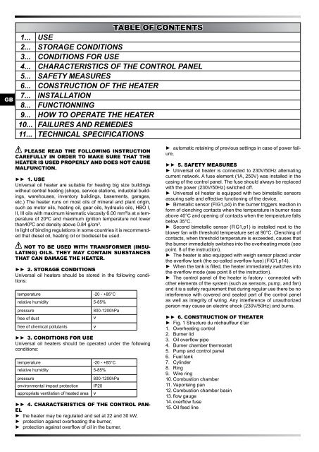
6. Construction of theater<br />
►►<br />
<strong>Fig</strong>. 1 Structure du réchauffeur d’air<br />
1. Overheating control<br />
2. Burner lid<br />
3. Oil overflow pipe<br />
4. Burner chamber thermostat<br />
5. Pump and control panel<br />
6. Fuel tank<br />
7. Cylinder<br />
8. Ring<br />
9. Wire ring<br />
10. Combustion chamber<br />
11. Vaporising pan<br />
12. Combustion chamber basin<br />
13. flow gauge<br />
14. overflow fuse<br />
15. Oil feed line