Standardized chemical pump in technical ceramic ... - Friatec
Standardized chemical pump in technical ceramic ... - Friatec
Standardized chemical pump in technical ceramic ... - Friatec

You also want an ePaper? Increase the reach of your titles
YUMPU automatically turns print PDFs into web optimized ePapers that Google loves.
Chemie-Norm<strong>pump</strong>e aus<br />
Technischer Keramik FRIKORUND ®<br />
<strong>Standardized</strong> Chemical Pump <strong>in</strong><br />
Technical Ceramic FRIKORUND ®<br />
Pompe Chimie Normalisée en<br />
Céramique Technique FRIKORUND ®<br />
Typ/Type FNC<br />
DIN 24256, ISO 2858, NFE 44-121, BS 5257<br />
RHEINHÜTTE<br />
P U M P E N
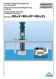
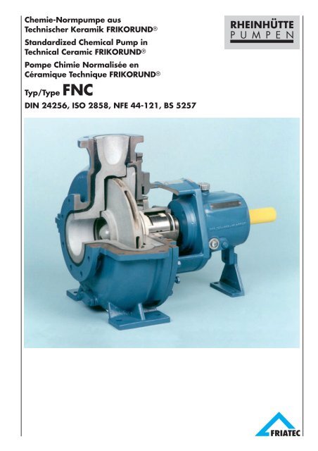
Chemie-Norm<strong>pump</strong>e aus technischer Keramik FRIKORUND ®<br />
<strong>Standardized</strong> <strong>chemical</strong> <strong>pump</strong> <strong>in</strong> <strong>technical</strong> <strong>ceramic</strong> FRIKORUND ®<br />
Pompe chimie normalisée en céramique technique FRIKORUND ®<br />
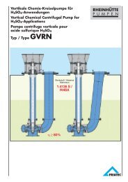
Die Chemie-Norm<strong>pump</strong>e Typ FNC ist<br />
e<strong>in</strong>e e<strong>in</strong>stufige, horizontale Kreisel<strong>pump</strong>e<br />
<strong>in</strong> Prozeßbauweise.<br />
Ausführungen, Abmessungen und<br />
Leistungen nach DIN 24256, ISO 2858;<br />
Übergrößen bis 250 / 400. Lochkreisdurchmesser<br />
der Flansche entsprechend<br />
unserem Maßblatt.<br />
Die Konstruktion dieser Pumpenreihe<br />
wurde entsprechend den Anforderungen<br />
der chemischen Industrie durchgeführt.<br />
Die Verschleißfestigkeit und universelle<br />
Chemikalienbeständigkeit der verwendeten<br />
Werkstoffe bietet große Vorteile für<br />
den E<strong>in</strong>satz <strong>in</strong> korrosiven und abrasiven<br />
Medien.<br />
Leistungsbereich<br />
Qmax = 1.500 m3/h; H max = 90 m<br />
Betriebstemperatur bis 120 °C<br />
Betriebsdruck bis 10 bar.<br />
Höhere Drücke auf Anfrage.<br />
Werkstoffe<br />
Pumpengehäuse und Gehäusedeckel<br />
aus technischer Keramik FRIKORUND® ,<br />
ge-panzert <strong>in</strong> GG oder GGG 40.3. Laufräder<br />
aus hochkorrosionsfesten Werkstoffen<br />
wie FRIKORUND® Titan, Tantal,<br />
Hastelloy u. a.<br />
Wellenabdichtungen<br />
Packungsstopfbuchse mit und ohne<br />
Sperrkammer. Verschiedene e<strong>in</strong>fachund<br />
doppeltwirkende Gleitr<strong>in</strong>gdichtungen.<br />
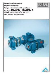
Das Schnittbild zeigt die Ausführung mit<br />
Stopfbuchsabdichtung. Der Gehäusedeckel<br />
ist mit universellem Anschliff versehen.<br />
Dieser ermöglicht den An- und<br />
Umbau auf die verschiedensten Wellenabdichtungen.<br />
Die Keramikteile s<strong>in</strong>d formschlüssig<br />
mit säurefestem Kitt <strong>in</strong> e<strong>in</strong>en<br />
Guß-Panzer e<strong>in</strong>gesetzt. Die Zentrierung<br />
des Gehäusedeckels im Gehäuse sowie<br />
die Aufnahme an dem Lagerträger erfolgt<br />
über die Panzerung. Saug- und Druckstutzen<br />
haben der Norm entsprechend<br />
unterschiedliche Nenn-weiten. Die Saugstutzen<br />
s<strong>in</strong>d, um die größtmögliche Saugfähigkeit,<br />
d.h. den kle<strong>in</strong>sten NPSH-Wert<br />
zu erzielen, größer als der Druckstutzen.<br />
The standardized <strong>chemical</strong> <strong>pump</strong> type<br />
FNC is a s<strong>in</strong>gle stage horizontal centrifugal<br />
process <strong>pump</strong>.<br />
Design, dimensions and performance is<br />
<strong>in</strong> accordance with DIN 24256, ISO<br />
2858; larger sizes up to 250 / 400.<br />
Flange pitch circle diameter accord<strong>in</strong>g to<br />
our dimension sheet.<br />
The design of this range of <strong>pump</strong>s has<br />
been based on the requirements of the<br />
<strong>chemical</strong> <strong>in</strong>dustry. The wear resistance<br />
and general <strong>chemical</strong> resistance of the<br />
materials used are of great advantage<br />
for the applications <strong>in</strong> corrosive and<br />
abrasive media.<br />
Range chart<br />
Qmax = 1500 m3/h H max = 90 m<br />
Operat<strong>in</strong>g temperature up uo 120 °C<br />
Operat<strong>in</strong>g pressure up to 10 bar.<br />
Higher pressures on request<br />
Materials<br />
Volute cas<strong>in</strong>g and cover made of <strong>technical</strong><br />
<strong>ceramic</strong> FRIKORUND®, protected by<br />
armour of cast iron GG or ductile cast<br />
iron GGG 40.3. Impellers made of the<br />
follow<strong>in</strong>g high corrosion-resistant<br />
materials: FRIKORUND®, Titanium,<br />
Tantalum, Hastelloy etc.<br />
Shaft seals<br />
Stuffed gland with or without lantern r<strong>in</strong>g;<br />
various s<strong>in</strong>gle and double act<strong>in</strong>g mechanical<br />
seals.<br />
The section draw<strong>in</strong>g below shows the<br />
construction of our standard <strong>chemical</strong><br />
<strong>pump</strong> with packed gland. The <strong>pump</strong><br />
cas<strong>in</strong>g cover is of standardized construction,<br />
designed to accept a variety of<br />
shaft seals.<br />
The <strong>pump</strong> l<strong>in</strong><strong>in</strong>gs made of high-strength<br />
corundum stoneware, are cemented to<br />
the cast outer armour. Centr<strong>in</strong>g of the<br />
<strong>pump</strong> cas<strong>in</strong>g cover to <strong>pump</strong> cas<strong>in</strong>g, and<br />
alignment of pedestals are arranged with<br />
reference to the outside armour.<br />
The adjacent sectional draw<strong>in</strong>gs of the<br />
various types of seal<strong>in</strong>g methods offer a<br />
choice for each application. Subsequent<br />
change to a different type of seal or<br />
material comb<strong>in</strong>ation is possible without<br />
chang<strong>in</strong>g the cas<strong>in</strong>g cover.<br />
La pompe chimie normalisée type FNC<br />
est une pompe centrifuge horizontale<br />
monocellulaire de construction process.<br />
Exécutions, dimensions et caractéristiques<br />
suivant DIN 24256, ISO 2858, et<br />
tailles supérieures jusqu’à 250 / 400. Les<br />
diamètres de perçage des brides sont<br />
<strong>in</strong>diqués sur notre plan d’encombrement.<br />
La construction de cette série de pompes<br />
a été réalisée à partir des exigences<br />
de l’<strong>in</strong>dustrie chimique. La très bonne<br />
tenue à l’abrasion et la résistance<br />
chimique universelle des matériaux<br />
utilisés offrent un énorme avantage pour<br />
l’utili-sation dans les produits corrosifs et<br />
abrasifs.<br />
Plage d’utilisation<br />
Qmax = 1500 m3/h H max = 90 m<br />
Température d’utilisation jusqu’à 120 °C.<br />
Pression d’utilisation jusqu’à 10 bar.<br />
En cas de pression plus élevées, veuillez<br />
nous consulter.<br />
Matériaux<br />
Corps de pompe et couvercle soit en<br />
céramique technique FRIKORUND®<br />
avec bl<strong>in</strong>dage en fonte grise ou en fonte<br />
à graphite sféroïdal FGS 400.3. Turb<strong>in</strong>es<br />
en matériaux à haute résistance à la<br />
corrosion: FRIKORUND®, titane, tantale,<br />
Hastelloy etc.<br />
Etanchéité d’arbre<br />
Presse-étoupe à tresses avec ou sans<br />
lanterne de blocage, diverses garnitures<br />
mécaniques simples ou doubles.<br />
Le plan-coupe représente l’exécution<br />
avec presse-étoupe. Le couvercle de<br />
corps de type universel permet de monter<br />
les types les plus variés d’étanchéité<br />
d’arbre. Les pièces en céramique sont<br />
<strong>in</strong>sérées dans un bl<strong>in</strong>dage en fonte à<br />
l’acide d’un ciment résistant aux acides.<br />
Le centrage du couvercle dans le corps<br />
de pompe, tout comme l’ajustement sur<br />
la chaise de palier, sont réalisés par<br />
l’<strong>in</strong>termédiaire du bl<strong>in</strong>dage.<br />
Conformément à la norme, les tubulures<br />
d’aspiration et de refoulement ont des<br />
diamètres différents. Af<strong>in</strong> d’obtenir les<br />
meilleurs capacités d’aspiration et donc<br />
les plus faibles valeurs de NPSH possibles,<br />
les tubulures d’aspiration sont<br />
plus grandes que celles de refoulement.<br />
2
Die Flanschanschlußmaße entsprechen<br />
jeweils der nächst größeren Nennweite<br />
der DIN 2501 PN 10. Der Druckstutzen<br />
ist radial nach oben, der Saugstutzen<br />
axial angeordnet. Die Aufstellung und<br />
Befestigung der Pumpe erfolgt über die<br />
an den Gehäusepanzern angegossenen<br />
Füßen. Auftretende Rohrleitungskräfte<br />
werden so direkt <strong>in</strong> die Grundplatte e<strong>in</strong>geleitet.<br />
In Kupplungsnähe erfolgt e<strong>in</strong>e<br />
Abstützung des Lagerträgers durch<br />
e<strong>in</strong>en Fuß.<br />
Suction and discharge nozzles have<br />
different diameters <strong>in</strong> accordance with<br />
the standard. In order to achieve the best<br />
possible suction properties, suction<br />
nozzles are generally larger than<br />
discharge nozzles. Dimensions for flange<br />
connections correspond to the next<br />
largest <strong>in</strong>ternal diameters of DIN 2501<br />
PN 10. Discharge nozzle is top fac<strong>in</strong>g<br />
and suction nozzle is side fac<strong>in</strong>g.<br />
Erection and anchor<strong>in</strong>g of the <strong>pump</strong> is<br />
done via the feet cast <strong>in</strong>tegrally with the<br />
body armour. Any possible pipe stresses<br />
are thus transferred directly to the baseplate.<br />
A foot located near the coupl<strong>in</strong>g<br />
supports the bear<strong>in</strong>g pedestal.<br />
Les dimensions de raccordement des<br />
brides corespondent à celles de la bride<br />
de taille immédiatement supérieure dans<br />
la norme DIN 2501 PN 10. La tubulure<br />
de refoulement est disposée radialement<br />
vers le haut, la tubulure d’aspiration est<br />
axiale. Le montage et la fixation de la<br />
pompe sont réalisés par l‘<strong>in</strong>termédiaire<br />
des pattes de fixation coulées avec le<br />
bl<strong>in</strong>dage. Les efforts éventuels<br />
provenant de la tuyauterie sont a<strong>in</strong>si<br />
directement transmis au socle. Côté<br />
accouplement, la chaise de palier est<br />
supportée par un béquille.<br />
Konstruktionsmekmale und Wellenabdichtungen<br />
Seite 4, 5.<br />
Design features and shaft seal<strong>in</strong>gs on<br />
page 4, 5.<br />
Caractéristiques et étanchéité d’arbre page 4, 5<br />
3
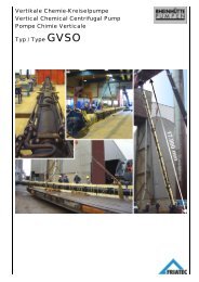
Schnittzeichnung und Teileverzeichnis<br />
Sectional Draw<strong>in</strong>g and Parts List<br />
Plan-coupe et désignations<br />
Typ / Type FNP<br />
Konstruktionsmerkmale<br />
● Laufrad <strong>in</strong> geschlossener Ausführung,<br />
fliegend gelagert<br />
● Welle läuft <strong>in</strong> ölgeschmierten Wälzlagern<br />
● Lager und Welle s<strong>in</strong>d zur Erzielung<br />
kle<strong>in</strong>ster Wellendurchbiegung groß dimensioniert<br />
● Dichtungsdurchmesser betragen<br />
43, 53, 65 und 90 mm<br />
● Axialschubausgleich durch Spaltr<strong>in</strong>gabdichtung<br />
und Entlastungsbohrungen<br />
am Laufrad<br />
● Bei Pumpen mit Laufrädern aus<br />
metallischen Werkstoffen kann die<br />
Motore<strong>in</strong>schaltung direkt erfolgen.<br />
Bei Keramik-Laufrädern ist Direkte<strong>in</strong>schaltung<br />
über elastische Kupplung bei<br />
Antriebsleistung bis 14 kW zulässig. Bei<br />
größeren Leistungen s<strong>in</strong>d Anlauf- oder<br />
Sicherheitskupplungen notwendig<br />
● Bei Ausfall von Laufrad oder Wellenabdichtung<br />
können diese, bei Verwendung<br />
e<strong>in</strong>er Ausbaukupplung, ohne<br />
Demontage der Rohrleitungen und des<br />
Antriebes ausgebaut werden.<br />
Pumpenteile aus unterschiedlichen<br />
Werkstoffen s<strong>in</strong>d komb<strong>in</strong>ierbar bzw.<br />
gegene<strong>in</strong>-ander austauschbar. Dadurch<br />
optimale Anpassungen an extreme<br />
Betriebsbed<strong>in</strong>gungen<br />
Wellenabdichtungen<br />
Bauform A für re<strong>in</strong>e und feststoffhaltige<br />
Medien.<br />
Das auswechselbare Stopfbuchsgehäuse<br />
ist mit zwei Anschlüssen für Zu- und<br />
Ablauf von Sperrflüssigkeit versehen.<br />
Etwaige Leckage wird durch e<strong>in</strong>e im<br />
Lagerträger angebrachte Topfwanne<br />
aufgefangen.<br />
Umstellung auf e<strong>in</strong> anderes Wellenabdichtungssystem<br />
jederzeit möglich.<br />
Bauform C 1 für re<strong>in</strong>e, bei Verwendung<br />
von SiC auch extrem abrasive, Fördermedien.<br />
Gleitr<strong>in</strong>gpaarung: Kohle / Kohle, Kohle /<br />
Oxidkeramik, SiC / SiC<br />
Design features<br />
● Impeller of closed design and freefloat<strong>in</strong>g<br />
● Shaft supported by oil-lubricated antifriction<br />
bear<strong>in</strong>gs<br />
● Robustly dimensioned shaft and bear<strong>in</strong>gs<br />
result <strong>in</strong> m<strong>in</strong>imal shaft deflection<br />
● Seal diameters are 43, 53, 65 and 90<br />
mm<br />
● Impeller relief holes and close<br />
clearances between impeller and cas<strong>in</strong>g,<br />
relieve axial thrust.<br />
● For <strong>pump</strong>s with metal impellers, direct<br />
start<strong>in</strong>g can be used. For <strong>ceramic</strong> impellers,<br />
direct start<strong>in</strong>g with a flexible coupl<strong>in</strong>g<br />
is possible for powers output up to<br />
14 kW. Above 14 kW, slow start<strong>in</strong>g<br />
should be used.<br />
● In the unlikely event of impeller or seal<br />
failure, these components can be replaced<br />
without dismantl<strong>in</strong>g pipework or<br />
drive, if a spacer type coupl<strong>in</strong>g is fitted<br />
Extreme operat<strong>in</strong>g conditions can be<br />
handled by us<strong>in</strong>g a comb<strong>in</strong>ation of different<br />
materials with<strong>in</strong> one <strong>pump</strong>. This<br />
allows optimum solutions for arduous<br />
<strong>pump</strong><strong>in</strong>g applications<br />
Shaft seal<strong>in</strong>g<br />
Design A for clean liquids and liquids<br />
conta<strong>in</strong><strong>in</strong>g solids.<br />
The <strong>in</strong>terchangeable gland is supplied<br />
with 2 connections for <strong>in</strong>let and outlet of<br />
seal<strong>in</strong>g liquid. Any leakage is collected <strong>in</strong><br />
a driptray located below the gland <strong>in</strong> the<br />
pedestal.<br />
A different shaft seal<strong>in</strong>g arrangement<br />
may be fitted at any time.<br />
Design C 1 for clean or extremely abrasive<br />
liquids, privided SiC (silicon carbide)<br />
is used.<br />
Seal r<strong>in</strong>g comb<strong>in</strong>ations: carbon / carbon,<br />
carbon / alum<strong>in</strong>a <strong>ceramic</strong>, SiC / SiC<br />
Caractéristiques constructives<br />
● Turb<strong>in</strong>e en exécution fermée, montage<br />
en porte-à-faux<br />
● Arbre supporté par des roulements<br />
lubrifiés à l’huile<br />
● Pour garantir une flexion m<strong>in</strong>imum de<br />
l’arbre les paliers et arbre sont largement<br />
dimensionnés<br />
● Diamètres de l’étanchéité d’arbre: 43,<br />
53, 65 et 90 mm<br />
● Equilibrage de la poussée axiales<br />
grâce à la bague d’étanchéité et aux<br />
trous de décharge dans la turb<strong>in</strong>e<br />
● Pour les pompes avec turb<strong>in</strong>es en<br />
métal, le démarage peut être fait en<br />
direct. Pour les turb<strong>in</strong>es en céramique,<br />
un démarrage en direct, avec accouplement<br />
élastique entre pompe et<br />
moteur, est possible jusqu’à en puissances<br />
d’entraînement de 14 kW. Pour les<br />
puissances supérieures, il faut prévoir un<br />
accouplement à démarrage progressif.<br />
● Si la pompe est équipée d’un accouplement<br />
à entretoise, il est possible<br />
d’échanger la turb<strong>in</strong>e ou l’étanchéitéd’-<br />
arbre sans avoir à démonter la tuyauterie<br />
ni le moteur. Les pièces de pompe<br />
peuvent être exécutées dans différents<br />
matériaux parfaitement <strong>in</strong>terchangeables.<br />
Cette comb<strong>in</strong>aison de plusieurs<br />
matériaux permet une adaptation<br />
optimale aux conditions de service<br />
extrêmes.<br />
Etanchéité d’arbre<br />
Exécution A pour liquides propres et<br />
chargés.<br />
Le boîtier de presse-étoupe <strong>in</strong>terchangeable<br />
est muni de deux raccords pour<br />
l’entrée et la sortie du liquide de blocage.<br />
Les éventuelles fuites sont recueillies par<br />
une cuvette de récupé-ration montée sur<br />
la chaise de palier.<br />
Il est à tout moment possible de monter<br />
un autre type d’étanchéité d’arbre.<br />
Exécuton C 1 pour liquides propres, ou<br />
même fortement chargés si l’on utilise le<br />
carbure de silicium (SiC).<br />
Comb<strong>in</strong>aison de gra<strong>in</strong>s: carbone /<br />
carbone, carbone / céramique, SiC / SiC<br />
4
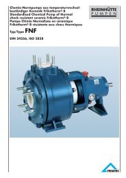
Wellenabdichtungen<br />
Shaft seal<strong>in</strong>g<br />
Etanchéité d’arbre<br />
Rotierender Gegenr<strong>in</strong>g, axialverschiebbarer<br />
Gleitr<strong>in</strong>g, produktbeaufschlagt.<br />
Federn und Druckr<strong>in</strong>g liegen außerhalb<br />
des Fördermediums. Das E<strong>in</strong>dr<strong>in</strong>gen von<br />
abrasiven Feststoffen <strong>in</strong> den Dichtspalt<br />
wird durch Zentrifugalkräfte beh<strong>in</strong>dert.<br />
Dieses Abdichtsystem kann auch auf<br />
Doppel- bzw. Tandemdichtung erweitert<br />
werden.<br />
Bauform CA für re<strong>in</strong>e und leicht verunre<strong>in</strong>igte<br />
Fördermedien.<br />
Gleitpaarung: Keramik / Kohle, Keramik /<br />
PTFE glas- oder kohlegefüllt.<br />
Außenliegende, e<strong>in</strong>fachwirkende Gleitr<strong>in</strong>gdichtung<br />
mit PTFE-Faltenbalg und<br />
korrosionsgeschützten Druckfedern.<br />
Stationärer Axialgleitr<strong>in</strong>g am Gehäusedeckel<br />
befestigt. Rotierende E<strong>in</strong>heit<br />
auf der Wellenschutzbuchse festgeklemmt.<br />
E<strong>in</strong>bau verschiedener Fabrikate<br />
möglich.<br />
Bauform C 2 für alle Fördermedien,<br />
Sperrmedium je nach E<strong>in</strong>satzfall, im<br />
Normalfall Wasser.<br />
Gleitpaarung: Keramik / Kohle, Keramik /<br />
PTFE glas- oder kohlegefüllt.<br />
Stationäre Keramikr<strong>in</strong>ge an Gehäusedeckel<br />
und Gleitr<strong>in</strong>ggehäuse. Rotierende<br />
E<strong>in</strong>heiten durch Mitnahme auf der<br />
Wellenschutzbuchse. Die E<strong>in</strong>stellung der<br />
Gleitr<strong>in</strong>gdichtung erfolgt bei der Montage.<br />
Auch hier ist der E<strong>in</strong>bau verschiedener<br />
Fabrikate möglich.<br />
Rotat<strong>in</strong>g counter r<strong>in</strong>g, axially movable<br />
stationary seat r<strong>in</strong>g, are product lubricated.<br />
Spr<strong>in</strong>gs and thrust r<strong>in</strong>g are not <strong>in</strong><br />
contact with the <strong>pump</strong>ed liquid. Abrasive<br />
solids are prevented from reach<strong>in</strong>g the<br />
seal faces by centrifugal force. This<br />
seal<strong>in</strong>g system can be extended to a<br />
double or tandem arrangement.<br />
Design CA for clean and slightly contam<strong>in</strong>ated<br />
liquids.<br />
Seal r<strong>in</strong>g comb<strong>in</strong>ation: <strong>ceramic</strong> / carbon,<br />
<strong>ceramic</strong> / glass or carbon filled PTFE.<br />
External s<strong>in</strong>gle act<strong>in</strong>g mechanical seal<br />
with PTFE bellows and corrosion<br />
resistant compression spr<strong>in</strong>g. Stationary<br />
seal face is fixed to cas<strong>in</strong>g cover.<br />
Rotat<strong>in</strong>g unit fixed to shaft sleeve.<br />
Various manufacturers’ seal types may<br />
be fitted.<br />
Design C 2 for all liquids. Seal<strong>in</strong>g liquid<br />
to be compatible with the <strong>pump</strong>ed liquid.<br />
Seal r<strong>in</strong>g comb<strong>in</strong>ation: <strong>ceramic</strong> / carbon,<br />
<strong>ceramic</strong> / glass or carbon filled PTFE.<br />
Stationary <strong>ceramic</strong> r<strong>in</strong>g fitted to cas<strong>in</strong>g<br />
cover and seal hous<strong>in</strong>g. Rotat<strong>in</strong>g unit on<br />
shaft sleeve. Adjustment of seal dur<strong>in</strong>g<br />
<strong>pump</strong> assembly.<br />
Various type of seal may be fitted<br />
Contre-gra<strong>in</strong> tournant et gra<strong>in</strong> coulissant<br />
axialement sont dans le liquide. Le<br />
ressort et la bague d’appui sont situés<br />
hors du liquide véhiculé. La force<br />
centrifuge empêche la pénétra-tion des<br />
particules abrasives dans la fente<br />
d’étanchéité. Ce système d’étan-chéité<br />
peut être adapté en garniture mécanique<br />
double ou tandem.<br />
Exécution CA pour liquides propres ou<br />
légèrement chargés.<br />
Comb<strong>in</strong>aison de gra<strong>in</strong>s: céramique /<br />
carbone, céramique / PTFE, chargé de<br />
verre ou carbone.<br />
Garniture mécanique simple extérieure<br />
avec soufflet en PTFE et ressorts<br />
protégés contre la corrosion. La gra<strong>in</strong><br />
stationnaire est montée sur le cou-vercle<br />
du corps. La partie mobile est fixée sur la<br />
chemise d’arbre. Il est possible de<br />
monter des garnitures de différentes<br />
marques.<br />
Exécution C 2 pour tous les liquides;<br />
déterm<strong>in</strong>ation du de blocage suivant le<br />
produit véhiculé, en cas normal, il s’agit<br />
de l’eau.<br />
Comb<strong>in</strong>aison de gra<strong>in</strong>s: céramique /<br />
carbone, céramique / PTFE, chargé de<br />
verre ou de carbone.<br />
Les gra<strong>in</strong>s stationnairers en céramique<br />
sont montés sur le couvercle du corps et<br />
le couvercle de garniture. Les deux<br />
parties mobiles sont fixées sur la chemise<br />
d’arbre Le réglage de la garniture se<br />
fait au montage. Dans ce cas aussi, il est<br />
possible de monter des garnitures de<br />
différentes marques.<br />
5
E<strong>in</strong>baumaße/Dimensions/Encombrement<br />
Pumpenmaße / Dimensions for <strong>pump</strong>s / Dimensions de pompes<br />
Größe<br />
Size<br />
Modéle<br />
Pumpenmaße<br />
Pump sizes<br />
Cotes de pompe<br />
Fußmaße<br />
Support dimensions<br />
Cotes de fixation<br />
für Schrauben<br />
for bolts<br />
pour boulons 1)<br />
Flansche / Flanges / Brides<br />
DIN 2501 PN 10 2)<br />
a f h 1 h 2 b m 1 m 2 n 1 n 2 n 3 s 1 s 2 w x d 1 l DN D DN S Dn D F g F k F l F b F z F<br />
32-160 80 385 132 160 50 100 70 240 190 110 M 12 M 12 285 100 24 50 32 50 32 150 88 110 18 18 4<br />
32-200 80 385 160 180 50 100 70 240 190 110 M 12 M 12 285 100 24 50 32 50 40 165 102 125 18 20 4<br />
40-250 100 500 180 225 65 125 95 320 250 110 M 12 M 12 370 140 32 80 40 65 50 185 122 145 18 20 4<br />
50-200 100 385 160 200 50 100 70 265 212 110 M 12 M 12 285 100 24 50 50 80 65 200 138 160 18 22 4<br />
50-320 125 500 225 280 65 125 95 345 280 110 M 12 M 12 370 140 32 80 50 80 80 220 158 180 18 22 8<br />
65-250 125 500 200 250 80 160 120 360 280 110 M 16 M 12 370 140 32 80 65 100 100 250 188 210 18 24 8<br />
65-320 125 530 225 280 80 160 120 400 315 110 M 16 M 12 370 140 42 110 65 100 125 285 212 240 23 24 8<br />
80-320 125 530 250 315 80 160 120 400 315 110 M 16 M 12 370 140 42 110 80 125 150 340 268 295 23 26 8<br />
100-400 140 530 280 355 100 200 150 500 400 110 M 20 M 12 370 160 42 110 100 125 250 445 370 400 23 28 12<br />
125-400 140 530 315 400 100 200 150 500 400 110 M 20 M 12 370 160 42 110 125 150 300 505 430 460 23 30 16<br />
250-400 240 670 450 550 125 250 190 710 585 140 M 20 M 16 500 250 55 110 250 300<br />
1) Wellenende / Shaft end / Bout d’arbre: DIN 748, Nut und Paßfeder / Keyway and key / Ra<strong>in</strong>ure et clavette: DIN 6885 (Blatt 1 / pag.1 )<br />
2) Flansche nach DIN 2501, PN 10, jedoch e<strong>in</strong>e Nennweite größer. Verb<strong>in</strong>dliche Abmessungen siehe E<strong>in</strong>zelmaßblätter<br />
2) Flange connections are to DIN 2501, PN 10, but one . size larger. For fix<strong>in</strong>g dimensions see <strong>in</strong>dividual dimension sheets<br />
2) Raccordement des brides suivant DIN 2501, PN 10, mais avec le diamètre supérieur. Dimensions contractuelles sur feuillets séparés.<br />
Grundplattenmaße / Dimensions for baseplates / Dimensions de plaques de fondation<br />
Größe<br />
Size<br />
Modéle<br />
L B a 1 3) a 2<br />
3)<br />
Nr. 2 820 360 340 400 450 19 65 40 800 540 130 4 CM 20 x 200 Mu<br />
Nr. 4 1020 450 430 490 540 24 80 50 1000 660 170 4 CM 20 x 200 Mu<br />
Nr. 6 1270 500 480 550 610 24 100 50 1250 840 205 4 CM 24 x 320 Mu<br />
Nr. 7 1420 550 530 600 660 28 100 65 1400 940 230 4 CM 24 x 320 Mu<br />
Nr. 8 1620 620 600 670 730 28 100 65 1600 1060 270 4 CM 24 x 320 Mu<br />
Nr. 9 1820 620 600 670 730 28 100 65 1800 1200 300 4 CM 24 x 320 Mu<br />
Nr. 12 2220 880 860 950 1010 28 150 85 2200 1600 800 300 6 CM 24 x 320 Mu<br />
Nr. 13 2520 880 860 950 1010 28 150 85 2500 1900 950 300 6 CM 20 x 320 Mu<br />
Ste<strong>in</strong>schrauben<br />
b 1 b 2 b 3 d h h 1 l 1 l 2 l 3 l 6 z 3) Die Maße a 1 und a 2 richten sich<br />
3<br />
Anchor bolts nach der jeweiligen Pumpengröße.<br />
Boulons de scellemDie Grundplattengröße wird entsprechend<br />
Pumpe und Motorgröße<br />
ausgewählt /<br />
3) The dimensions<br />
a 1 and a 2 depend on the <strong>pump</strong><br />
size. The size of the baseplates wil<br />
be determ<strong>in</strong>ed accord<strong>in</strong>g to <strong>pump</strong><br />
and motor dimensions /<br />
3) Les<br />
dimen-sions a 1 et a 2 se conformen<br />
au type de pompes. La dimension<br />
de la plaque de fondation est<br />
déter-m<strong>in</strong>ée conformement aux<br />
dimensions de la pompe et du<br />
moteur.<br />
Die Dichtleiste der Rohrleitung oder des Kompensators muß den Maßen DN und gF entsprechen und absolut plan<br />
se<strong>in</strong>. Der Anschluß entspricht DIN 2501 PN 10, jedoch jeweils e<strong>in</strong>e Nennweite größer als die Pumpennennweite. Bei<br />
abweichenden Rohrleitungs-Nennweiten konisches Zwischenstück verwenden.<br />
The seal<strong>in</strong>g gaskets of the pipework or compensators must correspond to the dimensions DN and gF and must be<br />
absolutely flat. The connections correspond to DIN 2501 PN 10 but are allways one size larger than the <strong>pump</strong> size.<br />
If this is not the case, then a conical <strong>in</strong>termediate piece should be used.<br />
6<br />
La portée de jo<strong>in</strong>t de la tuyauterie ou du compensateur doit correspondre aux cotes DN et gF, et doit être<br />
absolument plane. La raccordement correspond à la norme DIN 2501 PN 10, mais avec le diamètre immédiatement<br />
supérieur à celui de la pompe. Si les dimensions de la tuyauterie sont différentes, pr´voir alors des pièces de<br />
raccordement coniques.
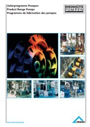
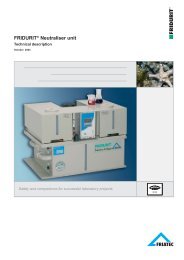
Leistungsübersicht<br />
Range chart<br />
Plage d’utilisation<br />
n = 1450 m<strong>in</strong> -1 , n = 2900 m<strong>in</strong> -1 7<br />
Förderhöhe H / Differential head H / Hauteur manométrique H (m)<br />
Förderhöhe H / Differential head H / Hauteur manométrique H (ft)<br />
Förderstrom Q / Quantity Q / Débit Q /m3/h<br />
Die Zugehörigkeit der e<strong>in</strong>zelnen Typen<br />
zum jeweiligen Lagerträger ist im Leistungsfeld<br />
mit unterschiedlichen Farben<br />
gekennzeichnet.<br />
Zugehörigkeit zum Lagerträger bedeutet:<br />
Gleiche Lagerung, Welle, Wellenbuchse<br />
und Wellenabdichtung.<br />
The different bear<strong>in</strong>g bracket sizes are<br />
represented on the performance diagram<br />
by different colour.<br />
For each size of bear<strong>in</strong>g bracket the follow<strong>in</strong>g<br />
parts are identical: bear<strong>in</strong>gs,<br />
shaft, shaft sleeve and shaft seal.<br />
L’attribution des divers types au paliersupport<br />
particulier est marquée dans le<br />
diagramme de puissance par le coloration.<br />
L’attribution au palier-support repré-sente:<br />
Exécution identique de paliers, arbre<br />
douille d’arbre et étanchéité d’arbre.
3.63.0001 – 0304, d-e-f<br />
FRIATEC-Rhe<strong>in</strong>hütte GmbH & Co. KG<br />
Postfach / P.O.B. 12 05 45 • D-65083 Wiesbaden<br />
Rhe<strong>in</strong>gaustr. 96 -98 • D-65203 Wiesbaden<br />
Tel. +49 (0)611/604-0 • Fax +49 (0)611/604-328<br />
Internet: www.friatec.de • www.rhe<strong>in</strong>huette.de<br />
e-mail: <strong>in</strong>fo@rhe<strong>in</strong>huette.de • service@rhe<strong>in</strong>huette.de<br />
III.04 WST