Manual de usuario - Soler & Palau
Manual de usuario - Soler & Palau
Manual de usuario - Soler & Palau

You also want an ePaper? Increase the reach of your titles
YUMPU automatically turns print PDFs into web optimized ePapers that Google loves.
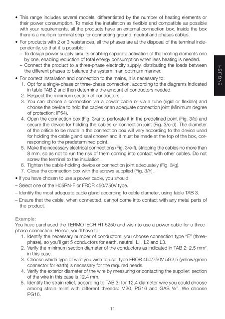
• This range inclu<strong>de</strong>s several mo<strong>de</strong>ls, differentiated by the number of heating elements or<br />
their power consumption. To make the installation as flexible and compatible as possible<br />
with your requirements, all the products have an external connection box. Insi<strong>de</strong> the box<br />
there is a multipin terminal strip for connecting ground, neutral and phases cables.<br />
• For products with 2 or 3 resistances, all the phases are at the disposal of the terminal in<strong>de</strong>pen<strong>de</strong>ntly,<br />
so that it is possible:<br />
– To <strong>de</strong>sign power supply circuits enabling separate activation of the heating elements one<br />
by one, enabling reduction of total energy consumption when less heating is nee<strong>de</strong>d.<br />
– Connect the product to a three-phase electricity supply, distributing the loads between<br />
the different phases to balance the system in an optimum manner.<br />
• For correct installation and connection to the mains, it is necessary to:<br />
1. Opt for a single-phase or three-phase connection, according to the diagrams indicated<br />
in table TAB 2 and then <strong>de</strong>termine the amount of conductors nee<strong>de</strong>d.<br />
2. Respect the minimum section of conductors.<br />
3. You can choose a connection via a power cable or via a tube (rigid or flexible) and<br />
choose the <strong>de</strong>vice to hold the cables or an a<strong>de</strong>quate connection joint (Minimum <strong>de</strong>gree<br />
of protection: IP54).<br />
4. Open the connection box (Fig. 3/a) to perforate it in the pre<strong>de</strong>fined point (Fig. 3/b) and<br />
secure the <strong>de</strong>vice for holding the cables or connection joint (Fig. 3/c-d). The diameter<br />
of the orifice to be ma<strong>de</strong> in the connection box will vary according to the <strong>de</strong>vice used<br />
for holding the cable gland seal chosen and it must be ma<strong>de</strong> at the top of the box, corresponding<br />
to the pre<strong>de</strong>termined point.<br />
5. Make the necessary electrical connections (Fig. 3/e-f), stripping the cables no more than<br />
8 mm, so as not to run the risk of them coming into contact with other cables. Do not<br />
screw the terminal to the insulation.<br />
6. Tighten the cable-holding <strong>de</strong>vice or connection joint a<strong>de</strong>quately (Fig. 3/g).<br />
7. Close the connection box with the screws supplied (Fig. 3/h).<br />
• If you have chosen to use a power cable, you should:<br />
– Select one of the H05RN-F or FROR 450/750V type.<br />
– I<strong>de</strong>ntify the most a<strong>de</strong>quate cable gland according to cable diameter, using table TAB 3.<br />
– Ensure that the cable, when connected, cannot come into contact with any metal parts of<br />
the product.<br />
ENGLISH<br />
Example:<br />
You have purchased the TERMOTECH HT-5250 and wish to use a power cable for a threephase<br />
connection. Hence, you’ll have to:<br />
1. I<strong>de</strong>ntify the necessary number of conductors: you choose connection type “E” (threephase),<br />
so you’ll get 5 conductors for earth, neutral, L1, L2 and L3.<br />
2. Verify the minimum section diameter of the conductors as indicated in TAB 2: 2,5 mm 2<br />
in this case.<br />
3. Choose which type of wire you wish to use: type FROR 450/750V 5G2,5 (yellow/green<br />
connector for earth) is necessary for the required needs.<br />
4. Verify the exterior diameter of the wire by measuring or contacting the supplier: section<br />
of the wire in this case is 12,4 mm.<br />
5. I<strong>de</strong>ntify the strain relief, according to TAB 3: for 12,4 diameter wire you could choose<br />
among strain relief with different threads: M20, PG16 and GAS ⅝”. We choose<br />
PG16.<br />
11