Istruzioni d'uso - Refco Manufacturing Ltd.
Istruzioni d'uso - Refco Manufacturing Ltd.
Istruzioni d'uso - Refco Manufacturing Ltd.

You also want an ePaper? Increase the reach of your titles
YUMPU automatically turns print PDFs into web optimized ePapers that Google loves.
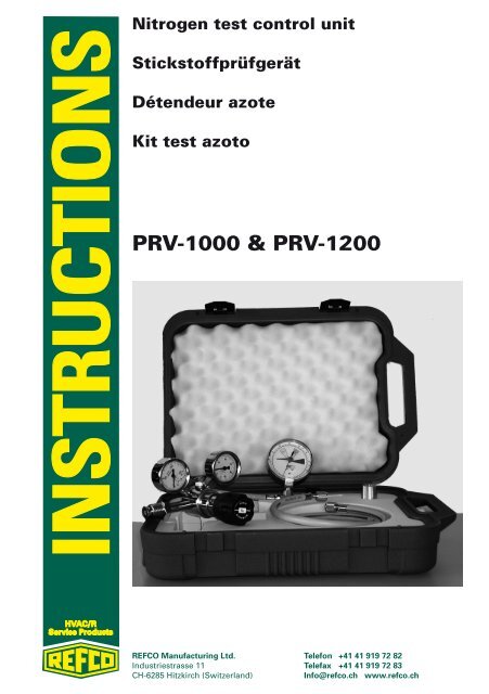
Nitrogen test control unit<br />
Stickstoffprüfgerät<br />
Détendeur azote<br />
Kit test azoto<br />
PRV-1000 & PRV-1200<br />
HVAC/R<br />
Service Products<br />
REFCO <strong>Manufacturing</strong> <strong>Ltd</strong>. Telefon +41 41 919 72 82<br />
Industriestrasse 11 Telefax +41 41 919 72 83<br />
CH-6285 Hitzkirch (Switzerland)<br />
Info@refco.ch www.refco.ch
Index of contents<br />
Index of contents 2<br />
Introduction 3<br />
Application range 3<br />
Available versions 3<br />
Technical data 3<br />
Drawings 4<br />
Component part drawing 4<br />
System drawing 4<br />
Pressure regulator 5<br />
Correct use 5<br />
Not correct use 5<br />
Pressure regulation 5<br />
Connection of pressure regulator 5<br />
Disconnecting the pressure regulator 6<br />
Pressure- and tightness tests 6<br />
Washing and blow-out 7<br />
Maintenance 8<br />
Repairs 8<br />
Caution 8<br />
HVAC/R<br />
Service Products<br />
REFCO <strong>Manufacturing</strong> <strong>Ltd</strong>. Telefon +41 41 919 72 82<br />
Industriestrasse 11 Telefax +41 41 919 72 83<br />
CH-6285 Hitzkirch (Switzerland)<br />
Info@refco.ch www.refco.ch<br />
2
Introduction<br />
Application range<br />
• Pressure- and tightness tests for medium and larger<br />
refrigeration cycles<br />
• Washing and blow-out of refrigeration cycles<br />
• Simple and safe pressure regulation<br />
Available versions<br />
PRV-1000 For nitrogen bottle connection according to UNI 4409<br />
PRV-1200 For nitrogen bottle connection according to DIN 477<br />
Technical data<br />
• Connection PRV 1000<br />
• Connection PRV 1200<br />
• Pressure regulator<br />
• Pressure control valve<br />
• Marking gauge<br />
• Charging hose<br />
• Adapter for PRV-1000<br />
• Adapter piece 1/4SAE<br />
hex nut male for nitrogen bottle norm<br />
UNI 4409 (W 21.7 x 1/14“ anti-clockwise)<br />
coupling nut female for nitrogen bottle,<br />
DIN 477 no. 13 (W 24.32 x 1/14“<br />
anti-clockwise)<br />
max. 220 bar primary<br />
5 - 50 bar secondary<br />
adjusted for 55 bar, secured<br />
80 mm, including marking indicator<br />
900 mm with 1/4“ connector,<br />
certified according to SAE J2196<br />
threads FM UNI 4409 to M10 x 1 FM<br />
for little nitrogen bottles<br />
adapter piece with vale deadener,<br />
¼” SAE x ½”-20UNF<br />
HVAC/R<br />
Service Products<br />
REFCO <strong>Manufacturing</strong> <strong>Ltd</strong>. Telefon +41 41 919 72 82<br />
Industriestrasse 11 Telefax +41 41 919 72 83<br />
CH-6285 Hitzkirch (Switzerland)<br />
Info@refco.ch www.refco.ch<br />
3
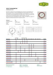
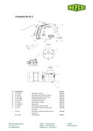
Drawings<br />
Component part drawing<br />
1.) Connection PRV 1000/1200 4.) Marking gauge with ball valve<br />
2.) Pressure regulator 5.) Charging hose<br />
3.) Pressure control valve 6.) Adapter to M10x1 thread<br />
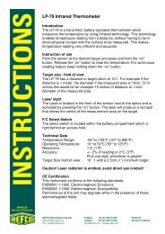
System drawing<br />
N2<br />
HVAC<br />
HVAC/R<br />
Service Products<br />
1.) Connection PRV 1000/1200 9.) Primary gauge<br />
2.) Pressure regulator 10.) Secondary gauge<br />
3.) Pressure control valve 11.) Connector for charging hose<br />
4.) Marking gauge 12.) Plug for marking gauge<br />
5.) Charging hose 13.) Connection for refrigeration<br />
7.) Gas cylinder system<br />
8.) Hand wheel 14.) Refrigeration system<br />
REFCO <strong>Manufacturing</strong> <strong>Ltd</strong>. Telefon +41 41 919 72 82<br />
Industriestrasse 11 Telefax +41 41 919 72 83<br />
CH-6285 Hitzkirch (Switzerland)<br />
Info@refco.ch www.refco.ch<br />
4
Pressure regulator<br />
Correct use<br />
The pressure regulator has been developed especially for pressure regulation<br />
of nitrogen (N2). The required pressure range can be positioned and kept<br />
constant easily. The maximum primary pres-sure is 220 bar. The secondary<br />
pressure is 5-50 bar. The safety valve (pressure control valve) is positioned<br />
to 55 bar and sealed with red lacquer. Manipulations on the pressure control<br />
valve are strictly forbidden. The pressure regulator may be used only for<br />
nitrogen pressure cylinders.<br />
Not correct use<br />
• The pressure regulator may not be used with liquid nitrogen.<br />
• The ambient air temperature may not be below -20°C and not higher<br />
than 60°C.<br />
• The pressure regulator is in conformity with the EU Directive 2002/95/EC<br />
(RoHS Directive).<br />
• Any manipulation or modification on the pressure regulator is not<br />
allowed.<br />
• A non correct handling may lead to severe accidents and damages of<br />
persons and/or Installations.<br />
Pressure regulation<br />
Connection of pressure regulator<br />
• During the installation of the pressure regulator, all components which<br />
may be in contact with the gas have to be totally free of oil and grease.<br />
• Before connecting the pressure regulator to the gas bottle, make sure<br />
that the content is absolutely nitrogen (N2).<br />
• Check the connection of the nitrogen cylinder. Is it damaged or leaky, do<br />
never connect the pressure regulator.<br />
• Release the pressure regulator by turning the positioning hand wheel to<br />
the null-position (anti-clockwise)<br />
• Put the attached teflon gasket in the connecting hex-nut.<br />
• Connect the pressure regulator to the nitrogen cylinder by putting on<br />
well the connecting hex-nut. To avoid damaging the gasket, do not fasten<br />
too strong the connecting hex-nut.<br />
• Now open slowly the gas bottle valve. The primary gauge indicates now<br />
the cylinder pressure.<br />
• By turning the hand wheel (clockwise) you can position the requested<br />
pressure and read it off on the secondary gauge.<br />
HVAC/R<br />
Service Products<br />
REFCO <strong>Manufacturing</strong> <strong>Ltd</strong>. Telefon +41 41 919 72 82<br />
Industriestrasse 11 Telefax +41 41 919 72 83<br />
CH-6285 Hitzkirch (Switzerland)<br />
Info@refco.ch www.refco.ch<br />
5
Disconnecting the pressure regulator<br />
• The pressure regulator may never be dismantled under pressure!<br />
• Close the nitrogen cylinder valve.<br />
• Release the pressure from the low pressure range. Persuade yourself<br />
that the pressure regulator and the nitrogen cylinder connector are not<br />
under pressure at all. By checking it the primary pressure and the<br />
secondary pressure gauge have to show zero.<br />
• First hold the pressure regulator by hand and ease with care (residual<br />
pressure may still be existing) the connector between the pressure<br />
regulator and the gas cylinder valve with a half or full rotation. To be sure<br />
that the gas is escaped, dangle slightly with the pressure regulator. Not<br />
till then disconnect the pressure regulator.<br />
• Make sure the positioning hand wheel is totally released (turned<br />
anti-clockwise) and store the pressure regulator together with the other<br />
components in the case. The Threaded connection and gauges are now<br />
protected from damages.<br />
Pressure- and tightness tests<br />
• Connect the pressure regulator (see subject “pressure regulation”)<br />
• Now connect the charging hose to the connector of the pressure<br />
regulator.<br />
• Connect the other end of the charging hose (45° bended) to the marking<br />
gauge (Connector with plug valve)<br />
• Make sure the plug valve is closed. The yellow handhold is in your<br />
direction.<br />
• Tighten the connector to the refrigeration cycle.<br />
• Now open slowly the gas cylinder valve. The primary gauge indicates<br />
now the gas cylinder pressure.<br />
• Open now the yellow plug valve of the marking gauge. The plug valve<br />
shows now in direction to the hose.<br />
• By turning the hand wheel (clockwise) you can adjust the requested<br />
pressure. The testing pressure is depending on the refrigerant using in<br />
the refrigeration cycle. See chart:<br />
Refrigerant and the testing range<br />
Refrigerant<br />
R134A<br />
R404A<br />
R407C<br />
R507<br />
R22<br />
R410A<br />
Pressure<br />
18-22 bar<br />
28-32 bar<br />
28-32 bar<br />
28-32 bar<br />
28-32 bar<br />
38-42 bar<br />
HVAC/R<br />
Service Products<br />
REFCO <strong>Manufacturing</strong> <strong>Ltd</strong>. Telefon +41 41 919 72 82<br />
Industriestrasse 11 Telefax +41 41 919 72 83<br />
CH-6285 Hitzkirch (Switzerland)<br />
Info@refco.ch www.refco.ch<br />
6
• Once you have positioned the correct pressure rang, mark the pressure<br />
indicator of the gauge. Move for this purpose the red indicator exactly<br />
above the pressure regulator of the gauge.<br />
• Wait for approx. 20 seconds. Are the marking indicator and the gauge<br />
indicator still on top of each other you can now close the yellow handhold<br />
and remove the charging hose.<br />
• The marking gauge is now connected to the refrigeration cycle with the<br />
desired pressure.<br />
• The testing time depends on the size and nature of the refrigeration<br />
cycle. Is after the testing time the marking indicator and the gauge<br />
indicator still congruent indicate that the refrigeration cycle is tight. Is the<br />
pressure indicator and the marking indicator decreased, the refrigeration<br />
cycle is not tight.<br />
Washing and blow-out<br />
• Put an adequate bucket under the output connection of the refrigeration<br />
system and open it now.<br />
• Connect the pressure regulator (see subject “pressure regulation”)<br />
• Connect the charging hose to the connector of the pressure regulator.<br />
• Connect the other end of the charging hose (45° bended) to the marking<br />
gauge (Connector with plug valve)<br />
• Make sure the plug valve is closed. The yellow handhold is in your<br />
direction.<br />
• Tighten the connector to the refrigeration cycle.<br />
• Now open slowly the gas cylinder valve. The primary gauge indicates<br />
now the gas cylinder pressure.<br />
• Open now the yellow plug valve of the marking gauge. The plug valve<br />
shows now in direction to the hose.<br />
• By turning the hand wheel (clockwise) you can adjust the requested<br />
pressure. For washing adjust a pressure between 4 and 7 bar.<br />
• The system is now blew-out by a steady pressure.<br />
HVAC/R<br />
Service Products<br />
REFCO <strong>Manufacturing</strong> <strong>Ltd</strong>. Telefon +41 41 919 72 82<br />
Industriestrasse 11 Telefax +41 41 919 72 83<br />
CH-6285 Hitzkirch (Switzerland)<br />
Info@refco.ch www.refco.ch<br />
7
Maintenance<br />
• REFCO <strong>Manufacturing</strong> <strong>Ltd</strong>. advises to maintain the pressure regulator<br />
periodically.<br />
• The maintenance has to be carried out only by experienced and skilled<br />
specialists.<br />
• Keep gasket, seals and gauges in perfect conditions.<br />
• Use only original spare parts. The repair kit is available by REFCO<br />
<strong>Manufacturing</strong> <strong>Ltd</strong>.<br />
Repairs<br />
• Repairs have to be carried out only from skilled specialist or REFCO<br />
<strong>Manufacturing</strong> <strong>Ltd</strong>.<br />
• REFCO <strong>Manufacturing</strong> <strong>Ltd</strong>. is not liable for repairs or modifications which<br />
have been carried out by the user or other persons who do not have the<br />
permission of REFCO <strong>Manufacturing</strong> <strong>Ltd</strong>.<br />
Caution<br />
The safety valve (pressure control valve) is positioned to 55 bar<br />
and sealed with red lacquer. Any manipulations on the pressure<br />
control valve are strictly forbidden.<br />
The use of this set is only for testing refrigeration systems under<br />
use of nitrogen.<br />
The set may be used only by skilled HVAC/R specialists.<br />
The test unit is very sensitive. After incorrect use or impact effects<br />
it has to be rechecked through a specialist department.<br />
HVAC/R<br />
Service Products<br />
REFCO <strong>Manufacturing</strong> <strong>Ltd</strong>. Telefon +41 41 919 72 82<br />
Industriestrasse 11 Telefax +41 41 919 72 83<br />
CH-6285 Hitzkirch (Switzerland)<br />
Info@refco.ch www.refco.ch<br />
8
Inhaltsverzeichnis<br />
Inhaltsverzeichnis 9<br />
Einleitung 10<br />
Anwendungsbereich 10<br />
Erhältliche Ausführungen 10<br />
Technische Daten 10<br />
Zeichnungen 11<br />
Einzelteil Zeichnung 11<br />
System Zeichnung 11<br />
Druckminderer 12<br />
Sachgemässe Benützung 12<br />
Nicht sachgemässe Benützung 12<br />
Druckregulierung 12<br />
Anschluss des Druckminderers 12<br />
Entfernen des Druckminderers 13<br />
Druck- und Dichtheitsprüfungen 13<br />
Spülen und ausblasen 14<br />
Wartung 15<br />
Reparaturen 15<br />
Warnung 15<br />
HVAC/R<br />
Service Products<br />
REFCO <strong>Manufacturing</strong> <strong>Ltd</strong>. Telefon +41 41 919 72 82<br />
Industriestrasse 11 Telefax +41 41 919 72 83<br />
CH-6285 Hitzkirch (Switzerland)<br />
Info@refco.ch www.refco.ch<br />
9
Einleitung<br />
Anwendungsbereich<br />
• Druck- und Dichtheitsprüfungen bei mittleren und grösseren Kältekreisläufen<br />
• Spülen und ausblasen von Kältekreisläufen<br />
• Einfache und sichere Druckregulierung<br />
Erhältliche Ausführungen<br />
PRV-1000 Für Stickstoffflaschenanschluss nach UNI 4409<br />
PRV-1200 Für Stickstoffflaschenanschluss nach DIN 477<br />
Technische Daten<br />
• Anschluss PRV 1000 Mutter, männlich, für Stickstoffflaschen Norm<br />
UNI 4409 (W 21.7 x 1/14“ gegen<br />
Urzeigerrichtung drehend)<br />
• Anschluss PRV 1200 Überwurfmutter, weiblich, für Stickstoffflaschen,<br />
DIN 477 (W 24.32 x 1/14“ gegen Urzeigerrichtung<br />
drehend)<br />
• Druckminderer max. 220 bar primär<br />
5-50 bar sekundär<br />
• Überdruckventil: Eingestellt auf 55 bar und gesichert<br />
• Markiermanometer Ø 80 mm, mit Markierzeiger<br />
• Füllschlauch 900 mm mit ¼“ Anschluss, geprüft gemäss<br />
SAE J2196<br />
• Adapter für PRV-1000 Gewinde FM UNI 4409 zu M10 x 1 für kleine<br />
Stickstoffflaschen<br />
• Übergangsstück 1/4SAE Übergangsstück mit Ventildrücker,<br />
¼“ SAE x ½“ -20UNF<br />
HVAC/R<br />
Service Products<br />
REFCO <strong>Manufacturing</strong> <strong>Ltd</strong>. Telefon +41 41 919 72 82<br />
Industriestrasse 11 Telefax +41 41 919 72 83<br />
CH-6285 Hitzkirch (Switzerland)<br />
Info@refco.ch www.refco.ch<br />
10
Zeichnungen<br />
Einzelteil Zeichnung<br />
1.) Anschluss PRV 1000/1200 4.) Markiermanometer mit<br />
2.) Druckminderer Kugelhahn<br />
3.) Überdruckventil 5.) Füllschlauch<br />
6.) Adapter zu M10x1 Gewinde<br />
System Zeichnung<br />
N2<br />
HVAC<br />
1.) Anschluss PRV 1000/1200 8.) Handrad<br />
2.) Druckminderer 9.) Primär - Manometer<br />
3.) Überdruckventil 10.) Sekundär - Manometer<br />
4.) Markiermanometer 11.) Anschluss für Füllschlauch<br />
5.) Füllschlauch 12.) Hahn zu Markier-Manometer<br />
7.) Gasflasche 13.) Anschluss zu Kältesystem<br />
14.) Kältesystem<br />
HVAC/R<br />
Service Products<br />
REFCO <strong>Manufacturing</strong> <strong>Ltd</strong>. Telefon +41 41 919 72 82<br />
Industriestrasse 11 Telefax +41 41 919 72 83<br />
CH-6285 Hitzkirch (Switzerland)<br />
Info@refco.ch www.refco.ch<br />
11
Druckminderer<br />
Sachgemässe Benützung<br />
Der Druckminderer ist speziell zur Druckregulierung von Stickstoff (N2) entwickelt<br />
worden. Der gewünschte Druckbereich kann problemlos eingestellt<br />
und konstant gehalten werden. Der maximale primäre Druck beträgt 220<br />
bar. Der sekundäre Druck beträgt 5-50 bar. Das Sicherheitsventil (Überdruckventil)<br />
ist auf 55 bar eingestellt und mit rotem Lack versiegelt. Manipulationen<br />
am Sicherheitsventil sind verboten. Der Druckminderer darf nur<br />
für Stickstoffdruckflaschen verwendet werden.<br />
Nicht sachgemässe Benützung<br />
• Der Druckminderer darf nicht bei flüssigem Stickstoff verwendet<br />
werden.<br />
• Die Umgebungstemperatur darf nicht tiefer als -20°C und nicht höher als<br />
60°C betragen.<br />
• Der Druckminderer ist konform mit der EU-Richtlinie 2002/95/EC (RoHS<br />
Directive).<br />
• Am Druckminderer darf nichts verändert oder manipuliert werden.<br />
• Eine nicht korrekte Handhabung kann zu schweren Unfällen und Beschädigung<br />
von Personen und/oder Anlagen führen.<br />
Druckregulierung<br />
Anschluss des Druckminderers<br />
HVAC/R<br />
Service Products<br />
• Während der Montage des Druckminderers müssen alle Komponenten,<br />
welche in Kontakt mit dem Gas kommen könnten, komplett frei von Ölen<br />
und Fetten sein.<br />
• Bevor Sie den Druckminderer an die Gasflasche anschliessen, überprüfen<br />
Sie, ob es sich dabei auch wirklich um Stickstoff (N2) handelt.<br />
• Überprüfen Sie den Anschluss der Stickstoffflasche. Ist er beschädigt<br />
oder undicht, schliessen Sie den Druckminderer unter keinen Umständen<br />
an.<br />
• Entlasten Sie den Druckminderer durch die Drehung des Einstell-Handrades<br />
auf die Null-Position (entgegen der Uhrzeigerrichtung).<br />
• Legen Sie die beigelegte Teflondichtung in die Anschlussmutter.<br />
• Schliessen Sie den Druckminderer an die Stickstoffflasche an, indem Sie<br />
die Anschlussmutter gut anziehen. Befestigen Sie den Gewindeanschluss<br />
nicht zu stark, es könnte so die Dichtung beschädigt werden.<br />
• Jetzt öffnen Sie langsam das Gasflaschenventil. Das Primär-Manometer<br />
zeigt Ihnen nun den Flaschendruck an.<br />
• Durch drehen des Handrades (in Uhrzeigerrichtung) können Sie nun den<br />
gewünschten Druck einstellen und dieser beim Sekundär-Manometer<br />
ablesen.<br />
REFCO <strong>Manufacturing</strong> <strong>Ltd</strong>. Telefon +41 41 919 72 82<br />
Industriestrasse 11 Telefax +41 41 919 72 83<br />
CH-6285 Hitzkirch (Switzerland)<br />
Info@refco.ch www.refco.ch<br />
12
Entfernen des Druckminderers<br />
• Der Druckminderer darf nicht unter Druck stehend abmontiert werden!<br />
• Schliessen Sie das Stickstoffflaschenventil.<br />
• Lassen Sie den Druck aus dem Niederdruckbereich ab. Überzeugen Sie<br />
sich, dass der Druckminderer und der Stickstoffflaschenanschluss überhaupt<br />
nicht unter Druck stehen. Bei der Überprüfung muss der Vordruckund<br />
Hinterdruckmanometer die Null anzeigen.<br />
• Zuerst mit der Hand den Druckminderer festhalten und mit Vorsicht<br />
(es könnte noch Restdruck vorhanden sein) den Anschluss zwischen<br />
dem Druckminderer und dem Gasflaschenventil mit einer halben oder<br />
einer ganzen Drehung lockern. Um sicher zu gehen, dass das Gas ganz<br />
ausgeströmt ist, wackeln Sie kurz mit dem Druckminderer. Erst dann entfernen<br />
Sie den Druckminderer.<br />
• Vergewissern Sie sich, dass das Einstellhandrad vollkommen entspannt<br />
ist (dreht gegen Uhrzeigerrichtung) und lagern Sie den Druckminderer<br />
zusammen mit den anderen Komponenten im Koffer. Die Gewindeanschlüsse<br />
und Manometer sind so am besten gegen Beschädigungen<br />
geschützt.<br />
Druck- und Dichtheitsprüfungen<br />
• Druckminderer wie unter Punkt „Druckregulierung“ beschrieben an<br />
schliessen.<br />
• Schliessen Sie nun den Füllschlauch an den Anschluss des Druckminderers<br />
an.<br />
• Schliessen Sie das andere Ende des Füllschlauches (45° gebogen) an das<br />
Markiermanometer an (Anschluss mit Hahn).<br />
• Achten Sie dabei, dass der Hahn geschlossen ist. Der gelbe Griff muss zu<br />
Ihnen schauen.<br />
• Anschluss nun am gewünschten Kältekreislauf festschrauben.<br />
• Jetzt öffnen Sie langsam das Gasflaschenventil. Das Primär-Manometer<br />
zeigt nun den Flaschendruck an.<br />
• Öffnen Sie nun den gelben Hahnen des Markiermanometers. Der Hahnen<br />
zeigt jetzt in Richtung des Schlauches.<br />
• Durch drehen des Handrades (in Uhrzeigerrichtung) können Sie nun den<br />
gewünschten Druck einstellen. Der zu prüfende Druck ist von dem benötigten<br />
Kältemittel des Kältekreislaufes abhängig. Siehe Tabelle:<br />
Kältemittel und deren Prüfbereich<br />
Kältemittel<br />
R134A<br />
R404A<br />
R407C<br />
R507<br />
R22<br />
R410A<br />
Druck<br />
18-22 bar<br />
28-32 bar<br />
28-32 bar<br />
28-32 bar<br />
28-32 bar<br />
38-42 bar<br />
HVAC/R<br />
Service Products<br />
REFCO <strong>Manufacturing</strong> <strong>Ltd</strong>. Telefon +41 41 919 72 82<br />
Industriestrasse 11 Telefax +41 41 919 72 83<br />
CH-6285 Hitzkirch (Switzerland)<br />
Info@refco.ch www.refco.ch<br />
13
• Wurde der richtige Druckbereich eingestellt, markieren Sie den Druckzeiger<br />
des Manometers. Bewegen Sie dazu den roten Markierer genau<br />
über den Druckanzeiger des Manometers.<br />
• Warten Sie ca. 20 Sekunden. Liegen der Markierzeiger und der Manometerzeiger<br />
immer noch deckungsgleich übereinander, können Sie den gelben<br />
Hahn des Markiermanometers schliessen und den Füllschlauch entfernen.<br />
• Das Markiermanometer ist nun mit dem gewünschten Druck an den<br />
Kältekreislauf angeschlossen.<br />
• Die Prüfdauer ist von der Grösse und Art des Kältekreislaufes abhängig.<br />
Liegt nach Ablauf der Prüfzeit der Markierzeiger und der Manometerzeiger<br />
immer noch deckungsgleich übereinander, ist der Kältekreislauf dicht.<br />
Ist der Druckzeiger unter den Markierzeiger gesunken, ist der Kältekreislauf<br />
nicht dicht.<br />
Spülen und ausblasen<br />
• Stellen Sie einen genügend grossen Eimer unter den Auslass des Kältesystems<br />
und öffnen Sie diesen.<br />
• Schliessen Sie nun den Druckminderer an wie unter Punkt „Druckregulierung“<br />
beschrieben.<br />
• Schliessen Sie nun den Füllschlauch an den Anschluss des Druckminderers<br />
an.<br />
• Schliessen Sie das andere Ende des Füllschlauches (45° gebogen) an das<br />
Markiermanometer an.<br />
• Achten Sie dabei, dass der Hahn geschlossen ist. Der gelbe Griff muss zu<br />
Ihnen schauen.<br />
• Anschluss nun am gewünschten Kältekreislauf festschrauben.<br />
• Jetzt öffnen Sie langsam das Gasflaschenventil. Das Primär-Manometer<br />
zeigt Ihnen nun den Flaschendruck an.<br />
• Öffnen Sie nun den gelben Hahnen des Markiermanometers. Der Hahn<br />
muss jetzt in Richtung des Füllschlauches zeigen.<br />
• Durch drehen des Handrades (in Uhrzeigerrichtung) können Sie nun den<br />
gewünschten Druck einstellen. Zum Spülen stellen Sie einen Druck<br />
zwischen 4 und 7 bar ein.<br />
• Das System wird nun mit konstantem Druck ausgeblasen.<br />
HVAC/R<br />
Service Products<br />
REFCO <strong>Manufacturing</strong> <strong>Ltd</strong>. Telefon +41 41 919 72 82<br />
Industriestrasse 11 Telefax +41 41 919 72 83<br />
CH-6285 Hitzkirch (Switzerland)<br />
Info@refco.ch www.refco.ch<br />
14
Wartung<br />
• REFCO <strong>Manufacturing</strong> <strong>Ltd</strong>. empfiehlt den Druckminderer periodisch zu<br />
warten.<br />
• Die Wartung des Druckminderers dürfen nur erfahrene und geschulte Fachkräfte<br />
vornehmen.<br />
• Die Dichtungen, O-ringe und Kolben müssen in perfektem Zustand gehalten<br />
werden.<br />
• Zur Wartung dürfen nur Originalersatzteile verwendet werden. Reparatur<br />
Kit kann bei REFCO <strong>Manufacturing</strong> <strong>Ltd</strong>. bezogen werden.<br />
Reparaturen<br />
• Reparaturen dürfen nur von ausgebildetem Fachpersonal oder von der<br />
REFCO <strong>Manufacturing</strong> <strong>Ltd</strong>. durchgeführt werden.<br />
• REFCO haftet nicht für Reparaturen oder Änderungen, welche vom Verbraucher<br />
oder anderen Personen durchgeführt wurden, welche keine<br />
Genehmigung der REFCO <strong>Manufacturing</strong> <strong>Ltd</strong>. haben.<br />
Warnung<br />
Das Sicherheitsventil (Überdruckventil) ist auf 55 bar eingestellt<br />
und mit rotem Lack versiegelt. Manipulationen am Sicherheitsventil<br />
sind verboten.<br />
Der Gebrauch dieses Sets ist nur für das Prüfen von Kältesystemen<br />
unter Verwendung von Stickstoff einzusetzen.<br />
Das Set darf nur durch ausgebildete Kälte- & Klimafachleute verwendet<br />
werden.<br />
Das Prüfgerät ist sehr empfindlich. Bei unsachgemässer Verwendung<br />
oder bei Schlageinwirkungen muss es von einer Fachstelle<br />
neu überprüft werden.<br />
HVAC/R<br />
Service Products<br />
REFCO <strong>Manufacturing</strong> <strong>Ltd</strong>. Telefon +41 41 919 72 82<br />
Industriestrasse 11 Telefax +41 41 919 72 83<br />
CH-6285 Hitzkirch (Switzerland)<br />
Info@refco.ch www.refco.ch<br />
15
Index<br />
Index 16<br />
Introduction 17<br />
Domaine d’application 17<br />
Utilisations 17<br />
Caractéristiques techniques 17<br />
Descriptions 18<br />
Dessin de pièce détachée 18<br />
Dessin de système 18<br />
Détendeur 19<br />
Utilisation 19<br />
Utilisation proscripte 19<br />
Régulation de pression 19<br />
Raccordement du détendeur 19<br />
Débranchement du détendeur 20<br />
Contrôles de pression et d’étanchéité 20<br />
Nettoyage et soufflage 21<br />
Maintenance 21<br />
Réparations 22<br />
Avertissement 22<br />
HVAC/R<br />
Service Products<br />
REFCO <strong>Manufacturing</strong> <strong>Ltd</strong>. Telefon +41 41 919 72 82<br />
Industriestrasse 11 Telefax +41 41 919 72 83<br />
CH-6285 Hitzkirch (Switzerland)<br />
Info@refco.ch www.refco.ch<br />
16
Introduction<br />
Domaine d’application<br />
• Contrôles de pression et d’étanchéité de moyennes et grandes installations<br />
frigorifiques<br />
• Nettoyage et soufflage d’installations frigorifiques<br />
• Régulation de pression simple et sûre<br />
Utilisations<br />
PRV-1000 Pour bouteille d’azote avec raccord UNI 4409<br />
PRV-1200 Pour bouteille d’azote avec raccord DIN 477<br />
Caractéristiques techniques<br />
• Raccord PRV 1000 Ecrou mâle pour bouteille d’azote avec raccord<br />
UNI 4409 (W 21.7 x 1/14“ , pas à gauche)<br />
• Raccord PRV 1200 Ecrou femelle pour bouteille d’azote avec raccord<br />
DIN 477 (W 24.32 x 1/14“ , pas à gauche)<br />
• Détendeur entrée max. 220 bar<br />
sortie 5-50 bar<br />
• Valve de sécurité Tarée à 55 bar et sécurisée<br />
• Manomètre Ø 80 mm, avec aiguille repère<br />
• Tuyau 900 mm avec raccords ¼“ conforme à la norme<br />
SAE J2196<br />
• Adapteur pour PRV-1000 Filetage M/F UNI 4409 par M10 x 1 pour petites<br />
bouteilles d’azote<br />
• Adaptateur 1/4SAE Adaptateur avec poussoir,<br />
¼’’ SAE x ½’’ -20UNF<br />
HVAC/R<br />
Service Products<br />
REFCO <strong>Manufacturing</strong> <strong>Ltd</strong>. Telefon +41 41 919 72 82<br />
Industriestrasse 11 Telefax +41 41 919 72 83<br />
CH-6285 Hitzkirch (Switzerland)<br />
Info@refco.ch www.refco.ch<br />
17
Descriptions<br />
Dessin de pièce détachée<br />
1.) Raccord PRV 1000/1200 4.) Manomètre avec vanne à boule<br />
2.) Détendeur 5.) Tuyau<br />
3.) Valve de sécurité 6.) Adapteur pour filetage M10x1<br />
Dessin de système<br />
N2<br />
HVAC<br />
HVAC/R<br />
Service Products<br />
1.) Raccord PRV 1000/1200 8.) Molette<br />
2.) Détendeur 9.) Manomètre d’entrée<br />
3.) Valve de sécurité 10.) Manomètre de sortie<br />
4.) Manomètre 11.) Raccord pour tuyau<br />
5.) Tuyau 12.) Vanne pour manomètre<br />
7.) Bouteilel d’azote 13.) Raccord pour l’installation<br />
14.) Installation à contrôler<br />
REFCO <strong>Manufacturing</strong> <strong>Ltd</strong>. Telefon +41 41 919 72 82<br />
Industriestrasse 11 Telefax +41 41 919 72 83<br />
CH-6285 Hitzkirch (Switzerland)<br />
Info@refco.ch www.refco.ch<br />
18
Détendeur<br />
Utilisation<br />
Ce détendeur a été spécialement conçu pour la régulation de la pression<br />
d’azote (N2). La pression souhaitée est obtenue très faci-lement et est maintenue<br />
de manière constante. La pression maxi-male d’entrée est de 220 bar.<br />
La pression de sortie est règlable entre 5 et 50 bar. La valve de sécurité est<br />
tarée à 55 bar et scellée à la peinture rouge. Toute manipulation de cette<br />
valve est interdite. La détendeur ne peut être utilisé qu’avec de l’azote.<br />
Utilisation proscripte<br />
• Le détendeur ne doit pas être utilisé avec de l’azote liquide.<br />
• La température ambiante d’utilisation ne peut être inférieure à -20°C ni<br />
supérieure à 60°C.<br />
• Le détendeur est conforme la Directive Européenne 2002/95/EC (RoHS<br />
Directive)<br />
• Ne pas effectuer de manipulation proscripte ou transformation sur le<br />
détendeur.<br />
• Une mauvaise manipulation peut provoquer des dommages à l’utilisateur<br />
ou à l’installation contrôlée.<br />
Régulation de pression<br />
Raccordement du détendeur<br />
• Lors du raccordement du détendeur, toutes les composants doivent être<br />
exempts d’huile ou de graisse.<br />
• Avant de raccorder le détendeur à la bouteille, s’assurer qu’il s’agit bien<br />
d’une bouteille d’azote (N2).<br />
• Contrôler le raccord de la bouteille d’azote. S’il est endommagé ou<br />
fuyant ne pas raccorder le détendeur.<br />
• Règler la pression sur zéro en tournant la molette du détendeur dans le<br />
sens des aiguilles d’une montre.<br />
• Mettre en place le joint téflon fourni sur l’écrou de raccordement.<br />
• Raccorder le détendeur à la bouteille. Ne pas serrer l’écrou trop fort au<br />
risque de détèriorer le joint.<br />
• Maintenant ouvrir la vanne de la bouteille lentement. Le manomètre<br />
d’entrée indique la pression de la bouteille.<br />
• A l’aide de la molette du détendeur règler la pression de sortie désirée<br />
indiquée sur le manomètre de sortie.<br />
HVAC/R<br />
Service Products<br />
REFCO <strong>Manufacturing</strong> <strong>Ltd</strong>. Telefon +41 41 919 72 82<br />
Industriestrasse 11 Telefax +41 41 919 72 83<br />
CH-6285 Hitzkirch (Switzerland)<br />
Info@refco.ch www.refco.ch<br />
19
Débranchement du détendeur<br />
• Le détendeur ne doit pas être débrancher sous pression!<br />
• Fermer la vanne de la bouteille.<br />
• Evacuer la pression coté basse pression. Vérifier que le détendeur n’est<br />
plus sous pression: les deux manomètres doivent indiquer zéro.<br />
• Tenir fermement le détendeur et dévisser lentement l’écrou de raccordement<br />
(il se peut qu’il y ait de la pression résiduelle) dun demi tour ou<br />
d’un tour complet. Pour être sûr que toute la pression est évacuée,<br />
bouger un peu le détendeur. Procéder alors au débranchement complet<br />
du détendeur.<br />
• S’assurer que la molette de règlage du détendeur est dévissée (dans le<br />
sens contraire des aiguilles d’une montre) et ranger tous les composants<br />
dans la valise. Ainsi les filetages des raccords et des manomètres se<br />
trouvent protégés.<br />
Contrôles de pression et d’étanchéité<br />
• Raccorder le détendeur comme décrit au paragraphe „Régulation de<br />
pression“.<br />
• Raccorder le tuyau au raccord du détendeur.<br />
• Raccorder l’autre extrémité du tuyau (coudée à 45°) au manomètre, coté<br />
vanne à boule.<br />
• Vérifier que la vanne est bien fermée, ceci est indiquée par la postition de<br />
la poignée jaune.<br />
• Raccorder l’installation à contrôler.<br />
• Maintesant ouvrir lentement la vanne de la bouteille. Le manomètre<br />
d’entrée indique la pression de la bouteille.<br />
• Ouvrir la vanne à boule du manomètre. La poignée est dans le sens du<br />
tuyau.<br />
• Tourner la molette de règlege du détendeur dans le sens des aiguilles<br />
d’une montre pour règler la pression désirée. La pression d’essai dépend<br />
du fluide frigorigène utilisé dans l’installation. Voir le tableau:<br />
Pressions d’essai selon fluides frigorigènes<br />
Fluide frigorigène<br />
R134A<br />
R404A<br />
R407C<br />
R507<br />
R22<br />
R410A<br />
Pression<br />
18-22 bar<br />
28-32 bar<br />
28-32 bar<br />
28-32 bar<br />
28-32 bar<br />
38-42 bar<br />
HVAC/R<br />
Service Products<br />
REFCO <strong>Manufacturing</strong> <strong>Ltd</strong>. Telefon +41 41 919 72 82<br />
Industriestrasse 11 Telefax +41 41 919 72 83<br />
CH-6285 Hitzkirch (Switzerland)<br />
Info@refco.ch www.refco.ch<br />
20
• L’aiguille du manomètre indique la pression désirée. Amener l’aiguille<br />
repère exactement sur l’aiguille du manomètre.<br />
• Attendre environ 20 secondes. Si les aiguilles sont toujours parfaitement<br />
superposées, fermer la vanne à boule du manomètre et débrancher le<br />
tuyau.<br />
• La manomètre est toujours branché à l’installation et indique la pression<br />
d’épreuve.<br />
• La durée du test dépend de l’importance de l’installation. Si les aiguilles<br />
sont toujours parfaitement superposées, l’installation est étanche. Si<br />
l’aiguille du manomètre indique une pression inférieure à celle indiquée<br />
par l’aiguille repère, l’installation n’est pas étanche.<br />
Nettoyage et soufflage<br />
• Poser un seau suffisamment grand sous l’échappement de l’installation<br />
et ouvrir celui-ci lentement.<br />
• Raccorder le détendeur comme décrit au paragraphe „Régulation de<br />
pression“<br />
• Raccorder le tuyau au raccord du détendeur.<br />
• Raccorder l’autre extrémité (coudé à 45°) au manomètre.<br />
• Vérifier d’abord que la vanne à boule est bien fermée. La poignée doit<br />
être perpendiculaire au tuyau.<br />
• Raccorder à l’installation.<br />
• Maintenant ouvrir lentement la vanne de la bouteille. Le manomètre<br />
d’entrée indique la pression de la bouteille.<br />
• Ouvrir la vanne du manomètre, la poignée doit être dans le sens du tuyau.<br />
• Ajuster la pression de sortie en tournant dans le sens des aiguilles d’une<br />
montre la molette du détendeur. Pour un nettoyage, la pression doit être<br />
comprise entre 4 et 7 bar.<br />
• L’installation est maintenant nettoyée par soufflage sous pression constante.<br />
Maintenance<br />
• REFCO <strong>Manufacturing</strong> <strong>Ltd</strong>. recommande de faire un contrôle périodique<br />
du détendeur.<br />
• La maintenance du détendeur ne doit être assurée que par du personnel<br />
d’expérience qualifié.<br />
• Il est nécessaire que les joints, O-rings et pistons soient irréprochables.<br />
N’utiliser, si besoin, que des pièces de rechange d’origine.<br />
HVAC/R<br />
Service Products<br />
REFCO <strong>Manufacturing</strong> <strong>Ltd</strong>. Telefon +41 41 919 72 82<br />
Industriestrasse 11 Telefax +41 41 919 72 83<br />
CH-6285 Hitzkirch (Switzerland)<br />
Info@refco.ch www.refco.ch<br />
21
Réparations<br />
• Les réparations ne doivent être effectuées que par du personnel qualifié<br />
ou par les techniciens de REFCO <strong>Manufacturing</strong> <strong>Ltd</strong>.<br />
• REFCO ne couvre pas les réparations ou modifications effectuées par<br />
l’utilisateur ou d’autres personnes sans son autorisation.<br />
Avertissement<br />
La valve de sécurité est tarée à 55 bar et scellée à la peinture rouge.<br />
Toute manipulation sur cette valve est interdite.<br />
L’utilisation de cet outil est limitée au contrôle des installations<br />
frigorifiques à l’aide de l’azote.<br />
Cet outil ne doit être usilisé que par des techniciens frigoristes<br />
avertis.<br />
Cet appareil est très fragile. Après une mauvaise utilisation ou un<br />
choc il doit être vérifié à nouveau.<br />
HVAC/R<br />
Service Products<br />
REFCO <strong>Manufacturing</strong> <strong>Ltd</strong>. Telefon +41 41 919 72 82<br />
Industriestrasse 11 Telefax +41 41 919 72 83<br />
CH-6285 Hitzkirch (Switzerland)<br />
Info@refco.ch www.refco.ch<br />
22
Indice<br />
Indice 23<br />
Introduzioni 24<br />
Campo di applicazione 24<br />
Utilizzazioni 24<br />
Caratteristiche tecniche 24<br />
Descrizioni 25<br />
Disegno singolo pezzo 25<br />
Disegno di sistema 25<br />
Riduttore 26<br />
Utilizzo corretto 26<br />
Utilizzo improprio 26<br />
Regulara di pressione 26<br />
Raccordare il riduttore della pressione 26<br />
Rimuovere il riduttore della pressione 26<br />
Prova delle pressioni e delle perdite 27<br />
Pulizia e spurgamento 27<br />
Manutenzione 28<br />
Riparazioni 28<br />
Avviso 28<br />
HVAC/R<br />
Service Products<br />
REFCO <strong>Manufacturing</strong> <strong>Ltd</strong>. Telefon +41 41 919 72 82<br />
Industriestrasse 11 Telefax +41 41 919 72 83<br />
CH-6285 Hitzkirch (Switzerland)<br />
Info@refco.ch www.refco.ch<br />
23
Introduzioni<br />
Campo di applicazione<br />
• Controllo di pressioni e di perdite su impianti frigoriferi medi e grandi<br />
• Pulizia e spurgo degli impianti frigoriferi<br />
• Semplice e sicura regolazione della pressione<br />
Utilizzazioni<br />
PRV-1000 Per bombole d’azoto con raccordo UNI 4409<br />
PRV-1200 Per bombole d’azoto con raccordo DIN 477<br />
Caratteristiche tecniche<br />
• Raccordo PRV 1000 Raccordo maschio per la bombola d’azoto UNI<br />
4409 (W 21.7 x 1/14“ , passo a sinistra)<br />
• Raccordo PRV 1200 Raccordo femmina per la bombola d’azoto DIN<br />
477 (W 24.32 x 1/14“ , passo a sinistra)<br />
• Riduttore entrata max. 220 bar<br />
Uscita 5-50 bar<br />
• Valvola di sicurezza Tarato a 55bar e con sicura<br />
• Manometro Ø 80 mm, con indice di riferimento<br />
• Tubi 900 mm con raccordo ¼“ conforme alla norma<br />
SAE J2196<br />
• Adattatore per PRV-1000 Filettatura M/F UNI 4409 M10 x 1 per la<br />
bombola d’azoto piccola<br />
• Adattatore 1/4SAE Adattatore con premi spillo,<br />
¼’’ SAE x ½’’ -20UNF<br />
HVAC/R<br />
Service Products<br />
REFCO <strong>Manufacturing</strong> <strong>Ltd</strong>. Telefon +41 41 919 72 82<br />
Industriestrasse 11 Telefax +41 41 919 72 83<br />
CH-6285 Hitzkirch (Switzerland)<br />
Info@refco.ch www.refco.ch<br />
24
Descrizioni<br />
Disegno singolo pezzo<br />
1.) Raccordo PRV 1000/1200 4.) Manometro con valvola a sfera<br />
2.) Riduttore 5.) Tubo<br />
3.) Valvola di sicurezza 6.) Adattatore per filetto M10x1<br />
Disegno di sistema<br />
N2<br />
HVAC<br />
1.) Raccordo PRV 1000/1200 8.) Manopola<br />
2.) Riduttore 9.) Manometro d’entrata<br />
3.) Valvola di sicurezza 10.) manometro d’uscita<br />
4.) Manometro 11.) Raccordo per tubo<br />
5.) Tubo 12.) Valvola per manometro<br />
7.) Bombola d’azoto 13.) Raccordo per l’impianto<br />
14.) Impianto da controllare<br />
HVAC/R<br />
Service Products<br />
REFCO <strong>Manufacturing</strong> <strong>Ltd</strong>. Telefon +41 41 919 72 82<br />
Industriestrasse 11 Telefax +41 41 919 72 83<br />
CH-6285 Hitzkirch (Switzerland)<br />
Info@refco.ch www.refco.ch<br />
25
Riduttore<br />
Utilizzo corretto<br />
Questo riduttore è stato progettato esclusivamente per la regolazione della<br />
pressione con azoto (N2). La pressione si può regolare senza problemi e si<br />
mantiene in una pressione constante. La massima d’entrata è di 220 bar.<br />
La pressione d’uscita è da 5bar a 50 bar. La valvola di sicurezza (valvola di<br />
sovrappressione) e tarata a 55bar ed è sigillato con della lacca rossa. Manipolazioni<br />
alla valvola di sicurezza sono proibite. Il riduttore di pressione<br />
deve utilizzare solo sulle bombole d’azoto.<br />
Utilizzo improprio<br />
• Non usare il riduttore con azoto liquido.<br />
• La temperatura dell’ambiente non deve scendere sotto i -20°C non deve<br />
superare i 60°C.<br />
• Il riduttore è conforme con la Direttiva Comunitaria 2002/95/EC (RoHS<br />
Directive).<br />
• Non manomettere il riduttore.<br />
• Attenzione! In caso d’uso incorretto del riduttore si possono verificare<br />
gravi incidenti a persone o gravi danni all’impianto.<br />
Regulara di pressione<br />
Raccordare il riduttore della pressione<br />
• Raccordare il riduttore della pressione<br />
• Durante il montaggio del riduttore tutti gli elementi che hanno contatto<br />
con il gas, devono essere completamente liberi da residui di oli e grassi.<br />
• Prima di connettere il riduttore alla bombola verificare che si tratti di una<br />
bombola per azoto (N2).<br />
• Controllare il raccordo della bombola d’azoto. In caso che il filetto o il<br />
raccordo è danneggiato o perde, non connettere assolutamente il<br />
riduttore.<br />
• Regolare la pressione sul riduttore. Porre sullo zero con la manopola di<br />
regolazione (contro senso orario).<br />
• Mettere la guarnizione di teflon nel raccordo.<br />
• Collegare il riduttore alla bombola di azoto, stringere bene il dato. Non<br />
stringere forte il dato si potrebbe danneggiare la guarnizione.<br />
• Aprire lentamente la valvola della bombola, il manometro d’entrata indica<br />
la pressione della bombola.<br />
• Girare la manopola in senso orario, e regolare la pressione desiderata.<br />
La pressione è indicata sul manometro d’uscita.<br />
Rimuovere il riduttore della pressione<br />
HVAC/R<br />
Service Products<br />
• Non rimuovere il riduttore quando e sotto pressione!<br />
• Chiudere la valvola della bombola d’azoto.<br />
• Abbassare la pressione sulla parte della bassa pressione. Verificare che<br />
il riduttore e i collegamenti non sono più sotto pressione. Controllare<br />
ora che i manometri che devono indicare zero.<br />
REFCO <strong>Manufacturing</strong> <strong>Ltd</strong>. Telefon +41 41 919 72 82<br />
Industriestrasse 11 Telefax +41 41 919 72 83<br />
CH-6285 Hitzkirch (Switzerland)<br />
Info@refco.ch www.refco.ch<br />
26
• Mantenere con la mano il riduttore e con prudenza (il riduttore può essere<br />
ancora sotto pressione) svitare con mezzo o un giro intero, il dato tra<br />
la bombola e il riduttore. Vacillare con il riduttore per fare uscire tutta la<br />
pressione. Adesso si scollega completamente il riduttore.<br />
• Verificare che la manopola sia completamente allentata (girare contro<br />
senso orario) e depositare il riduttore e gli altri elementi nell’apposita<br />
valigia. Cosi i manometri e la filettatura sono protetti contro i danneggiamenti.<br />
Prova delle pressioni e delle perdite<br />
• Collegare il riduttore come descritto sotto il capitolo „come raccordare il<br />
riduttore”<br />
• Collegare il tubo di carica al raccordo del riduttore.<br />
• Collegare l’altra parte (angolato 45°) con il manometro con l’indice di<br />
riferimento (con valvola a sfera).<br />
• Fare attenzione che la valvola e chiusa (posizione manopola gialla verso<br />
da Voi).<br />
• Collegare con l’impianto da controllare.<br />
• Aprire lentamente la bombola d’azoto. Il manometro d’entrata indica ora<br />
la pressione della bombola.<br />
• Ora aprire la valvola del manometro con l’indicatore. La valvola ora è<br />
nella direzione del tubo.<br />
• Girare la manopola (in senso orario) per regolare la pressione desiderata.<br />
La pressione è regolata a secondo il tipo di gas che l’impianto deve<br />
avere. Consultare la tabella:<br />
Refrigerante con le loro pressioni<br />
Refrigerante<br />
R134A<br />
R404A<br />
R407C<br />
R507<br />
R22<br />
R410A<br />
Pressione<br />
18-22 bar<br />
28-32 bar<br />
28-32 bar<br />
28-32 bar<br />
28-32 bar<br />
38-42 bar<br />
• Una volta regolato la pressione, marcare con l’indicatore del manometro.<br />
Per marcare la posizione della pressione, usare l’indicatore rosso del<br />
manometro.<br />
• Attendere 20 secondi. Se le due lancette sono ancora congruenti,<br />
chiudere la valvola gialla e scollegare il tubo di carica.<br />
• Il manometro e collegato ora all’impianto con la pressione desiderata.<br />
• La durata del test dipende dalla grandezza e dal tipo dell’impianto di<br />
refrigerazione da controllare. Se dopo il tempo di collaudo le lancette<br />
sono sempre ancora congruenti, allora l’impianto non ha perdite. Se le<br />
lancette non sono più congruenti, allora l’impianto ha delle perdite.<br />
Pulizia e spurgamento<br />
HVAC/R<br />
Service Products<br />
• Porgere un secchio abbastanza grande sotto l’uscita dell’impianto. Aprire<br />
la fuoriuscita dell’impianto.<br />
• Collegare il riduttore come descritto sotto il capitolo „come raccordare<br />
il riduttore”.<br />
REFCO <strong>Manufacturing</strong> <strong>Ltd</strong>. Telefon +41 41 919 72 82<br />
Industriestrasse 11 Telefax +41 41 919 72 83<br />
CH-6285 Hitzkirch (Switzerland)<br />
Info@refco.ch www.refco.ch<br />
27
• Collegare il tubo di carica al raccordo del riduttore.<br />
• Collegare l’altra parte (angolato 45°) con il manometro con l’indice di<br />
riferimento (con valvola a sfera).<br />
• Fare attenzione che la valvola e chiusa (posizione manopola gialla verso<br />
da Voi).<br />
• Collegare con l’impianto da controllare.<br />
• Aprire lentamente la bombola d’azoto. Il manometro d’entrata indica ora<br />
la pressione della bombola.<br />
• Ora aprire la valvola del manometro con l’indicatore. La valvola e ora<br />
nella direzione del tubo.<br />
• Girare la manopola (in senso orario) per regolare la pressione desiderata.<br />
Per spurgare / o lavaggio dell’impianto regolare la pressione tra 4 e 7 bar<br />
• L’impianto ora viene spurgato con pressione constante.<br />
Manutenzione<br />
• REFCO <strong>Manufacturing</strong> <strong>Ltd</strong>. consiglia di mantenere il riduttore periodico.<br />
• La manutenzione del riduttore deve essere assicurato da personale<br />
qualificato o altamente specializzato.<br />
• Le guarnizione, guarnizione circolare e i pistoni devono essere tenuti in<br />
stato perfetto.<br />
• Per la manutenzione si puo solo usare pezzi di ricambio originali. La<br />
riparazione completa si puo fornire da REFCO <strong>Manufacturing</strong> <strong>Ltd</strong>.<br />
Riparazioni<br />
• Le riparazioni e permesso solo da personale altamente specia-lizzata o<br />
dai collaboratori della REFCO <strong>Manufacturing</strong> <strong>Ltd</strong>.<br />
• La REFCO non risponde per riparazioni o modifiche, quali sono state eseguite<br />
dall’utente finale o altre persone quali non hanno nessun permesso o<br />
approvazione della REFCO <strong>Manufacturing</strong> <strong>Ltd</strong>.<br />
Aviso<br />
La valvola di sicurezza (Valvola sovrappressione) e regolato a<br />
55 bar e sigillato con la lacca rossa. Manipolazioni alla valvola di<br />
sicurezza sono proibite.<br />
L’utilizzo del set e unicamente indicato per prove sugli impianti di<br />
refrigerazione e con uso d’azoto.<br />
Il set deve essere usato solo da persone adeguatamente formati<br />
nel campo della refrigerazione e del condizionamento.<br />
HVAC/R<br />
Service Products<br />
Il kit test azoto e molto sensibile. Con uso improprio o prende dei<br />
colpi il kit deve essere controllato da una persona qualificata.<br />
REFCO <strong>Manufacturing</strong> <strong>Ltd</strong>. Telefon +41 41 919 72 82<br />
Industriestrasse 11 Telefax +41 41 919 72 83<br />
CH-6285 Hitzkirch (Switzerland)<br />
Info@refco.ch www.refco.ch<br />
28<br />
4679691/4608