TTP IST 166 4858 rev0 - Nice Apollo
TTP IST 166 4858 rev0 - Nice Apollo
TTP IST 166 4858 rev0 - Nice Apollo

You also want an ePaper? Increase the reach of your titles
YUMPU automatically turns print PDFs into web optimized ePapers that Google loves.
programming unit<br />
<strong>TTP</strong><br />
Instructions and warnings for use<br />
Istruzioni ed avvertenze per l’uso<br />
Instructions et recommandations pour l’utilisation<br />
Anweisungen und Hinweise für die Bedienung<br />
Instrucciones y advertencias para el uso<br />
Instrukcja i ostrzeżenia dotyczące użytkowania<br />
Aanwijzingen en aanbevelingen voor gebruik
1) Warnings<br />
This manual relates to the <strong>TTP</strong> programming unit. When using the <strong>TTP</strong>,<br />
bear in mind that connection to different types of motors/control units<br />
may give rise to certain differences in the execution of the programming<br />
procedures; for further details, consult the appropriate technical schedules,<br />
which are also available at the site www.niceforyou.com.<br />
Have repairs and maintenance work carried out by competent technical<br />
personnel.<br />
2) Product description<br />
The <strong>TTP</strong> programmer is a logic unit designed by <strong>Nice</strong> to simplify the<br />
operations of installation, commissioning and maintenance of<br />
motors and control units. By means of TTBUS communication, <strong>TTP</strong><br />
makes it possible to perform the procedures normally carried out<br />
with the remote control rapidly and intuitively. Any other type of use<br />
is improper and forbidden.<br />
The prime function of the programmer is to act directly on the<br />
motors/control units in which the operating parameters and radio<br />
controls are memorised. Other, accessory functions are also available,<br />
such as the possibility of reading the configuration of a<br />
motor/control unit (parameters and/or radio controls) in order to<br />
copy them into one or more other motors/control units.<br />
2.1) Components and accessories<br />
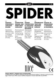
The pack contains the parts indicated in Figure 1 and described in Table 1.<br />
2<br />
1<br />
1<br />
Table 1 Parts list<br />
1. <strong>TTP</strong> palm-top programmer<br />
2. Motor connection cable<br />
Optional accessories<br />
<strong>TTP</strong>A1 rechargeable battery kit consisting of:<br />
• Pair of type AA 2000mAh Ni-MH batteries<br />
• 12V DC 300mA battery charger power supply unit<br />
2
3) Use<br />
The <strong>TTP</strong> programmer runs on type “AA” 1.5V batteries. Alternatively,<br />
you can use type “AA” 1.2V rechargeable batteries and charge<br />
them with the respective battery charger when necessary (see paragraph<br />
2.1) Components and accessories).<br />
To switch the <strong>TTP</strong> on, press the ON/OFF key; if the programmer is<br />
connected to a motor/control unit the available functions programmed<br />
in the motor/control unit are displayed immediately.<br />
If left idle, the programmer switches off automatically after 1 minute;<br />
to switch it off manually, hold the ON/OFF key down for a few seconds<br />
until the acoustic signal is emitted.<br />
GB<br />
3.1) Electrical connections<br />
The motor/control unit must be powered by connecting the mains supply line as set out in the instructions for the motor/control<br />
unit in question.<br />
<strong>TTP</strong> communicates with the motor/control unit via the TTBUS connection. It is therefore necessary to connect the cable supplied with <strong>TTP</strong><br />
to the inputs of the motor/control unit.<br />
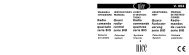
Connect only very low voltage cables to the <strong>TTP</strong>, adhering strictly to the polarity of the signals as shown in Figure 2.<br />
For motors fitted with a connection cable with 6 conductors, connect the cables marked with the green label:<br />
• black cable (COMMON – 0V) with the black cable of the <strong>TTP</strong><br />
• white cable (STEP-BY-STEP + TTBUS) with the white cable of the <strong>TTP</strong><br />
•orange cable (CLIMATIC SENSORS) with the orange cable of the <strong>TTP</strong><br />
For control units equipped with a terminal board, connect the inputs as follows:<br />
• COMMON – 0V ( ) with the black cable of the <strong>TTP</strong><br />
• STEP-BY-STEP + TTBUS (P/B) with the white cable of the <strong>TTP</strong><br />
• CLIMATIC SENSORS (S) with the orange cable of the <strong>TTP</strong><br />
!<br />
Connect only one motor/control unit to the <strong>TTP</strong> programmer at a time.<br />
! Adhere strictly to the connections specified; if in doubt, do not proceed by trial and error: consult the relevant technical<br />
schedules, which are also available at the site www.niceforyou.com.<br />
Incorrect connection can cause faults or dangerous situations.<br />
1 2 3 4 5 6 7 8 9 10 11 12 13 14 15<br />
C1 C2 L N CH P/B S<br />
L<br />
N<br />
L<br />
N<br />
WHITE<br />
ORANGE<br />
BLACK<br />
P/B<br />
S<br />
WHITE<br />
ORANGE<br />
BLACK<br />
WHITE<br />
ORANGE<br />
BLACK<br />
P/B<br />
S<br />
2<br />
Note: Throughout the rest of this document, the generic term “motor” will be used to describe any device which can be connected and configured<br />
with the <strong>TTP</strong> (whether a control unit or tubular motor).<br />
3
3.2) Keypad<br />
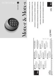
The appearance of the keypad of the <strong>TTP</strong> programmer is as shown in Figure 3. The keypad symbols and their meaning are described in<br />
Table 2.<br />
3<br />
Table 2 Key Description<br />
ON/OFF<br />
This key is for switching the <strong>TTP</strong> on and off, and searching for the connected motor.<br />
OPEN<br />
STOP<br />
CLOSE<br />
OK<br />
ANTICLOCKWISE<br />
CANCEL DIRECTION<br />
CLOCKWISE<br />
TORQUE REDUCTION<br />
Sends the ‘Open’ command (‘Up’ for awnings).<br />
This key is the equivalent of the ‘Open’ key on the remote control.<br />
Sends the ‘Stop’ command.<br />
This key is the equivalent of the ‘Stop’ key on the remote control.<br />
Sends the ‘Close’ command (‘Down’ for awnings).<br />
This key is the equivalent of the ‘Close’ key on the remote control.<br />
This key is for confirming all programming operations; the three LEDs associated with this<br />
key indicate the status of the operations in progress or of the communication between <strong>TTP</strong><br />
and motor.<br />
Programmes anticlockwise motor rotation.<br />
Cancels the settings for the direction of motor rotation.<br />
Programmes clockwise motor rotation.<br />
Enables/disables the torque reduction (RDC) function.<br />
POSITION “0” Memorises position “0”.<br />
POSITION “1” Memorises position “1”.<br />
INTERMEDIATE POSITION Memorises intermediate position “I”.<br />
POSITION 0 AND 1 Starts the automatic search procedure for positions “0” and “1”.<br />
AUTOMATIC SEARCH<br />
WIND THRESHOLD Displays and modifies the intervention threshold of the wind protection. Pressing the key repeatedly,<br />
enables you to move cyclically through all the thresholds permitted by the connected motor<br />
SUN THRESHOLD Displays and modifies the intervention threshold of the sun protection. Pressing the key repeatedly,<br />
enables you to move cyclically through all the thresholds permitted by the connected motor<br />
RAIN DIRECTION Displays and changes the direction of movement if the rain sensor is triggered.<br />
SENSORS ON/OFF<br />
CANCEL PARAMETERS<br />
MEMORIZE<br />
RADIO CONTROLS<br />
CANCEL RADIO<br />
CONTROLS<br />
Enables/disables intervention of the automated sun and rain systems<br />
Cancels the parameters of the motor and restores the factory settings.<br />
Memorizes a radio control in the motor memory.<br />
Cancels a radio control from the motor.<br />
4
READ PARAMETERS<br />
CANCEL PARAMETERS<br />
WRITE PARAMETERS<br />
F1 FUNCTION KEY<br />
F2 FUNCTION KEY<br />
F3 FUNCTION KEY<br />
Reads the parameters and/or radio controls of the connected motor and saves them to the<br />
<strong>TTP</strong> internal memory<br />
Cancels the parameters saved in the <strong>TTP</strong> internal memory<br />
Writes the parameters and/or radio controls in the connected motor by reading them from<br />
the <strong>TTP</strong> internal memory<br />
In conjunction with the “READ PARAMETERS” and “WRITE PARAMETERS” keys,<br />
memorizes the parameters relating to the positions.<br />
In conjunction with the “READ PARAMETERS” and “WRITE PARAMETERS” keys,<br />
memorizes the parameters relating to the wind, sun and rain sensors.<br />
In conjunction with the “READ PARAMETERS” and “WRITE PARAMETERS” keys,<br />
memorizes the radio controls.<br />
GB<br />
3.3) LEDs<br />
When the connected motor is correctly detected by the <strong>TTP</strong>, the LEDs for the available functions light up according to the following logic:<br />
1. LED flashing: the function is available but not yet programmed;<br />
2. LED steadily lit: the function is available and programmed;<br />
3. LED Off: the function is not available for that type of motor;<br />
The three LEDs associated with the OK key have a specific meaning: they indicate the status of the operations in progress and of the communication<br />
between <strong>TTP</strong> and motor, as shown in Table 3.<br />
Table 3 LED Description<br />
RED<br />
1. LED steadily lit: no motor connected, or serious communication errors have occurred, with the result<br />
that the motor has not been correctly recognised by the <strong>TTP</strong>;<br />
ORANGE<br />
GREEN<br />
1. LED flashes slowly: the motor search procedure is in progress;<br />
2. LED flashes quickly: memorizing of motor or radio control parameters is in progress;<br />
1. LED steadily lit: motor connected and correctly recognised;<br />
2. LED flashes slowly: <strong>TTP</strong> is waiting for the operator to press the OK key to confirm the operation;<br />
after 3 s the flashing stops and the operation is aborted.<br />
4) Functions<br />
Each key of the <strong>TTP</strong> programmer has a precise function assigned to<br />
it. The availability or unavailability of the functions and the procedure<br />
for their execution depends directly on the type of motor connected.<br />
For further details on programming procedures refer to the technical<br />
schedules, which are also available at the site “www.niceforyou.com”.<br />
4.1) ON/OFF key: switching ON, switching OFF and searching for the connected motor<br />
4.1.1) Switching on<br />
When you switch the <strong>TTP</strong> on, it checks for the presence of a connected motor. If the motor is detected, the LEDs for the functions available<br />
for programming light up; otherwise the unit beeps twice to indicate that the connection has not been made.<br />
Table 4 Switching on Example<br />
1. Press the ON/OFF key<br />
2. You will hear a long beep<br />
3. • If the motor is detected, the green OK LED and the LEDs for the functions available<br />
for programming light up<br />
• If the motor is not detected, the unit emits 2 short beeps and only the red OK LED<br />
lights up<br />
4.1.2) Switching off<br />
<strong>TTP</strong> switches off automatically after one minute if left idle; it can be switched off manually, however, using the procedure described in Table 5.<br />
Table 5 Switching off manually Example<br />
1. Hold the ON/OFF key down for about 3 seconds<br />
2. Release the key when the acoustic signal sounds and the red LED on the OK key starts<br />
flashing quickly.<br />
3s<br />
5
4.1.3) Searching for the motor<br />
Once the <strong>TTP</strong> is switched on, if you briefly press the ON/OFF key, the unit starts searching for any motor that may be connected. During the<br />
search (which may last several seconds) the orange OK LED flashes slowly. On completion of the search, if a motor is recognised, the LEDs<br />
for the functions available for programming light up. If no motor is detected, the error is indicated by an acoustic signal.<br />
Table 6 Searching for the motor Example<br />
1. Press the ON/OFF key<br />
2. The OK LED starts flashing slowly.<br />
3. Wait for the end of the search:<br />
• If the motor is detected, the green OK LED and the LEDs for the functions available<br />
for programming light up<br />
• If the motor is not detected, the unit emits 2 short beeps and only the red OK LED<br />
lights up<br />
Note: you can interrupt the search at any time by pressing the ON/OFF key again.<br />
4.2) Motor movement keys<br />
The , and keys are the equivalent of the keys on the transmitter and perform the functions set out in Table 7.<br />
Table 7 Movements Example<br />
1. Press ; the motor starts the UP manoeuvre.<br />
2. Press ; the motor stops the manoeuvre.<br />
3. Press ; the motor starts the DOWN manoeuvre.<br />
4. Press and simultaneously; if an intermediate position has been set, the motor will<br />
move to the set position.<br />
+<br />
4.3) Programming the direction of movement<br />
For motors with mechanical limit switch, you can quickly change the direction of movement of the motor by following the procedure described<br />
in Table 8.<br />
Table 8 Programming the direction Example<br />
1. If no direction has been programmed, the and keys do not control motor movements<br />
and the LEDs above the and keys flash simultaneously at very brief, regular intervals.<br />
2. Press the key for the direction you want.<br />
3. The green OK LED starts flashing: press OK within 3 seconds to confirm.<br />
3s<br />
4. On completion of the operation, the LED on the key corresponding to the direction you<br />
have chosen will light up.<br />
Note: after programming the direction of movement, check that the key on the transmitter does in fact open the shutter or pull up the<br />
awning, and that the key closes the shutter or pulls down the awning.<br />
If the devices do not operate in the direction you want, first cancel the direction and then reprogramme with the opposite direction.<br />
To cancel the direction, proceed as described in Table 9.<br />
Table 9 Cancelling the direction Example<br />
1. Press the ‘Cancel Direction’ key.<br />
or<br />
2. The green OK LED starts flashing: press OK within 3 seconds to confirm<br />
3. On completion of the operation, the LEDs above the and keys flash simultaneously<br />
at very brief, regular intervals.<br />
In order to control motor movements after cancelling the direction, it is necessary to repeat the procedure described in Table 8.<br />
3s<br />
4.4) Programming the positions<br />
On motors with electronic limit switch, functions are available for quick programming of positions 0 , 1 and I . If a position has already<br />
been set, the corresponding LED lights up, otherwise a short flash indicates that it has not yet been programmed.<br />
6
4.4.1) Manual programming of positions 0, 1 and I<br />
When setting the positions, follow the sequence: 0 1 I .<br />
! The procedure for setting the positions may differ according to the type of motor used; you are therefore advised to consult<br />
the technical schedules, which are also available at the site www.niceforyou.com for specific details and example for each type<br />
of motor.<br />
GB<br />
Table 10 Programming position 0 Example<br />
1. Press and hold down the or key until the shutter (awning) reaches the desired position.<br />
2. Press the key corresponding to position 0. The LED on the key starts flashing.<br />
or<br />
3. The green OK LED starts flashing: press OK within 3 seconds to confirm.<br />
4. On completion of the operation, the LED on the key for position 0 will light up.<br />
3s<br />
Note: the movement associated with the and keys may not be correct until you have set position 1.<br />
Note: on certain types of motor, changing position 0 may cancel positions 0 and I.<br />
Table 11 Programming position 1 Example<br />
1. Use the or keys to bring the shutter (awning) into the desired position.<br />
2. Press the key corresponding to position 1. The LED on the key starts flashing.<br />
or<br />
3. The green OK LED starts flashing: press OK within 3 seconds to confirm.<br />
4. On completion of the operation, the LED on the key for position 1 will light up.<br />
3s<br />
Note: changing position 1 cancels the intermediate position.<br />
Table 12 Programming the intermediate position Example<br />
1. Use the or keys to bring the shutter (awning) into the desired position.<br />
2. Press the key corresponding to the intermediate position. The LED on the key starts flashing.<br />
or<br />
3. The green OK LED starts flashing: press OK within 3 seconds to confirm.<br />
4. On completion of the operation, the LED on the key for the intermediate position will light up.<br />
3s<br />
Note: it is not possible to set the intermediate position if position 1 has not yet been set.<br />
4.4.2) Automatic programming of positions 0 and 1<br />
On some motors for shutters with electronic limit switch, a procedure is available for automatically detecting the travel limit positions. After<br />
switching on the <strong>TTP</strong>, if this function is available the LED on the “AUTO” key starts flashing.<br />
! This procedure can only be used if plugs for the UP phase and anti-intruder springs for the DOWN phase are fitted; for further<br />
details refer to the instructions for the motor.<br />
Table 13 Automatic search for positions 0 and 1 Example<br />
1. Press the “AUTO” key.<br />
2. The green OK LED starts flashing: press OK within 3 seconds to confirm.<br />
3. The motor indicates that the procedure has started by emitting 2 beeps.<br />
3s<br />
4. The shutter should move up; if it moves down, press or to reverse the direction.<br />
or<br />
5. At this point, the procedure continues automatically: first position “0” is located according to<br />
the position of the opening plugs and then position “1” is located according to the position<br />
of the anti-intruder closing springs.<br />
6. The procedure ends when the shutter is fully down and the unit emits 3 beeps.<br />
7. Press the ON/OFF key to display the new settings.<br />
7
4.4.3) Cancelling the memorized positions<br />
A previously memorized position can be cancelled by following the relevant procedure described in Table 14, Table 15 or Table 16.<br />
Table 14 Cancelling position 0 Example<br />
1. Press the key for position 0. The LED on the key flashes.<br />
2. Press the ‘Cancel’ key (bin). The LED on the key flashes.<br />
3. The green OK LED flashes: press OK within 3 seconds to confirm.<br />
4. On completion of the operation, the LED on the key for position 0 flashes.<br />
Note: on motors for shutters, cancelling position 0 also cancels the data for the other positions.<br />
3s<br />
Table 15 Cancelling position 1 Example<br />
1. Press the key for position 1. The LED on the key flashes.<br />
2. Press the ‘Cancel’ key (bin). The LED on the key starts flashing.<br />
3. The green OK LED flashes: press OK within 3 seconds to confirm.<br />
4. On completion of the operation, the LED on the key for position 1 flashes.<br />
Note: cancelling position 1 also cancels the intermediate position.<br />
3s<br />
Table 16 Cancelling the intermediate position Example<br />
1. Press the key for the intermediate position. The LED on the key flashes.<br />
2. Press the ‘Cancel’ key (bin). The LED on the key flashes.<br />
3. The green OK LED flashes: press OK within 3 seconds to confirm.<br />
4. On completion of the operation, the LED on the key for the intermediate position flashes.<br />
3s<br />
4.5) Programming torque reduction (RDC)<br />
Some motors are equipped with a “torque reduction” (RDC) function. If the RDC function is activated, the respective LED lights up, otherwise<br />
it remains OFF. If the function is not available for the type of motor connected, the key on the <strong>TTP</strong> is not active.<br />
Table 17 Enabling/disabling torque reduction Example<br />
1. Press the RDC key.<br />
2. The green OK LED starts flashing: press OK within 3 seconds to confirm.<br />
3s<br />
4.6) Programming the wind protection intervention threshold<br />
You can quickly change the wind sensor intervention threshold by following the procedure described in Table 18.<br />
Table 18 Selecting the wind protection intervention threshold Example<br />
1. Press the key repeatedly until the LED corresponding to the desired threshold lights up.<br />
2. The green OK LED starts flashing: press OK within 3 seconds to confirm.<br />
3s<br />
Note: The number of levels available depends on the motor connected; if the motor accepts 3 thresholds, therefore, the LEDs which light<br />
up in sequence are 1 2 3 1etc.<br />
4.7) Programming the sun protection intervention threshold<br />
You can quickly change the sun sensor intervention threshold by following the procedure described in Table 19.<br />
Table 19 Selecting the sun protection intervention threshold Example<br />
1. Press the key repeatedly until the LED corresponding to the desired threshold lights up.<br />
2. The green OK LED starts flashing: press OK within 3 seconds to confirm.<br />
3s<br />
Note: The number of levels available depends on the motor connected; if the motor accepts 3 thresholds, therefore, the LEDs which light<br />
up in sequence are 1 2 3 1 etc.<br />
8
4.8) Programming the rain intervention direction<br />
You can quickly change the direction of movement in the event of intervention of the rain sensor by following the procedure described in Table<br />
20.<br />
GB<br />
Table 20 Selecting the rain intervention direction Example<br />
1. Press the key to reverse the rain intervention direction.<br />
2. The green OK LED starts flashing: press OK within 3 seconds to confirm.<br />
3s<br />
4.9) Enabling/disabling the sensors<br />
This key is for enabling/disabling the intervention of the automated sun and rain systems. If the function is activated the respective LED lights<br />
up, otherwise it remains OFF.<br />
Table 21 Enabling/disabling the automated sun and rain systems Example<br />
1. Press the key to enable/disable the sensors.<br />
2. The green OK LED starts flashing: press OK within 3 seconds to confirm.<br />
3s<br />
4.10) Cancelling the parameter memory<br />
This procedure enables you to cancel all the parameters stored in the motor memory and restore the factory settings.<br />
Table 22 Cancelling the parameter memory Example<br />
1. Hold down the ‘Cancel’ key (bin) for about 3 seconds until the respective LED starts flashing.<br />
2. The green OK LED starts flashing: press OK within 3 seconds to confirm.<br />
Note: this procedure does not cancel the radio controls; for this function see paragraph 4.13) Cancelling all radio controls.<br />
3s<br />
4.11) Entering the radio controls<br />
You can quickly enter a radio control by following the procedure described in Table 23.<br />
Table 23 Entering a radio control Example<br />
1. Press the ‘Save radio control’ key. The LED above the key will start flashing slowly to<br />
indicate that the unit is waiting to receive a radio control.<br />
2. Within 5 seconds press any key on the radio control to be entered.<br />
3. If the radio control is received correctly, the LED on the key flashes quickly.<br />
4. The green OK LED starts flashing: press OK within 3 seconds to confirm.<br />
5s<br />
3s<br />
4.12) Cancelling a radio control<br />
You can quickly cancel a memorized radio control by following the procedure described in Table 24.<br />
Table 24 Cancelling a radio control Example<br />
1. Press the ‘Cancel radio control’ key. The LED above the key will start flashing slowly to<br />
indicate that the unit is waiting to receive a radio control<br />
2. Within 5 seconds press any key on the radio control to be removed.<br />
3. If the code is received correctly the LED on the key flashes quickly.<br />
4. The green OK LED starts flashing: press OK within 3 seconds to confirm.<br />
5s<br />
3s<br />
9
4.13) Cancelling all radio controls<br />
This procedure cancels all the radio controls saved in the memory.<br />
Table 25 Cancelling all radio controls Example<br />
1. Hold down the ‘Cancel radio control’ key for about 3 seconds until the respective LED<br />
starts flashing.<br />
2. The green OK LED starts flashing: press OK within 3 seconds to confirm.<br />
3s<br />
3s<br />
4.14) Copying parameters and radio controls<br />
By using a combination of keys, it is possible to read the parameters and radio controls of a motor and save them in the memory of the <strong>TTP</strong><br />
programmer. This data can then be transferred to other motors of the same type.<br />
4.14.1) Reading the motor parameters<br />
To read the parameters, proceed as described in Table 26.<br />
! In order to prevent accidental cancellation or overwriting of the <strong>TTP</strong> memory, the motor parameter reading procedure can<br />
only be executed if the <strong>TTP</strong> memory has been previously cancelled by means of the appropriate procedure (see Table 28).<br />
Table 26 Motor parameter reading Example<br />
1. Press the “READ PARAMETERS” key.<br />
2. Press one or more keys (“F1”, “F2”, “F3”) according to the data you want to copy:<br />
• F1 reads the parameters for direction of rotation and travel limits<br />
• F2 reads the parameters for sensors (wind and sun thresholds, etc.)<br />
• F3 reads the radio controls<br />
3. The green OK LED starts flashing: press OK within 3 seconds to confirm.<br />
3s<br />
4.14.2) Writing parameters to the motor<br />
To transfer the previously saved parameters, proceed as described in Table 27.<br />
Table 27 Transferring parameters to the motor Example<br />
1. Press the “WRITE PARAMETERS” key.<br />
2. Press one or more keys (“F1”, “F2”, “F3”) according to the data you want to programme:<br />
• F1 enters the parameters for direction of rotation and heights<br />
• F2 enters the parameters for the sensors<br />
• F3 enters the radio controls<br />
3. The green OK LED starts flashing: press OK within 3 seconds to confirm.<br />
3s<br />
!<br />
The parameters can be transferred only if the motor is of the same type as the motor which has been read.<br />
4.14.3) Cancelling parameters memorized in the <strong>TTP</strong> memory<br />
To cancel parameters saved in the <strong>TTP</strong> memory, proceed as described in Table 28.<br />
Table 28 Cancelling the <strong>TTP</strong> memory Example<br />
1. Press the “CANCEL PARAMETERS” key.<br />
2. Press the keys “F1”, “F2” and “F3” in sequence<br />
3. The green OK LED starts flashing: press OK within 3 seconds to confirm.<br />
3s<br />
10
5) Maintenance<br />
The <strong>TTP</strong> programmer does not normally require any type of maintenance<br />
as it does not contain parts subject to wear. Only the batteries<br />
need to be replaced periodically (or recharged in the case of<br />
rechargeable batteries).<br />
When the batteries are discharged, the <strong>TTP</strong> emits a long beep at<br />
intervals of about 10 seconds; on the third beep, the <strong>TTP</strong> switches<br />
off automatically.<br />
GB<br />
5.1) Replacing the batteries<br />
If you use non-rechargeable batteries, remove the panel on the bottom<br />
of the box and replace the batteries, taking care to adhere to the<br />
polarity marked on the bottom of the battery compartment.<br />
5.2) Disposal of the batteries<br />
Discharged batteries are highly polluting and it is therefore compulsory<br />
to dispose of them in the appropriate disposal containers.<br />
5.3) Recharging the batteries<br />
If you use rechargeable batteries, recharge them by connecting the<br />
battery charger to a power socket and then to the <strong>TTP</strong>. Leave to<br />
recharge for about 15 hours, then disconnect. If the time for which<br />
the batteries retain their charge decreases significantly, they have<br />
deteriorated and should be replaced.<br />
! Do not attempt to recharge ordinary alkaline batteries. If<br />
you want to power the <strong>TTP</strong> with the battery charger power<br />
supply unit it is advisable to remove the batteries.<br />
5.4) Environmental protection measures<br />
This product consists of various types of materials, some of which<br />
can be recycled.<br />
! Some components may contain polluting substances. Do<br />
not discard this product as ordinary refuse but find out about<br />
the recycling or disposal systems for the product and comply<br />
with the methods prescribed in local regulations.<br />
6) Technical specifications<br />
Type<br />
Programming unit for control units and motors predisposed for TTBUS connection<br />
Power supply<br />
Internal: 2 type AA 1.5V batteries, or 2 type AA 1.2V, 2000mAh rechargeable batteries<br />
External: 12V DC, 300 mA battery charger power supply unit<br />
Battery life<br />
Estimated as approximately 20 operating hours<br />
Operating temperature -20°C + 55°C<br />
Protection class<br />
IP 20 (only for use in sheltered environments)<br />
Dimensions and weight 155 X 96 X 28,2h / 220g<br />
<strong>Nice</strong> S.p.A. reserves the right to modify its products at any time it deems necessary.<br />
EC Declaration of conformity<br />
IN ACCORDANCE WITH DIRECTIVE 89/336/EEC<br />
Number: 182/<strong>TTP</strong> Date: 30/03/2004 Revision: 0<br />
The undersigned Lauro Buoro, Managing Director, hereby declares that the product:<br />
Manufacturer’s name NICE S.p.A.<br />
Address<br />
Via Pezza Alta 13, 31046 Z.I. Rustignè –ODERZO- ITALY<br />
Model<br />
<strong>TTP</strong><br />
meets the essential requirements of Directive 89/336/EEC relating to electromagnetic compatibility.<br />
ODERZO, 30-03-2004<br />
(Managing Director)<br />
Lauro Buoro<br />
11
1) Avvertenze<br />
Questo manuale si riferisce alla unità di programmazione <strong>TTP</strong>. Nell’uso di<br />
<strong>TTP</strong> occorre considerare che il collegamento a tipi diversi di motori/centrali<br />
può comportare qualche differenza nell’esecuzione delle procedure<br />
di programmazione; per approfondimenti consultare le apposite schede<br />
tecniche disponibili anche sul sito www.niceforyou.com.<br />
Rivolgersi a personale tecnico competente per manutenzioni e riparazioni.<br />
2) Descrizione del prodotto<br />
Il programmatore <strong>TTP</strong> è una unità logica studiata da <strong>Nice</strong> per semplificare<br />
le operazioni di installazione, collaudo e manutenzione dei<br />
motori e centrali. <strong>TTP</strong> attraverso la comunicazione TTBUS consente<br />
di svolgere in modo rapido e intuitivo le procedure normalmente<br />
svolte con il telecomando. Ogni altro uso è improprio e vietato.<br />
La funzione fondamentale del programmatore è quella di agire direttamente<br />
nei motori/centrali nei quali sono memorizzati i parametri di<br />
funzionamento ed i radiocomandi. Sono disponibili anche altre funzioni<br />
accessorie come la possibilità di leggere la configurazione di un<br />
motore/centrale (parametri e/o radiocomandi) per copiarla in uno o<br />
più motori/centrali.<br />
2.1) Componenti e accessori<br />
Nella confezione sono contenute le parti indicate in Figura 1 e descritte in Tabella 1.<br />
2<br />
1<br />
1<br />
Tabella 1 Elenco parti<br />
1. Programmatore palmare <strong>TTP</strong><br />
2. Cavo di collegamento motore<br />
Accessori opzionali<br />
Kit batterie ricaricabili <strong>TTP</strong>A1 composto da:<br />
• Coppia di batterie Ni-MH tipo AA 2000mAh<br />
• Alimentatore caricabatteria 12Vdc 300mA<br />
12
3) Utilizzo<br />
Il programmatore <strong>TTP</strong> funziona con batterie tipo “AA” da 1,5V. In<br />
alternativa si possono utilizzare batterie ricaricabili tipo “AA” da 1,2V<br />
ed all’occorrenza ricaricarle con il relativo caricabatteria (vedere il<br />
paragrafo 2.1) Componenti e accessori).<br />
Se non usato, il programmatore si spegne automaticamente dopo 1<br />
minuto; per spegnerlo prima basta tener premuto il tasto ON/OFF<br />
per qualche secondo fino all’emissione del segnale acustico.<br />
Per accendere <strong>TTP</strong> premere il tasto ON/OFF; se il programmatore è<br />
collegato ad un motore/centrale vengono immediatamente visualizzate<br />
le funzioni disponibili e programmate nel motore/centrale.<br />
I<br />
3.1) Collegamenti elettrici<br />
Il motore/centrale deve essere alimentato collegando la linea di alimentazione da rete elettrica come previsto nelle istruzioni<br />
del motore/centrale in oggetto.<br />
<strong>TTP</strong> comunica con il motore/centrale attraverso il collegamento TTBUS, è necessario quindi collegare i morsetti del cavo fornito in dotazione<br />
a <strong>TTP</strong> con gli ingressi del motore/centrale.<br />
I cavi da collegare a <strong>TTP</strong> sono esclusivamente quelli in bassissima tensione, rispettando rigorosamente la polarità dei segnali come indicato<br />
in Figura 2.<br />
Nei motori provvisti di cavo di collegamento a 6 conduttori collegare i cavi contrassegnati con l’etichetta verde:<br />
• cavo nero (COMUNE - 0V) con il cavo nero di <strong>TTP</strong><br />
• cavo bianco (PASSO-PASSO + TTBUS) con il cavo bianco di <strong>TTP</strong><br />
• cavo arancione (SENSORI CLIMATICI) con il cavo arancione di <strong>TTP</strong><br />
Nelle centrali dotate di morsettiera collegare gli ingressi:<br />
• COMUNE - 0V ( ) con il cavo nero di <strong>TTP</strong><br />
•PASSO-PASSO + TTBUS (P/B) con il cavo bianco di <strong>TTP</strong><br />
• SENSORI CLIMATICI (S) con il cavo arancione di <strong>TTP</strong><br />
!<br />
Collegare un solo motore/centrale alla volta al programmatore <strong>TTP</strong>.<br />
! Rispettare scrupolosamente i collegamenti previsti; in caso di dubbio non tentare invano ma consultare le apposite schede<br />
tecniche di approfondimento disponibili anche sul sito www.niceforyou.com.<br />
Un collegamento errato può provocare guasti o situazioni di pericolo.<br />
1 2 3 4 5 6 7 8 9 10 11 12 13 14 15<br />
C1 C2 L N CH P/B S<br />
L<br />
L<br />
N<br />
N<br />
BIANCO<br />
ARANCIONE<br />
NERO<br />
P/B<br />
S<br />
BIANCO<br />
ARANCIONE<br />
NERO<br />
BIANCO<br />
ARANCIONE<br />
NERO<br />
P/B<br />
S<br />
2<br />
Nota: D’ora in poi chiameremo genericamente “motore” qualsiasi dispositivo che è possibile collegare e configurare con <strong>TTP</strong> (sia esso una<br />
centralina di controllo o motore tubolare).<br />
13
3.2) Tastiera<br />
La tastiera del programmatore <strong>TTP</strong> si presenta come illustrato in Figura 3. In Tabella 2 sono descritti i simboli della tastiera ed il loro significato.<br />
3<br />
Tabella 2 Tasto Descrizione<br />
ON/OFF<br />
APRE<br />
STOP<br />
CHIUDE<br />
OK<br />
Questo tasto serve per accendere e spegnere <strong>TTP</strong> ed eseguire la ricerca del motore<br />
collegato.<br />
Invia il comando di apertura (salita per le tende).<br />
Questo tasto è equivalente al tasto di apertura sul telecomando.<br />
Invia il comando di arresto.<br />
Questo tasto è equivalente al tasto stop sul telecomando.<br />
Invia il comando di chiusura (discesa per le tende).<br />
Questo tasto è equivalente al tasto di chiusura sul telecomando.<br />
Serve a confermare ogni attività di programmazione; i tre led associati a questo tasto<br />
indicano lo stato delle operazioni in corso o della comunicazione fra <strong>TTP</strong> e il motore.<br />
DIREZIONE ANTIORARIA<br />
CANCELLA DIREZIONE<br />
DIREZIONE ORARIA<br />
RIDUZIONE DI COPPIA<br />
Programma il verso di rotazione del motore in senso antiorario.<br />
Cancella le impostazioni relative al verso di rotazione del motore.<br />
Programma il verso di rotazione del motore in senso orario.<br />
Abilita/disabilita la funzione di riduzione di coppia RDC.<br />
POSIZIONE “0” Memorizza la posizione “0”.<br />
POSIZIONE “1” Memorizza la posizione “1”.<br />
POSIZIONE INTERMEDIA<br />
Memorizza la posizione intermedia “I”.<br />
RICERCA AUTOMATICA Avvia la procedura di ricerca automatica delle posizioni “0” e “1”.<br />
POSIZIONI 0 E 1<br />
LIVELLO VENTO<br />
Visualizza e modifica il livello di intervento della protezione vento. Pressioni successive<br />
del tasto consentono di muoversi ciclicamente fra tutti i livelli consentiti dal motore collegato<br />
LIVELLO SOLE<br />
Visualizza e modifica il livello di intervento della protezione sole. Pressioni successive del<br />
tasto consentono di muoversi ciclicamente fra tutti i livelli consentiti dal motore collegato<br />
DIREZIONE PIOGGIA Visualizza e modifica la direzione del movimento in caso di intervento del sensore pioggia.<br />
SENSORI ON/OFF<br />
CANCELLAZIONE<br />
PARAMETRI<br />
MEMORIZZAZIONE<br />
RADIOCOMANDI<br />
CANCELLAZIONE<br />
RADIOCOMANDI<br />
Abilita/disabilita l’intervento degli automatismi sole e pioggia<br />
Cancella i parametri del motore ripristinando le impostazioni di fabbrica.<br />
Memorizza un radiocomando nel motore.<br />
Cancella un radiocomando dal motore.<br />
14
LEGGI PARAMETRI<br />
CANCELLA PARAMETRI<br />
SCRIVI PARAMETRI<br />
TASTO FUNZIONE F1<br />
TASTO FUNZIONE F2<br />
TASTO FUNZIONE F3<br />
Legge i parametri e/o radiocomandi del motore collegato e li salva nella memoria interna a<br />
<strong>TTP</strong><br />
Cancella i parametri memorizzati nella memoria interna a <strong>TTP</strong><br />
Scrive i parametri e/o radiocomandi nel motore collegato leggendoli dalla memoria interna a<br />
<strong>TTP</strong><br />
In associazione con i tasti “LEGGI PARAMETRI” e “SCRIVI PARAMETRI” memorizza i<br />
parametri relativi alle posizioni.<br />
In associazione con i tasti “LEGGI PARAMETRI” e “SCRIVI PARAMETRI” memorizza i<br />
parametri relativi ai sensori vento, sole, pioggia.<br />
In associazione con i tasti “LEGGI PARAMETRI” e “SCRIVI PARAMETRI” memorizza i<br />
radiocomandi.<br />
I<br />
3.3) Led<br />
Quando il motore collegato viene correttamente rilevato da <strong>TTP</strong> si accendono i led relativi alle funzioni disponibili secondo la logica che segue:<br />
1. il led lampeggia: la funzione è disponibile ma non ancora programmata;<br />
2. il led è acceso fisso: la funzione è disponibile e programmata;<br />
3. il led è spento: la funzione non è disponibile per il tipo di motore;<br />
Un significato particolare hanno i tre led associati al tasto OK, indicano infatti lo stato delle operazioni in corso e della comunicazione fra <strong>TTP</strong><br />
e motore, come illustrato in Tabella 3.<br />
Tabella 3 Led Descrizione<br />
ROSSO<br />
1. il led è acceso fisso: nessun motore collegato, o si sono verificati errori gravi di<br />
comunicazione per cui il motore non è stato correttamente riconosciuto da <strong>TTP</strong>;<br />
ARANCIONE<br />
VERDE<br />
1. il led lampeggia lentamente: è in corso la procedura di ricerca del motore;<br />
2. il led lampeggia velocemente: è in corso la memorizzazione dei parametri motore o dei<br />
radiocomandi;<br />
1. il led è acceso fisso: motore collegato e correttamente riconosciuto;<br />
2. il led lampeggia lentamente: <strong>TTP</strong> attende la pressione del tasto OK per la conferma dell’operazione<br />
da parte dell’operatore; dopo 3 s il lampeggio termina e l’operazione viene abortita.<br />
4) Funzioni<br />
Ad ogni tasto del programmatore <strong>TTP</strong> è associata una precisa funzione.<br />
La disponibilità o meno delle funzioni così come la loro modalità<br />
di esecuzione è strettamente legata al tipo di motore collegato.<br />
Per maggiori dettagli sulle procedure di programmazione fare riferimento<br />
alle schede tecniche di approfondimento disponibili anche sul<br />
sito “www.niceforyou.com”.<br />
4.1) Tasto ON/OFF: accensione, spegnimento e ricerca del motore collegato<br />
4.1.1) Accensione<br />
All’accensione <strong>TTP</strong> esegue un controllo per verificare la presenza di un motore collegato. Se il motore viene rilevato i led relativi alle programmazioni<br />
disponibili si accendono, altrimenti due bip brevi segnalano la mancata connessione.<br />
Tabella 4 Accensione Esempio<br />
1. Premere il tasto ON/OFF<br />
2. Si sentirà un bip lungo<br />
3. • Se il motore viene rilevato si accendono il led OK verde ed i led delle programmazioni<br />
possibili<br />
• Se il motore non viene rilevato vengono emessi 2 bip brevi ed il solo led OK rosso si<br />
accende<br />
4.1.2) Spegnimento<br />
<strong>TTP</strong> si spegne automaticamente dopo un minuto di inattività, tuttavia è possibile spegnerla manualmente con la procedura descritta in Tabella<br />
5.<br />
Tabella 5 Spegnimento manuale Esempio<br />
1. Tenere premuto il tasto ON/OFF per circa 3 secondi<br />
2. Rilasciare il tasto quando viene emesso un segnale acustico e il led rosso sul tasto OK<br />
comincia a lampeggiare velocemente.<br />
3s<br />
15
4.1.3) Ricerca motore<br />
Quando <strong>TTP</strong> è già accesa, una breve pressione del tasto ON/OFF riavvia la ricerca di un eventuale motore collegato. Durante questo periodo<br />
(che può durare diversi secondi) il led OK arancione lampeggia lentamente. Al termine della ricerca se un motore viene riconosciuto i led<br />
relativi alle funzioni programmabili si accendono. Se invece nessun motore viene rilevato un segnale acustico segnala l’errore.<br />
Tabella 6 Ricerca motore Esempio<br />
1. Premere il tasto ON/OFF<br />
2. Il led OK arancione comincia a lampeggiare lentamente.<br />
3. Attendere il termine della ricerca:<br />
• Se il motore viene rilevato si accendono il led OK verde ed i led delle programmazioni<br />
possibili<br />
• Se il motore non viene rilevato vengono emessi 2 bip brevi ed il solo led OK rosso si<br />
accende<br />
Nota: è possibile in ogni momento interrompere la ricerca premendo nuovamente il tasto ON/OFF.<br />
4.2) Tasti di movimento motore<br />
I tasti , , sono equivalenti ai tasti del trasmettitore e svolgono le funzioni elencate in Tabella 7.<br />
Tabella 7 Movimenti Esempio<br />
1. Premere il tasto , il motore inizia la manovra di salita.<br />
2. Premere il tasto , il motore arresta il movimento.<br />
3. Premere il tasto , il motore inizia la manovra di discesa.<br />
4. Premere contemporaneamente i tasti e ; se la posizione intermedia è stata<br />
programmata il motore si sposterà alla posizione memorizzata.<br />
+<br />
4.3) Programmazione della direzione del movimento<br />
Nei motori con finecorsa meccanico è possibile modificare velocemente la direzione del movimento del motore seguendo la procedura<br />
descritta in Tabella 8.<br />
Tabella 8 Programmazione della direzione Esempio<br />
1. Se la direzione non è programmata i tasti e non comandano i movimenti<br />
motore ed i led sopra i tasti e lampeggiano contemporaneamente ad intervalli<br />
regolari e molto brevi.<br />
2. Premere il tasto della direzione desiderata.<br />
3. Il led OK verde comincia a lampeggiare: confermare con il tasto OK entro 3 secondi.<br />
4. Al termine dell’operazione il led sul tasto relativo alla direzione scelta sarà acceso.<br />
o<br />
3s<br />
Nota: dopo aver programmato la direzione del movimento verificare che il tasto del trasmettitore comandi effettivamente l’apertura<br />
della tapparella o il ritiro della tenda, mentre il tasto comandi la chiusura della tapparella o la discesa della tenda.<br />
Se la direzione non è quella desiderata è necessario prima cancellarla e successivamente riprogrammarla nel verso opposto.<br />
Per cancellare la direzione procedere come descritto in Tabella 9.<br />
Tabella 9 Cancellazione della direzione Esempio<br />
1. Premere il tasto di cancellazione della direzione.<br />
2. Il led OK verde comincia a lampeggiare: confermare con il tasto OK entro 3 secondi<br />
3. Al termine dell’operazione i led sopra i tasti e lampeggiano contemporaneamente ad<br />
intervalli regolari e molto brevi.<br />
Dopo aver cancellato la direzione per poter comandare i movimenti motore è necessario ripetere la procedura descritta in Tabella 8.<br />
3s<br />
4.4) Programmazione delle posizioni<br />
Nei motori con finecorsa elettronico sono disponibili le funzioni che consentono di programmare velocemente le posizioni 0 , 1 e I .<br />
Se una posizione è già memorizzata il led corrispondente è acceso, altrimenti un lampeggio breve indica che non è ancora stata programmata.<br />
16
4.4.1) Programmazione manuale delle posizioni 0, 1 e I<br />
La sequenza da seguire nella memorizzazione delle posizioni è: 0 1 I .<br />
! La procedura di memorizzazione delle posizioni potrebbe variare in relazione al tipo di motore utilizzato, pertanto si rimanda<br />
alle schede tecniche di approfondimento disponibili anche sul sito www.niceforyou.com per dettagli ed esempi specifici per<br />
ogni tipo di motore.<br />
Tabella 10 Programmazione della posizione 0 Esempio<br />
1. Premere e tenere premuto il tasto o il tasto fino a portare la tapparella (tenda) nella<br />
posizione desiderata.<br />
2. Premere il tasto relativo alla posizione 0. Il led sul tasto lampeggia.<br />
o<br />
I<br />
3. Il led OK verde comincia a lampeggiare: confermare con il tasto OK entro 3 secondi.<br />
4. Al termine dell’operazione il led sul tasto relativo alla posizione 0 sarà acceso.<br />
3s<br />
Nota: il movimento associato ai tasti e potrebbe non essere corretto fino a che non si memorizza la posizione 1.<br />
Nota: in alcuni tipi di motori la modifica della posizione 0 potrebbe cancellare le posizioni 0 e I.<br />
Tabella 11 Programmazione della posizione 1 Esempio<br />
1. Utilizzare i tasti o fino a portare la tapparella (tenda) nella posizione desiderata.<br />
2. Premere il tasto relativo alla posizione 1. Il led sul tasto lampeggia.<br />
o<br />
3. Il led OK verde comincia a lampeggiare: confermare con il tasto OK entro 3 secondi.<br />
4. Al termine dell’operazione il led sul tasto relativo alla posizione 1 sarà acceso.<br />
3s<br />
Nota: La modifica della posizione 1 cancella la posizione intermedia.<br />
Tabella 12 Programmazione della posizione intermedia Esempio<br />
1. Utilizzare i tasti o per portare la tapparella (tenda) nella posizione desiderata.<br />
2. Premere il tasto relativo alla posizione intermedia. Il led sul tasto lampeggia.<br />
o<br />
3. Il led OK verde comincia a lampeggiare: confermare con il tasto OK entro 3 secondi.<br />
4. Al termine dell’operazione il led sul tasto relativo alla posizione intermedia sarà acceso.<br />
3s<br />
Nota: Non è possibile memorizzare la posizione intermedia se precedentemente non è stata memorizzata la posizione 1.<br />
4.4.2) Programmazione automatica delle posizioni 0 e 1<br />
In alcuni motori per tapparelle con finecorsa elettronico è disponibile un procedura che rileva automaticamente le posizioni dei fine corsa. Se<br />
questa funzionalità è disponibile dopo aver acceso <strong>TTP</strong> il led sul tasto “AUTO” lampeggia.<br />
! Per eseguire questa procedura è necessaria la presenza dei tappi in salita e delle molle anti-intrusione in discesa; per maggiori<br />
dettagli fare riferimento alle istruzioni del motore.<br />
Tabella 13 Ricerca automatica delle posizioni 0 e 1 Esempio<br />
1. Premere il tasto “AUTO”.<br />
2. Il led OK verde comincia a lampeggiare: confermare con il tasto OK entro 3 secondi.<br />
3. Il motore segnala l’avvio della procedura emettendo 2 bip.<br />
3s<br />
4. La tapparella dovrà muoversi verso l’alto, se il movimento è verso il basso premere<br />
il tasto o per invertire la direzione.<br />
5. La procedura a questo punto proseguirà automaticamente:<br />
prima verrà trovata la posizione “0” in corrispondenza dei tappi in apertura e<br />
successivamente la posizione “1” in corrispondenza delle molle anti-intrusione in chiusura.<br />
6. La procedura si concluderà con la tapparella completamente chiusa e con una<br />
segnalazione sonora di 3 bip.<br />
7. Premere il tasto ON/OFF per visualizzare le nuove impostazioni.<br />
o<br />
17
4.4.3) Cancellazione delle posizioni memorizzate<br />
La cancellazione di una posizione già programmata è possibile seguendo la procedura corrispondente descritta in Tabella 14, Tabella 15 o<br />
Tabella 16.<br />
Tabella 14 Cancellazione della posizione 0 Esempio<br />
1. Premere il tasto relativo alla posizione 0. Il led sul tasto lampeggia.<br />
2. Premere il tasto di cancellazione (cestino). Il led sul tasto lampeggia.<br />
3. Il led OK verde lampeggia: confermare con il tasto OK entro 3 secondi.<br />
4. Al termine dell’operazione il led sul tasto relativo alla posizione 0 lampeggia.<br />
Nota: nei motori per tapparelle la cancellazione della posizione 0 cancella anche le informazioni relative alle altre posizioni.<br />
3s<br />
Tabella 15 Cancellazione della posizione 1 Esempio<br />
1. Premere il tasto relativo alla posizione 1. Il led sul tasto lampeggia.<br />
2. Premere il tasto di cancellazione (cestino). Il led sul tasto lampeggia.<br />
3. Il led OK verde lampeggia: confermare con il tasto OK entro 3 secondi.<br />
4. Al termine dell’operazione il led sul tasto relativo alla posizione 1 lampeggia.<br />
Nota: La cancellazione della posizione 1 cancella anche la posizione intermedia.<br />
3s<br />
Tabella 16 Cancellazione della posizione intermedia Esempio<br />
1. Premere il tasto relativo alla posizione intermedia. Il led sul tasto lampeggia.<br />
2. Premere il tasto di cancellazione (cestino). Il led sul tasto lampeggia.<br />
3. Il led OK verde comincia a lampeggiare: confermare con il tasto OK entro 3 secondi.<br />
4. Al termine dell’operazione il led sul tasto relativo alla posizione intermedia lampeggia.<br />
3s<br />
4.5) Programmazione della riduzione di coppia (RDC)<br />
Alcuni motori dispongono della funzione “riduzione di coppia” (RDC). Se la RDC è attivata il led relativo è acceso, altrimenti è spento. Se per<br />
il tipo di motore collegato la funzione non è disponibile il tasto su <strong>TTP</strong> non è attivo.<br />
Tabella 17 Attivazione/disattivazione della riduzione di coppia Esempio<br />
1. Premere il tasto relativo alla RDC.<br />
2. Il led OK verde comincia a lampeggiare: confermare con il tasto OK entro 3 secondi.<br />
3s<br />
4.6) Programmazione del livello di intervento della protezione vento<br />
E’ possibile modificare rapidamente il livello di intervento del sensore vento seguendo la procedura descritta in Tabella 18.<br />
Tabella 18 Selezione del livello di intervento vento Esempio<br />
1. Premere ripetutamente il tasto fino ad accendere il led corrispondente al livello desiderato.<br />
2. Il led OK verde comincia a lampeggiare: confermare con il tasto OK entro 3 secondi.<br />
3s<br />
Nota: Il numero di livelli disponibili dipende dal motore collegato; pertanto se i livelli accettati dal motore sono 3, i led che si accendono in<br />
sequenza sono 1 2 3 1…<br />
4.7) Programmazione del livello di intervento della protezione sole<br />
E’ possibile modificare rapidamente il livello di intervento del sensore sole seguendo la procedura descritta in Tabella 19.<br />
Tabella 19 Selezione del livello di intervento sole Esempio<br />
1. Premere ripetutamente il tasto fino ad accendere il led corrispondente al livello desiderato<br />
2. Il led OK verde comincia a lampeggiare: confermare con il tasto OK entro 3 secondi.<br />
3s<br />
Nota: Il numero di livelli disponibili dipende dal motore collegato; pertanto se i livelli accettati dal motore sono 3, i led che si accendono in<br />
sequenza sono 1 2 3 1…<br />
18
4.8) Programmazione della direzione intervento pioggia<br />
E’ possibile modificare rapidamente la direzione del movimento in caso di intervento del sensore pioggia seguendo la procedura descritta in<br />
Tabella 20.<br />
Tabella 20 Selezione della direzione intervento pioggia Esempio<br />
1. Premere il tasto per invertire la direzione di intervento pioggia.<br />
2. Il led OK verde comincia a lampeggiare: confermare con il tasto OK entro 3 secondi.<br />
3s<br />
I<br />
4.9) Attivazione/disattivazione sensori<br />
Questo tasto consente di abilitare/disabilitare l’intervento degli automatismi sole e pioggia. Se la funzione è attivata il led relativo è acceso,<br />
altrimenti è spento.<br />
Tabella 21 Attivazione/disattivazione degli automatismi sole e pioggia Esempio<br />
1. Premere il tasto per attivare/disattivare i sensori.<br />
2. Il led OK verde comincia a lampeggiare: confermare con il tasto OK entro 3 secondi.<br />
3s<br />
4.10) Cancellazione memoria parametri<br />
Questa procedura consente di cancellare tutti i parametri contenuti nella memoria del motore e riportarla alle impostazioni di fabbrica.<br />
Tabella 22 Cancellazione memoria parametri Esempio<br />
1. Premere e tenere premuto il tasto di cancellazione (cestino) per circa 3 secondi fino a<br />
quando il led relativo comincia a lampeggiare.<br />
2. Il led OK verde comincia a lampeggiare: confermare con il tasto OK entro 3 secondi.<br />
3s<br />
Nota: questa procedura non cancella i radiocomandi, per questa funzione vedere il paragrafo 4.13) Cancellazione di tutti i radiocomandi<br />
4.11) Inserimento dei radiocomandi<br />
E’ possibile inserire rapidamente un radiocomando seguendo la procedura descritta in Tabella 23.<br />
Tabella 23 Inserimento radiocomando Esempio<br />
1. Premere il tasto di inserimento radiocomando. Il led sopra il tasto inizierà a lampeggiare<br />
lentamente in attesa di ricevere un radiocomando.<br />
2. Entro 5 secondi premere un pulsante qualsiasi del radiocomando da inserire.<br />
3. Se il radiocomando viene ricevuto correttamente il led sul tasto lampeggia velocemente.<br />
4. Il led OK verde comincia a lampeggiare: confermare con il tasto OK entro 3 secondi.<br />
5s<br />
3s<br />
4.12) Cancellazione di un radiocomando<br />
E’ possibile cancellare rapidamente un radiocomando memorizzato seguendo la procedura descritta in Tabella 24.<br />
Tabella 24 Cancellazione di un radiocomando Esempio<br />
1. Premere il tasto di cancellazione radiocomando.<br />
Il led sopra il tasto inizierà a lampeggiare lentamente in attesa di ricevere un radiocomando<br />
2. Entro 5 secondi premere un pulsante qualsiasi del radiocomando da eliminare.<br />
3. Se il codice viene ricevuto correttamente il led sul tasto lampeggia velocemente.<br />
4. Il led OK verde comincia a lampeggiare: confermare con il tasto OK entro 3 secondi.<br />
5s<br />
3s<br />
19
4.13) Cancellazione di tutti i radiocomandi<br />
Questa procedura consente di cancellare tutti i radiocomandi memorizzati.<br />
Tabella 25 Cancellazione di tutti i radiocomandi Esempio<br />
1. Premere e tenere premuto il tasto di cancellazione radiocomando per circa 3 secondi fino a<br />
quando il led relativo comincia a lampeggiare.<br />
2. Il led OK verde comincia a lampeggiare: confermare con il tasto OK entro 3 secondi.<br />
3s<br />
3s<br />
4.14) Copia dei parametri e dei radiocomandi<br />
E’ possibile con una combinazione di tasti leggere i parametri ed i radiocomandi di un motore e salvarli nella memoria del programmatore<br />
<strong>TTP</strong>. Questi dati possono essere poi trasferiti ad altri motori dello stesso tipo.<br />
4.14.1) Lettura dei parametri del motore<br />
Per eseguire l’operazione di lettura procedere come descritto in Tabella 26.<br />
! Per evitare erronee cancellazioni o sovrascritture della memoria di <strong>TTP</strong> l’operazione di lettura dei parametri del motore è<br />
possibile solo se la memoria di <strong>TTP</strong> è stata precedentemente cancellata con l’apposita procedura (vedi Tabella 28)<br />
Tabella 26 Lettura dei parametri del motore Esempio<br />
1. Premere il tasto “LEGGI PARAMETRI”.<br />
2. Premere uno o più tasti (“F1”, “F2”, “F3”) in funzione dei dati che si desidera copiare:<br />
• F1 legge i parametri relativi a verso di rotazione e finecorsa<br />
• F2 legge i parametri relativi ai sensori (livelli vento e sole … )<br />
• F3 legge i radiocomandi<br />
3. Il led OK verde comincia a lampeggiare: confermare con il tasto OK entro 3 secondi.<br />
3s<br />
4.14.2) Scrittura dei parametri nel motore<br />
Per trasferire i parametri precedentemente salvati procedere come descritto in Tabella 27.<br />
Tabella 27 Trasferimento dei parametri al motore Esempio<br />
1. Premere il tasto “SCRIVI PARAMETRI”.<br />
2. Premere uno o più tasti (“F1”, “F2”, “F3”) in funzione dei dati che si desidera programmare:<br />
• F1 inserisce i parametri relativi a verso di rotazione e quote<br />
• F2 inserisce i parametri relativi ai sensori<br />
• F3 inserisce i radiocomandi<br />
3. Il led OK verde comincia a lampeggiare: confermare con il tasto OK entro 3 secondi.<br />
3s<br />
!<br />
Il trasferimento dei parametri è possibile solo se il motore è dello stesso tipo di quello letto.<br />
4.14.3) Cancellazione dei parametri memorizzati nella memoria di <strong>TTP</strong><br />
Per cancellare i parametri salvati nella memoria di <strong>TTP</strong> procedere come descritto in Tabella 28.<br />
Tabella 28 Cancellazione memoria <strong>TTP</strong> Esempio<br />
1. Premere il tasto “CANCELLA PARAMETRI”.<br />
2. Premere in sequenza i tasti “F1”, “F2”, “F3”<br />
3. Il led OK verde comincia a lampeggiare: confermare con il tasto OK entro 3 secondi.<br />
3s<br />
20
5) Manutenzione<br />
Il programmatore <strong>TTP</strong> normalmente non ha necessità di alcun tipo di<br />
manutenzione in quanto non contiene parti soggette a usura. Solo le<br />
batterie necessitano periodicamente di essere sostituite (o ricaricate<br />
qualora si utilizzino batterie ricaricabili). Quando le batterie sono scariche<br />
<strong>TTP</strong> emette un bip prolungato ad intervalli di circa 10 secondi;<br />
al terzo bip <strong>TTP</strong> si spegne automaticamente.<br />
5.1) Sostituzione delle batterie<br />
Se si utilizzano batterie non ricaricabili togliere lo sportello sul fondo<br />
del box e procedere alla sostituzione delle batterie facendo attenzione<br />
a rispettare la polarità come contrassegnato sul fondo del vano<br />
batterie.<br />
I<br />
5.2) Smaltimento delle batterie<br />
Le batterie scariche sono altamente inquinanti ed è quindi obbligatorio<br />
depositarle negli appositi contenitori di smaltimento.<br />
5.3) Ricarica delle batterie<br />
Se si utilizzano batterie ricaricabili procedere alla ricarica collegando<br />
l’apposito caricabatteria ad una presa di corrente e quindi a <strong>TTP</strong>.<br />
Lasciare in ricarica per circa 15 ore, quindi scollegare. Qualora la<br />
durata dello stato di carica dovesse ridursi sensibilmente, è probabile<br />
che le batterie siano ormai deteriorate e sia quindi necessario procedere<br />
alla sostituzione.<br />
! Non cercate di ricaricare le comuni batterie alcaline. Nel<br />
caso si desideri alimentare <strong>TTP</strong> con l’alimentatore caricabatteria<br />
è opportuno rimuovere le batterie dalla loro sede.<br />
5.4) Informazioni sulle misure di tutela dell’ambiente<br />
Questo prodotto è costituito da varie tipologie di materiali, alcuni<br />
possono essere riciclati.<br />
! Alcuni componenti potrebbero contenere sostanze inquinanti,<br />
non gettare questo prodotto nei rifiuti comuni ma informatevi<br />
sui sistemi di riciclaggio o smaltimento del prodotto<br />
attenendovi ai metodi previsti dai regolamenti locali.<br />
6) Caratteristiche tecniche<br />
Tipologia<br />
Unità di programmazione per centrali e motori predisposti per collegamento TTBUS<br />
Alimentazione<br />
Interna: 2 batterie tipo AA da 1,5V, oppure 2 batterie ricaricabili tipo AA da 1,2V, 2000mAh<br />
Esterna: alimentatore caricabatteria 12Vdc, 300mA<br />
Durata batterie<br />
Stimata in circa 20 ore di funzionamento<br />
Temperatura di esercizio -20°C + 55°C<br />
Grado di protezione IP 20 (Solo per uso in ambienti protetti)<br />
Dimensioni e peso<br />
155 X 96 X 28,2h / 220g<br />
<strong>Nice</strong> S.p.A. si riserva il diritto di apportare modifiche ai prodotti in qualsiasi momento riterrà necessario.<br />
Dichiarazione di conformità<br />
SECONDO DIRETTIVA 89/336/CEE<br />
Numero: 182/<strong>TTP</strong> Data: 30/03/2004 Revisione: 0<br />
Il sottoscritto Lauro Buoro, Amministratore Delegato, dichiara che il prodotto<br />
Nome produttore<br />
Indirizzo<br />
Modello<br />
NICE S.p.A.<br />
Via Pezza Alta 13, 31046 Z.I. Rustignè –ODERZO- ITALY<br />
<strong>TTP</strong><br />
Soddisfa i requisiti essenziali della Direttiva 89/336/CEE sulla compatibilità elettromagnetica.<br />
ODERZO, 30-03-2004<br />
Amministratore Delegato<br />
Lauro Buoro<br />
21
1) Recommandations<br />
Ce manuel se réfère à l’unité de programmation <strong>TTP</strong>. Pour l’utilisation du<br />
<strong>TTP</strong>, il faut savoir que la connexion à différents types de moteurs/logiques<br />
de commande peut entraîner quelques différences dans l’exécution des<br />
procédures de programmation; pour tout approfondissement, consulter<br />
les fiches techniques correspondantes, également disponibles sur le site<br />
www.niceforyou.com.<br />
S’adresser à du personnel technique compétent pour les opérations de<br />
maintenance et les réparations.<br />
2) Description du produit<br />
Le programmateur <strong>TTP</strong> est une unité logique conçue par <strong>Nice</strong> pour<br />
simplifier les opérations d’installation, d’essai et de maintenance des<br />
moteurs et des logiques de commande. Le <strong>TTP</strong> permet, à travers la<br />
communication TTBUS, d’effectuer de façon rapide et intuitive les<br />
procédures qui sont normalement exécutées avec la télécommande.<br />
Toute autre utilisation est impropre et interdite.<br />
La fonction fondamentale du programmateur est d’agir directement<br />
sur les moteurs/logiques de commande dans lesquels sont mémorisés<br />
les paramètres de fonctionnement et les radiocommandes.<br />
D’autres fonctions accessoires sont également disponibles, telles<br />
que la possibilité de lire la configuration d’un moteur/logique de<br />
commande (paramètres et/ou radiocommandes) pour la copier dans<br />
un ou plusieurs moteurs/logiques de commande.<br />
2.1) Composants et accessoires<br />
L’emballage contient les parties indiquées sur la Figure 1 et décrites dans le Tableau 1.<br />
2<br />
1<br />
1<br />
Tableau 1 Liste des parties<br />
1. Programmateur portable <strong>TTP</strong><br />
2. Câble de connexion au moteur<br />
Accessoires en option<br />
Kit de piles rechargeables <strong>TTP</strong>A1 composé de:<br />
• Deux piles Ni-MH type AA 2000mAh<br />
• Alimentateur chargeur de piles 12 Vcc 300 mais<br />
22
3) Utilisation<br />
Le programmateur <strong>TTP</strong> fonctionne avec des piles type AA de 1,5 V.<br />
À la place, il est possible d’utiliser des piles rechargeables type AA<br />
de 1,2 V et, au besoin, de les recharger avec le chargeur (voir le<br />
paragraphe 2.1) Composants et accessoires).<br />
S’il n’est pas utilisé, le programmateur s’éteint automatiquement au<br />
bout d’une minute; pour l’éteindre avant, il suffit d’appuyer sur la<br />
touche ON/OFF pendant quelques secondes jusqu'au signal acoustique.<br />
Pour allumer le <strong>TTP</strong>, appuyer sur la touche ON/OFF; si le programmateur<br />
est connecté à un moteur/logique de commande, les fonctions<br />
disponibles et programmées dans le moteur/logique de commande<br />
sont aussitôt visualisées.<br />
3.1) Branchements électriques<br />
Le moteur/logique de commande doit être alimenté en le raccordant au secteur conformément aux instructions du<br />
moteur/logique de commande concerné.<br />
F<br />
Le <strong>TTP</strong> communique avec le moteur/logique de commande à travers la connexion TTBUS: il est donc nécessaire de raccorder les bornes<br />
du câble fourni avec le <strong>TTP</strong> aux entrées du moteur/logique de commande.<br />
Les câbles à raccorder au <strong>TTP</strong> sont exclusivement ceux qui sont en très basse tension, en respectant rigoureusement la polarité des signaux,<br />
comme indiqué sur la figure 2.<br />
Dans les moteurs équipés d’un câble de connexion à 6 conducteurs, raccorder les câbles portant l’étiquette verte:<br />
•Câble noir (COMMUN – 0 V) avec le câble noir du <strong>TTP</strong>;<br />
• Câble blanc (PAS À PAS + TTBUS) avec le câble blanc du <strong>TTP</strong>;<br />
• Câble orange (CAPTEURS CLIMATIQUES) avec le câble orange du <strong>TTP</strong>.<br />
Dans les logiques de commande équipées d’un bornier, raccorder les entrées:<br />
• COMMUN – 0V ( ) avec le câble noir du <strong>TTP</strong>;<br />
•PAS À PAS + TTBUS (P/B) avec le câble blanc du <strong>TTP</strong>;<br />
• CAPTEURS CLIMATIQUES (S) avec le câble orange du <strong>TTP</strong>.<br />
!<br />
Raccorder un seul moteur/logique de commande à la fois au programmateur <strong>TTP</strong>.<br />
! Respecter scrupuleusement les connexions prévues; en cas de doute, ne pas essayer au hasard mais consulter les fiches<br />
techniques d’approfondissement correspondantes, également disponibles sur le site www.niceforyou.com.<br />
Une connexion incorrecte peut provoquer des pannes ou des situations dangereuses.<br />
1 2 3 4 5 6 7 8 9 10 11 12 13 14 15<br />
C1 C2 L N CH P/B S<br />
L<br />
N<br />
L<br />
N<br />
BLANC<br />
ORANGÉ<br />
MARRON<br />
P/B<br />
S<br />
BLANC<br />
ORANGÉ<br />
NOIR<br />
BLANC<br />
ORANGÉ<br />
NOIR<br />
P/B<br />
S<br />
2<br />
Note: dans la suite du manuel, nous appellerons génériquement « moteur » tout dispositif pouvant être connecté et configuré avec le <strong>TTP</strong><br />
(qu’il s’agisse d’une logique de commande ou d’un moteur tubulaire).<br />
23
3.2) Clavier<br />
Le clavier du programmateur <strong>TTP</strong> se présente comme sur la figure 3. Dans le Tableau 2, sont décrits les symboles du clavier et leur signification.<br />
3<br />
Tableau 2 Touche Description<br />
ON/OFF<br />
OUVERTURE<br />
ARRÊT<br />
FERMETURE<br />
OK<br />
Cette touche sert à allumer et à éteindre le <strong>TTP</strong> et à effectuer la recherche du moteur<br />
connecté.<br />
Envoie la commande d’ouverture (montée pour les stores).<br />
Cette touche équivaut à la touche d’ouverture sur la télécommande.<br />
Envoie la commande d’arrêt.<br />
Cette touche équivaut à la touche d’arrêt sur la télécommande.<br />
Envoie la commande de fermeture (descente pour les stores).<br />
Cette touche équivaut à la touche de fermeture sur la télécommande.<br />
Sert à confirmer chaque opération de programmation; les trois leds associées à cette<br />
touche indiquent l’état des opérations en cours ou de la communication entre le <strong>TTP</strong> et<br />
le moteur.<br />
DIRECTION ANTIHORAIRE<br />
EFFACEMENT DIRECTION<br />
DIRECTION HORAIRE<br />
RÉDUCTION DE COUPLE<br />
Programme la rotation du moteur en sens antihoraire.<br />
Efface les réglages relatifs au sens de rotation du moteur.<br />
Programme la rotation du moteur en sens horaire.<br />
Active/désactive la fonction de réduction de couple RDC.<br />
POSITION « 0 » Mémorise la position « 0 ».<br />
POSITION « 1 » Mémorise la position « 1 ».<br />
POSITION INTERMÉDIAIRE<br />
Mémorise la position intermédiaire “I”.<br />
RECHERCHE AUTOMATIQUE Lance la procédure de recherche automatique des positions « 0 » et « 1 ».<br />
POSITIONS 0 ET 1<br />
NIVEAU VENT<br />
Visualise et modifie le niveau d’intervention de la protection « vent ». Appuyer sur la<br />
touche pour se déplacer chaque fois entre tous les niveaux admis par le moteur connecté.<br />
NIVEAU SOLEIL<br />
Visualise et modifie le niveau d’intervention de la protection « soleil ». Appuyer sur la<br />
touche pour se déplacer chaque fois entre tous les niveaux admis par le moteur connecté.<br />
DIRECTION PLUIE<br />
Visualise et modifie la direction du mouvement en cas d’intervention du capteur de pluie.<br />
CAPTEURS ON/OFF Active/désactive l’intervention des automatismes « soleil » et « pluie ».<br />
EFFACEMENT PARAMÈTRES<br />
MÉMORISATION<br />
RADIOCOMMANDES<br />
EFFACEMENT<br />
RADIOCOMMANDES<br />
Efface les paramètres du moteur et restaure les paramètres par défaut.<br />
Mémorise une radiocommande dans le moteur.<br />
Efface une radiocommande du moteur.<br />
24
LECTURE PARAMÈTRES<br />
EFFACEMENT PARAMÈTRE<br />
Lit les paramètres et/ou les radiocommandes du moteur connecté et les sauvegarde<br />
dans la mémoire interne du <strong>TTP</strong>.<br />
Efface les paramètres mémorisés dans la mémoire interne du <strong>TTP</strong>.<br />
ÉCRITURE PARAMÈTRES Écrit les paramètres et/ou les radiocommandes dans le moteur connecté en les lisant<br />
dans la mémoire interne du <strong>TTP</strong>.<br />
TOUCHE FONCTION F1 Associée aux touches « LECTURE PARAMÈTRES » et « ÉCRITURE PARAMÈTRES »,<br />
elle mémorise les paramètres relatifs aux positions.<br />
TOUCHE FONCTION F2 Associée aux touches « LECTURE PARAMÈTRES » et « ÉCRITURE PARAMÈTRES »,<br />
elle mémorise les paramètres relatifs aux capteurs vent, soleil, pluie.<br />
TOUCHE FONCTION F3 Associée aux touches « LECTURE PARAMÈTRES » et « ÉCRITURE PARAMÈTRES »,<br />
elle mémorise les radiocommandes.<br />
3.3) Leds<br />
Quand le moteur connecté est correctement détecté par le <strong>TTP</strong>, les leds relatives aux fonctions disponibles s’allument selon la logique suivante:<br />
1. La led clignote: la fonction est disponible mais pas encore programmée;<br />
2. La led est allumée fixement: la fonction est disponible et programmée;<br />
3. La led est éteinte: la fonction n’est pas disponible pour le type de moteur.<br />
F<br />
Les trois leds associées à la touche OK ont une signification particulière: elles indiquent en effet l’état des opérations en cours et de la communication<br />
entre le <strong>TTP</strong> et le moteur, comme illustré dans le Tableau 3.<br />
Tableau 3 Led Description<br />
ROUGE<br />
1. La led est allumée fixement: aucun moteur n’est connecté ou bien de graves erreurs de<br />
communication se sont produites et le moteur n’a donc pas été correctement reconnu par le <strong>TTP</strong>.<br />
ORANGE<br />
VERTE<br />
1. La led clignote lentement: la procédure de recherche du moteur est en cours;<br />
2. La led clignote rapidement: la mémorisation des paramètres moteur ou des radiocommandes est en<br />
cours.<br />
1. La led est allumée fixement: moteur connecté et correctement reconnu;<br />
2. La led clignote lentement: le <strong>TTP</strong> attend que l’opérateur confirme l’opération en appuyant sur la<br />
touche OK; au bout de 3 s, le clignotement s’arrête et l’opération est interrompue.<br />
4) Fonctions<br />
À chaque touche du programmateur <strong>TTP</strong> est associée une fonction<br />
précise. La disponibilité ou non des fonctions, de même que leur<br />
modalité d’exécution, est étroitement liée au type de moteur connecté.<br />
Pour plus de détails sur les procédures de programmation, se reporter<br />
aux fiches techniques d’approfondissement, également disponibles<br />
sur le site « www.niceforyou.com ».<br />
4.1) Touche ON/OFF: allumage, extinction et recherche du moteur connecté<br />
4.1.1) Allumage<br />
À l’allumage, <strong>TTP</strong> exécute un contrôle pour vérifier la présence d’un moteur connecté. Si le moteur est détecté, les leds relatives aux programmations<br />
disponibles s’allument; sinon, deux bips brefs signalent l’absence de connexion.<br />
Tableau 4 Allumage Exemple<br />
1. Appuyer sur la touche ON/OFF.<br />
2. On entend un bip long.<br />
3. • Si le moteur est détecté, la led OK verte et les leds des programmations possibles<br />
s’allument;<br />
• Si le moteur n’est pas détecté, 2 bip brefs sont émis et seule la led OK rouge s’allume.<br />
4.1.2) Extinction<br />
Le <strong>TTP</strong> s’éteint automatiquement au bout d’une minute d’inactivité; il est toutefois possible l’éteindre manuellement en suivant la procédure<br />
décrite dans le Tableau 5.<br />
Tableau 5 Extinction manuelle Exemple<br />
1. Appuyer sur la touche ON/OFF pendant 3 secondes environ.<br />
2. Relâcher la touche quand un signal acoustique est émis et que la led rouge sur la touche OK<br />
commence à clignoter rapidement.<br />
3s<br />
25
4.1.3) Recherche du moteur<br />
Quand le <strong>TTP</strong> est déjà allumé, appuyer brièvement sur la touche ON/OFF pour lancer la recherche d’un éventuel moteur connecté.<br />
Durant ce laps de temps (qui peut durer plusieurs secondes), la led OK orange clignote lentement. À la fin de la recherche, si un moteur est<br />
reconnu, les leds relatives aux fonctions programmables s’allument. En revanche, si aucun moteur n’a été détecté, un signal acoustique<br />
signale l’erreur.<br />
Tableau 6 Recherche moteur Exemple<br />
1. Appuyer sur la touche ON/OFF.<br />
2. La led OK orange commence à clignoter lentement.<br />
3. Attendre la fin de la recherche:<br />
• Si le moteur est détecté, la led OK verte et les leds des programmations possibles<br />
s’allument;<br />
• Si le moteur n’est pas détecté, 2 bips brefs sont émis et seule la led OK rouge<br />
s’allume.<br />
Note: il est possible d’interrompre la recherche à tout moment en rappuyant sur la touche ON/OFF.<br />
4.2) Touches de mouvement du moteur<br />
Les touches , , équivalent aux touches de l’émetteur et correspondent aux fonctions indiquées dans le Tableau 7.<br />
Tableau 7 Mouvements Exemple<br />
1. Appuyer sur la touche : le moteur commence la manœuvre de montée.<br />
2. Appuyer sur la touche : le moteur arrête le mouvement.<br />
3. Appuyer sur la touche : le moteur commence la manoeuvre de descente.<br />
4. Appuyer simultanément sur les touches et ; si la position intermédiaire a été<br />
programmée, le moteur se déplacera jusqu'à la position mémorisée.<br />
+<br />
4.3) Programmation de la direction du mouvement<br />
Dans les moteurs avec fin de course mécanique, il est possible de modifier rapidement la direction du mouvement du moteur en suivant la<br />
procédure décrite dans le Tableau 8.<br />
Tableau 8 Programmation de la direction Exemple<br />
1. Si la direction n’est pas programmée, les touches et ne commandent pas les<br />
mouvements du moteur et les leds placées sur les touches et clignotent<br />
simultanément à intervalles réguliers et très brefs.<br />
2. Appuyer sur la touche de la direction voulue.<br />
3. La led OK verte commence à clignoter: confirmer avec la touche OK dans les 3 secondes.<br />
4. À la fin de l’opération, la led sur la touche relative à la direction choisie sera allumée.<br />
ou<br />
3s<br />
Note: après avoir programmé la direction du mouvement, vérifier que la touche de l’émetteur commande effectivement l’ouverture du<br />
volet roulant ou le retrait du store et la touche la fermeture du volet roulant ou la descente du store.<br />
Si la direction n’est pas la direction voulue, il est nécessaire de l’effacer d’abord puis de la reprogrammer dans le sens opposé.<br />
Pour effacer la direction, procéder comme cela est décrit dans le Tableau 9.<br />
Tableau 9 Effacement de la direction Exemple<br />
1. Appuyer sur la touche d’effacement de la direction.<br />
2. La led OK verte commence à clignoter: confirmer avec la touche OK dans les 3 secondes.<br />
3s<br />
3. À la fin de l’opération, les leds placées sur les touches et clignotent simultanément<br />
à intervalles réguliers et très brefs.<br />
Après avoir effacé la direction, pour pouvoir commander les mouvements du moteur, il est nécessaire de répéter la procédure décrite dans<br />
le Tableau 8.<br />
4.4) Programmation des positions<br />
Dans les moteurs avec fin de course électronique, sont disponibles des fonctions qui permettent de programmer rapidement les positions<br />
0 , 1 et I . Si une position est déjà mémorisée, la led correspondante est allumée; sinon, un clignotement bref indique qu’elle n’a pas<br />
encore été programmée.<br />
26
4.4.1) Programmation manuelle des positions 0, 1 et I<br />
La séquence à suivre dans la mémorisation des positions est: 0 1 I .<br />
! La procédure de mémorisation des positions pourrait varier en fonction du type de moteur utilisé; il faut donc consulter les<br />
fiches techniques d’approfondissement également disponibles sur le site www.niceforyou.com pour obtenir des détails et des<br />
exemples spécifiques pour chaque type de moteur.<br />
Tableau 10 Programmation de la position 0 Exemple<br />
1. Appuyer sans relâcher sur la touche ou la touche jusqu'à ce que le volet roulant<br />
(store) soit dans la position voulue.<br />
2. Appuyer sur la touche relative à la position 0. La led sur la touche clignote.<br />
ou<br />
3. La led OK verte commence à clignoter: confirmer avec la touche OK dans les 3 secondes.<br />
4. À la fin de l’opération, la led sur la touche relative à la position 0 sera allumée.<br />
Note: le mouvement associé aux touches et pourrait ne pas être correct tant que la position 1 n’est pas mémorisée.<br />
Note: sur certains types de moteurs, la modification de la position 0 pourrait effacer les positions 0 et I.<br />
3s<br />
F<br />
Tableau 11 Programmation de la position 1 Exemple<br />
1. Utiliser les touches ou jusqu'à ce que le volet roulant (store) soit dans la position voulue.<br />
2. Appuyer sur la touche relative à la position 1. La led sur la touche clignote.<br />
ou<br />
3. La led OK verte commence à clignoter: confirmer avec la touche OK dans les 3 secondes.<br />
4. À la fin de l’opération, la led sur la touche relative à la position 1 sera allumée.<br />
Note: la modification de la position 1 efface la position intermédiaire.<br />
3s<br />
Tableau 12 Programmation de la position intermédiaire Exemple<br />
1. Utiliser les touches ou pour placer le volet roulant (store) dans la position voulue.<br />
2. Appuyer sur la touche relative à la position intermédiaire. La led sur la touche clignote.<br />
ou<br />
3. La led OK verte commence à clignoter: confirmer avec la touche OK dans les 3 secondes.<br />
4. À la fin de l’opération, la led sur la touche relative à la position intermédiaire sera allumée.<br />
Note: il n’est pas possible de mémoriser la position intermédiaire si la position 1 n’a pas été précédemment mémorisée.<br />
3s<br />
4.4.2) Programmation automatique des positions 0 et 1<br />
Sur certains moteurs pour volets roulants avec fin de course électronique, est disponible une procédure qui détecte automatiquement les<br />
positions des fins de course. Si cette fonction est disponible, quand le <strong>TTP</strong> est allumé, la led sur la touche « AUTO » clignote.<br />
! Pour exécuter cette procédure, la présence des bouchons en montée et des ressorts anti-intrusion en descente est nécessaire;<br />
pour plus de détails, se reporter aux instructions du moteur.<br />
Tableau 13 Recherche automatique des positions 0 et 1 Exemple<br />
1. Appuyer sur la touche « AUTO ».<br />
2. La led OK verte commence à clignoter: confirmer avec la touche OK dans les 3 secondes.<br />
3. Le moteur signale le lancement de la procédure en émettant 2 bips.<br />
3s<br />
4. Le volet roulant devra se déplacer vers le haut; si le mouvement s’effectue vers le bas,<br />
appuyer sur la touche ou pour inverser la direction.<br />
5. La procédure se poursuit alors automatiquement: c’est d’abord la position « 0 » qui est<br />
trouvée au niveau des bouchons en ouverture puis la position « 1 » au niveau des ressorts<br />
anti-intrusion en fermeture.<br />
6. La procédure se termine avec le volet roulant complètement fermé et avec un<br />
signal sonore de 3 bips.<br />
7. Appuyer sur la touche ON/OFF pour visualiser les nouveaux réglages.<br />
ou<br />
27
4.4.3) Effacement des positions mémorisées<br />
L’effacement d’une position déjà programmée est possible en suivant la procédure correspondante décrite dans le Tableau 14, le Tableau<br />
15 ou le Tableau 16.<br />
Tableau 14 Effacement de la position 0 Exemple<br />
1. Appuyer sur la touche relative à la position 0. La led sur la touche clignote.<br />
2. Appuyer sur la touche d’effacement (panier). La led sur la touche clignote.<br />
3. La led OK verte clignote: confirmer avec la touche OK dans les 3 secondes.<br />
3s<br />
4. À la fin de l’opération, la led sur la touche relative à la position 0 clignote.<br />
Note: sur les moteurs pour volets roulants, l’effacement de la position 0 efface également les informations relatives aux autres positions.<br />
Tableau 15 Effacement de la position 1 Exemple<br />
1. Appuyer sur la touche relative à la position 1. La led sur la touche clignote.<br />
2. Appuyer sur la touche d’effacement (panier). La led sur la touche clignote.<br />
3. La led OK verte clignote: confirmer avec la touche OK dans les 3 secondes.<br />
4. À la fin de l’opération, la led sur la touche relative à la position 1 clignote.<br />
Note: l’effacement de la position 1 efface également la position intermédiaire.<br />
3s<br />
Tableau 16 Effacement de la position intermédiaire Exemple<br />
1. Appuyer sur la touche relative à la position intermédiaire. La led sur la touche clignote.<br />
2. Appuyer sur la touche d’effacement (panier). La led sur la touche clignote.<br />
3. La led OK verte commence à clignoter: confirmer avec la touche OK dans les 3 secondes.<br />
4. À la fin de l’opération, la led sur la touche relative à la position intermédiaire clignote.<br />
3s<br />
4.5) Programmation de la réduction de couple (RDC)<br />
Certains moteurs disposent de la fonction « réduction de couple » (RDC). Si la RDC est activée, la led correspondante est allumée; sinon,<br />
elle est éteinte. Si, pour le type de moteur connecté, la fonction n’est pas disponible, la touche sur le <strong>TTP</strong> n’est pas active.<br />
Tableau 17 Activation/désactivation de la réduction de couple Exemple<br />
1. Appuyer sur la touche relative à la RDC.<br />
2. La led OK verte commence à clignoter: confirmer avec la touche OK dans les 3 secondes.<br />
3s<br />
4.6) Programmation du niveau d’intervention de la protection « vent »<br />
Il est possible de modifier rapidement le niveau d’intervention du capteur du vent en suivant la procédure décrite dans le Tableau 18.<br />
Tableau 18 Sélection du niveau d’intervention « vent » Exemple<br />
1. Appuyer plusieurs fois sur la touche jusqu'à ce que la led correspondant au niveau voulu<br />
soit allumée.<br />
2. La led OK verte commence à clignoter: confirmer avec la touche OK dans les 3 secondes.<br />
3s<br />
Note: le nombre de niveaux disponibles dépend du moteur connecté; si les niveaux acceptés par le moteur sont au nombre de 3, les leds<br />
qui s’allument en séquence sont donc 1 2 3 1, etc.<br />
4.7) Programmation du niveau d’intervention de la protection « soleil »<br />
Il est possible de modifier rapidement le niveau d’intervention du capteur du soleil en suivant la procédure décrite dans le Tableau 19.<br />
Tableau 19 Sélection du niveau d’intervention « soleil » Exemple<br />
1. Appuyer plusieurs fois sur la touche jusqu'à ce que la led correspondant au niveau voulu<br />
soit allumée.<br />
2. La led OK verte commence à clignoter: confirmer avec la touche OK dans les 3 secondes.<br />
3s<br />
Note: le nombre de niveaux disponibles dépend du moteur connecté; si les niveaux acceptés par le moteur sont au nombre de 3, les leds<br />
qui s’allument en séquence sont donc 1 2 3 1, etc.<br />
28
4.8) Programmation de la direction d’intervention « pluie »<br />
Il est possible de modifier rapidement la direction du mouvement en cas d’intervention du capteur de la pluie en suivant la procédure décrite<br />
dans le Tableau 20.<br />
Tableau 20 Sélection de la direction d’intervention « pluie » Exemple<br />
1. Appuyer sur la touche pour inverser la direction d’intervention « pluie ».<br />
2. La led OK verte commence à clignoter: confirmer avec la touche OK dans les 3 secondes.<br />
3s<br />
4.9) Activation/désactivation des capteurs<br />
Cette touche permet d’activer/désactiver l’intervention des automatismes « soleil » et « pluie ». Si la fonction est activée, la led correspondante<br />
est allumée; sinon, elle est éteinte.<br />
Tableau 21 Activation/désactivation des automatismes « soleil » et « pluie » Exemple<br />
1. Appuyer sur la touche pour activer/désactiver les capteurs.<br />
F<br />
2. La led OK verte commence à clignoter: confirmer avec la touche OK dans les 3 secondes.<br />
3s<br />
4.10) Effacement des paramètres de la mémoire<br />
Cette procédure permet d’effacer tous les paramètres contenus dans la mémoire du moteur et d’appliquer les paramètres par défaut.<br />
Tableau 22 Effacement des paramètres de la mémoire Exemple<br />
1. Appuyer sans relâcher sur la touche d’effacement (panier) pendant 3 secondes environ<br />
jusqu'à ce que la led correspondante commence à clignoter.<br />
2. La led OK verte commence à clignoter: confirmer avec la touche OK dans les 3 secondes.<br />
3s<br />
Note: cette procédure n’efface pas les radiocommandes; pour cette fonction, voir le paragraphe 4.13) Effacement de tous les radiocommandes<br />
de la mémoire.<br />
4.11) Ajout des radiocommandes<br />
Il est possible d’ajouter rapidement une radiocommande en suivant la procédure décrite dans le Tableau 23.<br />
Tableau 23 Ajout d’une radiocommande Exemple<br />
1. Appuyer sur la touche d’ajout d’une radiocommande. La led placée sur la touche commencera<br />
à clignoter lentement en attendant de recevoir une radiocommande.<br />
2. Appuyer dans les 5 secondes sur l’une des touches de la radiocommande à ajouter.<br />
3. Si la radiocommande est correctement reçue, la led sur la touche clignote rapidement.<br />
4. La led OK verte commence à clignoter: confirmer avec la touche OK dans les 3 secondes.<br />
5s<br />
3s<br />
4.12) Effacement d’une radiocommande<br />
Il est possible d’effacer rapidement une radiocommande mémorisée en suivant la procédure décrite dans le Tableau 24.<br />
Tableau 24 Effacement d’une radiocommande Exemple<br />
1. Appuyer sur la touche d’effacement de la radiocommande. La led placée sur la touche<br />
commencera à clignoter lentement en attendant de recevoir une radiocommande.<br />
2. Appuyer dans les 5 secondes sur l’une des touches de la radiocommande à éliminer.<br />
3. Si le code est correctement reçu, la led sur la touche clignote rapidement.<br />
4. La led OK verte commence à clignoter: confirmer avec la touche OK dans les 3 secondes.<br />
5s<br />
3s<br />
29
4.13) Effacement de tous les radiocommandes<br />
Cette procédure permet d’effacer toutes les radiocommandes mémorisées.<br />
Tableau 25 Effacement de toutes les radiocommandes Exemple<br />
1. Appuyer sans relâcher sur la touche d’effacement des radiocommandes pendant 3 secondes<br />
environ jusqu'à ce que la led correspondante commence à clignoter.<br />
2. La led OK verte commence à clignoter: confirmer avec la touche OK dans les 3 secondes.<br />
3s<br />
3s<br />
4.14) Copie des paramètres et des radiocommandes<br />
Il est possible, grâce à une combinaison de touches, de lire les paramètres et les radiocommandes d’un moteur et de les sauvegarder dans<br />
la mémoire du programmateur <strong>TTP</strong>. Ces données peuvent ensuite être transférées vers d’autres moteurs du même type.<br />
4.14.1) Lecture des paramètres du moteur<br />
Pour effectuer l’opération de lecture, procéder comme cela est décrit dans le Tableau 26..<br />
! Pour éviter d’effacer ou d’écraser par erreur la mémoire du <strong>TTP</strong>, l’opération de lecture des paramètres du moteur n’est possible<br />
que si la mémoire du <strong>TTP</strong> a été précédemment effacée grâce à la procédure prévue à cet effet (voir Tableau 28).<br />
Tableau 26 Lecture des paramètres du moteur Exemple<br />
1. Appuyer sur la touche « LECTURE PARAMÈTRES ».<br />
2. Appuyer sur une ou plusieurs touches (« F1 », « F2 », « F3 ») selon les données que<br />
l’on souhaite copier:<br />
• F1 lit les paramètres relatifs au sens de rotation et aux fins de course;<br />
• F2 lit les paramètres relatifs aux capteurs (niveaux vent et soleil, etc.);<br />
• F3 lit les radiocommandes.<br />
3. La led OK verte commence à clignoter: confirmer avec la touche OK dans les 3 secondes.<br />
3s<br />
4.14.2) Écriture des paramètres dans le moteur<br />
Pour transférer les paramètres précédemment sauvegardés, procéder comme cela est décrit dans le Tableau 27.<br />
Tableau 27 Transfert des paramètres au moteur Exemple<br />
1. Appuyer sur la touche « ÉCRITURE PARAMETRES ».<br />
2. Appuyer sur une ou plusieurs touches (« F1 », « F2 », « F3 ») selon les données que l’on<br />
souhaite programmer:<br />
• F1 saisit les paramètres relatifs aux sens de rotation et aux niveaux;<br />
• F2 saisit les paramètres relatifs aux capteurs;<br />
• F3 saisit les radiocommandes.<br />
3. La led OK verte commence à clignoter: confirmer avec la touche OK dans les 3 secondes.<br />
3s<br />
!<br />
Le transfert des paramètres n’est possible que si le moteur est du même type que celui qui est lu.<br />
4.14.3) Effacement des paramètres mémorisés dans la mémoire du <strong>TTP</strong><br />
Pour effacer les paramètres sauvegardés dans la mémoire du <strong>TTP</strong>, procéder comme cela est décrit dans le Tableau 28.<br />
Tableau 28 Effacement de la mémoire du <strong>TTP</strong> Exemple<br />
1. Appuyer sur la touche « EFFACEMENT PARAMÈTRES ».<br />
2. Appuyer en séquence sur les touches « F1 », « F2 », « F3 ».<br />
3. La led OK verte commence à clignoter: confirmer avec la touche OK dans les 3 secondes.<br />
3s<br />
30
5) Maintenance<br />
Le programmateur <strong>TTP</strong> ne nécessite normalement aucune maintenance<br />
car il ne contient pas de parties sujettes à usure. Seules les<br />
piles doivent être régulièrement remplacées (ou rechargées si l’on<br />
utilise des piles rechargeables).<br />
Quand les piles sont déchargées, le <strong>TTP</strong> émet un bip long toutes les<br />
10 secondes environ; au troisième bip, le <strong>TTP</strong> s’éteint automatiquement.<br />
5.1) Remplacement des piles<br />
Si l’on utilise des piles non rechargeables, enlever le volet au dos du<br />
boîtier et remplacer les piles en veillant à respecter la polarité indiquée<br />
sur le fond du compartiment des piles.<br />
5.2) Élimination des piles<br />
Les piles usées sont particulièrement polluantes: il est donc obligatoire<br />
de les déposer dans les conteneurs spécialement prévus à cet effet.<br />
F<br />
5.3) Recharge des piles<br />
Si l’on utilise des piles rechargeables, effectuer la recharge en branchant<br />
le chargeur à une prise de courant puis au <strong>TTP</strong>. Laisser charger<br />
pendant 15 heures environ puis débrancher. Si la durée de l’état<br />
de charge diminue sensiblement, cela signifie que les piles sont probablement<br />
détériorées et qu’il est donc nécessaire de les remplacer.<br />
! N’essayez pas de recharger les piles alcalines communes.<br />
Si l’on souhaite alimenter le <strong>TTP</strong> avec l’alimentateur chargeur,<br />
il est conseillé de retirer les piles de leur compartiment.<br />
5.4) Informations sur les mesures de protection de<br />
l’environnement<br />
Ce produit est constitué de matériaux de différents types dont certains<br />
peuvent être recyclés.<br />
! Certains composants pourraient contenir des substances<br />
polluantes; il ne faut donc pas jeter ce produit dans les<br />
déchets normaux mais s’informer sur les systèmes de recyclage<br />
ou d’élimination du produit en se conformant aux<br />
méthodes prévues dans les règlements locaux.<br />
6) Caractéristiques techniques<br />
Typologie<br />
Unité de programmation pour logiques de commande et moteurs conçus pour la connexion TTBUS.<br />
Alimentation<br />
Interne: 2 piles type AA de 1,5 V ou 2 piles rechargeables type AA de 1,2 V 2 000 mAh.<br />
Externe: alimentateur chargeur 12 Vcc, 300 mA.<br />
Durée des piles<br />
Environ 20 heures de fonctionnement.<br />
Température de service - 20 °C/+ 55 °C<br />
Indice de protection IP 20 (pour une utilisation dans un environnement protégé uniquement)<br />
Dimensions et poids 155 X 96 X 28,2 h / 220 g<br />
<strong>Nice</strong> S.p.A. se réserve le droit d’apporter aux produits, à tout moment, les modifications qu’elle jugera nécessaires.<br />
Declaration CE de conformite<br />
SELON LA DIRECTIVE 89/336/CEE<br />
Numéro: 182/<strong>TTP</strong> Date: 30/03/2004 Révision: 0<br />
Je, soussigné, Lauro Buoro, administrateur délégué, déclare que le produit<br />
Nom producteur<br />
Adresse<br />
Modèle<br />
NICE S.p.A.<br />
Via Pezza Alta 13, 31046 Z.I. Rustignè –ODERZO- ITALY<br />
<strong>TTP</strong><br />
est conforme aux critères essentiels requis par la directive 89/336/CEE sur la compatibilité électromagnétique<br />
ODERZO, 30-03-2004<br />
(Administrateur délégué)<br />
Lauro Buoro<br />
31
1) Hinweise<br />
Dieses Handbuch bezieht sich auf das Programmierungseinheit <strong>TTP</strong>. Bei<br />
der Bedienung von <strong>TTP</strong> muss berücksichtigt werden, dass der Anschluss<br />
an unterschiedlichen Motoren-/Steuerungstypen einen Unterschied bei<br />
der Ausführung der Programmiervorgänge mit sich bringen kann.<br />
Für weitere Informationen siehe die jeweiligen technischen Blätter, die<br />
auch auf der Internetseite www.niceforyou.com zur Verfügung stehen.<br />
Wenden Sie sich bezüglich Wartung und Reparatur an das technische<br />
Fachpersonal.<br />
2) Beschreibung des Produkts<br />
Das Programmierungsgerät <strong>TTP</strong> ist eine logische Einheit, die von <strong>Nice</strong><br />
entwickelt wurde, um die Installations-, Kontroll- und Wartungsarbeiten<br />
der Motoren und Steuerungen zu erleichtern. Mittels der TTBUS-<br />
Steuerung bietet <strong>TTP</strong> die Möglichkeit die Vorgänge, die normalerweise<br />
mit der Fernbedienung ausgeführt werden schnell und intuitiv auszuführen.<br />
Jeder andere Einsatz ist unzulässig und verboten.<br />
Die Hauptfunktion des Programmierungsgeräts ist die, direkt in den<br />
Motoren/Steuerungen, in denen die Funktions- und Funksteuerungsparameter<br />
gespeichert sind, zu agieren. Außerdem stehen weitere<br />
Sonderfunktionen zur Verfügung. So beispielsweise die Möglichkeit,<br />
die Motoren-/Steuerungskonfiguration (Parameter u/o Funksteuerungen)<br />
zu lesen, um diese in einen oder mehrere<br />
Motoren/Steuerungen zu kopieren.<br />
2.1) Komponenten und Zubehör<br />
In der Packung sind die in Abbildung 1 angegebenen und in Tabelle 1 beschriebenen Teile enthalten.<br />
2<br />
1<br />
1<br />
Tabelle 1 Liste der Teile<br />
1. Handcomputer <strong>TTP</strong><br />
2. Motoranschlusskabel<br />
Sonderzubehör<br />
Set aufladbare Batterien <strong>TTP</strong>A1 enthält:<br />
• Batteriepaar Ni-MH Typ AA 2000mAh<br />
• Speisegerät – Batterieladegerät 12Vdc 300mA<br />
32
3) Bedienung<br />
Das Programmierungsgerät <strong>TTP</strong> funktioniert mit Batterien des Typs<br />
“AA” mit 1,5V. Alternativ können auch aufladbare Batterien des Typs<br />
“AA” mit 1,2V verwendet werden, die bei Bedarf mit dem entsprechenden<br />
Aufladegerät geladen werden (siehe Abschnitt 2.1 Komponenten<br />
und Zubehör).<br />
Drücken Sie zum Einschalten des <strong>TTP</strong> die Taste ON/OFF; wenn das<br />
Programmierungsgerät an einen Motor/eine Steuerung angeschlossen<br />
ist, werden unmittelbar die verfügbaren und im Motor/in der<br />
Steuerung programmierten Funktionen angezeigt.<br />
Das Programmierungsgerät schaltet sich bei Nichtgebrauch automatisch<br />
nach einer Minute aus. Um es vorher auszuschalten halten<br />
Sie die Taste ON/OFF für einige Sekunden bis zum Ertönen des akustischen<br />
Signals gedrückt.<br />
3.1) Elektrische Anschlüsse<br />
Der Motor/die Steuerung muss versorgt werden, indem die Linie der Stromversorgung an das Stromnetz angeschlossen wird,<br />
wie es in den Anweisungen des oben genannten Motors/ der oben genannten Steuerung vorgesehen ist.<br />
<strong>TTP</strong> kommuniziert mit dem Motor/der Steuerung über den TTBUS-Anschluss. Folglich ist es notwendig, die Klemmen des Kabels, die mit<br />
<strong>TTP</strong> geliefert wurden, mit den Eingängen des Motors/der Steuerung zu verbinden.<br />
Die an das <strong>TTP</strong> anzuschließenden Kabel sind ausschließlich solche von äußerst niedriger Spannung. Dabei muss die Polung der Signale,<br />
wie in Abbildung 2 angezeigt, strikt eingehalten werden.<br />
Bei Motoren, die mit Anschlusskabeln mit 6 Leitern ausgestattet sind, schließen Sie die Kabel mit der grünen Etikette an:<br />
• Schwarzes Kabel (GEMEIN – OV) mit schwarzem <strong>TTP</strong>-Kabel<br />
•Weißes Kabel (IMPULS + TTBUS) mit weißem <strong>TTP</strong>-Kabel<br />
• Orangefarbenes Kabel (KLIMASENSOREN) mit orangefarbenem <strong>TTP</strong>-Kabel<br />
D<br />
Bei Steuerungen, die mir Klemmenbrett ausgestattet sind, verbinden Sie die Eingänge<br />
•GEMEIN – OV ( ) mit schwarzem <strong>TTP</strong>-Kabel.<br />
• IMPULS + TTBUS (P/B) mit weißem <strong>TTP</strong>-Kabel<br />
• KLIMASENSOREN (S) mit orangefarbenem <strong>TTP</strong>-Kabel<br />
!<br />
Schließen sie jeweils nur einen Motor/eine Steuerung an das Programmierungsgerät <strong>TTP</strong> an.<br />
! Die Anschlüsse genau wie vorgesehen ausführen; im Zweifelsfall keine Versuche machen, sondern die dazu bestimmten<br />
technischen Blätter zu Rate ziehen, die auch im Web unter www.niceforyou.com zur Verfügung stehen.<br />
Ein falscher Anschluss kann Schäden und Gefahrensituation bewirken.<br />
1 2 3 4 5 6 7 8 9 10 11 12 13 14 15<br />
C1 C2 L N CH P/B S<br />
L<br />
N<br />
L<br />
N<br />
Weiß<br />
Orange<br />
Schwarz<br />
P/B<br />
S<br />
Weiß<br />
Orange<br />
Schwarz<br />
Weiß<br />
Orange<br />
Schwarz<br />
P/B<br />
S<br />
2<br />
Note: Von nun an werden wir jede Vorrichtung, die man an das <strong>TTP</strong> anschließen und mit dem <strong>TTP</strong> konfigurieren kann (sei es eine Steuerung<br />
oder ein Rohrmotor) allgemein “Motor” nennen.<br />
33
3.2) Tastatur<br />
Die Tastatur des Programmierungsgeräts <strong>TTP</strong> sieht wie in Abbildung 1 angezeigt aus. In Tabelle 2 werden die Symbole der Tastatur und deren<br />
Bedeutung beschreiben.<br />
3<br />
Tabelle 2 Taste Beschreibung<br />
ON/OFF<br />
ÖFFNET<br />
STOP<br />
SCHLIESST<br />
OK<br />
Diese Taste dient dem Ein- und Ausschalten des <strong>TTP</strong> und zur Ausführung der Suche nach<br />
dem angeschlossenen Motor.<br />
Sendet den Öffnungsbefehl (bei Markisen Anstieg).<br />
Diese Taste entspricht der Steuerbefehlstaste auf der Fernbedienung.<br />
Sendet den Befehl zum Anhalten.<br />
Diese Taste entspricht der Stopp-Taste auf der Fernbedienung.<br />
Sendet den Schließbefehl (bei Markisen Abstieg).<br />
Diese Taste entspricht der Steuerbefehlstaste zur Schließung auf der Fernbedienung.<br />
Dient der Bestätigung aller Programmierungsvorgänge; die drei LED, die dieser Taste<br />
zugeordnet sind, zeigen den Status der laufenden Vorgänge oder der Kommunikation<br />
zwischen <strong>TTP</strong> und Motor an.<br />
GEGEN UHRZEIGERSINN<br />
RICHTUNG LÖSCHEN<br />
UHRZEIGERSINN<br />
DREHMOMENTREDUKTION<br />
Programmiert die Drehrichtung des Motors gegen den Uhrzeigersinn.<br />
Löscht die Einstellungen bezüglich der Drehrichtung des Motors.<br />
Programmiert die Drehrichtung des Motors im Uhrzeigersinn.<br />
Aktiviert/deaktiviert die Funktion Drehmomentreduktion RDC.<br />
POSITION “0” Speichert die Position “0”.<br />
POSITION “1“ Speichert die Position “1”.<br />
ZWISCHENPOSITION<br />
Speichert die Zwischenposition “I”.<br />
AUTOMAT. SUCHE Startet den automatischen Suchvorgang der Positionen “0” und “1”.<br />
POSITIONEN 0 U. 1<br />
STUFE WIND<br />
Zeigt und verändert die Ansprechstufe des Windwächters. Das aufeinander folgende<br />
Drücken der Taste ermöglicht es, sich zyklisch zwischen allen vom angeschlossenen<br />
Motor zugelassenen Ansprechstufen zu bewegen.<br />
STUFE SONNE<br />
Zeigt und verändert die Ansprechstufe des Sonnenwächters. Das aufeinander folgende<br />
Drücken der Taste ermöglicht es, sich zyklisch zwischen allen vom angeschlossenen<br />
Motor zugelassenen Ansprechstufen zu bewegen.<br />
RICHTUNG REGEN Zeigt und verändert die Bewegungsrichtung im Falle eines Ansprechens der<br />
Regenwächters.<br />
WÄCHTER ON/OFF Aktiviert/Deaktiviert das Ansprechen der Automatismen Sonne und Regen.<br />
PARAMETER LÖSCHEN<br />
SPEICHERUNG<br />
FUNKSTEUERUNGEN<br />
FUNKSTEUERUNGEN<br />
LÖSCHEN<br />
Löscht die Motorparameter, indem die Werkseinstellungen wiederhergestellt werden.<br />
Speichert eine Funksteuerung im Motor.<br />
Löscht eine Funksteuerung vom Motor.<br />
34
PARAMETER LESEN<br />
PARAMETER LÖSCHEN<br />
PARAMETER SCHREIBEN<br />
FUNKTIONSTASTE F1<br />
FUNKTIONSTASTE F2<br />
FUNKTIONSTASTE F3<br />
Liest die Parameter u/o Funksteuerungen des angeschlossenen Motors und speichert diese<br />
im internen Speicher des <strong>TTP</strong>.<br />
Löscht die im internen Speicher des <strong>TTP</strong> gespeicherten Parameter.<br />
Schreibt die Parameter u/o Funksteuerungen des angeschlossenen Motors, indem er diese<br />
aus dem internen Speicher des <strong>TTP</strong> liest.<br />
Zusammen mit den Tasten “PARAMETER LESEN” und “PARAMETER SCHREIBEN”<br />
speichert diese die Positionsparameter.<br />
Zusammen mit den Tasten “PARAMETER LESEN” und “PARAMETER SCHREIBEN”<br />
speichert diese die Parameter bzgl. Wind-, Sonnen- und Regenwächter.<br />
Zusammen mit den Tasten “PARAMETER LESEN“ und “PARAMETER SCHREIBEN”<br />
speichert diese die Funksteuerungen.<br />
3.3) Led<br />
Wenn der angeschlossene Motor korrekt vom <strong>TTP</strong> erkannt wird, schalten sich die LED der jeweiligen verfügbaren Funktionen entsprechende<br />
der folgenden Logik ein:<br />
1. Die LED blinkt: Die Funktion ist verfügbar, ist jedoch noch nicht programmiert;<br />
2. Die LED ist dauerhaft an: Die Funktion ist verfügbar und programmiert;<br />
3. Die LED ist aus: Die Funktion ist für diesen Motortyp nicht verfügbar;<br />
Eine besondere Bedeutung haben die drei LED, die der Taste OK zugewiesen sind. Sie geben den Status der laufenden Vorgänge und der<br />
Kommunikation zwischen <strong>TTP</strong> und Motor, wie in Tabelle 3 veranschaulicht, an.<br />
D<br />
Tabelle 3 LED Beschreibung<br />
ROT<br />
1. Die LED ist dauerhaft an: Es ist kein Motor angeschlossen, bzw. es haben sich schwere<br />
Kommunikationsfehler eingestellt, wodurch das <strong>TTP</strong> diesen nicht korrekt erkennen kann.<br />
ORANGE<br />
GRÜN<br />
1. Die LED blinkt langsam: Die Suche nach dem angeschlossenen Motor ist am Laufen.<br />
2. Die LED blinkt schnell: Motorparameter und Steuerungsparameter werden gespeichert.<br />
1. Die LED ist dauerhaft an: Der angeschlossene Motor wurde richtig erkannt;<br />
2. Die LED blinkt langsam: <strong>TTP</strong> wartet auf das Drücken der OK-Taste zur Bestätigung des Vorgangs<br />
von Seiten des Bedieners; nach 3 Sekunden hört das Blinken auf und der Vorgang wird abgebrochen.<br />
4) Funktionen<br />
Jeder Taste der Programmierungsgeräts <strong>TTP</strong> ist eine bestimmte<br />
Funktion zugeordnet. Die Verfügbarkeit der Funktionen sowie deren<br />
Ausführmodus sind eng mit dem angeschlossenen Motortyp verbunden.<br />
Für weitere Details bzgl. der Programmierungsschritte<br />
beziehen Sie sich auf die vertiefenden technischen Blätter, die auch<br />
auf der Internetseite “www.niceforyou.com“ verfügbar sind.<br />
4.1) Taste ON/OFF: Einschalten, Ausschalten und Suche des angeschlossenen Motors<br />
4.1.1) Einschalten<br />
<strong>TTP</strong> führt beim Einschalten eine Kontrolle durch, um das Vorhandensein eines angeschlossenen Motors zu überprüfen. Wenn der Motor<br />
erkannt wird, schalten sich die LED der jeweiligen verfügbaren Programmierungen ein. Andernfalls signalisieren zwei kurze Piepstöne, dass<br />
kein Anschluss gefunden wurde.<br />
Tabelle 4 Einschalten Beispiel<br />
1. Drücken Sie die Taste ON/OFF<br />
2. Es ertönt ein langer Piepston<br />
3. •Wenn ein Motor erkannt wird, schaltet sich die LED OK grün und die LED der möglichen<br />
Programmierungen ein<br />
•Wenn der Motor nicht erkannt wurde ertönen 2 kurze Piepstöne und nur das LED OK<br />
rot geht an.<br />
4.1.2) Ausschalten<br />
<strong>TTP</strong> schaltet sich automatisch nach einer Minute des Nichtbetriebs aus. Sie können es dennoch mittels der in Tabelle 5 beschriebenen Prozedur<br />
manuell ausschalten.<br />
Tabelle 5 Manuelles Ausschalten Beispiel<br />
1. Halten sie die Taste ON/OFF etwa 3 Sekunden lang gedrückt.<br />
2. Lassen Sie die Taste los, wenn ein akustisches Signale ertönt und die rote LED auf der<br />
OK-Taste schnell zu blinken anfängt.<br />
3s<br />
35
4.1.3) Motorsuche<br />
Bei bereits eingeschaltetem <strong>TTP</strong> leitet ein kurzes Drücken der Taste ON/OFF die Suche nach einem möglichen angeschlossenen Motor wieder<br />
ein. Während dieses Zeitraums (der mehrere Sekunden anhalten kann) blinkt die orangefarbene LED langsam. Wenn bei abgeschlossener<br />
Suche ein Motor erkannt wurde, schalten sich entsprechend der programmierbaren Funktionen die jeweiligen LED ein. Wenn jedoch kein<br />
Motor erkannt wurde, signalisiert ein akustisches Signal den Fehler.<br />
Tabelle 6 Motorsuche Beispiel<br />
1. Drücken Sie die Taste ON/OFF<br />
2. Die orangefarbene LED OK fängt an, langsam zu blinken.<br />
3. Warten Sie, bis die Suche abgeschlossen ist:<br />
•Wenn ein Motor erkannt wird, schalten sich die LED OK grün und die LED der möglichen<br />
Programmierungen ein<br />
•Wenn der Motor nicht erkannt wurde, ertönen 2 kurze Piepstöne und nur das LED OK<br />
rot geht an.<br />
ANMERKUNG: Indem Sie die Taste ON/OFF drücken, ist es jederzeit möglich, die Suche zu unterbrechen.<br />
4.2) Tasten zur Motorbewegung<br />
Die Tasten , , entsprechen den Tasten des Senders und führen die in Tabelle 7 angeführten Funktionen aus.<br />
Tabelle 7 Bewegungen Beispiel<br />
1. Drücken Sie die Taste . Der Motor startet den Anstieg.<br />
2. Drücken Sie die Taste . Der Motor unterbricht die Bewegung an.<br />
3. Drücken Sie die Taste . Der Motor startet den Abstieg.<br />
4. Drücken Sie gleichzeitig die Tasten und ; wenn die Zwischenposition programmiert<br />
wurde, verlagert sich der Motor zu der gespeicherten Position.<br />
+<br />
4.3) Programmierung der Bewegungsrichtung<br />
Bei Motoren mit mechanischem Endanschlag ist es möglich, die Bewegungsrichtung des Motors schnell zu verändern, indem die in Tabelle<br />
8 beschriebenen Schritte befolgt werden.<br />
Tabelle 8 Programmierung der Bewegungsrichtung Beispiel<br />
1. Wenn die Bewegungsrichtung nicht programmiert wurde, können die Tasten und die<br />
Motorbewegung nicht steuern und die LED über den Tasten und blinken gleichzeitig<br />
in regelmäßigen und sehr kurzen Abständen auf.<br />
2. Drücken Sie die Taste der gewünschten Richtung.<br />
3. Die grüne LED OK beginnt zu blinken: Bestätigen Sie innerhalb von 3 Sekunden über die<br />
Taste OK.<br />
4. Bei abgeschlossenem Vorgang ist die LED auf der jeweilig gewählten Richtungstaste an.<br />
oder<br />
3s<br />
ANMERKUNG: Überprüfen Sie nach der Programmierung der Bewegungsrichtung, ob die Taste des Senders tatsächlich die Öffnung der<br />
Jalousie oder das Einrollen der Markise steuert, und ob die Taste das Schließen der Jalousie oder das Ausrollen der Markise steuert.<br />
Wenn die Richtung nicht die gewünschte ist, ist es notwendig, diese zunächst zu löschen und sie anschließend neu entgegengesetzt zu<br />
programmieren. Um eine Richtung zu löschen, gehen Sie wie Tabelle 9 beschrieben vor.<br />
Tabelle 9 Löschen der Bewegungsrichtung Beispiel<br />
1. Drücken Sie die Taste zum Löschen der Richtung.<br />
2. Die grüne LED OK beginnt zu blinken: Bestätigen Sie innerhalb von 3 Sekunden über die<br />
Taste OK<br />
3s<br />
3. Am Ende des Vorgangs blinken die LED über den Tasten und gleichzeitig in<br />
regelmäßigen und sehr kurzen Abständen.<br />
Um die Motorbewegungen steuern zu können, ist es nach dem Löschen der Richtung notwendig, die in Tabelle 9 beschriebene Prozedur<br />
zu wiederholen.<br />
4.4) Programmierung der Positionen<br />
Bei den Motoren mit elektrischem Endanschlag stehen Ihnen Funktionen zur Verfügung, die es Ihnen ermöglichen, die Positionen 0 , 1<br />
und I schnell zu programmieren. Falls eine Position bereits gespeichert wurde, ist die entsprechende LED an. Andernfalls zeigt<br />
ein kurzes Blinken an, dass sie noch nicht gespeichert wurde.<br />
36
4.4.1) Manuelle Programmierung der Positionen 0, 1 und I<br />
Die einzuhaltende Reihenfolge bei der Speicherung der Positionen ist folgende: 0 1 I .<br />
! Der Speicherungsvorgang der Positionen könnte in Abhängigkeit des benutzten Motortyps variieren. Deshalb verweisen wir<br />
Sie für Details und spezifische Beispiele für jeden Motortyp auf die vertiefenden technischen Blätter, die auch auf der Internetseite<br />
www.niceforyou.com verfügbar sind.<br />
Tabelle 10 Programmierung der Position 0 Beispiel<br />
1. Drücken Sie bzw. halten Sie die Taste oder die Taste gedrückt, bis sich die Jalousie<br />
(Markise) in der gewünschten Position befindet.<br />
2. Drücken Sie die Taste, die der Position 0 zugewiesen ist. Die LED auf der Taste blinkt.<br />
oder<br />
3. Die grüne LED OK beginnt zu blinken: Bestätigen Sie innerhalb von 3 Sekunden über die<br />
Taste OK.<br />
4. Bei abgeschlossenem Vorgang ist die LED auf der Taste, die der Position 0 zugewiesen ist, an.<br />
3s<br />
ANMERKUNG: Die den Tasten und zugewiesene Bewegung könnte, solange Sie nicht die Position 1 speichern, nicht korrekt sein.<br />
ANMERKUNG: Bei einigen Motortypen könnte die Veränderung der Position 0 die Positionen 0 und 1 löschen.<br />
Tabelle 11 Programmierung der Position 1 Beispiel<br />
1. Benutzen Sie die Taste oder , bis sich die Jalousie (Markise) in der gewünschten<br />
Position befindet.<br />
2. Drücken Sie die Taste, die der Position 1 zugewiesen ist. Die LED auf der Taste blinkt.<br />
oder<br />
D<br />
3. Die grüne LED OK beginnt zu blinken: Bestätigen Sie innerhalb von 3 Sekunden über die<br />
Taste OK.<br />
4. Bei abgeschlossenem Vorgang ist die LED auf der Taste, die der Position 1 zugewiesen ist, an.<br />
3s<br />
ANMERKUNG: Die Veränderung der Position 1 löscht die Zwischenposition.<br />
Tabelle 12 Programmierung der Zwischenposition Beispiel<br />
1. Benutzen Sie die Tasten und bis sich die Jalousie (Markise) in der gewünschten<br />
Position befindet.<br />
2. Drücken Sie die Taste, die der Zwischenposition zugewiesen ist. Die LED auf der Taste blinkt.<br />
und<br />
3. Die grüne LED OK beginnt zu blinken: Bestätigen Sie innerhalb von 3 Sekunden über die<br />
Taste OK.<br />
4. Bei abgeschlossenem Vorgang ist die LED auf der Taste, die der Zwischenposition<br />
zugewiesen ist, an.<br />
ANMERKUNG: Das Speichern der Zwischenposition ist nicht möglich, wenn die Position 1 zuvor nicht gespeichert wurde.<br />
3s<br />
4.4.2) 4.4.2) Automatische Programmierung der Positionen 0 und 1<br />
Einige Motoren für Jalousien mit elektrischem Endanschlag verfügen über eine Prozedur, die automatisch die Positionen der Endanschläge<br />
feststellt. Ist diese Funktion nach dem Einschalten des <strong>TTP</strong> verfügbar, blinkt die LED auf der Taste “AUTO”.<br />
! Zum Durchführen dieser Prozedur ist es nötig, dass sich Stopfen am Anstieg und Einbruchssicherungsfedern am Abstieg<br />
befinden; für weitere Details siehe Motoranweisungen.<br />
Tabelle 13 Automatische Suche der Positionen 0 und 1 Beispiel<br />
1. Drücken Sie die Taste “AUTO”<br />
2. Die grüne LED OK beginnt zu blinken: Bestätigen Sie innerhalb von 3 Sekunden über die<br />
Taste OK.<br />
3. Der Motor signalisiert das Einleiten der Prozedur durch 2 Piepstöne.<br />
3s<br />
4. Die Jalousie müsste sich nach oben bewegen. Sollte Sie sich nach unten bewegen, drücken<br />
Sie die Taste oder , um die Richtung umzukehren.<br />
5. Daraufhin wird die Prozedur automatisch weitergeführt:<br />
Zunächst wird auf der Höhe der Stopfen an der Öffnung die Position “0” gefunden und<br />
anschließend in der Höhe der Einbruchssicherungsfedern an der Schließung die Position “1”.<br />
6. Die Prozedur ist beendet, wenn die Jalousie vollständig geschlossen ist und 3<br />
Piepstöne ertönen.<br />
7. Drücken Sie die Taste ON/OFF um die neuen Einstellungen anzeigen zu lassen.<br />
oder<br />
37
4.4.3) Löschen der gespeicherten Positionen<br />
Das Löschen einer bereits gespeicherten Position ist möglich, indem Sie die entsprechende Prozedur, beschreiben in Tabelle 14, Tabelle 15<br />
oder Tabelle 16 durchführen.<br />
Tabelle 14 Löschen der Position 0 Beispiel<br />
1. Drücken Sie die Taste, die der Position 0 zugewiesen ist. Die LED auf der Taste blinkt.<br />
2. Drücken Sie die Löschtaste (Papierkorb). Die LED auf der Taste blinkt.<br />
3. Die grüne LED OK blinkt: Bestätigen Sie innerhalb von 3 Sekunden über die Taste OK.<br />
4. Bei abgeschlossenem Vorgang blinkt die LED auf der Taste, die der Position 0 zugewiesen ist.<br />
Anmerkung: Bei Motoren für Jalousien eliminiert das Löschen der Position 0 auch die Informationen der anderen Positionen.<br />
3s<br />
Tabelle 15 Löschen der Position 1 Beispiel<br />
1. Drücken Sie die Taste, die der Position 1 zugewiesen ist. Die LED auf der Taste blinkt.<br />
2. Drücken Sie die Löschtaste (Papierkorb). Die LED auf der Taste blinkt.<br />
3. Die grüne LED OK blinkt: Bestätigen Sie innerhalb von 3 Sekunden über die Taste OK.<br />
4. Bei abgeschlossenem Vorgang blinkt die LED auf der Taste, die der Position 1 zugewiesen ist.<br />
Anmerkung: Das Löschen der Position 1 löscht auch die Zwischenposition.<br />
3s<br />
Tabelle 16 Löschen der Zwischenposition Beispiel<br />
1. Drücken Sie die Taste, die der Zwischenposition zugewiesen ist. Die LED auf der Taste blinkt.<br />
2. Drücken Sie die Löschtaste (Papierkorb). Die LED auf der Taste blinkt.<br />
3. Die grüne LED OK beginnt zu blinken: Bestätigen Sie innerhalb von 3 Sekunden über die<br />
Taste OK.<br />
4. Bei abgeschlossenem Vorgang blinkt die LED auf der Taste, die der Zwischenposition zugewiesen ist.<br />
3s<br />
4.5) Programmierung der Drehmomentreduktion (RDC)<br />
Einige Motoren verfügen über die Funktion „Drehmomentreduktion“ (RDC). Wenn die Funktion RDC aktiviert ist, ist die entsprechende LED<br />
an. Andernfalls ist sie aus. Wenn diese Funktion für den angeschlossen Motortyp nicht verfügbar ist, ist die Taste <strong>TTP</strong> nicht aktiv.<br />
Tabelle 17 Aktivierung/Deaktivierung der Drehmomentreduktion Beispiel<br />
1. Drücken Sie die Taste, die der RDC zugewiesen ist.<br />
2. Die grüne LED OK beginnt zu blinken: Bestätigen Sie innerhalb von 3 Sekunden über die<br />
Taste OK.<br />
3s<br />
4.6) Programmierung der Ansprechstufe des Windwächters<br />
Indem Sie die in Tabelle 18 beschriebenen Prozeduren befolgen, ist es möglich, die Ansprechstufe des Windwächters schnell zu verändern.<br />
Tabelle 18 Wahl der Ansprechstufe des Windwächters Beispiel<br />
1. Drücken Sie die Taste wiederholt, bis sich die LED der gewünschten Stufe einschaltet.<br />
2. Die grüne LED OK beginnt zu blinken: Bestätigen Sie innerhalb von 3 Sekunden über die<br />
Taste OK.<br />
3s<br />
Anmerkung: Die Zahl der verfügbaren Stufen hängt vom angeschlossenen Motor ab; wenn der Motor dementsprechend 3 Stufen akzeptiert,<br />
schalten sich die LED in der Reihenfolge 1 2 3 1ein.<br />
4.7) Programmierung der Ansprechstufe des Sonnenwächters<br />
Indem Sie die in Tabelle 19 beschriebenen Prozeduren befolgen, ist es möglich, die Ansprechstufe des Sonnenwächters schnell zu verändern.<br />
Tabelle 19 Wahl der Ansprechstufe des Sonnenwächters Beispiel<br />
1. Drücken Sie die Taste wiederholt, bis sich die LED der gewünschten Stufe einschaltet.<br />
2. Die grüne LED OK beginnt zu blinken: Bestätigen Sie innerhalb von 3 Sekunden über die<br />
Taste OK.<br />
3s<br />
Anmerkung: Die Zahl der verfügbaren Stufen hängt vom angeschlossenen Motor ab; wenn der Motor dementsprechend 3 Stufen akzeptiert,<br />
schalten sich die LED in der Reihenfolge 1 2 3 1ein.<br />
38
4.8) Programmierung der Ansprechrichtung des Regenwächters<br />
Indem Sie die in Tabelle 20 beschriebenen Prozeduren befolgen, ist es möglich, die Bewegungsrichtung bei Ansprechen des Regenwächters<br />
schnell zu verändern.<br />
Tabelle 20 Wahl der Ansprechrichtung des Regenwächters Beispiel<br />
1. Drücken Sie die Taste zur Umkehrung der Ansprechrichtung des Regenwächters.<br />
2. Die grüne LED OK beginnt zu blinken: Bestätigen Sie innerhalb von 3 Sekunden über die<br />
Taste OK.<br />
3s<br />
4.9) Aktivierung/Deaktivierung der Wächter<br />
Über diese Taste können Sie das Ansprechen der Automatismen Sonne und Regen aktivieren/deaktivieren. Wenn die Funktion aktiviert ist,<br />
ist die entsprechende LED an. Andernfalls ist sie aus.<br />
Tabelle 21 Aktivierung/Deaktivierung der Automatismen Sonne und Regen Beispiel<br />
1. Drücken Sie die Taste zur Aktivierung/Deaktivierung der Wächter.<br />
2. Die grüne LED OK beginnt zu blinken: Bestätigen Sie innerhalb von 3 Sekunden über die<br />
Taste OK.<br />
3s<br />
D<br />
4.10) Löschen der Parameter im Speicher<br />
Diese Prozedur ermöglicht das Löschen aller im Motorspeicher enthaltenen Parameter und der Wiederherstellung der Werkseinstellungen.<br />
Tabelle 22 Löschen der Parameter im Speicher Beispiel<br />
1. Drücken Sie und halten Sie die Löschtaste (Papierkorb) etwa 3 Sekunden lang gedrückt, bis<br />
die entsprechende LED zu blinken beginnt.<br />
2. Die grüne LED OK beginnt zu blinken: Bestätigen Sie innerhalb von 3 Sekunden über die<br />
Taste OK.<br />
3s<br />
Anmerkung: Diese Prozedur löscht keine Funksteuerungen. Bzgl. dieser Funktion siehe Abschnitt 4.13) Löschen aller Funksteuerungeni.<br />
4.11) Einfügen der Funksteuerungen<br />
Indem Sie die in Tabelle 23 beschriebenen Vorgänge ausführen, ist es möglich, schnell eine Funksteuerung einzufügen.<br />
Tabelle 23 Funksteuerung einfügen Beispiel<br />
1. Drücken Sie die Taste zur Einfügung einer Funksteuerung. Die LED über der Taste beginnt<br />
langsam zu blinken und wartet auf den Empfang einer Funksteuerung.<br />
2. Drücken Sie innerhalb von 5 Sekunden eine beliebige Taste der einzufügenden Funksteuerung.<br />
3. Wenn die Funksteuerung korrekt empfangen wird, blinkt die LED auf der Taste schnell.<br />
4. Die grüne LED OK beginnt zu blinken: Bestätigen Sie innerhalb von 3 Sekunden über die<br />
Taste OK.<br />
5s<br />
3s<br />
4.12) Löschen einer Funksteuerung<br />
Indem Sie die in Tabelle 24 beschriebenen Schritte durchführen, ist es möglich, eine gespeicherte Funksteuerung schnell zu löschen.<br />
Tabelle 24 Löschen einer Funksteuerung Beispiel<br />
1. Drücken Sie die Taste zum Löschen einer Funksteuerung. Die LED über der Taste beginnt<br />
langsam zu blinken und wartet auf den Empfang einer Funksteuerung.<br />
2. Drücken Sie innerhalb von 5 Sekunden eine beliebige Taste der zu löschenden Funksteuerung.<br />
3. Wenn der Code korrekt empfangen wird, blinkt die LED auf der Taste schnell.<br />
4. Die grüne LED OK beginnt zu blinken: Bestätigen Sie innerhalb von 3 Sekunden über die<br />
Taste OK.<br />
5s<br />
3s<br />
39
4.13) Löschen aller Funksteuerungeni<br />
Diese Prozedur ermöglicht das Löschen aller gespeicherten Funksteuerungen.<br />
Tabelle 25 Löschen aller Funksteuerungen Beispiel<br />
1. Drücken Sie und halten Sie die Taste zum Löschen der Funksteuerungen etwa 3<br />
Sekunden lang gedrückt, bis die entsprechende LED zu blinken beginnt.<br />
2. Die grüne LED OK beginnt zu blinken: Bestätigen Sie innerhalb von 3 Sekunden über die<br />
Taste OK.<br />
3s<br />
3s<br />
4.14) Kopie der Parameter und der Funksteuerungen<br />
Über eine Tastenkombination ist es möglich, Parameter und Funksteuerungen eines Motors zu lesen und diese im Speicher des Programmierungsgeräts<br />
<strong>TTP</strong> zu speichern. Diese Daten können dann auf andere Motoren des gleichen Typs übertragen werden.<br />
4.14.1) Lesen der Motorparameter<br />
Um den Vorgang zum Lesen der Motorparameter auszuführen, gehen Sie wie in Tabelle 26 beschreiben vor.<br />
! Um das falsche Löschen oder Überschreiben des Speichers des <strong>TTP</strong> zu vermeiden, ist der Vorgang zum Lesen der Motorparameter<br />
nur dann möglich, wenn der Speicher des <strong>TTP</strong> zuvor mittels der dafür vorgesehenen Prozedur gelöscht wurde (siehe<br />
Tabelle 28).<br />
Tabelle 26 Lesen der Motorparameter Beispiel<br />
1. Drücken Sie die Taste “PARAMETER LESEN”.<br />
2. Drücken Sie je nach Daten, die Sie kopieren möchten. eine oder mehrere<br />
Tasten (“F1“, “F2“, “F3“):<br />
• F1 Liest die Parameter bzgl. der Drehrichtung und des Endanschlags<br />
• F2 Liest die Parameter bezüglich der Wächter (Ansprechstufen Wind- und Sonnenwächter…)<br />
• F3 Liest Funksteuerungen<br />
3. Die grüne LED OK beginnt zu blinken: Bestätigen Sie innerhalb von 3 Sekunden über die<br />
Taste OK.<br />
3s<br />
4.14.2) Schreiben der Motorparameter<br />
Um die zuvor gespeicherten Parameter zu übertragen, gehen Sie wie in Tabelle 27 beschrieben vor.<br />
Tabelle 27 Übertragen der Parameter an den Motor Beispiel<br />
1. Drücken Sie die Taste “PARAMETER SCHREIBEN”.<br />
2. Drücken Sie je nach Daten, die Sie programmieren möchten. eine oder mehrere<br />
Tasten (“F1”, “F2”, “F3”):<br />
• F1 Fügt Parameter bzgl. Drehrichtung und Maßen ein<br />
• F2 Fügt Parameter der Wächter ein.<br />
• F3 Fügt Funksteuerungen ein<br />
3. Die grüne LED OK beginnt zu blinken: Bestätigen Sie innerhalb von 3 Sekunden über die<br />
Taste OK.<br />
3s<br />
!<br />
Die Übertragung der Parameter ist nur dann möglich, wenn Motor und gelesener Motor des gleichen Typs sind.<br />
4.14.3) Löschen der im <strong>TTP</strong>-Speicher gespeicherten Parameter<br />
Um die im <strong>TTP</strong>-Speicher gespeicherten Parameter zu löschen, gehen Sie wie in Tabelle 28 beschrieben vor.<br />
Tabelle 28 Löschen <strong>TTP</strong>-Speicher Beispiel<br />
1. Drücken Sie die Taste “PARAMETER LÖSCHEN”.<br />
2. Drücken Sie nacheinander die Tasten “F1”, “F2”, “F3”<br />
3. Die grüne LED OK beginnt zu blinken: Bestätigen Sie innerhalb von 3 Sekunden über die<br />
Taste OK.<br />
3s<br />
40
5) Wartung<br />
Der Handcomputer <strong>TTP</strong> ist gewöhnlich wartungsfrei, da er keine Verschleißteile<br />
enthält. Nur die Batterien müssen regelmäßig ausgewechselt<br />
werden (oder aufgeladen werden, falls aufladbare Batterien<br />
verwendet werden). Wenn die Batterien leer sind, sendet <strong>TTP</strong> im<br />
Abstand von etwa 10 Sekunden einen langen Piepston aus. Beim<br />
dritten Piepston schaltet sich der <strong>TTP</strong> automatisch aus.<br />
5.1) Austausch der Batterien<br />
Wenn Sie nicht aufladbare Batterien verwenden, entnehmen Sie das<br />
Batterienfach am Boden der Box und tauschen Sie die Batterien<br />
aus. Achten Sie dabei auf die richtige Polung, die auf dem Boden<br />
des Batteriefachs gekennzeichnet ist.<br />
5.2) Entsorgung der Batterien<br />
Leere Batterien sind äußerst umweltgefährdend. Deshalb müssen sie<br />
in den für sie vorgesehenen Entsorgungsbehälter geworfen werden.<br />
5.3) Aufladen der Batterien<br />
Wenn Sie aufladbare Batterien verwenden, laden Sie diese auf,<br />
indem Sie das dafür vorgesehene Aufladegerät an eine Steckdose<br />
und anschließend an den <strong>TTP</strong> anschließen. Laden Sie die Batterien<br />
etwa 15 Stunden auf. Unterbrechen Sie anschließend die Stromversorgung.<br />
Sollte sich die Ladedauer leicht verkürzen, ist es wahrscheinlich,<br />
dass die Batterien bereits nachgelassen haben und es<br />
nötig ist, sie zu ersetzen.<br />
! Versuchen Sie nicht, die normalen Alkalibatterien aufzuladen.<br />
Falls Sie den <strong>TTP</strong> mit einem Speisegerät – Batterieladegerät<br />
versorgen möchten, müssen die Batterien entfernt werden.<br />
D<br />
5.4) Umweltschutzmaßnahmen<br />
Dieses Produkt besteht aus verschiedenen Werkstoffen, von denen<br />
einige wiederverwertet werden können.<br />
! Einige Bestandteile könnten Schadstoffe enthalten. Geben<br />
Sie dieses Produkt nicht in den Hausmüll, sondern informieren<br />
Sie sich über die richtige Recycling- oder Entsorgungsmethode<br />
und halten Sie sich an die örtlichen Verordnungen.<br />
6) Technische Merkmale<br />
Typologie<br />
Programmierungseinheit für Steuerungen und Motoren, die für den Anschluss an TTBUS ausgelegt sind.<br />
Versorgung<br />
Intern: 2 Batterien Typ AA 1,5V oder 2 aufladbare Batterien Typ AA 1,2V, 2000mAh<br />
Extern: Speisegerät – Batterieladegerät 12Vdc, 300mA<br />
Dauer der Batterien Auf etwa 20 Betriebsstunden geschätzt<br />
Betriebstemperatur -20°C + 55°C<br />
Schutzart<br />
IP20 (Benutzung nur in geschützten Räumen)<br />
Abmessungen und Gewicht 155 X 96 X 28,2h / 220g<br />
<strong>Nice</strong> S.p.A. behält sich das Recht vor, jederzeit Änderungen am Produkt vorzunehmen.<br />
CE-KONFORMITÄTSERKLÄRUNG<br />
GEMÄß DER CE-RICHTLINIE 89/336/EWG<br />
Nummer: 182/<strong>TTP</strong> Datum: 30/03/2004 Revision: 0<br />
Der unterzeichnende Geschäftsführer Lauro Buoro erklärt, dass das folgende Produkt<br />
Hersteller<br />
Adresse<br />
Modell<br />
NICE S.p.A.<br />
Via Pezza Alta 13, 31046 Z.I. Rustignè –ODERZO- ITALY<br />
<strong>TTP</strong><br />
die wichtigsten Anforderungen der Richtlinie 89/336/EWG bezüglich der elektromagnetischen Verträglichkeit erfüllt.<br />
ODERZO, 30-03-2004<br />
Lauro Buoro<br />
(Geschäftsführer)<br />
41
1) Advertencias<br />
Este manual se refiere a la unidad de programación <strong>TTP</strong>. Para usar el<br />
<strong>TTP</strong> hay que tener en cuenta que conectándolo a diferentes tipos de<br />
motores/centrales puede resultar alguna diferencia en la ejecución de<br />
los procedimientos de programación; para más informaciones, consulte<br />
las fichas técnicas también disponibles en el sitio www.niceforyou.com .<br />
Diríjase a personal técnico capacitado para el mantenimiento o las reparaciones.<br />
2) Descripción del producto<br />
El programador <strong>TTP</strong> es una unidad lógica estudiada por <strong>Nice</strong> para<br />
simplificar las operaciones de instalación, ensayo y mantenimiento<br />
de los motores y centrales. El programador <strong>TTP</strong>, mediante la comunicación<br />
TTBUS, permite realizar de forma rápida e intuitiva los procedimientos<br />
que se cumplen normalmente con el telemando. Cualquier<br />
otro uso es considerado un uso inadecuado y prohibido.<br />
La función fundamental del programador es la de actuar directamente<br />
en los motores/centrales en los que están memorizados los<br />
parámetros de funcionamiento y los radiomandos. También hay disponibles<br />
otras funciones adicionales, tal como la posibilidad de leer<br />
la configuración de un motor/central (parámetros o radiomandos)<br />
para copiarla en uno o varios motores/centrales.<br />
2.1) Componentes y accesorios<br />
En el paquete se encuentran las partes indicadas en la Figura 1 y descritas en la Tabla 1.<br />
2<br />
1<br />
1<br />
Tabla 1 Lista de las partes<br />
1. Programador portátil <strong>TTP</strong><br />
2. Cable de conexión del motor<br />
Accesorios opcionales<br />
Juego de baterías recargables <strong>TTP</strong>A1 compuesto de:<br />
• Par de baterías Ni-MH tipo AA 2000mAh<br />
• Alimentador cargador de baterías 12Vdc 300mA<br />
42
3) Utilización<br />
El programador <strong>TTP</strong> funciona con baterías tipo “AA” de 1,5V. Como<br />
alternativa se pueden utilizar baterías recargables tipo “AA” de 1,2V<br />
y, cuando sea necesario, recargarlas con el cargador de baterías<br />
correspondiente (véase el párrafo 2.1) Componentes y accesorios).<br />
Si el programador queda inactivo se apaga automáticamente después<br />
de 1 minuto; para apagarlo antes es suficiente presionar el<br />
botón ON/OFF durante algunos segundos hasta que suene la señal<br />
acústica.<br />
Para encender el <strong>TTP</strong> presione el botón ON/OFF; si el programador<br />
está conectado a un motor/central, se visualizan inmediatamente las<br />
funciones disponibles y programadas en el motor/central.<br />
3.1) Conexiones eléctricas<br />
El motor/central debe alimentarse conectando la línea de alimentación de red eléctrica como previsto en las instrucciones del<br />
motor/central en cuestión.<br />
El <strong>TTP</strong> se comunica con el motor/central a través de la conexión TTBUS; por consiguiente, es necesario conectar los bornes del cable entregado<br />
junto con el <strong>TTP</strong> a las entradas del motor/central.<br />
Los cables que hay que conectar al <strong>TTP</strong> son únicamente aquellos de baja tensión, respetando obligatoriamente la polaridad de las señales<br />
tal como indicado en la Figura 2.<br />
En los motores dotados de cable de conexión de 6 conductores, conecte los cables marcados con la etiqueta verde:<br />
• cable negro (COMÚN – 0V) con el cable negro del <strong>TTP</strong><br />
• cable blanco (PASO A PASO + TTBUS) con el cable blanco del <strong>TTP</strong><br />
• cable naranja (SENSORES CLIMÁTICOS) con el cable naranja del <strong>TTP</strong><br />
En las centrales dotadas de regletas, conecte las entradas:<br />
• COMÚN – 0V ( ) con el cable negro del <strong>TTP</strong><br />
•PASO A PASO + TTBUS (P/B) con el cable blanco del <strong>TTP</strong><br />
• SENSORES CLIMÁTICOS (S) con el cable naranja del <strong>TTP</strong><br />
E<br />
!<br />
Conecte al programador <strong>TTP</strong> un solo motor/central por vez.<br />
! Respete escrupulosamente las conexiones previstas; si tuviera dudas no pruebe inútilmente, sino que consulte las fichas<br />
técnicas disponibles también en el sitio www.niceforyou.com.<br />
Una conexión incorrecta puede provocar averías o situaciones peligrosas.<br />
1 2 3 4 5 6 7 8 9 10 11 12 13 14 15<br />
C1 C2 L N CH P/B S<br />
L<br />
L<br />
N<br />
N<br />
BLANCO<br />
NARANJA<br />
NEGRO<br />
P/B<br />
S<br />
BLANCO<br />
NARANJA<br />
NEGRO<br />
BLANCO<br />
NARANJA<br />
NEGRO<br />
P/B<br />
S<br />
2<br />
Nota: de ahora en adelante, llamaremos “motor” a cualquier dispositivo que sea posible conectar y configurar con el <strong>TTP</strong> (sea este una central<br />
de control o un motor tubular).<br />
43
3.2) Teclado<br />
El teclado del programador <strong>TTP</strong> se presenta como ilustrado en la Figura 3. En la Tabla 2 se describen los símbolos del teclado y su significado.<br />
3<br />
Tabla 2 Botón Descripción<br />
ON/OFF<br />
Este botón sirve para encender y apagar el <strong>TTP</strong> y realizar la búsqueda del motor conectado.<br />
ABRIR<br />
STOP<br />
CERRAR<br />
OK<br />
Envía el mando de apertura (subida de los toldos).<br />
Este botón equivale al botón de apertura del telemando.<br />
Envía el mando de parada.<br />
Este botón equivale al botón stop del telemando.<br />
Envía el mando de cierre (bajada de los toldos).<br />
Este botón equivale al botón de cierre del telemando.<br />
Sirve para confirmar las programaciones; los tres leds asociados a este botón indican el estado<br />
de las operaciones que se están ejecutando o de la comunicación entre el <strong>TTP</strong> y el motor.<br />
DIRECCIÓN ANTIHORARIA Programa el sentido de rotación del motor en el sentido antihorario.<br />
BORRAR DIRECCIÓN<br />
DIRECCIÓN HORARIA<br />
REDUCCIÓN DE PAR<br />
Borra las configuraciones correspondientes al sentido de rotación del motor.<br />
Programa el sentido de rotación del motor en el sentido horario.<br />
Activa/desactiva la función reducción de par RDC.<br />
POSICIÓN “0” Memoriza la posición “0”.<br />
POSICIÓN “1” Memoriza la posición “1”.<br />
POSICIÓN INTERMEDIA<br />
Memoriza la posición intermedia “I”.<br />
BÚSQUEDA AUTOMÁTICA Comienza el procedimiento de búsqueda automática de las posiciones “0” y “1”.<br />
POSICIONES 0 Y 1<br />
NIVEL VIENTO<br />
Visualiza y modifica el nivel de accionamiento de la protección viento. Presionando de nuevo el<br />
botón es posible desplazarse cíclicamente entre todos los niveles permitidos del motor conectado.<br />
NIVEL SOL<br />
Visualiza y modifica el nivel de accionamiento de la protección sol. Presionando de nuevo el<br />
botón es posible desplazarse cíclicamente entre todos los niveles permitidos del motor conectado.<br />
DIRECCIÓN LLUVIA Visualiza y modifica la dirección del movimiento al activarse el sensor lluvia.<br />
SENSORES ON/OFF<br />
BORRAR PARÁMETROS<br />
MEMORIZAR<br />
RADIOMANDOS<br />
BORRAR<br />
RADIOMANDOS<br />
Activa/desactiva el accionamiento de los automatismos sol y lluvia.<br />
Borra los parámetros del motor restableciendo las configuraciones de fábrica.<br />
Memoriza un radiomando en el motor.<br />
Borra un radiomando del motor.<br />
44
LEER PARÁMETROS<br />
BORRAR PARÁMETROS<br />
ESCRIBIR PARÁMETROS<br />
BOTÓN DE FUNCIÓN F1<br />
BOTÓN DE FUNCIÓN F2<br />
BOTÓN DE FUNCIÓN F3<br />
Lee los parámetros o radiomandos del motor conectado y los memoriza en la memoriza<br />
interna del <strong>TTP</strong>.<br />
Borra los parámetros memorizados en la memoria interna del <strong>TTP</strong>.<br />
Escribe los parámetros o radiomandos en el motor conectado, leyéndolos de la memoriza<br />
interna del <strong>TTP</strong>.<br />
Asociado con los botones “LEER PARÁMETROS” y “ESCRIBIR PARÁMETROS” memoriza<br />
los parámetros relativos a las posiciones.<br />
Asociado con los botones “LEER PARÁMETROS” y “ESCRIBIR PARÁMETROS” memoriza<br />
los parámetros relativos a los sensores viento, sol y lluvia.<br />
Asociado con los botones “LEER PARÁMETROS” y “ESCRIBIR PARÁMETROS” memoriza<br />
los radiomandos.<br />
3.3) Led<br />
Cuando el motor conectado es detectado correctamente por el <strong>TTP</strong>, se encienden los leds relativos a las funciones disponibles según la<br />
siguiente lógica:<br />
1. el led parpadea: la función está disponible pero todavía no está programada;<br />
2. el led está encendido con luz fija: la función está disponible y programada;<br />
3. el led está apagado: la función no está disponible para el tipo de motor;<br />
Los tres leds asociados al botón OK tienen un significado particular; en efecto, indican el estado de las operaciones que se están ejecutando<br />
y de la comunicación entre el <strong>TTP</strong> y el motor, como ilustrado en la Tabla 3.<br />
Tabla 3 Led Descripción<br />
ROJO<br />
1. el led está encendido con luz fija: no hay ningún motor conectado, o se han producido errores<br />
graves de comunicación, por lo que el motor no ha sido reconocido correctamente por el <strong>TTP</strong>;<br />
E<br />
NARANJA<br />
VERDE<br />
1. el led parpadea lentamente: se está ejecutando el procedimiento de búsqueda del motor;<br />
2. el led parpadea rápidamente: se está ejecutando la memorización de los parámetros del motor o de<br />
los radiomandos;<br />
1. el led está encendido con luz fija: el motor está conectado y ha sido reconocido correctamente;<br />
2. el led parpadea lentamente: el <strong>TTP</strong> espera que se presione el botón OK para confirmar la operación;<br />
después de 3 s el led deja de parpadear y la operación se concluye.<br />
4) Funciones<br />
Cada botón del programador <strong>TTP</strong> tiene una función asociada. La<br />
disponibilidad o no de las funciones, como así también su modo de<br />
ejecución, depende del tipo de motor conectado. Para más detalles<br />
sobre los procedimientos de programación, consulte las fichas técnicas<br />
disponibles también en el sitio “www.niceforyou.com”.<br />
4.1) Botón ON/OFF: encendido, apagado y búsqueda del motor conectado<br />
4.1.1) Encendido<br />
Al encenderse, el <strong>TTP</strong> ejecuta un control para comprobar la presencia de un motor conectado. Si el motor es detectado, se encienden los leds que<br />
corresponden a las programaciones disponibles; en caso contrario, dos tonos de aviso breves indican que no hay ninguna conexión disponible.<br />
Tabla 4 Encendido Ejemplo<br />
1. Presione el botón ON/OFF<br />
2. Se oirá un tono de aviso prolongado<br />
3. •Si el motor es detectado, se encenderán el led OK verde y los leds de las programaciones<br />
posibles.<br />
• Si el motor no es detectado, se emitirán 2 tonos de aviso breves y se encenderá el led<br />
OK solo.<br />
4.1.2) Apagado<br />
El <strong>TTP</strong> se apaga automáticamente después de un minuto de inactividad; sin embargo es posible apagarlo manualmente con el procedimiento<br />
descrito en la Tabla 5.<br />
Tabla 5 Apagado manual Ejemplo<br />
1. Mantenga presionado el botón ON/OFF durante alrededor de 3 segundos<br />
2. Suelte el botón cuando oiga una señal acústica y cuando el led rojo del botón OK empiece<br />
a parpadear rápidamente.<br />
3s<br />
45
4.1.3) Búsqueda del motor<br />
Cuando el <strong>TTP</strong> está encendido, al presionar el botón ON/OFF recomienza la búsqueda de un motor conectado. Durante este período (que<br />
puede durar varios segundos) el led OK naranja parpadea lentamente. Al final de la búsqueda, si se ha reconocido un motor, se encienden<br />
los leds que corresponden a las funciones programables. Por el contrario, si no se detecta ningún motor, una señal acústica indica el error.<br />
Tabla 6 Búsqueda del motor Ejemplo<br />
1. Presione el botón ON/OFF<br />
2. El led OK naranja empieza a parpadear lentamente.<br />
3. Espere que la búsqueda concluya:<br />
• Si el motor es detectado, se encenderán el led OK verde y los leds de las programaciones<br />
posibles.<br />
• Si el motor no es detectado, se emitirán 2 tonos de aviso breves y se encenderá el led OK<br />
rojo solo.<br />
Nota: presionando el botón ON/OFF es posible interrumpir la búsqueda en cualquier momento.<br />
4.2) Botones de movimiento del motor<br />
Los botones , , equivalen a los botones del transmisor y cumplen las funciones mencionadas en la Tabla 7.<br />
Tabla Movimientos Ejemplo<br />
1. Presione el botón , el motor comienza la maniobra de subida.<br />
2. Presione el botón , el motor detiene el movimiento.<br />
3. Presione el botón , el motor comienza la maniobra de bajada.<br />
4. Presione simultáneamente los botones y ; si se ha programado la posición<br />
intermedia, el motor se desplazará hacia la posición memorizada.<br />
+<br />
4.3) Programación de la dirección del movimiento<br />
En los motores con fin de carrera mecánico es posible modificar la dirección del movimiento del motor efectuando el procedimiento descrito<br />
en la Tabla 8.<br />
Tabla 8 Programación de la dirección Ejemplo<br />
1. Si la dirección no se ha programado, los botones y no accionan los movimientos<br />
del motor y los leds de los botones y parpadean simultáneamente con una frecuencia<br />
regular y muy breve.<br />
2. Presione el botón de la dirección deseada.<br />
3. El led OK verde comienza a parpadear: confirme con el botón OK antes de 3 segundos.<br />
3s<br />
4. Al final de la operación, el led del botón relativo a la dirección seleccionada quedará<br />
encendido.<br />
Nota: tras haber programado la dirección del movimiento, controle que el botón del transmisor accione efectivamente la apertura de la<br />
persiana o el cierre del toldo y que el botón accione el cierre de la persiana y la bajada del toldo.<br />
Si la dirección no es la deseada, es necesario borrarla primero y luego programarla nuevamente hacia la dirección opuesta.<br />
Para borrar la dirección, proceda como descrito en la Tabla 9.<br />
Tabla 9 Borrado de la dirección Ejemplo<br />
1. Presione el botón de borrado de la dirección..<br />
2. El led OK verde comienza a parpadear: confirme con el botón OK antes de 3 segundos.<br />
3. Al concluir la operación, los leds de los botones y parpadean simultáneamente con<br />
una frecuencia regular y muy breve.<br />
Tras haber borrado la dirección, para poder accionar los movimientos del motor, habrá que repetir el procedimiento descrito en la Tabla 8.<br />
o<br />
3s<br />
4.4) Programación de las posiciones<br />
En los motores con fin de carrera electrónico están disponibles las funciones que permiten programar rápidamente las posiciones 0 , 1<br />
e I . Si hay una posición memorizada, el led correspondiente se enciende; en caso contrario, un destello breve indica que todavía<br />
no hay ninguna posición programada.<br />
46
4.4.1) Programación manual de las posiciones 0, 1 e I<br />
La secuencia que se ha de seguir para la memorización de las posiciones es: 0 1 I .<br />
! El procedimiento de memorización de las posiciones podría variar según el tipo de motor utilizado; por lo tanto, consulte<br />
las fichas técnicas disponibles también en el sitio www.niceforyou.com para más detalles y ejemplos específicos para cada<br />
tipo de motor.<br />
Tabla 10 Programación de la posición 0 Ejemplo<br />
1. Presione y mantenga presionado el botón o el botón hasta colocar la persiana (toldo)<br />
en la posición deseada.<br />
2. Presione el botón que corresponde a la posición 0. El led del botón parpadea.<br />
o<br />
3. El led OK verde comienza a parpadear: confirme con el botón OK antes de 3 segundos.<br />
4. Al final de la operación, el led del botón relativo a la posición 0 quedará encendido.<br />
3s<br />
Nota: el movimiento asociado a los botones y podría ser incorrecto hasta que se memorice la posición 1.<br />
Nota: en algunos tipos de motores la modificación de la posición 0 podría borrar las posiciones 0 e I.<br />
Tabla 11 Programación de la posición 1 Ejemplo<br />
1. Utilice los botones o hasta colocar la persiana (toldo) en la posición deseada.<br />
2. Presione el botón que corresponde a la posición 1. El led del botón parpadea.<br />
o<br />
3. El led OK verde comienza a parpadear: confirme con el botón OK antes de 3 segundos.<br />
4. Al final de la operación, el led del botón relativo a la posición 1 quedará encendido.<br />
Nota: la modificación de la posición 1 borra la posición intermedia.<br />
3s<br />
E<br />
Tabla 12 Programación de la posición intermedia Ejemplo<br />
1. Utilice los botones o para colocar la persiana (toldo) en la posición deseada.<br />
2. Presione el botón que corresponde a la posición intermedia. El led del botón parpadea.<br />
o<br />
3. El led OK verde comienza a parpadear: confirme con el botón OK antes de 3 segundos.<br />
4. Al final de la operación, el led del botón relativo a la posición intermedia quedará encendido.<br />
Nota: no es posible memorizar la posición intermedia si no se ha memorizado antes la posición 1.<br />
3s<br />
4.4.2) Programación automática de las posiciones 0 y 1<br />
En algunos motores para persianas con fin de carrera electrónico está disponible un procedimiento que detecta automáticamente las posiciones<br />
de los fines de carrera. Si dicha función está disponible después de haber encendido el <strong>TTP</strong>, el led del botón “AUTO” parpadea.<br />
! Para efectuar este procedimiento es necesario que estén montados los topes de subida y los dispositivos de seguridad de<br />
enganche al eje de bajada; para más detalles, consulte las instrucciones del motor.<br />
Tabla 13 Búsqueda automática de las posiciones 0 y 1 Ejemplo<br />
1. Presione el botón “AUTO”.<br />
2. El led OK verde comienza a parpadear: confirme con el botón OK antes de 3 segundos.<br />
3. El motor señala el comienzo del procedimiento emitiendo 2 tonos de aviso.<br />
3s<br />
4. La persiana deberá moverse hacia arriba, si el movimiento es hacia abajo hay que presionar<br />
el botón o para invertir la dirección.<br />
5. A este punto, el procedimiento proseguirá automáticamente: primero se encontrará la<br />
posición “0” en correspondencia de los topes en la apertura y después la posición “1”<br />
en correspondencia de los dispositivos de seguridad de enganche al eje en el cierre.<br />
6. El procedimiento se concluirá con la persiana completamente cerrada y con una señal<br />
sonora de 3 tonos de aviso.<br />
7. Presione el botón ON/OFF para visualizar las nuevas configuraciones.<br />
o<br />
47
4.4.3) Borrado de las posiciones memorizadas<br />
Una posición programada se puede borrar siguiendo el procedimiento correspondiente descrito en la Tabla 14, Tabla 15 o Tabla 16.<br />
Tabla 14 Borrado de la posición 0 Ejemplo<br />
1. Presione el botón que corresponde a la posición 0. El led del botón parpadea.<br />
2. Presione el botón de borrado (papelera). El led del botón parpadea.<br />
3. El led OK verde parpadea: confirme con el botón OK antes de 3 segundos.<br />
4. Al final de la operación el led del botón relativo a la posición 0 parpadea.<br />
Nota: en los motores para persianas, el borrado de la posición 0 también borra las informaciones relativas a las demás posiciones.<br />
3s<br />
Tabla 15 Borrado de la posición 1 Ejemplo<br />
1. Presione el botón que corresponde a la posición 1. El led del botón parpadea.<br />
2. Presione el botón de borrado (papelera). El led del botón parpadea.<br />
3. El led OK verde parpadea: confirme con el botón OK antes de 3 segundos.<br />
4. Al final de la operación el led del botón relativo a la posición 1 parpadea.<br />
Nota: el borrado de la posición 1 también borra la posición intermedia.<br />
3s<br />
Tabla 16 Borrado de la posición intermedia Ejemplo<br />
1. Presione el botón que corresponde a la posición intermedia. El led del botón parpadea.<br />
2. Presione el botón de borrado (papelera). El led del botón parpadea.<br />
3. El led OK verde comienza a parpadear: confirme con el botón OK antes de 3 segundos.<br />
4. Al final de la operación el led del botón relativo a la posición intermedia parpadea.<br />
3s<br />
4.5) Programación de la reducción de par (RDC)<br />
Algunos motores están dotados de la función “reducción de par” (RDC). Si la RDC está activa, el led correspondiente está encendido, en<br />
caso contrario está apagado. Si la función no está disponible para el tipo de motor conectado, el botón en el <strong>TTP</strong> no está activo.<br />
Tabla 17 Activación/desactivación de la reducción de par Ejemplo<br />
1. Presione el botón relativo a la RDC.<br />
2. El led OK verde comienza a parpadear: confirme con el botón OK antes de 3 segundos.<br />
3s<br />
4.6) Programación del nivel de activación de la protección viento<br />
El nivel de activación del sensor viento puede modificarse rápidamente siguiendo el procedimiento descrito en la Tabla 18.<br />
Tabla 18 Selección del nivel de activación viento Ejemplo<br />
1. Presione varias veces el botón hasta que se encienda el led que corresponde al nivel deseado<br />
2. El led OK verde comienza a parpadear: confirme con el botón OK antes de 3 segundos.<br />
3s<br />
Nota: el número de niveles disponibles depende del motor conectado; por lo tanto, si los niveles aceptados por el motor son 3, los leds que<br />
se encienden en secuencia son 1 2 3 1…<br />
4.7) Programación del nivel de activación de la protección sol<br />
El nivel de activación del sensor sol puede modificarse rápidamente siguiendo el procedimiento descrito en la Tabla 19.<br />
Tabla 19 Selección del nivel de activación sol Ejemplo<br />
1. Presione varias veces el botón hasta que se encienda el led que corresponde al nivel deseado<br />
2. El led OK verde comienza a parpadear: confirme con el botón OK antes de 3 segundos.<br />
3s<br />
Nota: el número de niveles disponibles depende del motor conectado; por lo tanto, si los niveles aceptados por el motor son 3, los leds que<br />
se encienden en secuencia son 1 2 3 1…<br />
48
4.8) Programación de la dirección de activación lluvia<br />
La dirección del movimiento en el caso de activación del sensor lluvia puede modificarse rápidamente siguiendo el procedimiento descrito<br />
en la Tabla 20.<br />
Tabla 20 Selección de la dirección de activación lluvia Ejemplo<br />
1. Presione el botón para activar/desactivar los sensores.<br />
2. El led OK verde comienza a parpadear: confirme con el botón OK antes de 3 segundos.<br />
3s<br />
4.9) Activación/desactivación de los sensores<br />
Este botón permite activar/desactivar el accionamiento de los automatismos sol y lluvia. Si la función está activa, el led correspondiente está<br />
encendido; en caso contrario, está apagado.<br />
Tabla 21 Activación/desactivación de los automatismos sol y lluvia Ejemplo<br />
1. Presione el botón para activar/desactivar los sensores.<br />
2. El led OK verde comienza a parpadear: confirme con el botón OK antes de 3 segundos.<br />
3s<br />
4.10) Borrado de la memoria de los parámetros<br />
Este procedimiento permite borrar todos los parámetros contenidos en la memoria del motor y configurarla con los valores de fábrica.<br />
Tabla 22 Borrado de la memoria de los parámetros Ejemplo<br />
1. Presione y mantenga presionado el botón de borrado (papelera) durante alrededor de 3<br />
segundos hasta que el led correspondiente empiece a parpadear.<br />
3s<br />
2. El led OK verde comienza a parpadear: confirme con el botón OK antes de 3 segundos.<br />
3s<br />
Nota: este procedimiento no borra los radiomandos; para dicha función véase el párrafo 4.13) Cancelación de todos los radiomandos.<br />
E<br />
4.11) Memorización de los radiomandos<br />
Un radiomando puede memorizarse rápidamente siguiendo el procedimiento descrito en la Tabla 23.<br />
Tabla 23 Memorización de un radiomando Ejemplo<br />
1. Presione el botón de memorización de un radiomando. El led del botón empezará a<br />
parpadear lentamente hasta recibir un radiomando.<br />
2. Antes de transcurridos 5 segundos, presione cualquier botón del radiomando a memorizar.<br />
3. Si el radiomando se memoriza correctamente, el led del botón parpadeará rápidamente.<br />
4. El led OK verde comienza a parpadear: confirme con el botón OK antes de 3 segundos.<br />
5s<br />
3s<br />
4.12) Cancelación de un radiomando<br />
Un radiomando memorizado puede cancelarse rápidamente siguiendo el procedimiento descrito en la Tabla 24.<br />
Tabla 24 Cancelación de un radiomando Ejemplo<br />
1. Presione el botón de cancelación de un radiomando. El led del botón empezará a parpadear<br />
lentamente hasta recibir un radiomando.<br />
2. Antes de transcurridos 5 segundos, presione cualquier botón del radiomando a cancelar.<br />
3. Si el código se recibe correctamente, el led del botón parpadeará rápidamente.<br />
4. El led OK verde comienza a parpadear: confirme con el botón OK antes de 3 segundos.<br />
5s<br />
3s<br />
49
4.13) Cancelación de todos los radiomandos<br />
Este procedimiento permite cancelar todos los radiomandos memorizados.<br />
Tabla 25 Cancelación de todos los radiomandos Ejemplo<br />
1. Presione y mantenga presionado el botón de cancelación de un radiomando durante alrededor<br />
de 3 segundos hasta que el led correspondiente empiece a parpadear.<br />
2. El led OK verde comienza a parpadear: confirme con el botón OK antes de 3 segundos.<br />
3s<br />
3s<br />
4.14) Copia de los parámetros y de los radiomandos<br />
Con una combinación de botones es posible leer los parámetros y los radiomandos de un motor y memorizarlos en la memoria del programador<br />
<strong>TTP</strong>. Luego será posible transferir dichos datos a otros motores del mismo tipo.<br />
4.14.1) Lectura de los parámetros del motor<br />
Para efectuar la operación de lectura, proceda como descrito en la Tabla 26.<br />
! Para evitar borrar o sobreescribir incorrectamente la memoria del <strong>TTP</strong>, la operación de lectura de los parámetros del motor<br />
puede realizarse sólo si la memoria del <strong>TTP</strong> ha sido borrada anteriormente con el procedimiento correspondiente (véase la<br />
Tabla 28).<br />
Tabla 26 Lectura de los parámetros del motor Ejemplo<br />
1. Presione el botón “ESCRIBIR PARÁMETROS”.<br />
2. Presione uno o varios botones (“F1”, “F2”, “F3”) según los datos que se desean programar:<br />
• F1 memoriza los parámetros relativos al sentido de rotación y cotas<br />
• F2 memoriza los parámetros relativos a los sensores<br />
• F3 memoriza los radiomandos<br />
3. El led OK verde comienza a parpadear: confirme con el botón OK antes de 3 segundos.<br />
3s<br />
4.14.2) Escritura de los parámetros en el motor<br />
Para transferir los parámetros antes memorizados, proceda como descrito en la Tabla 27.<br />
Tabla 27 Transferencia de los parámetros al motor Ejemplo<br />
1. Presione el botón “ESCRIBIR PARÁMETROS”.<br />
2. Presione uno o varios botones (“F1”, “F2”, “F3”) según los datos que se desean programar:<br />
• F1 memoriza los parámetros relativos al sentido de rotación y cotas<br />
• F2 memoriza los parámetros relativos a los sensores<br />
• F3 memoriza los radiomandos<br />
3. El led OK verde comienza a parpadear: confirme con el botón OK antes de 3 segundos.<br />
3s<br />
!<br />
Los parámetros pueden transferirse sólo si el motor es del mismo tipo que aquel leído.<br />
4.14.3) Borrado de los parámetros memorizados en la memoria del <strong>TTP</strong><br />
Para borrar los parámetros memorizados en la memoria del <strong>TTP</strong>, proceda como descrito en la Tabla 28.<br />
Tabla 28 Borrado de la memoria del <strong>TTP</strong> Ejemplo<br />
1. Presione el botón “BORRAR PARÁMETROS”.<br />
2. Presione los botones en secuencia “F1”, “F2”, “F3”<br />
3. El led OK verde comienza a parpadear: confirme con el botón OK antes de 3 segundos.<br />
3s<br />
50
5) Mantenimiento<br />
Por lo general, el programador <strong>TTP</strong> no requiere ningún tipo de mantenimiento<br />
puesto que no contiene piezas sujetas a desgaste. Sólo<br />
las baterías requieren ser sustituidas periódicamente (o recargadas<br />
si se utilizan baterías recargables).<br />
Cuando las baterías están agotadas, el <strong>TTP</strong> emite un tono de aviso<br />
prolongado con una frecuencia de 10 segundos; después del tercer<br />
tono de aviso, el <strong>TTP</strong> se apaga automáticamente.<br />
5.1) Sustitución de las baterías<br />
Si se utilizan baterías no recargables, quite la tapa del fondo de la<br />
caja y sustituya las baterías respetando la polaridad, tal como indicado<br />
en el fondo del alojamiento de las baterías.<br />
5.2) Eliminación de las baterías<br />
Las baterías descargadas son muy contaminantes y es obligatorio<br />
depositarlas en los recipientes adecuados para su eliminación.<br />
5.3) Recarga de las baterías<br />
Si se utilizan baterías recargables, recárguelas conectando el cargador<br />
de baterías a un toma de corriente y luego al <strong>TTP</strong>. Deje que se<br />
recarguen durante alrededor de 15 horas y luego desconéctelas. Si<br />
la carga de las baterías durara poco, es probable que estén deterioradas<br />
y entonces habrá que sustituirlas.<br />
5.4) Informaciones sobre las medidas de protección<br />
del medio ambiente<br />
Este producto está formado de diversos tipos de materiales, algunos<br />
de los cuales pueden reciclarse.<br />
! No intente recargar las baterías alcalinas normales. Si<br />
deseara alimentar el <strong>TTP</strong> con el alimentador cargador de<br />
baterías, se recomienda quitar las baterías del alojamiento.<br />
! Algunos componentes podrían contener sustancias contaminantes:<br />
no arroje este producto en los residuos comunes<br />
sino que infórmese sobre los sistemas de reciclaje o de eliminación<br />
del producto respetando las normas locales vigentes.<br />
E<br />
6) Características técnicas<br />
Tipo<br />
Unidad de programación para centrales y motores preparados para la conexión TTBUS<br />
Alimentación<br />
Interior: 2 baterías tipo AA de 1,5V, o bien 2 baterías recargables tipo AA de 1,2V, 2000mAh<br />
Exterior: alimentador cargador de baterías 12Vdc, 300mA<br />
Duración de las baterías Calculada en alrededor de 20 horas de funcionamiento<br />
Temperatura de funcionamiento -20°C + 55°C<br />
Grado de protección<br />
IP 20 (sólo para uso en ambientes protegidos)<br />
Medidas y peso<br />
155 X 96 X 28,2h / 220g<br />
<strong>Nice</strong> S.p.A. se reserva el derecho de modificar los productos en cualquier momento.<br />
DECLARACIÓN DE CONFORMIDAD CE<br />
SEGÚN LA DIRECTIVA 89/336/CEE<br />
Número: 182/<strong>TTP</strong> Fecha: 30/03/2004 Revisión: 0<br />
El suscrito, Lauro Buoro, Director, declara que el producto<br />
Nombre del fabricante<br />
Dirección<br />
Modelo<br />
NICE S.p.A.<br />
Via Pezza Alta 13, 31046 Z.I. Rustignè –ODERZO- ITALY<br />
<strong>TTP</strong><br />
Satisface los requisitos generales de la Directiva 89/336/CEE en materia de compatibilidad electromagnética.<br />
ODERZO, 30-03-2004<br />
(Director)<br />
Lauro Buoro<br />
51
1) Ostrzeżenia<br />
Ta instrukcja dotyczy programatora <strong>TTP</strong>. Podczas użytkowania, TPP<br />
podłączenie do różnych typów silników/central może powodować pewne<br />
zmiany podczas procedury programowania; w celu poszerzenia informacji<br />
na ten temat należy ją szukać w odpowiednich kartach technologicznych,<br />
znajdujących się także na stronie www.niceforyou.com .<br />
W celu konserwacji oraz naprawy prosimy o zwrócenie się do<br />
kompetentnego personelu technicznego<br />
2) Opis produktu<br />
Programator <strong>TTP</strong> jest logiczną jednostką zaprojektowaną przez <strong>Nice</strong> w<br />
celu ułatwienia operacji instalacji, odbioru i konserwacji silników oraz<br />
central. <strong>TTP</strong> dzięki komunikowaniu z TTBUS pozwala na szybkie i<br />
intuicyjne wykonanie procedur wykonywanych zwykle od zdalnego<br />
sterowania. Zabronione jest użycie programatora niezgodnie z jego<br />
funkcją.<br />
Podstawową funkcją programatora jest bezpośrednie działanie w<br />
silnikach/centralach, w których są zapamiętane parametry działania<br />
oraz sterowania radiowego. Są do dyspozycji również inne, dodatkowe<br />
funkcje, jak na przykład możliwość odczytu konfiguracji silnika/centrali<br />
(parametry i/lub sterowanie radiowe) w celu ich skopiowania w jednym<br />
lub więcej silnikach.<br />
2.1) Części i akcesoria<br />
W opakowaniu znajdują się części pokazane na rysunku 1 i opisane w Tabeli 1.<br />
2<br />
1<br />
1<br />
Tabela 1 Wykaz części<br />
1. Programator ręczny <strong>TTP</strong><br />
2. Przewód do podłączenia do silnika<br />
Akcesoria w opcji<br />
Zestaw akumulatorów do ładowania <strong>TTP</strong>A1, składający się z:<br />
• Para akumulatorów Ni-MH typ AA 2000mAh<br />
• Zasilacz do ładowania akumulatorów 12V 300mA<br />
52
1) Użytkowanie<br />
Programator <strong>TTP</strong> działa z bateriami typu “AA” 1,5V. Alternatywnie<br />
można używać akumulatory do ładowania typu “AA” 1,2V, i, w razie<br />
potrzeby doładować je odpowiednią ładowarką (patrz paragraf 2.1)<br />
Części i akcesoria.<br />
Jeśli programator nie jest używany, to automatycznie wyłącza się po<br />
upływie 1 minuty; aby wyłączyć go wcześniej, wystarczy przytrzymać<br />
wciśnięty przycisk ON/OFF przez kilka sekund po nadaniu sygnału<br />
akustycznego.<br />
Aby włączyć <strong>TTP</strong>, należy wcisnąć przycisk ON/OFF; jeśli programator jest<br />
podłączony do silnika/centrali są natychmiast wyświetlone funkcje, jakimi<br />
można dysponować, i które są zaprogramowane w silniku/centrali.<br />
3.1) Połączenia elektryczne<br />
Silnik/centrala musi być zasilany łącząc go do linii zasilającej z sieci elektrycznej, zgodnie z tym jak przewidziano w instrukcji<br />
silnika/centrali, który nas interesuje.<br />
<strong>TTP</strong> komunikuje się z silnikiem/centralą poprzez połączenie TTBUS, należy więc połączyć zaciski będącego na wyposażeniu przewodu do <strong>TTP</strong> z<br />
wejściami silnik/centrala.<br />
Przewody łączące <strong>TTP</strong> są wyłącznie niskonapięciowe, należy ściśle przestrzegać biegunowości sygnałów tak jak pokazano na Rysunku 2.<br />
W silnikach zaopatrzonych w połączenie z 6 przewodami należy połączyć oznaczone przewody z zieloną etykietką:<br />
• przewód czarny (WSPÓLNY – 0V) z czarnym przewodem <strong>TTP</strong><br />
• przewód biały (KROK-KROK + TTBUS) z białym przewodem <strong>TTP</strong><br />
• przewód pomarańczowy (CZUJNIKI KLIMATYCZNE) z pomarańczowym przewodem <strong>TTP</strong><br />
W centralach wyposażonych w listwę zaciskową połączyć wejścia:<br />
• WSPÓLNE – 0V ( ) z czarnym przewodem <strong>TTP</strong><br />
• KROK po KROKU + TTBUS (P/B) z białym przewodem <strong>TTP</strong><br />
• CZUJNIKI KLIMATYCZNE (S) z pomarańczowym przewodem <strong>TTP</strong><br />
!<br />
Połączyć tylko jeden silnik/centralę na raz do programatora.<br />
! Należy skrupulatnie przestrzegać przewidziane połączenia; w przypadku wątpliwości nie próbować niepotrzebnie lecz<br />
skonsultować karty technologiczne, rozszerzające informacje, do dyspozycji również na stronie www.niceforyou.com .<br />
Błędne połączenie może spowodować uszkodzenia lub niebezpieczną sytuację.<br />
PL<br />
1 2 3 4 5 6 7 8 9 10 11 12 13 14 15<br />
C1 C2 L N CH P/B S<br />
L<br />
L<br />
N<br />
N<br />
biały<br />
pomarańczowy<br />
czarny<br />
P/B<br />
S<br />
biały<br />
pomarańczowy<br />
czarny<br />
biały<br />
pomarańczowy<br />
czarny<br />
P/B<br />
S<br />
2<br />
Uwaga: Od tego momentu będziemy mówić “silnik” mając na myśli każde urządzenie, które można połączyć i skonfigurować z <strong>TTP</strong> (bez względu<br />
czy jest centralą kontrolną czy silnikiem rurowym).<br />
53
3.2) Klawiatura<br />
Klawiatura programatora <strong>TTP</strong> jest przedstawiona na Rysunku 3. W Tabeli 2 są opisane symbole występujące na klawiaturze, a także ich znaczenie.<br />
3<br />
Tabela 2 Przycisk Opis<br />
ON/OFF<br />
Ten przycisk służy do włączenia i wyłączenia <strong>TTP</strong> i odszukania połączonego silnika.<br />
OTWIERA<br />
STOP<br />
ZAMYKA<br />
OK<br />
Wysyła polecenie otwarcia (podniesienia zasłony).<br />
Ten przycisk jest równoznaczny z przyciskiem otwarcia przy sterowaniu radiem.<br />
Wysyła polecenie zatrzymania.<br />
Ten przycisk jest równoznaczny z przyciskiem stop przy sterowaniu radiem.<br />
Wysyła polecenie zamknięcia (opuszczenie zasłony).<br />
Ten przycisk jest równoznaczny z przyciskiem zamknięcia przy sterowaniu radiem.<br />
Służy do zatwierdzenia każdej działalności przy programowaniu; trzy lampki kontrole powiązane<br />
z tym przyciskiem, wskazują stan operacji w toku lub komunikowanie się pomiędzy <strong>TTP</strong> a silnikiem.<br />
KIERUNEK ODWROTNY<br />
DO WSKAZÓWEK ZEGARA<br />
ANULUJE KIERUNEK<br />
KIERUNEK ZGODNY ZE<br />
WSKAZÓWKAMI ZEGARA<br />
REDUKCJA MOMENTU<br />
Programuje kierunek obrotów silnika w przeciwnym kierunku do wskazówek zegara.<br />
Anuluje ustawienia dotyczące kierunku obrotów silnika.<br />
Programuje kierunek obrotów silnika w kierunku wskazówek zegara.<br />
Włącza/wyłącza funkcje redukcji momentu RDC.<br />
POZYCJA “0” Zapamiętuje pozycję “0”.<br />
POZYCJA “1” Zapamiętuje pozycję “1”.<br />
POZYCJA POŚREDNIA<br />
Zapamiętuje pośrednią pozycję “I”.<br />
AUTOMATYCZNE Włącza procedurę automatycznego odszukania pozycji “0” e “1”.<br />
ODSZUKANIE POZYCJI 0 LUB 1<br />
POZIOM WIATRU<br />
Wyświetla i zmienia poziom zadziałania zabezpieczenia przed wiatrem. Następne naciśnięcia<br />
przycisku pozwalają na stopniowe przemieszczanie się pomiędzy wszystkimi poziomami<br />
uzyskanymi przez połączony silnik.<br />
POZIOM SŁOŃCA Wyświetla i zmienia poziom zadziałania zabezpieczenia przed słońcem. Następne naciśnięcia<br />
przycisku pozwalają na stopniowe przemieszczanie się pomiędzy wszystkimi poziomami<br />
uzyskanymi przez połączony silnik.<br />
KIERUNEK DESZCZU Wyświetla i zmienia kierunek ruchu w przypadku zadziałania czujnika deszczu.<br />
CZUJNIKI ON/OFF<br />
KASOWANIE<br />
PARAMETROW<br />
ZAPAMIETANIE<br />
STEROWNIKÓW RADIOWYCH<br />
KASOWANIE<br />
STEROWNIKÓW RADIOWYCH<br />
Włącza/wyłącza działanie automatów słońce i deszcz<br />
Kasuje parametry silnika przywracając ustawienia fabryczne.<br />
Zapamiętuje jedno polecenie sterowania radiem silnika.<br />
Kasuje jedno polecenie sterowania radiem silnika.<br />
54
ODCZYTANIE<br />
PARAMETRÓW<br />
KASOWANIE<br />
PARAMETRÓW<br />
WPISYWANIE<br />
PARAMETRÓW<br />
PRZYCISK FUNKCJI F1<br />
PRZYCISK FUNKCJI F2<br />
PRZYCISK FUNKCJI F3<br />
Odczytuje parametry i/lub sterowanie radiem połączonego silnika i zachowuje je w pamięci<br />
wewnętrznej <strong>TTP</strong>.<br />
Kasuje parametry zachowane w pamięci wewnętrznej <strong>TTP</strong>.<br />
Wpisuje parametry i/lub sterowanie radiem w połączonym silniku odczytując je z pamięci<br />
wewnętrznej <strong>TTP</strong>.<br />
W połączeniu z przyciskami “ODCZYTANIE PARAMETRÓW” i “WPISYWANIE PARAMETRÓW”<br />
zapamiętuje parametry danej pozycji.<br />
W połączeniu z przyciskami “ODCZYTANIE PARAMETRÓW” i “WPISYWANIE PARAMETRÓW”<br />
zapamiętuje parametry dotyczące czujników wiatru, słońca i deszczu.<br />
W połączeniu z przyciskami “ODCZYTANIE PARAMETRÓW” i “WPISYWANIE PARAMETRÓW”<br />
zapamiętuje sterowanie radiem.<br />
3.3) Lampka kontrolna<br />
Kiedy połączony silnik jest prawidłowo odszukany przez <strong>TTP</strong>, zapalają się lampki kontrolne odpowiadające dostępnym funkcjom zgodnie z poniższą logiką:<br />
1. lampka kontrolna miga: funkcja jest do dyspozycji, ale jeszcze nie zaprogramowana;<br />
2. lampka kontrolna pali się bez przerwy: funkcja jest do dyspozycji i jest zaprogramowana;<br />
3. lampka kontrolna jest zgaszona: funkcja nie jest do dyspozycji dla tego typu silnika;<br />
Szczególne znaczenie maja trzy lampki związane z przyciskiem OK, wskazują one na stan operacji w toku oraz na komunikowanie się pomiędzy<br />
<strong>TTP</strong> i silnikiem, tak, jak pokazano w Tabeli 3.<br />
Tabela 3 Lampka kontrolna Opis<br />
CZERWONA 1. lampka kontrolna pali się bez przerwy: niema połączonego silnika, albo zostały wykryte<br />
poważne błędy w komunikowaniu i dlatego silnik nie został prawidłowo rozpoznany przez <strong>TTP</strong>;<br />
POMARAŃCZOWA 1. lampka kontrolna miga powoli: w toku jest procedura odszukiwania silnika;<br />
2. lampka kontrolna szybko miga: w toku jest zapamiętywanie parametrów silnika lub sterowania<br />
radiem;<br />
ZIELONA 1. lampka kontrolna pali się bez przerwy: przyłączony silnik jest prawidłowo rozpoznany;<br />
2. lampka kontrolna miga powoli: <strong>TTP</strong> czeka na naciśnięcie przyciska OK aby potwierdzić<br />
operację przez operatora; po 3 sekundach miganie kończy się i operacja zostaje utracona.<br />
PL<br />
4) Funkcje<br />
Do każdego przyciska programatora <strong>TTP</strong> jest przypisana jedna funkcja.<br />
Możliwość dysponowania lub nie funkcjami jak i sposób ich wykonania<br />
jest ściśle związana z typem połączonego silnika. W celu uzyskania<br />
rozszerzonych informacji w zakresie procedur programowania, należy<br />
zwrócić się do kart technologicznych które znajdują się również na<br />
stronie internetowej pod adresem: www.niceforyou.com.<br />
4.1) Przycisk ON/OFF: włączenie, wyłączenie i szukanie połączonego silnika<br />
4.1.1) Włączenie<br />
Przy włączeniu, <strong>TTP</strong> wykonuje kontrolę w celu sprawdzenia czy jest przyłączony silnik. Jeśli silnik zostaje wykryty, to odpowiednie lampki kontrolne,<br />
dotyczące programowania jakie może być wykonane zapalają się, w przeciwnym wypadku dwa krótkie sygnały akustyczne “bip” sygnalizują brak<br />
połączenia.<br />
Tabela 4 Włączenie Przykład<br />
1. Nacisnąć przycisk ON/OFF<br />
2. Usłyszy się długie “bip”.<br />
3. • Jeśli silnik został odszukany to zapalą się lampka kontrolna OK i lampki kontrolne możliwych<br />
programowań.<br />
• Jeśli silnik nie został odnaleziony, to zostają wydane krótkie “bip” i zapala się jedynie czerwona<br />
lampka kontrolna OK.<br />
4.1.2) Wyłączenie<br />
<strong>TTP</strong> wyłącza się automatycznie po minucie bez aktywności, jednakże, można wyłączyć również w sposób manualny, stosując procedurę opisaną<br />
w Tabeli 5.<br />
Tabela 5 Wyłączenie manualne Przykład<br />
1. Trzymać wciśnięty przycisk ON/OFF przez około 3 sekundy.<br />
2. Zwolnić przycisk po usłyszeniu sygnału akustycznego i kiedy lampka kontrolna OK zaczyna<br />
szybko migać.<br />
3s<br />
55
4.1.3) Poszukiwanie silnika<br />
Kiedy <strong>TTP</strong> jest już włączone, to krótkie przyciśnięcie przyciska ON/OFF ponownie załącza poszukiwanie ewentualnego podłączonego silnika.<br />
Podczas tego okresu (który może trwać pewną ilość sekund), pomarańczowa lampka kontrola powoli miga. Po zakończeniu poszukiwania, jeśli<br />
silnik został rozpoznany, to lampki kontrolne odpowiadające różnym funkcjom jakie można zaprogramować zapalają się. Jeśli natomiast żaden silnik<br />
nie został znaleziony, to zostaje wydany sygnał akustyczny informujący o błędzie.<br />
Tabela 6 Poszukiwanie silnika Przykład<br />
1. Nacisnąć przycisk ON/OFF.<br />
2. Pomarańczowa lampka kontrolna zaczyna powoli migać.<br />
3. Poczekać na zakończenie poszukiwania:<br />
• Jeśli silnik zostanie odnaleziony to zapala się zielona lampka kontrolna i lampki kontrolne<br />
możliwych programowań.<br />
• Jeśli silnik nie został odnaleziony, to zostają wydane krótkie “bip” i zapala się jedynie czerwona<br />
lampka kontrolna OK.<br />
Uwaga: w każdym momencie można przerwać poszukiwanie wciskając ponownie przycisk ON/OFF.<br />
4.2) Przyciski ruchu silnika<br />
Przyciski , , są równoznaczne z przyciskami nadajnika i wykonują funkcje wyszczególnione w Tabeli 7.<br />
Tabela 7 Ruchy Przykład<br />
1. Wcisnąć przycisk , silnik rozpoczyna manewr podnoszenia.<br />
2. Wcisnąć przycisk , silnik zatrzymuje ruch.<br />
3. Wcisnąć przycisk , silnik rozpoczyna manewr opuszczania.<br />
4. Wcisnąć jednocześnie przyciski i ; jeśli jest w zaprogramowanej pozycji pośredniej,<br />
to silnik przemieści się do zapamiętanej pozycji.<br />
+<br />
4.3) Programowanie kierunku ruchu<br />
W silnikach z mechanicznym wyłącznikiem krańcowym, można zmienić szybko kierunek ruchu silnika według procedury opisanej w Tabeli 8.<br />
Tabela 8 Programowanie kierunku Przykład<br />
1. Jeśli kierunek nie jest zaprogramowany to przyciski i nie sterują ruchami silnika i lampki<br />
kontrolne nad przyciskami i migają jednocześnie z regularnymi i bardzo krótkimi przerwami.<br />
2. Wcisnąć przycisk żądanego kierunku<br />
3. Zielona lampka kontrolna rozpoczyna migać: potwierdzić przyciskiem OK w ciągu 3 sekund.<br />
4. Po zakończeniu operacji, odpowiednia lampka kontrolna kierunku będzie zapalona.<br />
o<br />
3s<br />
Uwaga: po zaprogramowaniu kierunku ruchu należy sprawdzić że przycisk nadajnika sterowania zasterował rzeczywiście otwarcie żaluzji<br />
lub nawinięcie markizy, natomiast przycisk steruje zamknięciem żaluzji lub rozwinięciem markizy.<br />
Jeśli kierunek nie pokrywa się z żądanym, należy najpierw wykasować go a następnie ponownie zaprogramować w odwrotnym kierunku.<br />
Aby skasować kierunek należy postąpić tak, jak opisano w Tabeli 9.<br />
Tabela 9 Kasowanie kierunku Przykład<br />
1. Wcisnąć przycisk kasowania kierunku.<br />
2. Zielona lampka kontrolna zaczyna migać: potwierdzić przyciskiem OK w przeciągu 3 sekund.<br />
3. Po zakończeniu operacji, lampki ponad przyciskami i migają jednocześnie z regularnymi<br />
i bardzo krótkimi przerwami.<br />
Po skasowaniu kierunku, aby można sterować kierunkami silnika, należy powtórzyć procedurę opisaną w Tabeli 8.<br />
3s<br />
4.4) Programowanie pozycji<br />
W silnikach z elektronicznym wyłącznikiem krańcowym są do dyspozycji funkcje które pozwalają na szybkie zaprogramowanie pozycji ), 0 ,<br />
1 i I . Jeśli pozycja jest już zapamiętana, to odpowiednia lampka kontrolna jest zapalona, w przeciwnym wypadku szybkie miganie wskazuje,<br />
że nie została jeszcze zaprogramowana.<br />
56
4.4.1) Programowanie manualne pozycji 0, 1 i I<br />
Kolejność jaką należy przestrzegać przy zapamiętaniu pozycji jest: 0 1 I .<br />
! Procedura zapamiętania pozycji może się różnić z powodu używanego typu silnika, dlatego, w celu uzyskania informacji na<br />
ten temat należy ją szukać w odpowiednich kartach technologicznych, znajdujących się także na stronie www.niceforyou.com.<br />
Tabela 10 Programowanie pozycji 0 Przykład<br />
1. Wcisnąć i trzymać wciśnięty przycisk lub przycisk aż do ustawienia żaluzji (markizy) w<br />
żądane położenie.<br />
2. Wcisnąć przycisk odpowiadający pozycji 0. Lampka kontrolna przycisku miga.<br />
o<br />
3. Zielona lampka kontrolna OK zaczyna migać: potwierdzić przyciskiem OK w ciągu 3 sekund.<br />
4. Po ukończeniu operacji lampka kontrolna przycisku odpowiadająca pozycji 0 będzie zapalona.<br />
3s<br />
Uwaga: ruch przypisany przyciskom i może nie być prawidłowy do momentu kiedy nie zostanie zapamiętana pozycja 1.<br />
Uwaga: w niektórych typach silnika zmiana pozycji 0 może skasować pozycję 0 i I.<br />
Tabela 11 Programowanie pozycji 1 Przykład<br />
1. Użyć przyciski lub aż do ustawienia żaluzji (markizy) w żądane położenie.<br />
2. Wcisnąć przycisk odpowiadający pozycji 1. Lampka kontrolna przycisku miga.<br />
o<br />
3. Zielona lampka kontrolna OK zaczyna migać: potwierdzić przyciskiem OK w ciągu 3 sekund.<br />
4. Po ukończeniu operacji lampka kontrolna przycisku odpowiadająca pozycji 1 będzie zapalona.<br />
3s<br />
Uwaga: Zmiana pozycji 1 powoduje skasowanie pozycji pośredniej.<br />
Tabela 12 Programowanie pozycji pośredniej Przykład<br />
1. Użyć przyciski lub aż do ustawienia żaluzji (markizy) w żądane położenie.<br />
o<br />
PL<br />
2. Wcisnąć przycisk odpowiadający pozycji pośredniej. Lampka kontrolna przycisku miga.<br />
3. Zielona lampka kontrolna OK zaczyna migać: potwierdzić przyciskiem OK w ciągu 3 sekund.<br />
4. Po ukończeniu operacji lampka kontrolna przycisku odpowiadająca pozycji pośredniej będzie<br />
zapalona.<br />
Uwaga: nie jest możliwe zapamiętanie pozycji pośredniej jeśli wcześniej nie została zapamiętana pozycja 1.<br />
3s<br />
4.4.2) Automatyczne programowanie pozycji 0 i 1<br />
W niektórych silnikach stosowanych do żaluzji z elektronicznym wyłącznikiem krańcowym, istnieje procedura która automatycznie wykrywa pozycję<br />
wyłączników krańcowych. Jeśli ta funkcja jest dostępna po włączeniu <strong>TTP</strong>, to lampka kontrolna na przycisku “AUTO” miga.<br />
! Aby przeprowadzić tą procedurę muszą znajdować się zderzaki przy podnoszeniu i sprężyny zabezpieczające przed<br />
wciśnięciem przy opuszczaniu; w celu rozszerzenia tych szczegółów patrz w instrukcji silnika.<br />
Tabela 13 Automatyczne szukanie pozycji 0 i 1 Przykład<br />
1. Wcisnąć przycisk “AUTO”.<br />
2. Zielona lampka kontrolna OK zaczyna migać: potwierdzić przyciskiem OK w ciągu 3 sekund.<br />
3. Silnik sygnalizuje rozruch procedury wydając dwa sygnały “bip”.<br />
3s<br />
4. Żaluzja musi poruszać się do góry, jeśli mamy ruch w dół, to należy wcisnąć przycisk lub<br />
aby zmienić kierunek ruchu.<br />
5. Od tej chwili procedura będzie kontynuowana automatycznie:<br />
Najpierw zostanie odszukana pozycja “0” w pobliżu zderzaków otwarcia i następnie<br />
pozycje “1” w pobliżu sprężyn zabezpieczających przy opuszczaniu.<br />
6. Procedura zakończy się z żaluzją całkowicie opuszczoną i jednym głośnym sygnałem<br />
składającym się z 3 “bip”.<br />
7. Wcisnąć przycisk ON/OFF aby wyświetlić nowe ustawienia.<br />
o<br />
57
4.4.3) Kasowanie zapamiętanych pozycji<br />
Skasowanie pozycji już zaprogramowanej jest możliwe według procedury opisanej w Tabeli 14, Tabeli 15 lub w Tabeli 16.<br />
Tabela 14 Kasowanie pozycji 0 Przykład<br />
1. Wcisnąć przycisk odpowiadający pozycji 0. Lampka kontrolna na przycisku miga.<br />
2. Wcisnąć przycisk kasowania (kosz). Lampka kontrolna na przycisku miga.<br />
3. Zielona lampka kontrolna OK miga: potwierdzić przyciskiem OK w ciągu 3 sekund.<br />
4. Po ukończeniu operacji, lampka kontrolna na przycisku odpowiadającym pozycji 0 miga.<br />
Uwaga: w silnikach do żaluzji kasowanie pozycji 0 kasuje także informacje dotyczące innych pozycji.<br />
3s<br />
Tabela 15 Kasowanie pozycji 1 Przykład<br />
1. Wcisnąć przycisk odpowiadający pozycji 1. Lampka kontrolna na przycisku miga.<br />
2. Wcisnąć przycisk kasowania (kosz). Lampka kontrolna na przycisku miga.<br />
3. Zielona lampka kontrolna OK miga: potwierdzić przyciskiem OK w ciągu 3 sekund.<br />
4. Po ukończeniu operacji, lampka kontrolna na przycisku odpowiadającym pozycji 1 miga.<br />
Uwaga: kasowanie pozycji 1 kasuje również pozycje pośrednie.<br />
3s<br />
Tabela 16 Kasowanie pozycji pośredniej Przykład<br />
1. Wcisnąć przycisk odpowiadający pozycji pośredniej. Lampka kontrolna na przycisku miga.<br />
2. Wcisnąć przycisk kasowania (kosz). Lampka kontrolna na przycisku miga.<br />
3. Zielona lampka kontrolna OK miga: potwierdzić przyciskiem OK w ciągu 3 sekund.<br />
4. Po ukończeniu operacji, lampka kontrolna na przycisku odpowiadającym pozycji pośredniej miga.<br />
3s<br />
4.5) Programowanie zmniejszenia momentu (RDC)<br />
Niektóre silniki dysponują funkcją “zmniejszenie momentu” (RDC). Jeśli RDC jest włączona to odpowiadająca jej lampka kontrolna pali się, w<br />
przeciwnym wypadku jest zgaszona. Jeśli dla typu połączonego silnika funkcja nie jest w dyspozycji, to przycisk na <strong>TTP</strong> nie jest aktywny.<br />
Tabela 17 Włączanie/wyłączanie redukcji momentu Przykład<br />
1. Wcisnąć przycisk odpowiadający RDC.<br />
2. Zielona lampka kontrolna OK miga: potwierdzić przyciskiem OK w ciągu 3 sekund.<br />
3s<br />
4.6) Programowanie poziomu interwencji zabezpieczenia przed wiatrem<br />
Można błyskawicznie zmienić poziom poprzez zadziałanie od czujnika wiatru postępując według procedury opisane w Tabeli 18.<br />
Tabela 18 Wybór poziomu zabezpieczenia przed wiatrem Przykład<br />
1. Wciskać tyle razy przycisk aż zapali się lampka kontrolna odpowiadająca żądanemu poziomowi.<br />
2. Zielona lampka kontrolna OK miga: potwierdzić przyciskiem OK w ciągu 3 sekund.<br />
Uwaga: Ilość poziomów jakie są do dyspozycji zależy od połączonego silnika; dlatego, jeśli poziomy akceptowane są 3, to lampki kontrolne<br />
które kolejno się zapalą sąo 1 2 3 1…<br />
3s<br />
4.7) Programowanie poziomu interwencji zabezpieczenia przed słońcem<br />
Można błyskawicznie zmienić poziom poprzez zadziałanie od czujnika słońca, postępując według procedury opisanej w Tabeli 19.<br />
Tabela 19 Wybór poziomu zabezpieczenia przed słońcem Przykład<br />
1. Wciskać tyle razy przycisk aż zapali się lampka kontrolna odpowiadająca żądanemu poziomowi.<br />
2. Zielona lampka kontrolna OK miga: potwierdzić przyciskiem OK w ciągu 3 sekund.<br />
Uwaga: Ilość poziomów jakie są do dyspozycji zależy od połączonego silnika; dlatego, jeśli poziomy akceptowane są 3, to lampki kontrolne<br />
które kolejno się zapalą są 1 2 3 1…<br />
3s<br />
58
4.8) Programowanie kierunku zabezpieczenia przed deszczem<br />
Można błyskawicznie zmienić poziom poprzez zadziałanie od czujnika deszczu, postępując według procedury opisanej w Tabeli 20.<br />
Tabela 20 Programowanie kierunku zabezpieczenia przed deszczem Przykład<br />
1. Wcisnąć przycisk aby zmienić kierunek zabezpieczenia przed deszczem.<br />
2. Zielona lampka kontrolna OK miga: potwierdzić przyciskiem OK w ciągu 3 sekund.<br />
3s<br />
4.9) Włączenie/wyłączenie czujników<br />
Ten przycisk pozwala na włączenie/wyłączenie zadziałania automatów słońca i deszczu. Jeśli funkcja jest włączona to odpowiednia lampka kontrolna<br />
pali się, w przeciwnym wypadku pozostaje zgaszona.<br />
Tabela 21 Włączanie/wyłączanie automatów słońce i deszcz Przykład<br />
1. Wcisnąć przycisk włączający/wyłączający czujniki.<br />
2. Zielona lampka kontrolna OK miga: potwierdzić przyciskiem OK w ciągu 3 sekund.<br />
3s<br />
4.10) Kasowanie pamięci parametrów<br />
Ta procedura pozwala na skasowanie parametrów znajdujących się w pamięci silnika i przywrócenie ustawień fabrycznych.<br />
Tabela 22 Kasowanie pamięci parametrów Przykład<br />
1. Wcisnąć i trzymać wciśnięty przycisk kasowania (kosz) przez około 3 sekundy aż do czasu<br />
kiedy odpowiednia lampka kontrolna rozpocznie migać.<br />
2. Zielona lampka kontrolna OK miga: potwierdzić przyciskiem OK w ciągu 3 sekund.<br />
Uwaga: ta procedura nie kasuje sterowania radiem, dla tej funkcji patrz paragraf 4.13) Kasowanie wszystkich poleceń sterowanych radiem.<br />
4.11) Włączenie sterowników radiowych<br />
Można błyskawicznie włączyć sterowanie radiem, postępując według procedury opisanej w Tabeli 23.<br />
Tabela 23 Włączenie sterowania radiem Przykład<br />
1. Wcisnąć przycisk włączenia sterowania radiem. Lampka kontrolna nad przyciskiem rozpocznie<br />
powoli migać w oczekiwaniu na polecenie zasterowane radiem.<br />
2. W ciągu 5 sekund wcisnąć jakikolwiek przycisk sterowania radiem jakie ma być włączone.<br />
3. Jeśli sterowanie radiem jest prawidłowo otrzymane, to lampka kontrolna na przycisku szybko miga.<br />
4. Zielona lampka kontrolna OK miga: potwierdzić przyciskiem OK w ciągu 3 sekund<br />
3s<br />
5s<br />
3s<br />
PL<br />
4.12) Kasowanie polecenia sterowanego radiem<br />
Można błyskawicznie skasować polecenie sterowane radiem, postępując według procedury opisanej w Tabeli 24.<br />
Tabela 24 Kasowanie polecenia sterowanego radiem Przykład<br />
1. Wcisnąć przycisk kasowania sterowania radiem. Lampka kontrolna nad przyciskiem rozpocznie<br />
powoli migać w oczekiwaniu na polecenie zasterowane radiem.<br />
2. W ciągu 5 sekund wcisnąć jakikolwiek przycisk sterowania radiem jakie ma być wyłączone.<br />
3. Jeśli kod został prawidłowo odebrany, to lampka kontrolna na przycisku szybko miga.<br />
4. Zielona lampka kontrolna OK miga: potwierdzić przyciskiem OK w ciągu 3 sekund.<br />
5s<br />
3s<br />
59
4.13) Kasowanie wszystkich poleceń sterowanych radiem<br />
Ta procedura pozwala na skasowanie wszystkich zapamiętanych poleceń sterowanych radiem.<br />
Tabela 25 Kasowanie wszystkich poleceń sterowanych radiem Przykład<br />
1. Wcisnąć i trzymać wciśnięty przycisk kasowania sterowania radiem przez około 3 sekundy, aż<br />
do czasu kiedy odpowiednia lampka kontrolna rozpocznie migać.<br />
2. Zielona lampka kontrolna OK miga: potwierdzić przyciskiem OK w ciągu 3 sekund.<br />
3s<br />
3s<br />
4.14) Kopiowanie parametrów i sterowania radiem<br />
Za pomocą kombinacji przycisków można odczytać parametry i sterowania radiem silnika i zachować je w pamięci programatora <strong>TTP</strong>. Te dane<br />
mogą być następnie przeniesione do innych silników tego samego typu.<br />
4.14.1) Odczyt parametrów silnika<br />
Aby przeprowadzić operację odczytu należy postąpić tak jak to opisano w tabeli 26.<br />
! Aby uniknąć błędu skasowania lub niepożądanych wpisów do pamięci <strong>TTP</strong>, operacja odczytu parametrów silnika jest<br />
możliwa jedynie jeśli pamięć <strong>TTP</strong> została uprzednio wykasowana według odpowiedniej procedury (patrz Tabela 28).<br />
Tabela 26 Odczyt parametrów silnika Przykład<br />
1. Wcisnąć przycisk “ODCZYTANIE PARAMETRÓW”.<br />
2. Wcisnąć jeden lub więcej przycisków (“F1”, “F2”, “F3”), zgodnie z danymi jakie chcemy uzyskać:<br />
• F1 odczytuje parametry dotyczące kierunku obrotów i wyłącznika krańcowego<br />
• F2 odczytuje parametry dotyczące czujników (poziomy wiatru i słońca)<br />
• F3 odczytuje sterowanie radiem<br />
3. Zielona lampka kontrolna OK miga: potwierdzić przyciskiem OK w ciągu 3 sekund.<br />
3s<br />
4.14.2) Wpisywanie parametrów w silniku<br />
Aby przenieść parametry uprzednio zachowane należy postępować tak, jak to opisano w Tabeli 27.<br />
Tabela 27 Przeniesienie parametrów do silnika Przykład<br />
1. Wcisnąć przycisk “WPISYWANIE PARAMETRÓW”.<br />
2. Wcisnąć jeden lub więcej przycisków (“F1”, “F2”, “F3”), zgodnie z danymi jakie chcemy<br />
zaprogramować:<br />
• F1 wprowadza parametry dotyczące kierunku obrotów i wyłącznika krańcowego<br />
• F2 wprowadza parametry dotyczące czujników (poziomy wiatru i słońca)<br />
• F3 wprowadza sterowanie radiem<br />
3. Zielona lampka kontrolna OK miga: potwierdzić przyciskiem OK w ciągu 3 sekund.<br />
3s<br />
!<br />
Zielona lampka kontrolna OK miga: potwierdzić przyciskiem OK w ciągu 3 sekund.<br />
4.14.3) Kasowanie parametrów zapamiętanych w pamięci <strong>TTP</strong><br />
Aby skasować parametry zachowane w pamięci <strong>TTP</strong>, należy postąpić tak jak opisano w Tabeli 28.<br />
Tabela 28 Kasowanie pamięci <strong>TTP</strong> Przykład<br />
1. Wcisnąć przycisk “KASOWANIE PARAMETRÓW”.<br />
2. Wcisnąć kolejno przyciski “F1”, “F2”, “F3”<br />
3. Zielona lampka kontrolna OK miga: potwierdzić przyciskiem OK w ciągu 3 sekund.<br />
3s<br />
60
5) Konserwacja<br />
Normalnie programator <strong>TTP</strong> nie wymaga żadnego rodzaju konserwacji,<br />
ponieważ nie zawiera elementów zużywających się. Jedynie baterie<br />
muszą być okresowo wymienione (lub doładowane, jeśli używa się<br />
akumulatorków umożliwiających ponowne ładowanie). Kiedy baterie są<br />
rozładowane, to <strong>TTP</strong> wydaje przedłużone “bip” z przerwami około 10<br />
sekund; przy trzecim “bip” <strong>TTP</strong> wyłącza się automatycznie.<br />
5.1) Wymiana baterii<br />
Jeśli używa się baterii których nie można doładowywać, należy zdjąć<br />
pokrywkę znajdującą się u dołu pilota i wymienić baterie, zwracając<br />
uwagę, aby zachować właściwą biegunowość tak jak są zaznaczone<br />
we wnęce dla baterii.<br />
5.2) Likwidacja baterii<br />
Rozładowane baterie są wysoce zanieczyszczające środowisko, a<br />
więc jest obowiązkowe wyrzucenie ich do odpowiednich pojemników<br />
na odpady.<br />
5.3) Ładowanie akumulatorków<br />
Jeśli używa się akumulatorków jakie można doładowywać, należy<br />
podłączyć ładowarkę akumulatorów do gniazdka z prądem a następnie<br />
do <strong>TTP</strong>. Ładować około 15 godzin, a następnie rozłączyć. O ile czas<br />
stanu naładowania wyraźnie się skróci, to jest prawdopodobne, że<br />
akumulatorki są zużyte i należy je wymienić.<br />
! Nie próbujcie ładowania zwykłych baterii alkalicznych. W<br />
przypadku potrzeby zasilenia <strong>TTP</strong> za pomocą ładowarki<br />
akumulatorowej, należy wyjąć baterie z ich miejsca.<br />
5.4) Informacje dotyczące ochrony środowiska<br />
Ten produkt składa się z różnego rodzaju materiałów, niektóre z nich<br />
mogą być poddane recyklingowi.<br />
! Niektóre elementy mogą zawierać substancje<br />
zanieczyszczające środowisko, nie wyrzucać tego produktu<br />
do pojemników na zwykłe odpadki, ale należy się<br />
poinformować w zakresie recyklingu i likwidacji produktu,<br />
stosując się do miejscowych przepisów.<br />
PL<br />
6) Charakterystyki techniczne<br />
Zasilanie<br />
Wewnętrzne: 2 baterie typ AA 1,5V, albo 2 akumulatorki do ładowania typ AA 1,2V, 2000mAh<br />
Zewnętrzne: zasilacz-ładowarka akumulatorowa 12Vdc, 300mA<br />
Trwałość baterii<br />
Szacunkowo około 20 godzin pracy<br />
Temperatura pracy -20°C + 55°C<br />
Stopień bezpieczeństwa IP 20 (Tylko do użytku w zabezpieczonym środowisku)<br />
Wymiary i ciężar<br />
155 X 96 X 28,2h / 220g<br />
<strong>Nice</strong> S.A. zastrzega sobie prawo do wprowadzania zmian w każdym momencie kiedy uzna taką konieczność<br />
OŚWIADCZENIE CE O ZGODNOŚCI<br />
ZGODNIE Z DYREKTYWĄ 89/336/CEE<br />
Numer: 182/<strong>TTP</strong> Data: 30/03/2004 Uaktualnienie: 0<br />
Niżej podpisany Lauro Buoro, Zarządca Pełnomocny, oświadcza, że produkt<br />
Nazwa producenta<br />
Adres<br />
Model<br />
NICE S.p.A.<br />
Via Pezza Alta 13, 31046 Z.I. Rustignè –ODERZO- ITALY<br />
<strong>TTP</strong><br />
Spełnia podstawowe warunki Dyrektywy 89/336/CEE w zakresie kompatybilności elektromagnetycznej.<br />
ODERZO, 30-03-2004<br />
Lauro Buoro<br />
(Zarządca Pełnomocny)<br />
61
1) Aanbevelingen<br />
Deze handleiding heeft betrekking op de programmeringseenheid <strong>TTP</strong>.<br />
Bij het gebruiken van <strong>TTP</strong> dient u eraan te denken dat verbinding met<br />
diverse soorten motoren/besturingseenheden enig verschil in de uitvoering<br />
van de programmeringsprocedures met zich mee kan brengen; u<br />
gelieve voor nadere informate de speciale technische bladen te raadplagen<br />
die ook op de site www.niceforyou.com beschikbaar zijn.<br />
Wend u tot gespecialiseerd technisch personnel voor onderhoud en<br />
reparatie.<br />
2) Beschrijving van het product<br />
De programmeringseenheid <strong>TTP</strong> is een door <strong>Nice</strong> ontworpen logische<br />
eenheid om de installerings-, test- en onderhoudswerkzaamheden<br />
van motoren en besturingseenheden te vereenvoudigen. <strong>TTP</strong><br />
via de communicatie TTBUS maakt het mogelijk op snelle en intuïtieve<br />
wijze de gewoonlijk met de afstandsbediening uitgevoerde procedures<br />
uit te voeren. Elke andere toepassing is oneigenlijk en verboden.<br />
De fundamentele functie van de programmeringseenheid is rechtstreeks<br />
werkzaam te zijn op de motoren/besturingseenheden waar de<br />
functioneringsparameters en de radiobesturingen worden bewaard.<br />
Er zijn ook andere bijkomende functies beschikbaar zoals de mogelijkheid<br />
de configuratie van een motor/besturingseenheid (parameters<br />
en/of radiobesturingen) in te lezen om die in --één of meerdere<br />
motoren/besturingseenheden te kopiëren.<br />
2.1) Componenten en accessoires<br />
In de verpakking vindt u de onderdelen zoals die op Afbeelding 1 aangegeven en in Tabel 1 beschreven zijn. 1.<br />
1<br />
2<br />
1<br />
Tabel 1<br />
Lijst onderdelen<br />
1. Programmeringseenheid palmtop <strong>TTP</strong><br />
2. Verbindingskabel motor<br />
Apart leverbare accessoires<br />
Set oplaadbare batterijen <strong>TTP</strong>A1 bestaande uit:<br />
• Stel batterijen Ni-MH type AA 2000mAh<br />
• Adaptor batterijoplader 12Vdc 300mA<br />
62
3) Toepassing<br />
De programmeringseenheid <strong>TTP</strong> werkt op batterijen type “AA” van<br />
1,5V. Als alternatief kunnen er oplaadbare batterijen type “AA” van<br />
1,2V gebruikt worden die zo nodig met de desbetreffende batterijoplader<br />
(zie paragraaf 2.1) Componenten en accessoires) opgeladen<br />
worden.<br />
Om de <strong>TTP</strong> aan te zetten drukt u op de toets ON/OFF; als de programmeringseenheid<br />
aangesloten is op een motor/besturingseenheid<br />
worden onmiddellijk de beschikbare functies gevisualiseerd en<br />
in de motor/besturingseenheid geprogrammeerd.<br />
Indien de programmeringseenheid niet gebruikt wordt, gaat die<br />
automatisch na 1 minuut uit; om ze uit te zetten dient u de toets<br />
ON/OFF enkele seconden ingedrukt te houden totdat u het geluidssisgnaal<br />
hoort.<br />
3.1) Elektrische aansluitingen<br />
De motor/besturingseenheid moet van stroom voorzien worden door de netkabel aan te sluiten zoals dat in de aanwijzingen<br />
van de motor/besturingseenheid in kwestie aangegeven is.<br />
<strong>TTP</strong> communiceert met de motor/besturingseenheid via de verbinding TTBUS; het is dus noodzakelijk de klemmetjes van de bij de <strong>TTP</strong> meegeleverde<br />
kabel <strong>TTP</strong> op de ingangen van de motor/besturingseenheid aan te sluiten.<br />
De op de <strong>TTP</strong> aan te sluiten kabels zijn uitsluitend laagspanningkabels, waarbij de polaritieit van de signalen nauwgezet in acht genomen<br />
dient te worden zoals dat op Afbeelding 2 te zien is.<br />
Bij de motoren met een 6-aderige verbindingskabel dient u de kabels aan te sluiten die met het groene etiket gemerkt zijn:<br />
• zwarte kabel (GEMEENSCHAPPELIJK – 0V) op de zwarte kabel van <strong>TTP</strong><br />
• witte kabel (STAP-VOOR-STAP + TTBUS) op de witte kabel van <strong>TTP</strong><br />
• oranje kabel (KLIMAATSENSOREN) op de oranje kabel van <strong>TTP</strong><br />
Bij de besturingseenheden voorzien van een klemmenbord dient u de ingangen als volgt aan te sluiten:<br />
• GEMEENSCHAPPELIJK – 0V ( ) op de zwarte kabel di <strong>TTP</strong><br />
•STAP-VOOR-STAP + TTBUS (P/B) op de witte kabel di <strong>TTP</strong><br />
• KLIMAATSENSOREN (S) op de oranje kabel di <strong>TTP</strong><br />
!<br />
Sluit één enkele motor/besturingseenheid per keer op de programmeringseenheid <strong>TTP</strong> aan.<br />
! Houd u nauwgezet aan de aanwijzingen voor de aansluitingen zoals die voorzien zijn; waag u in geval van twijfel niet aan<br />
experimenten, maar raadpleeg de daarvoor bestemde gespecificeerde technische bladen die ook op de site www.niceforyou.com<br />
te vinden zijn. Een verkeerd uitgevoerde aansluiting kan ernstige schade of een gevaarlijke situatie veroorzaken.<br />
NL<br />
1 2 3 4 5 6 7 8 9 10 11 12 13 14 15<br />
C1 C2 L N CH P/B S<br />
L<br />
L<br />
N<br />
N<br />
witte<br />
oranje<br />
zwarte<br />
P/B<br />
S<br />
witte<br />
oranje<br />
zwarte<br />
witte<br />
oranje<br />
zwarte<br />
P/B<br />
S<br />
2<br />
N.B.: Van nu af aan zullen we elke inrichting die met <strong>TTP</strong> aangesloten en geconfigureerd kan worden (of het nu om een besturingseenheid<br />
of buismotor gaat), in het algemeen “motor” noemen.<br />
63
3.2) Toetsenpaneel<br />
Het toetsenpaneel van de programmeringseenheid <strong>TTP</strong> ziet eruit zoals dat op Afbeelding 3 te zien is. In Tabel 2 worden de symbolen op het<br />
toetsenpaneel en de betekenis ervan beschreven.<br />
3<br />
Tabel 2 Toets Beschrijving<br />
ON/OFF<br />
OPENING<br />
STOP<br />
SLUITING<br />
OK<br />
Deze toets dient ervoor <strong>TTP</strong> aan- en uit te zetten zonder naar de aangesloten motor te<br />
zoeken.<br />
Verzendt de instructie voor opening (omhoog voor de zonwering). Deze toets heeft dezelfde<br />
werking als de toets voor opening op de afstandbediening.<br />
Verzendt de instructie voor onderbreking van de manoeuvre. Deze toets heeft dezelfde<br />
werking als de toets stop op de afstandbediening.<br />
Verzendt de instructie voor sluiting (omlaag voor de zonwering). Deze toets heeft dezelfde<br />
werking als de toets voor sluiting op de afstandbediening.<br />
Dient ertoe elke programmeringsactiviteit te bevestigen; de drie aan deze toets gekoppelde<br />
ledlampjes geven de staat van de in gang zijnde handelingen of van de communicatie<br />
tussen <strong>TTP</strong> en de motor aan.<br />
RICHTING TEGEN DE<br />
WIJZERS VAN DE KLOK IN<br />
W<strong>IST</strong> RICHTING<br />
Programmeert de draairichting van de motor tegen de wijzers van de klok in.<br />
Wist de instellingen met betrekking tot draairichting van de motor.<br />
RICHTING MET DE Programmeert de draairichting van de motor met de wijzers van de klok mee.<br />
WIJZERS VAN DE KLOK MEE<br />
REDUCTIE VAN HET Activeert/deactiveert de functie reductie van het koppel RDC.<br />
KOPPEL<br />
STAND “0” Bewaart de stand “0”.<br />
STAND “1” Bewaart de stand “1”.<br />
TUSSENSTAND<br />
Bewaart de tussenstand “I”.<br />
AUTOMATISCH ZOEKEN Start de automatische zoekprocedure van de standen “0” en “1”.<br />
STANDEN 0 EN 1<br />
NIVEAU WIND<br />
Toont en wijzigt het niveau voor inwerkingtreding van de bescherming tegen de wind.<br />
Wanneer er opnieuw op de toets gedrukt wordt, is het mogelijk door alle door de<br />
aangesloten motor toegestane niveaus te lopen.<br />
NIVEAU ZON<br />
Toont en wijzig het niveau voor inwerkingtreding van de bescherming tegen de zon.<br />
Wanneer er opnieuw op de toets gedrukt wordt, is het mogelijk door alle door de<br />
aangesloten motor toegestane niveaus te lopen.<br />
RICHTING REGEN Toont en wijzigt de richting van de manoeuvre in geval van inwerkingtreding van de<br />
regensensor.<br />
SENSOREN ON/OFF Activeert/deactiveert inwerkingtreding van de automatismen zon en regen<br />
WIS PARAMETERS<br />
BEWAREN VAN<br />
RADIOBESTURINGEN<br />
WISSEN VAN<br />
RADIOBESTURINGEN<br />
Wist de parameters van de motor waarbij de fabrieksinstellingen opnieuw ingesteld<br />
worden.<br />
Bewaart een radiobesturing in de motor.<br />
Wist een radiobesturing uit de motor.<br />
64
LEES PARAMETERS<br />
WIS PARAMETERS<br />
SCHRIJF PARAMETERS<br />
FUNCTIETOETS F1<br />
FUNCTIETOETS F2<br />
FUNCTIETOETS F3<br />
Leest de parameters en/of radiobesturingen van de aangesloten motor in en bewaart die in<br />
het interne geheugen van <strong>TTP</strong><br />
Wist de parameters die in het interne geheugen van <strong>TTP</strong> bewaard worden<br />
Scchrijft de parameters en/of radiobesturingen in de aangesloten motor waarbij ze uit het<br />
het interne geheugen van <strong>TTP</strong> gelezen worden<br />
Gekoppeld aan de toetsen “LEES PARAMETERS” en “SCHRIJF PARAMETERS” bewaart<br />
deze de parameters met betrekking tot de standen.<br />
Gekoppeld aan de toetsen “LEES PARAMETERS” en “SCHRIJF PARAMETERS” bewaart<br />
deze de parameters met betrekking tot de sensoren wind, zon, regen.<br />
Gekoppeld aan de toetsen “LEES PARAMETERS” en “SCHRIJF PARAMETERS” bewaart<br />
deze de radiobesturingen.<br />
3.3) Ledlampjes<br />
Wanneer de aangesloten motor correct door <strong>TTP</strong> gevonden wordt, gaan de ledlampjes met betrekking tot de beschikbare functies volgens<br />
onderstaande logica branden:<br />
1. het ledlampje knippert: de functie is beschikbaar maar nog niet geprogrammeerd;<br />
2. het ledlampje brandt onafgebroken: de functie is beschikbaar en geprogrammeerd;<br />
3. het ledlampje is uit: de functie is niet beschikbaar voor het type motor;<br />
Een speciale betekenis hebben de drie ledlampjes gekoppeld aan de toets OK, want zij geven de status van de lopende handelingen en van<br />
de communicatie tussen <strong>TTP</strong> en motor aan, zoals dat in Tabel 3 te zien is.<br />
Tabel 3 Ledlampje Beschrijving<br />
ROOD<br />
1. het ledlampje brandt onafgebroken: er is geen enkele motor aangesloten, of er hebben zich ernstige<br />
communicatiefouten voorgedaan zodat de motor door de <strong>TTP</strong> niet correct herkend is;<br />
ORANJE<br />
GROEN<br />
1. het ledlampje knippert langzaam: de zoekprocedure naar de motor is in gang;<br />
2. het ledlampje knippert snel: het bewaren van de parameters motor of van de radiobesturingen is in<br />
gang;<br />
1. het ledlampje brandt onafgebroken: motor aangesloten en correct herkend;<br />
2. het ledlampje knippert langzaam: <strong>TTP</strong> wacht erop dat de bediener op de toets OK drukt ter<br />
bevestiging van de handeling; na 3 s stopt het knipperen en wordt de handeling afgebroken.<br />
4) Functies<br />
Aan elke toets van de programmeringseenheid <strong>TTP</strong> is een precieze<br />
functie gekoppeld. De beschikbaarheid van functies zoals ook de uitvoeringsmodaliteit<br />
daarvan is nauw verbonden aan het type aangesloten<br />
motor. Voor verdere details ten aanzien van de programmeringsprocedures<br />
gelieve u de technische bladen met verdere informatie te<br />
raadplegen die u ook op de site www.niceforyou.com kunt vinden.<br />
NL<br />
4.1) Toets ON/OFF: aanzetten, uitzetten en zoeken naar de aangesloten motor<br />
4.1.1) Aanzetten<br />
Bij het aanzetten voert <strong>TTP</strong> een controle uit om te controleren of er een aangesloten motor aanwezig is. Als de motor wordt gevonden, gaan de<br />
ledlampjes met betrekking tot de beschikbare programmeringen branden, anders geven twee korte geluidssignalen aan dat er geen aansluiting is.<br />
Tabel 4 Aanzetten Voorbeeld<br />
1. Druk op de toets ON/OFF<br />
2. U hoort een lang geluidssignaal<br />
3. • Als de motor wordt gevonden gaat het groene ledlampje OK branden evenals de<br />
ledlampjes van de uitvoerbare programmeringen<br />
• Als de motor niet wordt gevonden hoort u 2 korte geluidssignalen en gaat alleen het rode<br />
ledlampje OK branden<br />
4.1.2) Uitzetten<br />
<strong>TTP</strong> gaat automatisch uit wanneer hij een minuut lang niet gebruikt wordt, toch is het ook mogelijk deze handmatige uit te zetten, en wel met<br />
de procedure beschreven in Tabel 5.<br />
Tabel 5 Handmatig uitzetten Voorbeeld<br />
1. Houd de toets ON/OFF circa 3 seconden lang ingedrukt<br />
2. Laat de toets los wanneer er een geluidssignaal gaat en het rode ledlampje boven de toets<br />
OK snel begint te knipperen.<br />
3s<br />
65
4.1.3) Zoeken van de motor<br />
Wanneer <strong>TTP</strong> reeds aan staat, zal door eventjes op de toets ON/OFF te drukken het zoeken naar een eventueel aangesloten motor opnieuw<br />
starten. Tijdens deze periode (die meerdere seconden in beslag kan nemen) knippert het oranje ledlampje OK langzaam. Na afloop van het<br />
zoeken gaan de ledlampjes met betrekking tot de programmeerbare functies branden als er een motor herkend wordt. Als er daarentegen<br />
geen enkele motor wordt gevonden signaleert een geluidssignaal de fout.<br />
Tabel 6 Zoeken naar de motor Voorbeeld<br />
1. Druk op de toets ON/OFF<br />
2. Het oranje ledlampje OK begint langzaam te knipperen.<br />
3. Wacht het einde van de zoekactie af:<br />
• Als de motor wordt gevonden gaat het groene ledlampje OK branden evenals de<br />
ledlampjes van de mogelijke programmeringen<br />
• Als de motor niet wordt gevonden hoort u 2 korte geluidssignalen en gaat alleen het<br />
rode ledlampje OK branden<br />
N.B.: het is mogelijk op elk gewenst moment het zoeken te onderbreken door opnieuw op de toets ON/OFF te drukken.<br />
4.2) Toetsen voor de manoeuvre van de motor<br />
De toetsen , , werken net zoals de toetsen op de zender en voeren de in Tabel 7 opgevoerde functies uit.<br />
Tabel 7 Manoeuvres Voorbeeld<br />
1. Druk op toets , de motor start de manoeuvre naar omhoog.<br />
2. Druk op toets , de motor onderbreekt de manoeuvre.<br />
3. Druk op toets , de motor start de manoeuvre naar omlaag.<br />
4. Druk tegelijkertijd op de toetsen eN ; als er een tussenstand is geprogrammeerd zal<br />
de motor naar de bewaarde stand gaan.<br />
+<br />
4.3) Programmering van de richting van de manoeuvre<br />
Bij de motoren met mechanische eindaanslag is het mogelijk snel de richting van de manoeuvre van de motor volgens de in Tabel 8 beschreven<br />
procedure te wijzigen.<br />
Tabel 8 Programmering van de richting Voorbeeld<br />
1. Als de richting niet is geprogrammeerd sturen de toetsen en de manoeuvres van de<br />
motor niet aan en gaan de ledlampjes boven de toetsen en allemaal tegelijkertijd met<br />
regelmatige tussenpozen en zeer kort knipperen.<br />
2. Druk op toets van de gewenste richting.<br />
3. Het groene ledlampje OK begint te knipperen: bevestig binnen 3 seconden met de toets OK.<br />
3s<br />
4. Aan het einde van deze handeling zal het ledlampje boven de toets met betrekking tot de<br />
gekozen richting gaan branden.<br />
N.B.: nadat u de richting van de manoeuvre geprogrammeerd hebt dient u te controleren dat de toets van de zender ook daadwerkelijk<br />
de opening van het rolluik of het ophalen van de zonwering aanstuurt, terwijl de toets de sluiting van het rolluik of het laten zaken van<br />
de zonwering aanstuurt.<br />
Als de richting niet de gewenste is, dient u deze eerst te wissen en vervolgens in tegengestelde richting opnieuw te programmeren.<br />
Voor het wissen van de richting dient u te werk te gaan zoals in Tabel 9 beschreven is.<br />
Tabel 9 Wissen van de richting Voorbeeld<br />
1. Druk op toets wissen van de richting.<br />
of<br />
2. Het groene ledlampje OK begint te knipperen: bevestig binnen 3 seconden met de toets OK<br />
3. Aan het einde van de handeling gaan de ledlampjes boven de toetsen en allemaal<br />
tegelijkertijd met regelmatige tussenpozen en zeer kort knipperen.<br />
Nadat u de richting gewist hebt, dient u om de manoeuvres van de motor te kunnen aansturen de in Tabel 8 beschreven procedure<br />
opnieuw uit te voeren.<br />
3s<br />
4.4) Programmering van de standen<br />
Bij de motoren met elektronische eindschakelaar zijn er functies beschikbaar waarmee het mogelijk is snel de de standen 0 , 1 e I te<br />
programmeren. Als een stand reeds is bewaard, zal het ledlampje in kwestie branden, anders zal kort knipperen aangeven dat de stand nog<br />
niet geprogrammeerd is.<br />
66
4.4.1) Handmatige programmering van de standen 0, 1 en I<br />
De bij het bewaren te volgen reeks van de standen is: 0 1 I .<br />
! De procedure voor het bewaren van de de standen zou kunnen variëren al naar gelang het gebruik te type motor, raadpleeg<br />
daarom de technische bladen die ook op de site www.niceforyou.com te vinden zijn voor details en specifieke voorbeelden<br />
voor elk type motor.<br />
Tabel 10 Programmering van de stand 0 Voorbeeld<br />
1. Druk op de toets of de toets en houd die ingedrukt tot het rolluik (de zonwering)<br />
op de gewenste stand komt.<br />
2. Druk op de toets met betrekking tot de stand 0. Het ledlampje boven de toets knippert.<br />
of<br />
3. Het groene ledlampje OK begint te knipperen: bevestig binnen 3 seconden met de toets OK.<br />
4. Aan het einde van deze handeling zal het ledlampje boven de toets met betrekking tot de<br />
stand 0 branden.<br />
N.B.: de aan de toetsen en gekoppelde manoeuvre zou ook niet correct kunnen zijn totdat de stand 1 bewaard is.<br />
N.B.: bij sommige typen motoren zou het wijzigen van de stand 0 de standen 0 en I kunnen wissen.<br />
3s<br />
Tabel 11 Programmering van de stand 1 Voorbeeld<br />
1. Gebruik de toetsen of om het rolluik (de zonwering) in de gewenste stand te brengen.<br />
2. Druk op toets met betrekking tot de stand 1. Het ledlampje boven de toets knippert.<br />
of<br />
3. Het groene ledlampje OK begint te knipperen: bevestig binnen 3 seconden met de toets OK.<br />
4. Aan het einde van deze handeling zal het ledlampje boven de toets met betrekking tot de<br />
stand 1 branden.<br />
N.B.: Wijziging van de stand 1 heeft verwijdering van de tussenstand tot gevolg.<br />
3s<br />
Tabel 12 Programmering van de tussenstand Voorbeeld<br />
1. Gebruik de toetsen of om het rolluik (de zonwering) in de gewenste stand te brengen.<br />
2. Druk op toets met betrekking tot de tussenstand. Het ledlampje boven de toets knippert.<br />
of<br />
3. Het groene ledlampje OK begint te knipperen: bevestig binnen 3 seconden met de toets OK.<br />
4. Aan het einde van deze handeling zal het ledlampje boven de toets met betrekking tot de<br />
tussenstand branden.<br />
N.B.: Het is niet mogelijk de tussenstand te bewaren als daarvoor niet de stand 1 bewaard is.<br />
3s<br />
NL<br />
4.4.2) Automatische programmering van de standen 0 en 1<br />
Bij sommige motoren voor rolluiken met elektronische eindschakelaar is er een procedure beschikbaar die automatisch de standen van de<br />
eindschakelaars vindt. Als deze functie beschikbaar is nadat u <strong>TTP</strong> hebt aangezet, knippert het ledlampje boven de toets “AUTO”.<br />
! Voor het uitvoeren van deze procedure dienen er stops bij de manoeuvre naar omhoog en anti-inbraakveren bij de manoeuvre<br />
naar omlaag te zijn; voor verdere details gelieve u de aanwijzingen van de motor te raadplegen.e.<br />
Tabel 13 Automatisch zoeken van de de standen 0 en 1 Voorbeeld<br />
1. Druk op de toets “AUTO”.<br />
2. Het groene ledlampje OK begint te knipperen: bevestig binnen 3 seconden met de toets OK.<br />
3. De motor signaleert de start van de procedure door 2 geluidssignalen te laten horen.<br />
3s<br />
4. Het rolluik moet naar boven gaan; als de manoeuvre naar beneden gericht is drukt u op<br />
toets of om de richting om te keren.<br />
5. De procedure zal nu automatisch voortgaan:<br />
eerst zal de stand “0” worden gevonden en wel bij de stops bij het openen en vervolgens<br />
de stand “1” bij de anti-inbraakveren bij het sluiten.<br />
6. Aan het einde van deze procedure zal het rolluik helemaal dicht zijn en zult u 3 geluidssignalen<br />
horen.<br />
7. Druk op toets ON/OFF om de nieuwe instellingen weer te geven.<br />
of<br />
67
4.4.3) Wissen van de bewaarde standen<br />
U kunt een reeds geprogrammeerde stand wissen door de desbetreffende in Tabel 14, Tabel 15 of Tabel 16 beschreven procedure te volgen.<br />
Tabel 14 Wissen van de stand 0 Voorbeeld<br />
1. Druk op de toets met betrekking tot de stand 0. Het ledlampje boven de toets knippert.<br />
2. Druk op de toets wissen (prullenbak). Het ledlampje boven de toets knippert.<br />
3. Het groene ledlampje OK knippert: bevestig binnen 3 seconden met de toets OK.<br />
3s<br />
4. Aan het einde van deze handeling zal het ledlampje boven de toets met betrekking tot de stand 0 knipperen.<br />
N.B.: bij de motoren voor rolluiken zal met het wissen van de stand 0 ook de informatie met betrekking tot de andere standen gewist worden.<br />
Tabel 15 Wissen van de stand 1 Voorbeeld<br />
1. Druk op de toets met betrekking tot de stand 1. Het ledlampje boven de toets knippert.<br />
2. Druk op de toets wissen (prullenbak). Het ledlampje boven de toets knippert.<br />
3. Het groene ledlampje OK knippert: bevestig binnen 3 seconden met de toets OK.<br />
4. Aan het einde van deze handeling zal het ledlampje boven de toets met betrekking tot de stand 1 knipperen.<br />
N.B.: Met het wissen van de stand 1 zal ook de tussenstand gewist worden.<br />
3s<br />
Tabel 16 Wissen van de tussenstand Voorbeeld<br />
1. Druk op de toets met betrekking tot de tussenstand. Het ledlampje boven de toets knippert.<br />
2. Druk op de toets wissen (prullenbak). Het ledlampje boven de toets knippert.<br />
3. Het groene ledlampje OK knippert: bevestig binnen 3 seconden met de toets OK.<br />
4. Aan het einde van deze handeling zal het ledlampje boven de toets met betrekking tot de tussenstand knipperen.<br />
3s<br />
4.5) Programmering van de reductie van het koppel (RDC)<br />
Sommige motoren beschikken over de functie “reductie van het koppel” (RDC). Als de RDC geactiveerd is, brandt het desbetreffende ledlampje;<br />
anders is het uit. Als voor het type aangesloten motor de functie niet beschikbaar is, is de toets op <strong>TTP</strong> niet actief.<br />
Tabel 17 Activering/deactivering van de reductie van het koppel Voorbeeld<br />
1. Druk op de toets met betrekking tot RDC.<br />
2. Het groene ledlampje OK knippert: bevestig binnen 3 seconden met de toets OK.<br />
3s<br />
4.6) Programmering van het niveau voor inwerkingtreding van de bescherming wind<br />
Het is mogelijk snel het niveau voor inwerkingtreding van de windsensor te wijzigen door de in Tabel 18 beschreven procedure te volgen.<br />
Tabel 18 Selectie van het niveau voor inwerkingtreding wind Voorbeeld<br />
1. Druk meerdere malen op de toets totdat het ledlampje dat met het gewenste niveau<br />
overeenkomt, gaat branden.<br />
2. Het groene ledlampje OK knippert: bevestig binnen 3 seconden met de toets OK.<br />
3s<br />
N.B.: Het aantal beschikbare niveaus is afhankelijk van de aangesloten motor; dus als er 3 door de motor geaccepteerde niveaus zijn, zullen<br />
de ledlampjes die achtereenvolgens gaan branden 1 2 3 1… zijn.<br />
4.7) Programmering van het niveau voor inwerkingtreding van de bescherming zon<br />
Het is mogelijk snel het niveau voor inwerkingtreding van de zonsensor te wijzigen door de in Tabel 19 beschreven procedure te volgen.<br />
Tabel 19 Selectie van het niveau voor inwerkingtreding zon Voorbeeld<br />
1. Druk meerdere malen op de toets totdat het ledlampje dat met het gewenste niveau<br />
overeenkomt, gaat branden.<br />
2. Het groene ledlampje OK knippert: bevestig binnen 3 seconden met de toets OK.<br />
3s<br />
N.B.: Het aantal beschikbare niveaus is afhankelijk van de aangesloten motor; dus als er 3 door de motor geaccepteerde niveaus zijn, zullen<br />
de ledlampjes die achtereenvolgens gaan branden 1 2 3 1… zijn.<br />
68
4.8) Programmering van de richting inwerkingtreding regen<br />
Het is mogelijk snel de richting van de manoeuvre in geval van inwerkingtreding van de regensensor te wijzigen door de in Tabel 20 beschreven<br />
procedure te volgen.<br />
Tabel 20 Selectie van de richting bij inwerkingtreding regen Voorbeeld<br />
1. Druk op de toets om de richting bij inwerkingtreding regen om te keren.<br />
2. Het groene ledlampje OK knippert: bevestig binnen 3 seconden met de toets OK.<br />
3s<br />
4.9) Activering/deactivering sensoren<br />
Met deze toets kunt u inwerkingtreding van de automatismen zon en regen activeren of deactiveren. Als de functie geactiveerd is, zal het ledlampje<br />
in kwestie branden, anders is het uit.<br />
Tabel 21 Activering/deactivering van de automatismen zon en regen Voorbeeld<br />
1. Druk op toets voor het activeren/deactiveren van de sensoren.<br />
2. Het groene ledlampje OK knippert: bevestig binnen 3 seconden met de toets OK.<br />
3s<br />
4.10) Wissen geheugen parameters<br />
Met deze procedure kunt u alle parameters in het geheugen van de motor wissen en terugkeren tot de fabrieksinstellingen.<br />
Tabel 22 Wissen geheugen parameters Voorbeeld<br />
1. Druk op de toets wissen (prullenbak) en houd die circa 3 seconden ingedrukt totdat het<br />
ledlampje in kwestie begint te knipperen.<br />
2. Het groene ledlampje OK knippert: bevestig binnen 3 seconden met de toets OK.<br />
N.B.: deze procedure wist niet de radiobesturingen, voor deze functie zie paragraaf 4.13) Wissen van alle radiobesturingen<br />
3s<br />
4.11) Invoeren van radiobesturingen<br />
Hiermee kunt u snel een radiobesturing invoeren door de in Tabel 23 beschreven procedure te volgen.<br />
Tabel 23 Invoeren radiobesturing Voorbeeld<br />
1. Druk op de toets invoeren radiobesturing. Het ledlampje boven de toets zal langzaam gaan<br />
knipperen in afwachting van een radiobesturing.<br />
2. Druk binnen 5 seconden op een willekeurige toets van de in te voeren radiobesturing.<br />
3. Als de radiobesturing correct ontvangen wordt, zal het ledlampje boven de toets snel knipperen.<br />
4. Het groene ledlampje OK knippert: bevestig binnen 3 seconden met de toets OK.<br />
5s<br />
3s<br />
NL<br />
4.12) Wissen van een radiobesturing<br />
Hiermee kunt u snel een bewaarde radiobesturing wissen door de in Tabel 24 beschreven procedure te volgen<br />
Tabel 24 Wissen van een radiobesturing Voorbeeld<br />
1. Druk op de toets wissen radiobesturing. Het ledlampje boven de toets zal langzaam gaan<br />
knipperen in afwachting van een radiobesturing<br />
2. Druk binnen 5 seconden op een willekeurige toets van de te verwijderen radiobesturing<br />
3. Als de code correct ontvangen wordt, zal het ledlampje boven de toets snel knipperen.<br />
4. Het groene ledlampje OK knippert: bevestig binnen 3 seconden met de toets OK.<br />
5s<br />
3s<br />
69
4.13) Wissen van alle radiobesturingen<br />
Met deze procedure kunt u alle bewaarde radiobesturingen wissen.<br />
Tabel 25 Wissen van alle radiobesturingen Voorbeeld<br />
1. Druk op de toets wissen radiobesturing en houd die circa 3 seconden ingedrukt totdat het<br />
ledlampje in kwestie begint te knipperen.<br />
2. Het groene ledlampje OK knippert: bevestig binnen 3 seconden met de toets OK.<br />
3s<br />
3s<br />
4.14) Kopiëren van de parameters en van de radiobesturingen<br />
Het is mogelijk met een combinatie van toetsen de parameters en de radiobesturingen van een motor in te lezen en in het geheugen van de<br />
programmeringseenheid <strong>TTP</strong> te bewaren. Deze gegevens kunnen later naar andere motoren van hetzelfde type worden overgebracht.<br />
4.14.1) Inlezen van de parameters van de motor<br />
Voor het inlezen dient u te werk te gaan zoals dat in Tabel 26 beschreven is.<br />
! Om abusievelijke wissingen of overschrijvingen van het geheugen van <strong>TTP</strong> te voorkomen is het alleen mogelijk de parameters<br />
van de motor in te lezen als het geheugen van <strong>TTP</strong> daarvoor met de daarvoorbestemde procedure gewist is (zie Tabel 28).<br />
Tabel 26 Inlezen van de parameters van de motor Voorbeeld<br />
1. Druk op de toets “LEES PARAMETERS”.<br />
2. Druk op -een of meer toetsen (“F1”, “F2”, “F3”) in functie van de gegevens die ut wilt kopiëren:<br />
• F1 leest de parameters met betrekking tot de draairichting en de eindschakelaars<br />
• F2 leest de parameters met betrekking tot de sensoren (niveaus wind en zon … )<br />
• F3leest de radiobesturingen<br />
3. Het groene ledlampje OK knippert: bevestig binnen 3 seconden met de toets OK.<br />
3s<br />
4.14.2) Schrijven van de parameters in de motor<br />
Om de eerder bewaarde parameters over te dragen dient u te werk te gaan zoals dat in Tabel 27 beschreven is<br />
Tabel 27 Overdracht van de parameters naar de motor Voorbeeld<br />
1. Druk op de toets “SCHRIJF PARAMETERS”.<br />
2. Druk op -een of meer toetsen (“F1”, “F2”, “F3”) in functie van de gegevens die ut wilt<br />
programmeren:<br />
• F1 invoeren van de parameters met betrekking tot de draairichting en waarden<br />
• F2 invoeren van de parameters met betrekking tot de sensoren<br />
• F3 invoeren van de radiobesturingen<br />
3. Het groene ledlampje OK knippert: bevestig binnen 3 seconden met de toets OK.<br />
3s<br />
!<br />
De overdracht van de parameters is slechts mogelijk als de motor tot hetzelfde type behoort als die welke ingelezen is.<br />
4.14.3) Wissen van de in het geheugen van <strong>TTP</strong> bewaarde parameters<br />
Om de in het geheugen van <strong>TTP</strong> bewaarde parameters te wissen dient u te werk te gaan zoals dat in Tabel 28 beschreven is.<br />
Tabel 28 Wissen geheugen <strong>TTP</strong> Voorbeeld<br />
1. Druk opde toets “WIS PARAMETERS”.<br />
2. Druk daarna op de toetsen “F1”, “F2”, “F3”<br />
3. Het groene ledlampje OK knippert: bevestig binnen 3 seconden met de toets OK.<br />
3s<br />
70
5) Onderhoud<br />
De programmeringseenheid <strong>TTP</strong> verlangt normaal gesproken geen<br />
enkel onderhoud daar er geen aan slijtage onderhevige onderdelen<br />
zijn. Alleen de batterijen dienen periodiek vervangen te worden (of<br />
opgeladen te worden indien er oplaadbare batterijen gebruikt worden).<br />
Wanneer de batterijen leeg zijn, zal de <strong>TTP</strong> een verlengd geluidssignaal<br />
met een tussenpoos van ongeveer 10 seconden laten horen; bij<br />
het derde geluidssingaal zal <strong>TTP</strong> automatisch uit gaan.<br />
5.1) Vervanging van de batterijen<br />
Als u niet-oplaadbare batterijen gebruikt dient u het luikje op de<br />
bodem van de box te verwijderen en de batterijen te vervangen<br />
waarbij u erop dient te letten de polariteit zoals die op de bodem van<br />
de batterijruimte is gemarkeerd, in acht te nemen.<br />
5.2) Afvalverwerking van de batterijen<br />
Lege batterijen vervuilen het milieu sterk en het is daarom verplicht<br />
deze in de speciale afvalbakken te werpen.<br />
5.3) Opnieuw opladen van de batterijen<br />
Als u oplaadbare batterijen gebruikt dient u deze op te laden door de<br />
speciale batterij-oplader eerst in een stopcontact te steken en daarna<br />
in de <strong>TTP</strong>. Laat de batterijen circa 15 uur opladen en haal dan de<br />
stekker uit het stopcontact. Wanneer de batterijen aanzienlijk sneller<br />
leeg zijn, zijn de batterijen waarschijnlijk oud en dient u deze dus te<br />
vervangen.<br />
! Probeer niet de gewone alkaline-batterijen opnieuw op te<br />
laden. Indien u de <strong>TTP</strong> van stroom wilt voorzien met de adaptor<br />
batterijoplader is het raadzaam de batterijen uit het instrument<br />
te halen.<br />
5.4) Informatie ten aanzien van maatregelen ter<br />
bescherming van het milieu.<br />
Dit product bestaat uit verschillende soorten materiaal, waarvan<br />
sommige hergebruikt kunnen worden..<br />
! Sommige componenten zouden vervuilende stoffen kunnen<br />
bevatten, werp dit product dus niet in het algemene afval<br />
maar informeer naar de recyclingsystemen of naar afvalverwerking<br />
waarbij u zich aan de plaatselijke regelgeving dient<br />
te houden.<br />
6) Technische gegevens<br />
NL<br />
Typologie<br />
Programmeringseeneid voor besturingseenheden en motoren ingericht voor aansluiting TTBUS<br />
Stroomvoorziening<br />
Intern: 2 batterijen type AA van 1,5V, of 2 oplaadbare batterijen type AA van 1,2V, 2000mAh<br />
Extern: adaptor batterijoplader 12Vdc, 300mA<br />
Levensduur batterijen Geschat op circa 20 uren bedrijf<br />
Bedrijfstemperatuur -20°C + 55°C<br />
Beveiligingsklasse<br />
IP 20 (Alleen voor gebruik in beschermde omgeving)<br />
Afmetingen en gewicht 155 X 96 X 28,2h / 220g<br />
<strong>Nice</strong> S.p.A. behoudt zich het recht voor iedere gewenste wijziging die zij nuttig acht aan haar producten aan te brengen.<br />
CONFORMITEITSVERKLARING CE<br />
VOLGENS DE EUROPESE RICHTLIJN 89/336/CEE<br />
Nummer: 182/<strong>TTP</strong> Datum: 30/03/2004 Herziening: 0<br />
Ondergetekende, Lauro Buoro, Gedelegeerd Bestuurslid, verklaart dat het product<br />
Naam fabrikant<br />
Adres<br />
Model<br />
NICE S.p.A.<br />
Via Pezza Alta 13, 31046 Z.I. Rustignè –ODERZO- ITALY<br />
<strong>TTP</strong><br />
Voldoet aan de essentiële vereisten van de Europese Richtlijn 89/336/CEE ten aanzien van elektromagnetische compatibiliteit.<br />
ODERZO, 30-03-2004<br />
Lauro Buoro<br />
(Gedelegeerd Bestuurslid)<br />
71
<strong>Nice</strong> SpA<br />
Oderzo TV Italia<br />
Tel. +39.0422.85.38.38<br />
Fax +39.0422.85.35.85<br />
info@niceforyou.com<br />
<strong>Nice</strong> France<br />
Buchelay<br />
Tel. +33.(0)1.30.33.95.95<br />
Fax +33.(0)1.30.33.95.96<br />
info@nicefrance.fr<br />
<strong>Nice</strong> Belgium<br />
Leuven (Heverlee)<br />
Tel. +32.(0)16.38.69.00<br />
Fax +32.(0)16.38.69.01<br />
info@nicebelgium.be<br />
<strong>Nice</strong> Polska<br />
Pruszków<br />
Tel. +48.22.728.33.22<br />
Fax +48.22.728.25.10<br />
info@nice.com.pl<br />
<strong>Nice</strong> Padova<br />
Sarmeola di Rubano PD Italia<br />
Tel. +39.049.89.78.93.2<br />
Fax +39.049.89.73.85.2<br />
info.pd@niceforyou.com<br />
<strong>Nice</strong> Roma<br />
Roma Italia<br />
Tel. +39.06.72.67.17.61<br />
Fax +39.06.72.67.55.20<br />
info.roma@niceforyou.com<br />
<strong>Nice</strong> Gate is the doors and gate automation division of <strong>Nice</strong><br />
<strong>Nice</strong> Rhône-Alpes<br />
Decines Charpieu France<br />
Tel. +33.(0)4.78.26.56.53<br />
Fax +33.(0)4.78.26.57.53<br />
info.lyon@nicefrance.fr<br />
<strong>Nice</strong> France Sud<br />
Aubagne France<br />
Tel. +33.(0)4.42.62.42.52<br />
Fax +33.(0)4.42.62.42.50<br />
info.marseille@nicefrance.fr<br />
<strong>Nice</strong> España Madrid<br />
Tel. +34.9.16.16.33.00<br />
Fax +34.9.16.16.30.10<br />
<strong>Nice</strong> España Barcelona<br />
Tel. +34.9.35.88.34.32<br />
Fax +34.9.35.88.42.49<br />
<strong>Nice</strong> Screen is the rolling shutters and awnings automation division of <strong>Nice</strong><br />
<strong>Nice</strong> China<br />
Shanghai<br />
Tel. +86.21.525.706.34<br />
Fax +86.21.621.929.88<br />
info@niceforyou.com.cn<br />
www.niceforyou.com<br />
<strong>IST</strong> <strong>166</strong> <strong>4858</strong> REV. 00