Manual 1.1 - LIVEAUDIO.ro
Manual 1.1 - LIVEAUDIO.ro
Manual 1.1 - LIVEAUDIO.ro

You also want an ePaper? Increase the reach of your titles
YUMPU automatically turns print PDFs into web optimized ePapers that Google loves.
9<br />
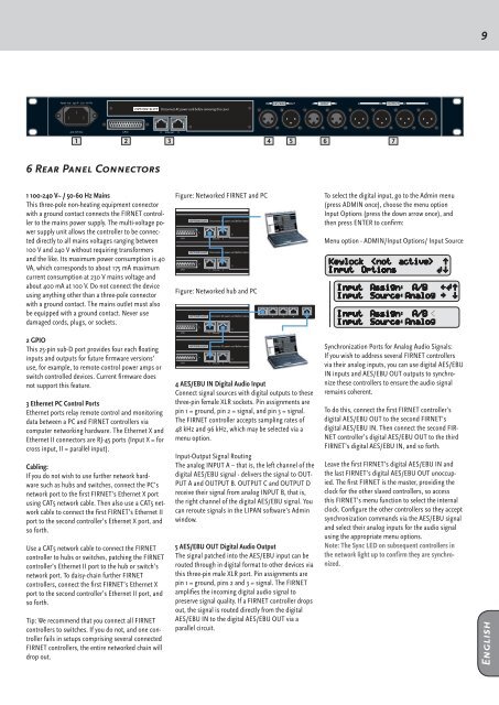
6 Rear Panel Connectors<br />
1 100-240 V~ / 50-60 Hz Mains<br />
This three-pole non-heating equipment connector<br />
with a g<strong>ro</strong>und contact connects the FIRNET cont<strong>ro</strong>ller<br />
to the mains power supply. The multi-voltage power<br />
supply unit allows the cont<strong>ro</strong>ller to be connected<br />
directly to all mains voltages ranging between<br />
100 V and 240 V without requiring transformers<br />
and the like. Its maximum power consumption is 40<br />
VA, which corresponds to about 175 mA maximum<br />
current consumption at 230 V mains voltage and<br />
about 400 mA at 100 V. Do not connect the device<br />
using anything other than a three-pole connector<br />
with a g<strong>ro</strong>und contact. The mains outlet must also<br />
be equipped with a g<strong>ro</strong>und contact. Never use<br />
damaged cords, plugs, or sockets.<br />
Figure: Networked FIRNET and PC<br />
Figure: Networked hub and PC<br />
To select the digital input, go to the Admin menu<br />
(press ADMIN once), choose the menu option<br />
Input Options (press the down ar<strong>ro</strong>w once), and<br />
then press ENTER to confirm:<br />
Menu option - ADMIN/Input Options/ Input Source<br />
2 GPIO<br />
This 25-pin sub-D port p<strong>ro</strong>vides four each floating<br />
inputs and outputs for future firmware versions’<br />
use, for example, to remote-cont<strong>ro</strong>l power amps or<br />
switch cont<strong>ro</strong>lled devices. Current firmware does<br />
not support this feature.<br />
3 Ethernet PC Cont<strong>ro</strong>l Ports<br />
Ethernet ports relay remote cont<strong>ro</strong>l and monitoring<br />
data between a PC and FIRNET cont<strong>ro</strong>llers via<br />
computer networking hardware. The Ethernet X and<br />
Ethernet II connectors are RJ-45 ports (Input X = for<br />
c<strong>ro</strong>ss input, II = parallel input).<br />
Cabling:<br />
If you do not wish to use further network hardware<br />
such as hubs and switches, connect the PC’s<br />
network port to the first FIRNET’s Ethernet X port<br />
using CAT5 network cable. Then also use a CAT5 network<br />
cable to connect the first FIRNET’s Ethernet II<br />
port to the second cont<strong>ro</strong>ller’s Ethernet X port, and<br />
so forth.<br />
Use a CAT5 network cable to connect the FIRNET<br />
cont<strong>ro</strong>ller to hubs or switches, patching the FIRNET<br />
cont<strong>ro</strong>ller’s Ethernet II port to the hub or switch’s<br />
network port. To daisy-chain further FIRNET<br />
cont<strong>ro</strong>llers, connect the first FIRNET’s Ethernet X<br />
port to the second cont<strong>ro</strong>ller’s Ethernet II port, and<br />
so forth.<br />
Tip: We recommend that you connect all FIRNET<br />
cont<strong>ro</strong>llers to switches. If you do not, and one cont<strong>ro</strong>ller<br />
fails in setups comprising several connected<br />
FIRNET cont<strong>ro</strong>llers, the entire networked chain will<br />
d<strong>ro</strong>p out.<br />
4 AES/EBU IN Digital Audio Input<br />
Connect signal sources with digital outputs to these<br />
three-pin female XLR sockets. Pin assignments are<br />
pin 1 = g<strong>ro</strong>und, pin 2 = signal, and pin 3 = signal.<br />
The FIRNET cont<strong>ro</strong>ller accepts sampling rates of<br />
48 kHz and 96 kHz, which may be selected via a<br />
menu option.<br />
Input-Output Signal Routing<br />
The analog INPUT A – that is, the left channel of the<br />
digital AES/EBU signal - delivers the signal to OUT-<br />
PUT A and OUTPUT B. OUTPUT C and OUTPUT D<br />
receive their signal f<strong>ro</strong>m analog INPUT B, that is,<br />
the right channel of the digital AES/EBU signal. You<br />
can re<strong>ro</strong>ute signals in the LIPAN software’s Admin<br />
window.<br />
5 AES/EBU OUT Digital Audio Output<br />
The signal patched into the AES/EBU input can be<br />
<strong>ro</strong>uted th<strong>ro</strong>ugh in digital format to other devices via<br />
this three-pin male XLR port. Pin assignments are<br />
pin 1 = g<strong>ro</strong>und, pins 2 and 3 = signal. The FIRNET<br />
amplifies the incoming digital audio signal to<br />
preserve signal quality. If a FIRNET cont<strong>ro</strong>ller d<strong>ro</strong>ps<br />
out, the signal is <strong>ro</strong>uted directly f<strong>ro</strong>m the digital<br />
AES/EBU IN to the digital AES/EBU OUT via a<br />
parallel circuit.<br />
Synch<strong>ro</strong>nization Ports for Analog Audio Signals:<br />
If you wish to address several FIRNET cont<strong>ro</strong>llers<br />
via their analog inputs, you can use digital AES/EBU<br />
IN inputs and AES/EBU OUT outputs to synch<strong>ro</strong>nize<br />
these cont<strong>ro</strong>llers to ensure the audio signal<br />
remains coherent.<br />
To do this, connect the first FIRNET cont<strong>ro</strong>ller’s<br />
digital AES/EBU OUT to the second FIRNET’s<br />
digital AES/EBU IN. Then connect the second FIR-<br />
NET cont<strong>ro</strong>ller’s digital AES/EBU OUT to the third<br />
FIRNET’s digital AES/EBU IN, and so forth.<br />
Leave the first FIRNET’s digital AES/EBU IN and<br />
the last FIRNET’s digital AES/EBU OUT unoccupied.<br />
The first FIRNET is the master, p<strong>ro</strong>viding the<br />
clock for the other slaved cont<strong>ro</strong>llers, so access<br />
this FIRNET’s menu function to select the internal<br />
clock. Configure the other cont<strong>ro</strong>llers so they accept<br />
synch<strong>ro</strong>nization commands via the AES/EBU signal<br />
and select their analog inputs for the audio signal<br />
using the app<strong>ro</strong>priate menu options.<br />
Note: The Sync LED on subsequent cont<strong>ro</strong>llers in<br />
the network light up to confirm they are synch<strong>ro</strong>nized.<br />
English