OMF098J10B OMV098J12B - Wolseley Canada Inc
OMF098J10B OMV098J12B - Wolseley Canada Inc
OMF098J10B OMV098J12B - Wolseley Canada Inc

You also want an ePaper? Increase the reach of your titles
YUMPU automatically turns print PDFs into web optimized ePapers that Google loves.
2 INSTALLATION<br />
This furnace is a true multi-position unit, in that it will<br />
function in an upflow, downflow or horizontal configuration<br />
to the left or the right. Only a few modifications are<br />
required during installation to change from one position to<br />
another. The unit is shipped in the upflow configuration<br />
and instructions as to how to change to the other<br />
positions are included in this manual.<br />
The unit is shipped with a burner and its controls. It<br />
requires a 115VAC power supply to the control panel and<br />
thermostat hook-up as shown on the wiring diagram, one<br />
or more oil line connections, suitable ductwork and<br />
connection to a properly sized vent.<br />
All local and national code requirements governing the<br />
installation of oil burning equipment, wiring and the flue<br />
connection MUST be followed. Some of the codes that<br />
may apply are:<br />
CSA B139: Installation code for oil burning<br />
equipment.<br />
ANSI/NFPA 31: Installation of oil burning equipment.<br />
ANSI/NFPA 90B: Warm air heating and air conditioning<br />
systems.<br />
ANSI/NFPA 211: Chimneys, Fireplaces, Vents and solid<br />
fuel burning appliances.<br />
ANSI/NFPA 70: National Electrical Code.<br />
CSA C22.1 or CSA C22.10:<br />
Canadian Electrical Code.<br />
Only the latest issues of these codes may be used.<br />
The unit must be installed in an area where the ambient<br />
and return air temperatures are above 15°C (60°F). In<br />
addition, the furnace should be installed as closely as<br />
possible to the vent, so that the connections are direct<br />
and kept to a minimum. The heater should also be<br />
located close to the centre of the air distribution system.<br />
2.1.1 Installation in an enclosure<br />
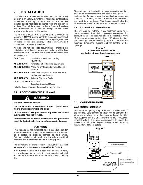
The unit can be installed in an enclosure such as a<br />
closet. However, 2 ventilation openings are required for<br />
combustion air. The openings should be located in front<br />
of the furnace approximately 15 cm (6") above the floor<br />
and 15 cm (6") below the ceiling. Figure 1 indicates the<br />
minimum dimensions required and the location of the<br />
openings.<br />
Figure 1<br />
Location and dimensions of<br />
ventilation air openings in a closet door<br />
2.1 POSITIONING THE FURNACE<br />
WARNING<br />
Fire and explosion hazard.<br />
The furnace must be installed in a level position, never<br />
where it will slope toward the front.<br />
Do not store or use gasoline or any other flammable<br />
substances near the furnace.<br />
Non-observance of these instructions will potentially<br />
result in death, bodily injury and/or property damage.<br />
CAUTION<br />
This furnace is not watertight and is not designed for<br />
outdoor installation. It must be installed in such a manner<br />
as to protect its electrical components from water.<br />
Outdoor installation will lead to a hazardous electrical<br />
condition and to premature failure of the equipment.<br />
The minimum clearances from combustible material<br />
for each of the positions are specified in Table 4.<br />
If the furnace is installed in a basement or on a dirt floor,<br />
in a crawl space for example, it is recommended to install<br />
the unit on a cement base 2.5 cm to 5.0 cm (1" to 2")<br />
thick.<br />
2.2 CONFIGURATIONS<br />
2.2.1 Upflow Installation<br />
The return air opening may be located on either side of<br />
the furnace. Care should be taken not to damage the<br />
wires inside, while cutting the opening. Install the filter<br />
rack supplied with the unit according to the instructions<br />
provided with it. It is also recommended to install the<br />
blower door before handling or moving the unit. Refer to<br />
Figure 2 for additional details.<br />
Figure 2<br />
Burner position<br />
Filter 20" x 20"<br />
Combustible or<br />
non-combustible<br />
floor<br />
4