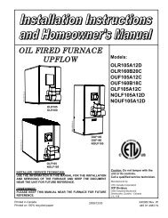
OMF098J10B OMV098J12B - Wolseley Canada Inc
OMF098J10B OMV098J12B - Wolseley Canada Inc
OMF098J10B OMV098J12B - Wolseley Canada Inc

Create successful ePaper yourself
Turn your PDF publications into a flip-book with our unique Google optimized e-Paper software.
g. Halogen type refrigerants;<br />
h. Cleaning solvents (such as perchloroethylene);<br />
i. Printing inks, paint removers, varnishes, etc. ;<br />
j. Hydrochloric acid;<br />
k. Solvent based glue;<br />
l. Antistatic fabric softeners for clothes dryers;<br />
m. Acid based masonry cleaning materials.<br />
2.8.2 Burner with Outdoor Combustion Air Kit<br />
Certain burners are designed to function with combustion air<br />
taken directly from the outside. Follow the instructions provided<br />
with the burner, the fresh-air supply kit or the side-wall venting<br />
kit.<br />
2.9 OIL TANK<br />
WARNING<br />
Fire and explosion hazard.<br />
Use only approved heating type oil in this furnace.<br />
DO NOT USE waste oil, used motor oil, gasoline or<br />
kerosene.<br />
Use of these will result in death, bodily injury and/or<br />
property damage.<br />
CAUTION<br />
When a 0.75 USGPH or smaller nozzle is used, a 10 micron or<br />
finer filter, must be installed on the oil supply line to the<br />
furnace inside the building where the unit is located.<br />
This is a requirement in order for the heat exchanger warranty<br />
to remain in force.<br />
Check your local codes for the installation of the oil tank and<br />
accessories.<br />
At the beginning of each heating season or once a year, check<br />
the complete oil distribution system for leaks.<br />
Ensure that the tank is full of clean oil. Use No.1 or No.2<br />
Heating Oil (ASTM D396 U.S.) or in <strong>Canada</strong>, use No.1 or No.2<br />
Furnace Oil.<br />
A manual shut-off valve and an oil filter shall be installed in<br />
sequence from tank to burner. Be sure that the oil line is clean<br />
before connecting to the burner. The oil line should be<br />
protected to eliminate any possible damage. Installations<br />
where the oil tank is below the burner level must employ a twopipe<br />
fuel supply system with an appropriate fuel pump. A rise<br />
of 2.4 m (8') and more requires a two stage pump and a rise<br />
greater than 4.9 m (16') an auxiliary pump. Follow the pump<br />
instructions to determine the size of pipe needed in relation to<br />
the rise or to the horizontal distance.<br />
2.10 DUCTING<br />
WARNING<br />
Poisonous carbon monoxide gas hazard.<br />
DO NOT draw return air from inside a closet or utility<br />
room. Return air MUST be sealed to the furnace<br />
casing.<br />
Failure to properly seal ducts can result in death,<br />
bodily injury and/or property damage.<br />
The ducting must be designed and installed according to<br />
approved methods, local and national codes as well as<br />
good trade practices.<br />
When ducting supplies air to a space other than where the<br />
furnace is located, the return air must be sealed and also<br />
be directed to the space other than where the furnace is<br />
located.<br />
2.10.1 Air filter<br />
A properly sized air filter must be installed on the return air<br />
side of the unit. Refer to the Technical Specifications,<br />
p.15, for the correct dimensions. Also refer to Section 2.2<br />
and the instructions supplied with the filter.<br />
2.11 SUPPLY AIR ADJUSTMENTS<br />
(4 SPEED MOTORS)<br />
On units equipped with 4-speed blower motors, the supply<br />
air must be adjusted based on heating/air conditioning<br />
output and the static pressure of the duct system. For the<br />
desired air flow refer to the following table as well as the<br />
air flow tables based on static pressure in the Technical<br />
Specifications section of this manual.<br />
FURNACE<br />
APPLICATION<br />
HEATING<br />
A/C<br />
BLOWER SPEED ADJUSTMENTS<br />
(4 SPEED MOTORS)<br />
HEATING OR A/C<br />
OUTPUT<br />
RECOMMENDED<br />
BLOWER SPEED<br />
0.50 USGPH MED-LOW<br />
0.60 USGPH MED-HIGH<br />
0.70 USGPH HIGH<br />
2.0 TONS MED-LOW<br />
2.5 TONS MED-HIGH<br />
3.0 TONS HIGH<br />
To effect the adjustment, the RED (for heating) and BLUE<br />
(for cooling and heat pump) wires can be changed on the<br />
motor. Also, refer to the position of the wires on the<br />
electronic board of the unit and consult the wiring<br />
diagrams. If the heating and air conditioning speeds are<br />
the same, the RED wire must be moved to “UNUSED<br />
LEADS” on the electronic board and the jumper provided<br />
with the BLUE wire must be used between the “HEAT”<br />
and “COOL” terminals.<br />
The blower start/stop delays can be adjusted by<br />
positioning the DIP switches on the electronic board as<br />
shown in the following figures. The recommended blower<br />
ON delay is 60 seconds and the blower OFF delay is 2<br />
minutes.<br />
8