OMF098J10B OMV098J12B - Wolseley Canada Inc
OMF098J10B OMV098J12B - Wolseley Canada Inc
OMF098J10B OMV098J12B - Wolseley Canada Inc

You also want an ePaper? Increase the reach of your titles
YUMPU automatically turns print PDFs into web optimized ePapers that Google loves.
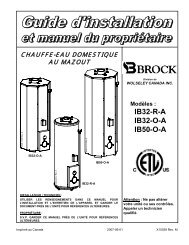
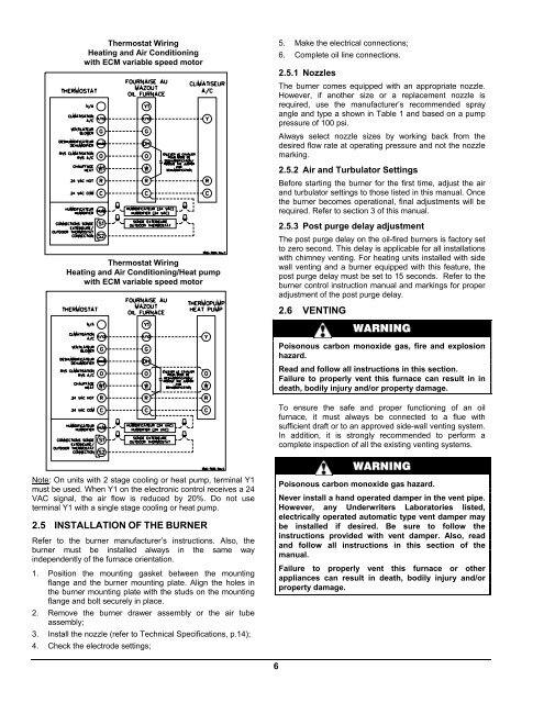
Thermostat Wiring<br />
Heating and Air Conditioning<br />
with ECM variable speed motor<br />
5. Make the electrical connections;<br />
6. Complete oil line connections.<br />
2.5.1 Nozzles<br />
The burner comes equipped with an appropriate nozzle.<br />
However, if another size or a replacement nozzle is<br />
required, use the manufacturer’s recommended spray<br />
angle and type a shown in Table 1 and based on a pump<br />
pressure of 100 psi.<br />
Always select nozzle sizes by working back from the<br />
desired flow rate at operating pressure and not the nozzle<br />
marking.<br />
2.5.2 Air and Turbulator Settings<br />
Before starting the burner for the first time, adjust the air<br />
and turbulator settings to those listed in this manual. Once<br />
the burner becomes operational, final adjustments will be<br />
required. Refer to section 3 of this manual.<br />
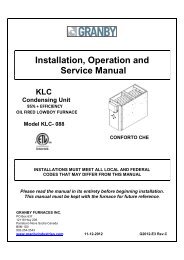
Thermostat Wiring<br />
Heating and Air Conditioning/Heat pump<br />
with ECM variable speed motor<br />
2.5.3 Post purge delay adjustment<br />
The post purge delay on the oil-fired burners is factory set<br />
to zero second. This delay is applicable for all installations<br />
with chimney venting. For heating units installed with side<br />
wall venting and a burner equipped with this feature, the<br />
post purge delay must be set to 15 seconds. Refer to the<br />
burner control instruction manual and markings for proper<br />
adjustment of the post purge delay.<br />
2.6 VENTING<br />
WARNING<br />
Poisonous carbon monoxide gas, fire and explosion<br />
hazard.<br />
Read and follow all instructions in this section.<br />
Failure to properly vent this furnace can result in in<br />
death, bodily injury and/or property damage.<br />
To ensure the safe and proper functioning of an oil<br />
furnace, it must always be connected to a flue with<br />
sufficient draft or to an approved side-wall venting system.<br />
In addition, it is strongly recommended to perform a<br />
complete inspection of all the existing venting systems.<br />
Note: On units with 2 stage cooling or heat pump, terminal Y1<br />
must be used. When Y1 on the electronic control receives a 24<br />
VAC signal, the air flow is reduced by 20%. Do not use<br />
terminal Y1 with a single stage cooling or heat pump.<br />
2.5 INSTALLATION OF THE BURNER<br />
Refer to the burner manufacturer’s instructions. Also, the<br />
burner must be installed always in the same way<br />
independently of the furnace orientation.<br />
1. Position the mounting gasket between the mounting<br />
flange and the burner mounting plate. Align the holes in<br />
the burner mounting plate with the studs on the mounting<br />
flange and bolt securely in place.<br />
2. Remove the burner drawer assembly or the air tube<br />
assembly;<br />
3. Install the nozzle (refer to Technical Specifications, p.14);<br />
4. Check the electrode settings;<br />
WARNING<br />
Poisonous carbon monoxide gas hazard.<br />
Never install a hand operated damper in the vent pipe.<br />
However, any Underwriters Laboratories listed,<br />
electrically operated automatic type vent damper may<br />
be installed if desired. Be sure to follow the<br />
instructions provided with vent damper. Also, read<br />
and follow all instructions in this section of the<br />
manual.<br />
Failure to properly vent this furnace or other<br />
appliances can result in death, bodily injury and/or<br />
property damage.<br />
6