Daker DK 1, 2, 3 kVA - Conventional UPS systems - Legrand
Daker DK 1, 2, 3 kVA - Conventional UPS systems - Legrand
Daker DK 1, 2, 3 kVA - Conventional UPS systems - Legrand

You also want an ePaper? Increase the reach of your titles
YUMPU automatically turns print PDFs into web optimized ePapers that Google loves.
®<br />
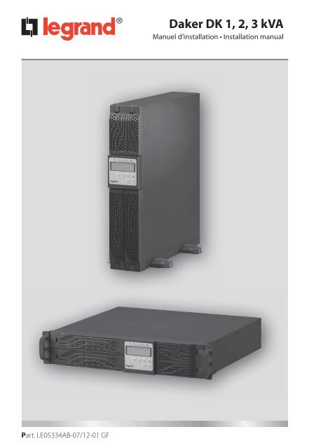
<strong>Daker</strong> <strong>DK</strong> 1, 2, 3 <strong>kVA</strong><br />
Manuel d’installation • Installation manual<br />
Part. LE05334AB-07/12-01 GF
®<br />
<strong>Daker</strong> <strong>DK</strong> 1, 2, 3 <strong>kVA</strong><br />
FR<br />
FRANÇAIS 3<br />
UK FR<br />
ENGLISH 21<br />
IT<br />
ITALIANO 23<br />
DE<br />
DEUTSCH 33<br />
ES<br />
ESPAÑOL 43<br />
2
<strong>Daker</strong> <strong>DK</strong> 1, 2, 3 <strong>kVA</strong><br />
Indice<br />
FR<br />
1 Introduction 4<br />
2 Conditions d’utilisation 4<br />
3 Panneau LCD 5<br />
4 Installation 8<br />
5 Logiciel d’autodiagnostic ups communicator 14<br />
6 Changement batteries 15<br />
7 Dysfonctionnements possibles 17<br />
8 Caractéristiques techniques 18<br />
3
®<br />
1 Introduction<br />
Ce manuel contient les informations concernant l’utilisation des modèles <strong>Daker</strong> <strong>DK</strong> 1, 2, 3 <strong>kVA</strong>.<br />
Il est recommandé de lire attentivement ce manuel avant de procéder à l’installation de l’onduleur<br />
et de respecter scrupuleusement les instructions ci-dessous.<br />
Les <strong>UPS</strong> <strong>Daker</strong> <strong>DK</strong> 1, 2, 3 <strong>kVA</strong> sont conçus pour une utilisation civile ou industrielle.<br />
Ils ne sont pas conformes aux réglementations pour appareils électriques médicaux.<br />
En cas de problème sur l’<strong>UPS</strong>, il est recommandé de lire le présent manuel avant de contacter le<br />
service d’assistance technique ; la section “Éventuels problèmes et solutions” permet en effet de<br />
résoudre la plupart des problèmes rencontrés durant l’utilisation du groupe de continuité.<br />
2 Conditions d’utilisation<br />
• L’<strong>UPS</strong> est conçu pour alimenter des appareillages de traitement de données ; la charge appliquée<br />
ne doit pas dépasser celle indiquée sur l’étiquette apposée au dos de l’<strong>UPS</strong>.<br />
• Le bouton ON/OFF de l’<strong>UPS</strong> n’isole pas électriquement les parties internes. Pour isoler l’<strong>UPS</strong>, le<br />
débrancher de la prise d’alimentation du secteur.<br />
• Ne pas ouvrir le conteneur de l’<strong>UPS</strong> car des parties peuvent être sous tension dangereuse à l’intérieur,<br />
même si la prise du secteur est débranchée. Dans tous les cas, à l’intérieur de l’onduleur,<br />
aucune pièce ne peut être réparée par l’utilisateur.<br />
• Le panneau frontal de contrôle est prévu pour des opérations manuelles ; ne pas appuyer sur le<br />
panneau avec des objets pointus ou coupants.<br />
• Les <strong>UPS</strong> <strong>Daker</strong> <strong>DK</strong> ont été conçus pour fonctionner dans un environnement fermé, propre, sans<br />
liquide inflammable ou substances corrosives et non excessivement humide.<br />
• Ne pas positionner l’onduleur à proximité d’appareils qui génèrent de forts champs électromagnétiques<br />
et/ou d’appareils sensibles aux champs électromagnétiques (moteurs, disquettes,<br />
haut-parleurs, transformateurs, écrans, video, etc...).<br />
• Ne pas verser de liquides sur ou dans l’<strong>UPS</strong>.<br />
• Éviter d’exposer l’<strong>UPS</strong> à la lumière directe du soleil ou à proximité de sources de chaleur.<br />
• Maintenir toujours propres les fentes d’aération et ne pas les obstruer afin de permettre la dissipation<br />
de la chaleur interne de l’<strong>UPS</strong>.<br />
• Brancher l’<strong>UPS</strong> à une installation équipée d’un conducteur de mise à la terre.<br />
• Ne pas utiliser l’<strong>UPS</strong> pour alimenter des imprimantes laser à cause de leur courant de démarrage<br />
élevé.<br />
• Ne pas utiliser l’<strong>UPS</strong> pour alimenter des électroménagers comme les sèche-cheveux, les climatiseurs,<br />
les réfrigérateurs, etc.<br />
4
<strong>Daker</strong> <strong>DK</strong> 1, 2, 3 <strong>kVA</strong><br />
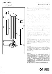
3 Panneau LCD<br />
FR<br />
1<br />
2 3 4 5 6<br />
7 8 9 10 11 12<br />
1. Panneau LCD.<br />
2. Le LED vert allumé indique que l’alimentation sur secteur est comprise entre 160 et 288 Vca.<br />
3-4. Les leds verts indiquent que sont présentes les sorties programmables Outlet 1 et Outlet 2.<br />
5. Le LED orange indique que le By-pass est actif.<br />
6. LED d’alarme <strong>UPS</strong>.<br />
7. Bouton d’allumage <strong>UPS</strong>/Désactivation avertisseur sonore.<br />
8. Bouton d’extinction <strong>UPS</strong>.<br />
9. Bouton menu d’accès aux fonctions spéciales, log in/out.<br />
10. Bouton de sélection de la page suivante.<br />
11. Bouton de sélection de la page précédente ou de changement réglage.<br />
12. Bouton de confirmation de sélection.<br />
5
®<br />
3 Panneau LCD<br />
Symboles écran LCD<br />
Réf. Symbole Description<br />
LINE<br />
1 Alimentation sur secteur<br />
2 Niveau batterie fiable<br />
3 Batterie endommagée<br />
4 Surcharge<br />
5 Erreur de branchement terre<br />
6 Fonctionnement en Service Mode<br />
OFF<br />
7 <strong>UPS</strong> éteint<br />
FAIL<br />
8 <strong>UPS</strong> en alarme<br />
9 Schéma de fonctionnement <strong>UPS</strong><br />
10 Visualisation mesures<br />
11 Indique le paramètre mesuré<br />
Er05<br />
22 Batterie faible ou à changer<br />
Er06<br />
23 Court-circuit en sortie<br />
Er10<br />
24 Courant excessif variateur fréquence<br />
Er11<br />
25 Surchauffe<br />
Er12<br />
26 Surcharge en sortie<br />
Er**<br />
27 Autres alarmes<br />
6
<strong>Daker</strong> <strong>DK</strong> 1, 2, 3 <strong>kVA</strong><br />
FR<br />
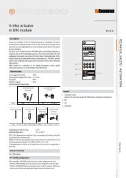
Panneau arrière 230V<br />
17 18<br />
16<br />
13<br />
1<br />
14<br />
+<br />
G<br />
-<br />
INTERFACE<br />
AC OUTPUT<br />
3 100 50<br />
AC INPUT<br />
15<br />
EPO<br />
G<br />
DC 36V<br />
INPUT<br />
BREAKER<br />
2<br />
22<br />
21<br />
20<br />
19<br />
17 21 18<br />
16<br />
13<br />
14<br />
+ G<br />
-<br />
G<br />
1 2<br />
INPUT<br />
BREAKER<br />
AC INPUT<br />
INTERFACE<br />
3 100 51<br />
15<br />
EPO<br />
DC 72V<br />
AC OUTPUT<br />
22<br />
20<br />
19<br />
17 24 23 21 18<br />
16<br />
13<br />
14<br />
+ G<br />
-<br />
G<br />
OUTPUT BREAKER<br />
1/2<br />
1 2 A<br />
INPUT<br />
BREAKER<br />
B<br />
AC INPUT<br />
INTERFACE<br />
3 100 52<br />
15<br />
EPO<br />
DC 72V<br />
AC OUTPUT<br />
22<br />
20<br />
19<br />
13. Port de communication USB<br />
14. Port de communication RS232<br />
15. Coupure d’urgence alimentation (EPO)<br />
16. Logement pour cartes de communication<br />
en option<br />
17. Connecteur expansion autonomie<br />
18. Connexions d’entrée<br />
19. Connexions de sortie<br />
20. Sorties programmables<br />
21. Interrupteurs de protection d’entrée<br />
22. Ventilateurs de refroidissement<br />
23. Interrupteurs de protection de sortie<br />
24. Interrupteurs de protection des sorties<br />
programmables<br />
7
®<br />
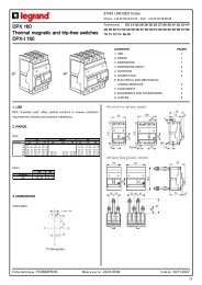
4 Installation<br />
Contrôler le contenu de l’emballage :<br />
• Mode d’emploi<br />
• Câble de branchement charges sortie<br />
• Câble d’entrée<br />
• Câble de communication RS232<br />
• Câble de communication USB<br />
• Accessoires de configuration Tower/rack<br />
A3 - Optional<br />
1 pcs<br />
A1<br />
A2 - Optional<br />
A4<br />
4 pcs 1 pcs 1 pcs<br />
B1<br />
B2<br />
2 pcs 2 pcs<br />
S1<br />
S2<br />
S3<br />
6.0<br />
±1.0mm<br />
M3<br />
2 pcs<br />
6.0<br />
±1.0mm<br />
M3<br />
16 pcs<br />
8.0<br />
±1.0mm<br />
M4<br />
6 pcs<br />
8
<strong>Daker</strong> <strong>DK</strong> 1, 2, 3 <strong>kVA</strong><br />
FR<br />
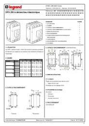
Configuration tower<br />
Step 1<br />
A1<br />
A1<br />
A1<br />
A1<br />
Step 2<br />
A3<br />
A2<br />
9
®<br />
4 Installation<br />
<strong>UPS</strong> + armoire batterie (option)<br />
Step 1<br />
Step 2<br />
A4<br />
10
<strong>Daker</strong> <strong>DK</strong> 1, 2, 3 <strong>kVA</strong><br />
FR<br />
Configuration rack 19”<br />
Step 1<br />
Step 2<br />
B1<br />
S3<br />
B2<br />
Step 3<br />
90°<br />
Step 4<br />
11
®<br />
4 Installation<br />
Step 5<br />
Step 6<br />
12
<strong>Daker</strong> <strong>DK</strong> 1, 2, 3 <strong>kVA</strong><br />
FR<br />
Au dos du groupe de continuité sont prévus les branchements suivants :<br />
• Prises de sortie [19] et connecteur d’entrée [18] : à ces deux connecteurs, brancher le câble<br />
d’alimentation et les câbles de sortie fournis à cet effet.<br />
• Prise de branchement interface sérielle de l’ordinateur type RS232 (9 pôles femelle) [4] : à utiliser<br />
dans le cas où l’on souhaiterait utiliser le logiciel de diagnostic et gestion extinction.<br />
• Prise de branchement interface USB [13] : à utiliser dans le cas où l’on souhaiterait connecter<br />
l’<strong>UPS</strong> par l’intermédiaire du câble USB.<br />
• Connexion prévue pour batteries supplémentaires [17].<br />
AVERTISSEMENT<br />
Pour des raisons de sécurité, il est recommandé de ne pas modifier les câbles fournis ; en<br />
outre, il est nécessaire de s’assurer que le prise de secteur à laquelle le groupe de continuité<br />
est branché dispose d'une bonne connexion au circuit de terre comme requis par la norme.<br />
AVERTISSEMENT<br />
La prise d’alimentation sur secteur ou le dispositif de sectionnement doit être installé à<br />
proximité de l’appareillage et doit être facile d’accès.<br />
Procéder à l’installation comme suit :<br />
1) Positionner le groupe de continuité de telle sorte que les fentes de ventilation ne soient pas<br />
obstruées.<br />
2) Au connecteur d’entrée [18], brancher le câble d’alimentation et les câbles de sortie aux<br />
connecteurs correspondants [19].<br />
3) Brancher les charges aux câbles de sortie en s’assurant que les interrupteurs des différents<br />
dispositifs sont sur la position Off.<br />
4) Brancher la fiche d’alimentation à une prise de courant adaptée à la tension et au courant<br />
requis.<br />
Allumage<br />
1) Allumer le groupe de continuité à l’aide du bouton prévu à cet effet [7] en le maintenant<br />
enfoncé pendant 3 secondes environ jusqu’à ce que l’<strong>UPS</strong> émette un signal sonore ; ensuite, les<br />
leds LINE, , et s’allument au bout de 30 secondes environ.<br />
2) Allumer les charges et s'assurer de l'absence de signaux d'alarme.<br />
3) Il est recommandé d’effectuer une commutation sur batteries, en coupant l'alimentation<br />
sur secteur, avant de brancher les charges critiques à l’<strong>UPS</strong> pour s’assurer que les batteries<br />
fonctionnent correctement.<br />
Extinction<br />
1) Appuyer OFF sur le bouton d’extinction [8] en le maintenant enfoncé pendant 5 secondes environ<br />
FAIL<br />
jusqu’à ce que l’<strong>UPS</strong> émette un signal sonore. L'<strong>UPS</strong> coupe l’alimentation sur les connecteurs<br />
de sortie. Tous les LEDs s’éteignent mais les ventilateurs continuent à fonctionner tant que<br />
l’alimentation sur secteur est présente.<br />
Er05<br />
Er06<br />
Er10<br />
13
®<br />
4 Installation<br />
Fonctions spéciales<br />
L'<strong>UPS</strong> est doté de deux sorties programmables pour les charges les moins critiques. Ces prises<br />
peuvent être désactivées ou temporisées durant le fonctionnement sur batteries, pour maintenir<br />
une alimentation de qualité pour les charges les plus critiques.<br />
Il est possible d’accéder à cette fonction et à d’autres fonctions en téléchargeant gratuitement le<br />
logiciel “<strong>UPS</strong> Setting tool” sur le site www.ups.legrand.com.<br />
Connexion<br />
L’<strong>UPS</strong> est doté d’interfaces standard RS232 et USB grâce auxquelles il est possible d'accéder, par<br />
l’intermédiaire d’un ordinateur, à une série de données relatives au fonctionnement et à l’historique<br />
de l’<strong>UPS</strong>. La fonction est utilisable par l’intermédiaire du programme d’interface pour WINDOWS (*),<br />
en connectant un port sériel du PC aux prises d’interface [Indicare numero riferimento] présent au<br />
dos de l’<strong>UPS</strong>, à l’aide d’un câble RS 232 ou USB.<br />
5 Logiciel d’autodiagnostic ups communicator<br />
Sur le site www.ups.legrand.com, il est possible de télécharger gratuitement un logiciel d’autodiagnostic<br />
pour WINDOWS (16 et 32 bits) et Linux.<br />
Ce logiciel fournit les fonctions suivantes :<br />
- Visualisation de toutes les données de fonctionnement et de diagnostic en cas de problème.<br />
- Configuration des fonctions spéciales.<br />
- Extinction automatique de l’ordinateur local (avec logiciel d’exploitation Windows et Linux).<br />
* Windows est une marque enregistrée de Microsoft Corporation.<br />
14
<strong>Daker</strong> <strong>DK</strong> 1, 2, 3 <strong>kVA</strong><br />
6 Changement batteries<br />
FR<br />
Step 1<br />
Step 2<br />
15
®<br />
6 Changement batteries<br />
Step 3<br />
Step 4<br />
3 100 50<br />
Step 4<br />
3 100 51<br />
3 100 52<br />
16
<strong>Daker</strong> <strong>DK</strong> 1, 2, 3 <strong>kVA</strong><br />
7 Dysfonctionnements possibles<br />
FR<br />
L’<strong>UPS</strong> marche toujours avec alimentation batterie :<br />
• la tension de secteur n’est pas présente ;<br />
• la tension de secteur est hors des limites de la plage de l’<strong>UPS</strong> ;<br />
• le câble d’alimentation n’est pas correctement branché à la prise d’alimentation.<br />
• l’interrupteur magnétothermique est en position relevée.<br />
• la prise d’alimentation est défectueuse.<br />
L’<strong>UPS</strong> signale une surcharge :<br />
• des charges supplémentaires, en plus de celles normalement connectées, ont été involontairement<br />
branchées ;<br />
• vérifier toutes les charges branchées en sortie.<br />
L’<strong>UPS</strong> ne fonctionne pas avec alimentation batterie (il se bloque ou signale immédiatement une<br />
réserve autonomie):<br />
• l’<strong>UPS</strong> a marché pendant longtemps sans alimentation de secteur et n’a pas pu recharger sa<br />
batterie. La recharger pendant au moins 6 heures en branchant l’onduleur à l’alimentation<br />
secteur, allumé.<br />
• la batterie est déchargée à cause d’une longue période d’inactivité de l’<strong>UPS</strong>. La recharger<br />
pendant au moins 6 heures en branchant l’onduleur à l’alimentation secteur.<br />
• la batterie s’est épuisée à cause de son utilisation fréquente, des conditions environnementales<br />
ou du dépassement de la durée moyenne de vie, elle doit être remplacée.<br />
L’<strong>UPS</strong> ne fournit pas de tension en sortie:<br />
• vérifier que les charges sont correctement branchées aux prises de sortie.<br />
17
®<br />
8 Caractéristiques techniques<br />
SPÉCIFICATIONS DE CONSTRUCTION 3 100 50 3 100 51 3 100 52<br />
Poids 16 Kg 29,5 Kg 30 Kg<br />
Dimensions L x H x P en millimètres 440 x 88 x 412 440 x 88 x 658 440 x 88 x 658<br />
Protections électroniques<br />
Contre les surcharges et les courts-circuits<br />
Blocage du fonctionnement dû à la fin<br />
d’autonomie et à la surchauffe<br />
Extinction automatique due à l’activation<br />
des protections<br />
Spécifications environnementales<br />
Température de fonctionnement de 0 à +40 °C<br />
Humidité relative pour le fonctionnement<br />
de 20 à 80% sans condensation<br />
Niveau de protection suivant IEC529<br />
IP20<br />
Niveau de bruit à 1 mètre<br />
< 50 dBA<br />
Caractéristiques électriques d’entrée<br />
Tension nominale d’entrée<br />
230 V<br />
Tension d’entrée<br />
de 160 V à 288 V<br />
Fréquence nominale d’entrée 50 ou 60 Hz ± 5%<br />
Courant maximum d’entrée 5,2 Arms 10,4 Arms 15 Arms<br />
Nombre des phases d’entrée<br />
monophasé<br />
Forme d’onde de sortie<br />
Avec fonctionnement batterie<br />
sinusoïdale<br />
Type de fonctionnement<br />
on line - conversion double<br />
Caractéristiques électriques de sortie avec alimentation secteur<br />
Tension nominale de sortie 230 V ± 1%<br />
Puissance active de sortie avec charge nominale 800W 1,6 kW 2,4 kW<br />
Puissance apparente de sortie<br />
avec charge nominale<br />
1<strong>kVA</strong> 2 KWA 3 KWA<br />
105% sans interruption<br />
Capacité de surcharge<br />
120% pendant 30 secondes<br />
150% pendant 10 secondes<br />
Nombre des phases de sortie<br />
monophasé<br />
18
<strong>Daker</strong> <strong>DK</strong> 1, 2, 3 <strong>kVA</strong><br />
FR<br />
SPÉCIFICATIONS DE CONSTRUCTION 3 100 50 3 100 51 3 100 52<br />
Caractéristiques électriques de sortie avec alimentation<br />
Tension nominale de sortie 230 V ± 1%<br />
Fréquence de sortie 50/60 Hz ± 5%<br />
Puissance active de sortie<br />
sur charge non linéaire<br />
800W 1,6kW 2,4kW<br />
Puissance apparente de sortie<br />
sur charge non linéaire<br />
1<strong>kVA</strong> 2<strong>kVA</strong> 3<strong>kVA</strong><br />
Fonctionnement avec batterie<br />
Autonomie à 80% de la charge<br />
8 min.<br />
Temps de recharge<br />
4-6 heures à 80% de la charge<br />
Données techniques et quantité de batteries<br />
Normes<br />
Compatibilité électromagnétique<br />
immunité - émissions<br />
3 sans<br />
entretien,<br />
au plomb,<br />
scellée<br />
12V 7,2Ah<br />
6 sans<br />
entretien,<br />
au plomb,<br />
scellée<br />
12V 7,2Ah<br />
6 sans<br />
entretien,<br />
au plomb<br />
acide, scellée<br />
12V 9Ah<br />
Répondant aux normes EN 62040 - 2<br />
Sécurité électrique Répondant aux normes EN 62040-1<br />
Prestations caractéristiques Répondant aux normes EN 62040 -3<br />
ATTENTION<br />
Les batteries sont considérées comme des déchets dangereux et doivent être éliminées<br />
suivant la réglementation en vigueur.<br />
19
<strong>Daker</strong> <strong>DK</strong> 1, 2, 3 <strong>kVA</strong><br />
Index<br />
1 Introduction 22<br />
2 Conditions of use 22<br />
3 LCD Panel 23<br />
4 Installation 26<br />
5 <strong>UPS</strong> communicator self-diagnostic software 32<br />
6 Battery replacement 33<br />
7 Possible malfunctioning 36<br />
8 Technical features 37<br />
UK<br />
21
®<br />
1 Introduction<br />
This manual contains information for users of the <strong>Daker</strong> <strong>DK</strong> 1, 2, 3 <strong>kVA</strong> models.<br />
You are advised to read this handbook carefully before installing your uninterruptible power supply,<br />
meticulously following the instructions given herein.<br />
The <strong>UPS</strong> <strong>Daker</strong> <strong>DK</strong> is only been made for civil or industrial use; it is not in conformity with the standards<br />
for electro-medical equipment.<br />
In case of problems with the <strong>UPS</strong>, please read this manual before contacting technical support;<br />
The “Troubleshooting” section can in fact help resolving most of the problems encountered while<br />
using the uninterruptible power supply.<br />
2 Conditions of use<br />
• The <strong>UPS</strong> has been designed for the power supply of the data processing equipment; The load<br />
applied must not exceed the one indicated on the rear label of your <strong>UPS</strong>.<br />
• The ON/OFF button of your <strong>UPS</strong> does not electrically isolate the internal parts. To isolate your<br />
<strong>UPS</strong> unplug it from the mains power socket.<br />
• Do not open the <strong>UPS</strong> container since there may be parts inside with dangerously high voltage<br />
even when the mains plug is disconnected; there are no parts inside that the user can repair.<br />
• The front control panel is provided for manual operations; Do not press on the panel with sharp<br />
or pointed objects.<br />
• The <strong>UPS</strong> <strong>Daker</strong> <strong>DK</strong> has been designed to work in closed, clean rooms where there are no inflammable<br />
liquids or corrosive substances and where it is not too damp.<br />
• Do not place near equipments that generate strong electro-magnetic fields and/or near equipments<br />
that are sensible to electro-magnetic fields. (engines, floppy disks, speakers, adapters,<br />
monitors, video, etc...)<br />
• Do not pour any liquid on the <strong>UPS</strong> or inside the <strong>UPS</strong>.<br />
• Do not place the <strong>UPS</strong> in humid environment or near liquid, such as water, chemical solution…<br />
• Do not expose the <strong>UPS</strong> to the direct sunlight or any heat sorces.<br />
• Keep the ventilation slits clean to dissipate the heat of the <strong>UPS</strong>.<br />
• Use grounded power cable to connect the <strong>UPS</strong> to the mains supply.<br />
• Do not plug laser printers into the <strong>UPS</strong> because of their high start-up current.<br />
• Do not plug house electric equipments, such as hair dryer,air conditioner, and refrigerator into<br />
the <strong>UPS</strong> outlets.<br />
22
<strong>Daker</strong> <strong>DK</strong> 1, 2, 3 <strong>kVA</strong><br />
3 LCD Panel<br />
1<br />
2 3 4 5 6<br />
UK<br />
7 8 9 10 11 12<br />
1. LCD Panel<br />
2. The green LED on steady indicates that the power supply network is within the 160-288 Vac<br />
range.<br />
3-4. The green LEDs indicate that the programmable Outlets 1 and 2 are present.<br />
5. The orange LED indicates that the Bypass is active.<br />
6. <strong>UPS</strong> alarm LED<br />
7. <strong>UPS</strong> power on/buzzer silencing pushbutton<br />
8. <strong>UPS</strong> power off pushbutton<br />
9. Special functions access menu pushbutton, log in/out<br />
10. Following screen selection pushbutton<br />
11. Previous screen selection, or settings change pushbutton<br />
12. Selection confirmation pushbutton<br />
23
®<br />
3 LCD Panel<br />
Display LCD symbols<br />
Item Symbol Description<br />
LINE<br />
1 Line source<br />
2 Low battery level<br />
3 Battery damaged<br />
4 Overload<br />
5 Earth connection error<br />
6 Service Mode operation<br />
OFF<br />
7 <strong>UPS</strong> off<br />
FAIL<br />
8 <strong>UPS</strong> alarm<br />
9 <strong>UPS</strong> operation diagram<br />
10 Measurements display<br />
11 It indicates which parameter is being measured<br />
Er05<br />
22 Battery insufficient or needing replacing<br />
Er06<br />
23 Short circuit on the output<br />
Er10<br />
24 Excessive inverter current<br />
Er11<br />
25 Overtemperature<br />
Er12<br />
26 Overload on the output<br />
Er**<br />
27 Other Alarms<br />
24
<strong>Daker</strong> <strong>DK</strong> 1, 2, 3 <strong>kVA</strong><br />
Rear panel 230V<br />
17 18<br />
16<br />
13<br />
1<br />
14<br />
+<br />
G<br />
-<br />
INTERFACE<br />
AC OUTPUT<br />
3 100 50<br />
AC INPUT<br />
15<br />
EPO<br />
G<br />
DC 36V<br />
INPUT<br />
BREAKER<br />
2<br />
UK<br />
22<br />
21<br />
20<br />
19<br />
17 21 18<br />
16<br />
13<br />
14<br />
+ G<br />
-<br />
G<br />
1 2<br />
INPUT<br />
BREAKER<br />
AC INPUT<br />
INTERFACE<br />
3 100 51<br />
15<br />
EPO<br />
DC 72V<br />
AC OUTPUT<br />
22<br />
20<br />
19<br />
17 24 23 21 18<br />
16<br />
13<br />
14<br />
+ G<br />
-<br />
G<br />
OUTPUT BREAKER<br />
1/2<br />
1 2 A<br />
INPUT<br />
BREAKER<br />
B<br />
AC INPUT<br />
INTERFACE<br />
3 100 52<br />
15<br />
EPO<br />
DC 72V<br />
AC OUTPUT<br />
22<br />
20<br />
19<br />
13. USB Port<br />
14. RS-232 Port<br />
15. Emergency Power Off (EPO) Dry Contact<br />
Signal inputs<br />
16. Communication Card Options Slot<br />
17. External Battery Connector<br />
18. AC power connection socket<br />
19. AC Outlets<br />
20. Two programmable outlets<br />
21. Utility Input circuit breaker<br />
22. Cooling Fans<br />
23. Output circuit breaker for two outlets<br />
24. Output circuit breaker for two<br />
programmable outlets<br />
25
®<br />
4 Installation<br />
Check for the following standard package contents:<br />
• User Manual<br />
• 2 IEC output cables (for <strong>UPS</strong> with IEC sockets only)<br />
• detached AC Input Power cable (for <strong>UPS</strong> with IEC sockets only)<br />
• RS-232 communication cable<br />
• USB communication cable<br />
• Tower/Rack Accessories Kit as below:<br />
A3 - Optional<br />
1 pcs<br />
A1<br />
A2 - Optional<br />
A4<br />
4 pcs 1 pcs 1 pcs<br />
B1<br />
B2<br />
2 pcs 2 pcs<br />
S1<br />
S2<br />
S3<br />
6.0<br />
±1.0mm<br />
M3<br />
2 pcs<br />
6.0<br />
±1.0mm<br />
M3<br />
16 pcs<br />
8.0<br />
±1.0mm<br />
M4<br />
6 pcs<br />
26
<strong>Daker</strong> <strong>DK</strong> 1, 2, 3 <strong>kVA</strong><br />
Tower configuration setup<br />
Step 1<br />
A1<br />
A1<br />
UK<br />
A1<br />
A1<br />
Step 2<br />
A3<br />
A2<br />
27
®<br />
4 Installation<br />
<strong>UPS</strong> + battery cabinet (optional)<br />
Step 1<br />
Step 2<br />
A4<br />
28
<strong>Daker</strong> <strong>DK</strong> 1, 2, 3 <strong>kVA</strong><br />
Step 1<br />
Step 2<br />
B1<br />
S3<br />
B2<br />
UK<br />
Step 3<br />
90°<br />
Step 4<br />
29
®<br />
4 Installation<br />
Step 5<br />
Step 6<br />
30
<strong>Daker</strong> <strong>DK</strong> 1, 2, 3 <strong>kVA</strong><br />
On the rear of the uninterruptible power supply are the following connections:<br />
• Output sockets [19] input connector [18]: connect to these connectors the power cable and the<br />
output cables included.<br />
• Socket for connecting computer serial interface RS232 (9 female pins) [4]: required when using<br />
the diagnostic and shutdown management software.<br />
• Socket for USB interface connection [13]: to be used when connecting the <strong>UPS</strong> using a USB cable.<br />
• Presetting for the connection of additional batteries [17].<br />
WARNING<br />
For safety reasons it is advised not to modify the cables supplied; it is also necessary to make<br />
sure that that the mains socket the uninterruptible power supply is connected to is fitted<br />
with a safe connection to the earth system, and appropriate protection in accordance with<br />
current regulations.<br />
UK<br />
WARNING<br />
The mains supply socket, or the disconnection device, must be installed nearby the<br />
equipment, and must be easily accessible.<br />
Proceed to the installation as follows:<br />
1) Position the uninterruptible power supply so that the vents are not obstructed.<br />
2) Connect the input connector [18], the power cable, and the output cables to the appropriate<br />
connectors [19].<br />
3) Connect the loads to the output cables, ensuring that the switches of the various users are off.<br />
4) Connect the power supply plug to a power socket with suitable voltage and current.<br />
Start<br />
1) Switch on the uninterruptible power supply using the appropriate pushbutton [7], holding it<br />
down for approximately 3 seconds, until an audible signal is heard from the <strong>UPS</strong>; LINE, , and<br />
will come on after approximately 30 seconds.<br />
2) Switch the loads on, and check that there are no alarm notifications.<br />
3) A battery switching is recommended, disconnecting the power line voltage, before connecting<br />
<strong>UPS</strong> critical loads, to ensure that the batteries are working correctly.<br />
Shutdown<br />
1) Press the shutdown pushbutton [8], holding it down for approximately 5 seconds, OFF until an<br />
FAIL<br />
audible signal is heard from the <strong>UPS</strong>. The <strong>UPS</strong> will switch off the power supply to the output<br />
connectors. . All the LEDs will go off, but the fans will continue operating while power from the<br />
mains is present.<br />
Er05<br />
Er06<br />
Er10<br />
Er11<br />
Er12<br />
Er**<br />
31
®<br />
4 Installation<br />
Special functions<br />
he <strong>UPS</strong> has two programmable outputs for the less critical loads. These sockets may be disabled or<br />
timed, during battery operation, to ensure quality power supply for the more critical loads.<br />
To access both this and other functions download the “<strong>UPS</strong> Setting tool” free of charge from the<br />
www.ups.legrand.com website.<br />
Connection<br />
The <strong>UPS</strong> has standard RS232 and USB interfaces that provide access, through a processor, to a range<br />
of data for the operation and the history of the <strong>UPS</strong>.<br />
This function can be accessed through a WINDOWS (*) interfacing program, connecting a serial<br />
port of the PC to the interface sockets [indicate the reference number] that can be found on the<br />
back of the <strong>UPS</strong> using an RS232 or USB cable.<br />
5 <strong>UPS</strong> communicator self-diagnostic software<br />
From the website www.ups.legrand.com it is possible to download free of charge a self-diagnostic<br />
software running on WINDOWS (16 e 32 bit) e Linux platforms.<br />
This software can be used for the following functions:<br />
- Display of all the operation and diagnostic data in case of problems.<br />
- Setup of special functions.<br />
- Automatic shutdown of the local computer (Windows and Linux operating <strong>systems</strong>).<br />
* Windows is a registered trademark of Microsoft Corporation.<br />
32
<strong>Daker</strong> <strong>DK</strong> 1, 2, 3 <strong>kVA</strong><br />
6 Battery replacement<br />
Step 1<br />
UK<br />
Step 2<br />
33
®<br />
6 Battery replacement<br />
Step 3<br />
Step 4<br />
3 100 50<br />
Step 4<br />
3 100 51<br />
3 100 52<br />
34
<strong>Daker</strong> <strong>DK</strong> 1, 2, 3 <strong>kVA</strong><br />
7 Possible malfunctioning<br />
The <strong>UPS</strong> always operates on batteries:<br />
• There is no line voltage<br />
• Line voltage is out of allowed <strong>UPS</strong> range<br />
• The power supply cable is not correctly connected to mains socket.<br />
• The input circuit breaker has to be reset<br />
• The mains socket is defective<br />
The <strong>UPS</strong> signals overloading:<br />
• Additional loads to the ones normally connected have involuntarily been connected on the<br />
output line.<br />
• Check all the loads connected to the output<br />
UK<br />
The <strong>UPS</strong> doesn’t operate in battery mode (it shuts down or immediately signals it is close to the<br />
operating limit):<br />
• The <strong>UPS</strong> has operated with no mains voltage for a long time and has not been able to recharge<br />
the battery. Recharge it for at least 6 hours by connecting the uninterruptible power supply to<br />
the mains.<br />
• The battery is flat due to not using the <strong>UPS</strong> for a long period. Recharge it for at least 6 hours by<br />
connecting the uninterruptible power supply to the mains.<br />
• The battery has run down due to being used frequently, to ambient conditions, or to having<br />
exceeded its average service life; it is necessary to change it.<br />
The <strong>UPS</strong> doesn’t deliver power to the output:<br />
• Check that the loads are correctly connected to the output sockets<br />
35
®<br />
8 Technical features<br />
CONSTRUCTION SPECIFICATIONS 3 100 50 3 100 51 3 100 52<br />
Weights 16 Kg 29,5 Kg 30 Kg<br />
Dimensions L x H x P in mm 440 x 88 x 412 440 x 88 x 658 440 x 88 x 658<br />
Protection<br />
Electronic protection against overloading<br />
and short-circuiting. Shutdown on reaching<br />
operating limit and overheating.<br />
Automatic shutdown due to protection<br />
triggering<br />
Ambient specifications<br />
Operating temperature range from 0 to +40 °C<br />
Operating relative humidity range<br />
from 20 to 80% non-condensing<br />
Degree of protection as per IEC529<br />
IP20<br />
Noise level at 1 meter<br />
< 50 dBA<br />
Electrical input specifications<br />
Rated input voltage<br />
230 V<br />
Range of input voltage<br />
from 160 V to 288 V<br />
Rated input frequency 50 or 60 Hz ± 5%<br />
Maximum input current 5,2 Arms 10,4 Arms 15 Arms<br />
Number of input phases<br />
Single phase<br />
Waveform on output<br />
With battery operation<br />
sinusoidal<br />
Type of operation<br />
on line - double conversion<br />
Electrical specifications on output<br />
Rated output voltage 230 V ± 1%<br />
Active output capacity on nominal load 800W 1,6 kW 2,4 kW<br />
Apparent output capacity on nominal load 1<strong>kVA</strong> 2 KWA 3 KWA<br />
Overload capacity<br />
Number of phases on output<br />
105% continuous<br />
120% for 30 seconds<br />
150% for 10 seconds<br />
Single phase<br />
36
<strong>Daker</strong> <strong>DK</strong> 1, 2, 3 <strong>kVA</strong><br />
CONSTRUCTION SPECIFICATIONS 3 100 50 3 100 51 3 100 52<br />
Electrical specifications on output with battery operation<br />
Rated output voltage 230 V ± 1%<br />
Output frequency 50/60 Hz ± 5%<br />
Active output capacity on non-linear load 800W 1,6kW 2,4kW<br />
Apparent output capacity on non-linear load 1<strong>kVA</strong> 2<strong>kVA</strong> 3<strong>kVA</strong><br />
Battery operation<br />
Operating time to 80% of the load<br />
8 min.<br />
Charging time<br />
4-6 hours at 80% of the charge<br />
Technical data and number of batteries<br />
Standards<br />
Electromagnetic compatibility<br />
Emission - Immunity<br />
n°3<br />
maintenancefree,<br />
sealed, lead<br />
battery<br />
12V<br />
7.2Ah<br />
n°6<br />
maintenancefree,<br />
sealed, lead<br />
battery<br />
12V<br />
7,2Ah<br />
Conforms to EN 62040 - 2<br />
Safety Conforms to EN 62040 -1<br />
Performance and features Conforms to EN 62040 -3<br />
n°6<br />
maintenancefree,<br />
sealed,<br />
lead-acid<br />
battery<br />
12V<br />
9Ah<br />
UK<br />
NOTICE<br />
The batteries are considered hazardous waste and should be disposed of in accordance with<br />
current regulations.<br />
37
<strong>Daker</strong> <strong>DK</strong> 1, 2, 3 <strong>kVA</strong><br />
Indice<br />
1 Introduzione 40<br />
2 Condizioni d’uso 40<br />
3 Pannello LCD 41<br />
4 Installazione 44<br />
5 Software autodiagnostico Ups communicator 50<br />
6 Sostituzione batterie 51<br />
7 Possibili malfunzionamenti 53<br />
8 Caratteristiche tecniche 54<br />
IT<br />
39
®<br />
1 Introduzione<br />
Questo manuale contiene le informazioni per l’utente relative ai modelli <strong>Daker</strong> <strong>DK</strong> 1, 2, 3 <strong>kVA</strong>.<br />
Si consiglia di leggere attentamente questo manuale prima di procedere all’installazione del gruppo<br />
di continuità, attenendosi scrupolosamente a quanto di seguito riportato.<br />
Gli <strong>UPS</strong> <strong>Daker</strong> <strong>DK</strong> 1, 2, 3 <strong>kVA</strong> sono realizzati per uso civile o industriale; non sono conformi alle<br />
normative per apparecchiature elettromedicali.<br />
In caso di problemi con l’<strong>UPS</strong>, si consiglia di leggere questo manuale prima di contattare il servizio<br />
di assistenza tecnica; la sezione “Possibili malfunzionamenti ”, infatti, può aiutare a risolvere la maggior<br />
parte degli inconvenienti incontrati durante l’utilizzo del gruppo di continuità.<br />
2 Condizioni d’uso<br />
• L’<strong>UPS</strong> è stato progettato per alimentare apparecchiature per elaborazione dati, il carico applicato<br />
non deve superare quello indicato sull’etichetta posteriore dell’<strong>UPS</strong>.<br />
• Il pulsante ON/OFF dell’<strong>UPS</strong> non isola elettricamente le parti interne. Per isolare l’<strong>UPS</strong>, scollegarlo<br />
dalla presa di alimentazione di rete.<br />
• Non aprire il contenitore dell’<strong>UPS</strong>, in quanto, all’interno, vi possono essere parti a tensione pericolosa<br />
anche con spina di rete scollegata; comunque all’interno non sono presenti parti riparabili<br />
dall’utente.<br />
• Il pannello frontale di controllo è previsto per operazioni manuali; non premere sul pannello con<br />
oggetti affilati o appuntiti<br />
• Gli <strong>UPS</strong> <strong>Daker</strong> <strong>DK</strong> sono stati progettati per funzionare in ambienti chiusi, puliti, privi di liquidi<br />
infiammabili e di sostanze corrosive e non eccessivamente umidi.<br />
• Non posizionare vicino ad apparati che generano forti campi elettromagnetici e/o ad apparati<br />
sensibili ai campi elettromagnetici (motori, floppy disk, altoparlanti, trasformatori, monitor, video,<br />
ecc...).<br />
• Non versare liquidi sopra o dentro l’<strong>UPS</strong>.<br />
• Evitare di esporre l’<strong>UPS</strong> alla luce diretta del sole o in vicinanza di fonti di calore.<br />
• Mantenere pulite e non ostruire le feritoie di ventilazione per consentire la dissipazione del calore<br />
interno dell’<strong>UPS</strong>.<br />
• Collegare l’<strong>UPS</strong> a impianto provvisto di conduttore di terra.<br />
• Non utilizzare l’<strong>UPS</strong> per alimentare stampanti laser a causa della loro elevata corrente di spunto.<br />
• Non usare l’<strong>UPS</strong> per alimentare elettrodomestici quali asciugacapelli, condizionatori, frigoriferi<br />
ecc.<br />
40
<strong>Daker</strong> <strong>DK</strong> 1, 2, 3 <strong>kVA</strong><br />
3 Pannello LCD<br />
1<br />
2 3 4 5 6<br />
7 8 9 10 11 12<br />
IT<br />
1. Pannello LCD<br />
2. LED verde acceso fisso indica che la rete di alimentazione è all’interno del range 160-288 VAC.<br />
3-4. Led verdi indicano che sono presenti le uscite programmabili Outlet 1 e Outlet 2.<br />
5. LED arancione indica che il Bypass è attivo.<br />
6. <strong>UPS</strong> alarm LED.<br />
7. Pulsante di accensione <strong>UPS</strong>/Tacitazione buzzer.<br />
8. Pulsante spegnimento <strong>UPS</strong> .<br />
9. Pulsante menu accesso funzioni Speciali, log in/out.<br />
10. Pulsante di selezione schermata seguente.<br />
11. Pulsante di selezione schermata precedente o cambio setting.<br />
12. Pulsante di conferma selezione.<br />
41
®<br />
3 Pannello LCD<br />
Simboli LCD Display<br />
Item Symbol Description<br />
LINE<br />
1 Sorgente di linea<br />
2 Livello batteria basso<br />
3 Batteria danneggiata<br />
4 Sovraccarico<br />
5 Errore di collegamento di terra<br />
6 Funzionamento in Service Mode<br />
OFF<br />
7 <strong>UPS</strong> Spento<br />
FAIL<br />
8 <strong>UPS</strong> in allarme<br />
9 Schema di funzionamento <strong>UPS</strong><br />
10 Visualizzazione misure<br />
11 Indica quale parametro si sta misurando<br />
Er05<br />
22 Batteria scarsa o da cambiare<br />
Er06<br />
23 Corto circuito in uscita<br />
Er10<br />
24 Corrente eccessiva Inverter<br />
Er11<br />
25 Sovratemperatura<br />
Er12<br />
26 Sovraccarico in uscita<br />
Er**<br />
27 Altri Allarmi<br />
42
<strong>Daker</strong> <strong>DK</strong> 1, 2, 3 <strong>kVA</strong><br />
Pannello posteriore 230V<br />
17 18<br />
16<br />
13<br />
1<br />
14<br />
+<br />
G<br />
-<br />
INTERFACE<br />
AC OUTPUT<br />
3 100 50<br />
AC INPUT<br />
15<br />
EPO<br />
G<br />
DC 36V<br />
INPUT<br />
BREAKER<br />
2<br />
22<br />
21<br />
20<br />
19<br />
17 21 18<br />
16<br />
13<br />
14<br />
+ G<br />
-<br />
G<br />
1 2<br />
INPUT<br />
BREAKER<br />
AC INPUT<br />
INTERFACE<br />
3 100 51<br />
15<br />
EPO<br />
DC 72V<br />
AC OUTPUT<br />
IT<br />
22<br />
20<br />
19<br />
17 24 23 21 18<br />
16<br />
13<br />
14<br />
+ G<br />
-<br />
G<br />
OUTPUT BREAKER<br />
1/2<br />
1 2 A<br />
INPUT<br />
BREAKER<br />
B<br />
AC INPUT<br />
INTERFACE<br />
3 100 52<br />
15<br />
EPO<br />
DC 72V<br />
AC OUTPUT<br />
22<br />
20<br />
19<br />
13. Porta di comunicazione USB<br />
14. Porta di comunicazione RS232<br />
15. Emergency power Off (EPO)<br />
16. Slot per schede di comunicazione<br />
opzionali<br />
17. Connettore espansione autonomia<br />
18. Connessioni di ingresso<br />
19. Connessioni di uscita<br />
20. Uscite programmabili<br />
21. Interruttori di protezione di ingresso<br />
22. Ventole di raffreddamento<br />
23. Interruttori di protezione di uscita<br />
24. Interruttori di protezione delle uscite<br />
programmabili<br />
43
®<br />
4 Installazione<br />
Verificare il corretto contenuto dell’imballo:<br />
• Manuale d’uso<br />
• Cavi di collegamento carichi uscita<br />
• Cavo di ingresso<br />
• Cavo di comunicazione RS232<br />
• Cavo di comunicazione USB<br />
• Accessori per configurazione Tower/rack<br />
A3 - Optional<br />
1 pcs<br />
A1<br />
A2 - Optional<br />
A4<br />
4 pcs 1 pcs 1 pcs<br />
B1<br />
B2<br />
2 pcs 2 pcs<br />
S1<br />
S2<br />
S3<br />
6.0<br />
±1.0mm<br />
M3<br />
2 pcs<br />
6.0<br />
±1.0mm<br />
M3<br />
16 pcs<br />
8.0<br />
±1.0mm<br />
M4<br />
6 pcs<br />
44
<strong>Daker</strong> <strong>DK</strong> 1, 2, 3 <strong>kVA</strong><br />
Configurazione Tower<br />
Step 1<br />
A1<br />
A1<br />
A1<br />
A1<br />
Step 2<br />
A3<br />
IT<br />
A2<br />
45
®<br />
4 Installazione<br />
<strong>UPS</strong> + armadio batteria (opzionale)<br />
Step 1<br />
Step 2<br />
A4<br />
46
<strong>Daker</strong> <strong>DK</strong> 1, 2, 3 <strong>kVA</strong><br />
Configurazione rack 19”<br />
Step 1<br />
Step 2<br />
B1<br />
S3<br />
B2<br />
Step 3<br />
90°<br />
IT<br />
Step 4<br />
47
®<br />
4 Installazione<br />
Step 5<br />
Step 6<br />
48
<strong>Daker</strong> <strong>DK</strong> 1, 2, 3 <strong>kVA</strong><br />
Nel retro del gruppo di continuità sono predisposti i seguenti collegamenti:<br />
• Prese di Uscita [19], connettore di ingresso [18]: collegare a questi connettori il cavo di<br />
alimentazione ed i cavi di uscita in dotazione.<br />
• Presa per collegamento interfaccia seriale computer tipo RS232 (9 poli femmina) [4]: da utilizzarsi<br />
nel caso si voglia sfruttare il software diagnostica e gestione shutdown.<br />
• Presa per il collegamento interfaccia USB [13]: da utilizzarsi nel caso si voglia connettere l’<strong>UPS</strong><br />
con collegamento tramite cavo USB.<br />
• Predisposizione per collegamento batterie aggiuntive [17].<br />
AVVERTENZA<br />
Per motivi di sicurezza si consiglia di non modificare i cavi forniti; inoltre è necessario<br />
assicurarsi che la presa di rete a cui si collega il gruppo di continuità abbia una sicura<br />
connessione al circuito di terra ed un’adeguata protezione come richiesta da normativa.<br />
AVVERTENZA<br />
La presa di alimentazione di rete, o il dispositivo di sezionamento, devono essere installati in<br />
prossimità dell’apparecchiatura e devono essere facilmente accessibili.<br />
Procedere all’installazione nel modo seguente:<br />
1) Posizionare il gruppo di continuità in modo che le feritoie di ventilazione non risultino ostruite.<br />
2) Collegare al connettore di Ingresso [18] il cavo di alimentazione ed i cavi di uscita ai relativi<br />
connettori [19].<br />
3) Collegare i carichi ai cavi di uscita, verificando che gli interruttori dei vari utilizzatori siano<br />
spenti.<br />
4) Collegare la spina di alimentazione ad una presa di corrente adeguata alla tensione e alla<br />
corrente richieste.<br />
IT<br />
Accensione<br />
1) Accendere il gruppo di continuità con l’apposito pulsante [7] tenendolo premuto per circa 3<br />
secondi fino a quando l’<strong>UPS</strong> emetterà un segnale acustico; i led LINE, , e si accenderanno<br />
dopo circa 30 secondi.<br />
2) Accendere i carichi e verificare che non siano presenti segnalazioni di allarme.<br />
3) Si consiglia di effettuare una commutazione a batteria, togliendo la tensione di rete, prima di<br />
collegare i carichi critici all’<strong>UPS</strong> per assicurare che le batterie funzionino correttamente.<br />
Spegnimento<br />
1) Premere il pulsante di spegnimento [8] tenendolo premuto per OFFcirca cinque secondi fino a<br />
FAIL<br />
quando l’<strong>UPS</strong> emetterà un segnale acustico. L’<strong>UPS</strong> spegnerà l’alimentazione ai connettori di<br />
uscita. Tutti i LED si spegneranno, ma le ventole continueranno a funzionare fino a quando<br />
l’alimentazione di rete sarà presente.<br />
Er05<br />
Er06<br />
Er10<br />
Er11<br />
49
®<br />
4 Installazione<br />
Funzioni speciali<br />
L’<strong>UPS</strong> è dotato di due uscite programmabili per carichi meno critici. Queste prese possono essere<br />
disabilitate o temporizzate, durante il funzionamento a batteria, per mantenere un’ alimentazione<br />
di qualità per i carichi più critici.<br />
E’ possibile accedere a questa funzione e ad altre scaricando gratuitamente il sw “<strong>UPS</strong> Setting tool”<br />
dal sito www.ups.legrand.com .<br />
Connessione<br />
L’<strong>UPS</strong> è dotato di interfacce standard RS232 ed USB grazie alle quali é possibile accedere, tramite<br />
un elaboratore, ad una serie di dati relativi al funzionamento e alla storia dell’<strong>UPS</strong>. La funzione é<br />
utilizzabile tramite il programma di interfacciamento per ambiente WINDOWS (*), connettendo<br />
una porta seriale del PC alle prese di interfacciamento [Indicare numero riferimento] presente sul<br />
retro dell’<strong>UPS</strong>, tramite un cavo RS 232 o USB.<br />
5 Software autodiagnostico <strong>UPS</strong> communicator<br />
Dal sito www.ups.legrand.com è possibile scaricare gratuitamente un software autodiagnostico<br />
per ambienti WINDOWS (16 e 32 bit) e Linux.<br />
Questo software implementa le funzioni di:<br />
- Visualizzazione di tutti i dati di funzionamento e diagnostica in caso di problemi.<br />
- Impostazioni delle funzioni speciali.<br />
- Shutdown automatico del computer locale (con sistemi operativi Windows e Linux).<br />
* Windows è un marchio registrato della Microsoft Corporation.<br />
50
<strong>Daker</strong> <strong>DK</strong> 1, 2, 3 <strong>kVA</strong><br />
6 Sostituzione batterie<br />
Step 1<br />
IT<br />
Step 2<br />
51
®<br />
6 Sostituzione batterie<br />
Step 3<br />
Step 4<br />
3 100 50<br />
Step 4<br />
3 100 51<br />
3 100 52<br />
52
<strong>Daker</strong> <strong>DK</strong> 1, 2, 3 <strong>kVA</strong><br />
7 Possibili malfunzionamenti<br />
L’<strong>UPS</strong> funziona sempre a batteria:<br />
• la tensione di rete non è presente<br />
• la tensione di rete è fuori dal range dell’<strong>UPS</strong><br />
• il cavo di alimentazione non è correttamente collegato alla presa di alimentazione<br />
• l’interruttore magnetotermico è in posizione alzata<br />
• la presa di alimentazione è difettosa.<br />
L’<strong>UPS</strong> segnala un sovraccarico:<br />
• sulla linea d’uscita sono stati involontariamente collegati dei carichi in aggiunta a quelli normalmente<br />
connessi.<br />
• verificare tutti i carichi collegati in uscita.<br />
L’<strong>UPS</strong> non funziona a batteria (si blocca o segnala immediatamente riserva autonomia):<br />
• l’<strong>UPS</strong> ha funzionato per lungo tempo in assenza di rete e non ha avuto modo di ricaricare la batteria.<br />
Ricaricarla per almeno 6 ore connettendo il gruppo di continuità alla rete, acceso.<br />
• la batteria é scarica a causa di un lungo periodo di inattività dell’<strong>UPS</strong>. Ricaricarla per almeno 6<br />
ore connettendo il gruppo di continuità alla rete.<br />
• la batteria si é esaurita a causa dell’utilizzo frequente, delle condizioni ambientali o del superamento<br />
del tempo medio di vita; occorre sostituirla.<br />
L’<strong>UPS</strong> non eroga tensione in uscita:<br />
• verificare la corretta connessione dei carichi alle prese di uscita.<br />
IT<br />
53
®<br />
8 Caratteristiche tecniche<br />
SPECIFICHE COSTRUTTIVE 3 100 50 3 100 51 3 100 52<br />
Pesi 16 Kg 29,5 Kg 30 Kg<br />
Dimensioni L x H x P in millimetri 440 x 88 x 412 440 x 88 x 658 440 x 88 x 658<br />
Protezioni Elettroniche<br />
Contro sovraccarichi e cortocircuito<br />
Blocco del funzionamento per fine<br />
autonomia e surriscaldamento<br />
Spegnimento automatico per intervento<br />
protezioni<br />
Specifiche ambientali<br />
Gamma di temperatura per il funzionamento da 0 a +40 °C<br />
Gamma di umidità relativa per il funzionamento<br />
da 20 a 80% non condensante<br />
Grado di protezione come da IEC529<br />
IP20<br />
Rumore acustico a 1 metro<br />
< 50 dBA<br />
Caratteristiche elettriche di ingresso<br />
Tensione nominale di ingresso<br />
230 V<br />
Gamma della tensione di ingresso<br />
da 160 V a 288 V<br />
Frequenza nominale di ingresso 50 o 60 Hz ± 5%<br />
Corrente massima di ingresso 5,2 Arms 10,4 Arms 15 Arms<br />
Numero delle fasi di ingresso<br />
monofase<br />
Forma d’onda di uscita<br />
In funzionamento a batteria<br />
sinusoidale<br />
Tipo di funzionamento<br />
on line - doppia conversione<br />
Caratteristiche elettriche di uscita in funzionamento a rete<br />
Tensione nominale di uscita 230 V ± 1%<br />
Potenza attiva di uscita con carico nominale 800W 1,6 kW 2,4 kW<br />
Potenza apparente di uscita con<br />
carico nominale<br />
1<strong>kVA</strong> 2 KWA 3 KWA<br />
Capacità di sovraccarico<br />
105% continuativo<br />
120% per 30 secondi<br />
150% per 10 secondi<br />
Numero delle fasi di uscita<br />
monofase<br />
54
<strong>Daker</strong> <strong>DK</strong> 1, 2, 3 <strong>kVA</strong><br />
SPECIFICHE COSTRUTTIVE 3 100 50 3 100 51 3 100 52<br />
Caratteristiche elettriche di uscita in funzionamento a batteria<br />
Tensione nominale di uscita 230 V ± 1%<br />
Frequenza di uscita 50/60 Hz ± 5%<br />
Potenza attiva di uscita su carico non lineare 800W 1,6kW 2,4kW<br />
Potenza apparente di uscita su carico non lineare 1<strong>kVA</strong> 2<strong>kVA</strong> 3<strong>kVA</strong><br />
Funzionamento a batteria<br />
Autonomia all’80% del carico<br />
8 min.<br />
Tempo di ricarica<br />
4-6 ore all’80% del carico<br />
Dati tecnici e quantità delle batterie<br />
n° 3 senza<br />
manutenzione,<br />
al piombo,<br />
sigillata<br />
12V<br />
7,2Ah<br />
n° 6 senza<br />
manutenzione,<br />
al piombo,<br />
sigillata<br />
12V<br />
7,2Ah<br />
n° 6 senza<br />
manutenzione,<br />
al piombo<br />
acido, sigillata<br />
12V<br />
9Ah<br />
IT<br />
Normative<br />
Compatibilità elettromagnetica<br />
immunità - emissioni<br />
Rispondente alle normative EN 62040 - 2<br />
Sicurezza Elettrica Rispondente alle normative EN 62040 -1<br />
Prestazioni caratteristiche Rispondente alle normative EN 62040 -3<br />
ATTENZIONE<br />
Le batterie sono considerate rifiuti pericolosi e vanno smaltite secondo la normativa in vigore.<br />
55
<strong>Daker</strong> <strong>DK</strong> 1, 2, 3 <strong>kVA</strong><br />
Index<br />
1 Einführung 58<br />
2 Gebrauchsbedingungen 58<br />
3 LCD-Tafel 59<br />
4 Installation 62<br />
5 Software selbstdiagnose ups communicator 68<br />
6 Batterien auswechseln 69<br />
7 Mögliche Fehlfunktionen 71<br />
8 Technische Angaben 72<br />
DE<br />
57
®<br />
1 Einführung<br />
Die in diesem Handbuch enthaltenen Informationen beziehen sich auf die Modelle <strong>Daker</strong><br />
<strong>DK</strong> 1, 2, 3 <strong>kVA</strong> Plus. Das Handbuch sollte vor der Installation der USV-Anlage aufmerksam<br />
durchgelesen werden. Alle nachstehenden Anweisungen müssen strikt befolgt werden.<br />
Die USV-Anlagen <strong>Daker</strong> <strong>DK</strong> 1, 2, 3 <strong>kVA</strong> Plus sind für den zivilen und industriellen Gebrauch<br />
bestimmt; sie entsprechen nicht den Bestimmungen für elektromedizinische Geräte.<br />
Sollten Störungen an der USV-Einheit auftreten, empfehlen wir Ihnen dieses Handbuch<br />
aufmerksam durchzulesen bevor Sie den technischen Kundendienst anrufen. Der Abschnitt<br />
„Mögliche Fehlfunktionen“ kann Ihnen helfen, die meisten Störungen zu beheben, die während<br />
des Gebrauchs der USV-Einheit auftreten könnten.<br />
2 Gebrauchsbedingungen<br />
• Die USV-Einheit ist für die Speisung von Datenverarbeitungsgeräten konzipiert worden; die<br />
angelegte Last darf den auf dem Etikett auf der Rückseite der USV angegebenen Wert nicht<br />
übersteigen.<br />
• Die Taste ON/OFF der USV bewirkt keine elektrische Isolierung der internen Teile. Zur Isolierung<br />
der USV muss der Netzstecker gezogen werden.<br />
• Öffnen Sie das Gehäuse der USV nie, da die Bauteile auch dann eine gefährliche Spannung<br />
aufweisen können, wenn der Netzstecker gezogen ist. Innerhalb des Gehäuses befinden sich<br />
auch keine Teile, die der Anwender selbst reparieren kann.<br />
• Die vordere Steuertafel dient den von Hand gesteuerten Funktionen. Drücken Sie nicht mit<br />
scharfen oder spitzen Gegenständen auf die Tafel.<br />
• Die USV wurde für den Betrieb in geschlossenen und sauberen Räumen konzipiert, in denen sich<br />
keine entflammbaren Flüssigkeiten oder korrosiven Substanzen befinden und die keine hohe<br />
Feuchtigkeit aufweisen.<br />
• Nicht in der Nähe von Apparaten positionieren, die elektromagnetische Kraftfelder erzeugen und/<br />
oder die empfindlich auf elektromagnetische Felder sind (Motoren, Floppy Disk, Lautsprecher,<br />
Transformatoren, Monitore, Video etc. ...)<br />
• Verschütten Sie keine Flüssigkeiten über oder in die USV<br />
• Setzen Sie die USV keinem direkten Sonnenlicht aus und vermeiden Sie die Nähe zu Wärmequellen<br />
• Halten Sie die Lüftungsschlitze sauber und unverschlossen, um den Wärmeverlust im Inneren<br />
der USV zuzulassen.<br />
• Schließen Sie die USV an die Anlage, die mit dem Erdseil versehen ist, an.<br />
• Verwenden Sie die USV aufgrund des hohen Anlassspitzenstroms nicht zur Versorgung von<br />
Laserdruckern<br />
• Verwenden Sie die USV nicht zur Versorgung von elektrischen Haushaltsgeräten wie z. B.<br />
Haartrockner, Klimatisierungsgeräten, Kühlschränken etc.<br />
58
<strong>Daker</strong> <strong>DK</strong> 1, 2, 3 <strong>kVA</strong><br />
3 LCD-Tafel<br />
1<br />
2 3 4 5 6<br />
7 8 9 10 11 12<br />
1. LCD-Tafel<br />
2. Grüne LED, wenn sie fest leuchtet liegt die Stromnetzversorgung zwischen 160 und 288 Vac.<br />
3-4. Grüne LEDsbedeuten, dass die programmierbaren Ausgänge Outlet 1 und Outlet 2<br />
vorhanden sind.<br />
5. Die orangefarbene LED bedeutet, dass der Bypass aktiv ist.<br />
6. USV-Alarmleuchte<br />
7. USV-Einschaltetaste / Summer quittieren<br />
8. USV-Ausschaltetaste<br />
9. Menütaste Zugriff auf Sonderfunktionen, Login/Logout<br />
10. Wahltaste für nachfolgendes Fenster<br />
11. Wahltaste für vorhergehendes Fenster oder Ändern der Einstellung<br />
12. Bestätigungstaste<br />
DE<br />
59
®<br />
3 LCD-Tafel<br />
Symbole am LCD-Display<br />
Nr. Symbol Beschreibung<br />
LINE<br />
1 Leitungsquelle<br />
2 Niedriges Batterieniveau<br />
3 Batterie defekt<br />
4 Überlast<br />
5 Falsch geerdet<br />
6 Betriebsmodus Service<br />
OFF<br />
7 USV Aus<br />
FAIL<br />
8 USV auf Alarm<br />
9 USV-Betriebsschema<br />
10 Anzeige der Messungen<br />
11 Gibt an, welcher Parameter gemessen wird<br />
Er05<br />
22 Batterie erschöpft oder zu ersetzen<br />
Er06<br />
23 Kurzschluss am Ausgang<br />
Er10<br />
24 Überstrom Inverter<br />
Er11<br />
25 Übertemperatur<br />
Er12<br />
26 Überlast am Ausgang<br />
Er**<br />
27 Andere Alarme<br />
60
<strong>Daker</strong> <strong>DK</strong> 1, 2, 3 <strong>kVA</strong><br />
Zurück Bedienungsfeld 230V<br />
17 18<br />
16<br />
13<br />
1<br />
14<br />
+<br />
G<br />
-<br />
INTERFACE<br />
AC OUTPUT<br />
3 100 50<br />
AC INPUT<br />
15<br />
EPO<br />
G<br />
DC 36V<br />
INPUT<br />
BREAKER<br />
2<br />
22<br />
21<br />
20<br />
19<br />
17 21 18<br />
16<br />
13<br />
14<br />
+ G<br />
-<br />
G<br />
1 2<br />
INPUT<br />
BREAKER<br />
AC INPUT<br />
INTERFACE<br />
3 100 51<br />
15<br />
EPO<br />
DC 72V<br />
AC OUTPUT<br />
22<br />
20<br />
19<br />
17 24 23 21 18<br />
16<br />
13<br />
14<br />
+ G<br />
-<br />
G<br />
OUTPUT BREAKER<br />
1/2<br />
1 2 A<br />
INPUT<br />
BREAKER<br />
B<br />
AC INPUT<br />
INTERFACE<br />
3 100 52<br />
15<br />
EPO<br />
DC 72V<br />
AC OUTPUT<br />
22<br />
20<br />
19<br />
DE<br />
13. USB-Kommunikationsport<br />
14. RS232-Kommunikationsport<br />
15. Emergency Power Off (EPO)<br />
16. Slot für weitere Kommunikationskarten<br />
17. Verbinder für Autonomieerweiterung<br />
18. Eingangsanschlüsse<br />
19. Ausgangsanschlüsse<br />
20. Programmierbare Ausgänge<br />
21. Schutzschalter am Eingang<br />
22. Kühlgebläse<br />
23. Schutzschalter am Ausgang<br />
24. Schutzschalter an den programmierbaren<br />
Eingängen<br />
61
®<br />
4 Installation<br />
Kontrollieren Sie bitte den Verpackungsinhalt:<br />
• Gebrauchsanweisungen<br />
• Anschlusskabel Ausgangslasten<br />
• Eingangskabel<br />
• RS232-Kommunikationskabel<br />
• USB-Kommunikationskabel<br />
• Zubehör für die Konfiguration Tower/Rack<br />
A3 - Optional<br />
1 pcs<br />
A1<br />
A2 - Optional<br />
A4<br />
4 pcs 1 pcs 1 pcs<br />
B1<br />
B2<br />
2 pcs 2 pcs<br />
S1<br />
S2<br />
S3<br />
6.0<br />
±1.0mm<br />
M3<br />
2 pcs<br />
6.0<br />
±1.0mm<br />
M3<br />
16 pcs<br />
8.0<br />
±1.0mm<br />
M4<br />
6 pcs<br />
62
<strong>Daker</strong> <strong>DK</strong> 1, 2, 3 <strong>kVA</strong><br />
Tower-konfiguration<br />
Step 1<br />
A1<br />
A1<br />
A1<br />
A1<br />
Step 2<br />
A3<br />
A2<br />
DE<br />
63
®<br />
4 Installation<br />
USV + batteriefach (option)<br />
Step 1<br />
Step 2<br />
A4<br />
64
<strong>Daker</strong> <strong>DK</strong> 1, 2, 3 <strong>kVA</strong><br />
Konfiguration rack 19“<br />
Step 1<br />
Step 2<br />
B1<br />
S3<br />
B2<br />
Step 3<br />
90°<br />
Step 4<br />
DE<br />
65
®<br />
4 Installation<br />
Step 5<br />
Step 6<br />
66
<strong>Daker</strong> <strong>DK</strong> 1, 2, 3 <strong>kVA</strong><br />
An der Rückseite der USV-Einheit sind folgende Anschlussmöglichkeiten vorgesehen:<br />
• Ausgangsbuchse [19], Eingangsverbinder [18]: Schließen Sie das Stromkabel und die mitgelieferten<br />
Kabel an diese Steckbuchsen an.<br />
• Steckbuchse zum Anschluss der PC-Serienschnittstelle Typ RS232 (9-polige Buchse) [4]: zu<br />
verwenden, wenn die Software für Diagnostik und Shutdown eingesetzt werden soll.<br />
• Steckbuchse zum Anschluss der USB-Schnittstelle [13]: zu verwenden, wenn die USV-Einheit<br />
über ein USB-Kabel angeschlossen werden soll.<br />
• Vorbereitung zum Anschluss weiterer Batterien [17].<br />
HINWEIS<br />
Aus Sicherheitsgründen empfehlen wir die mitgelieferten Kabel nicht zu verändern.<br />
Vergewissern Sie sich zudem, dass die Steckdose des Netzes an das die USV-Einheit<br />
angeschlossen wird, geerdet und vorschriftsgemäß gesichert ist.<br />
HINWEIS<br />
Die Netzsteckdose oder die Trennvorrichtung müssen in der Nähe des Geräts installiert und<br />
leicht erreichbar sein.<br />
Installieren Sie die Einheit folgendermaßen:<br />
1) Stellen Sie die USV-Einheit so auf, dass die Belüftungsschlitze nicht abgedeckt werden.<br />
2) Schließen Sie das Stromkabel und die Ausgangskabel [18] an die entsprechenden<br />
Steckbuchsen [19] an.<br />
3) Schließen Sie die Lasten an die Ausgangskabel an und vergewissern Sie sich, dass die Schalter<br />
der verschiedenen Geräte ausgeschaltet sind.<br />
4) Stecken Sie den Stecker des Stromkabels in eine Steckdose, die für die erforderliche Spannung<br />
und den Strom ausgelegt ist.<br />
Einschalten<br />
1) Die USV-Einheit über den entsprechenden Schalter [7] einschalten und den Schalter circa 3<br />
Sekunden lang gedrückt halten bis die USV-Einheit ein akustische Signal erzeugt. Die Leuchten<br />
LINE, , und leuchten 30 Sekunden lang auf.<br />
2) Schalten Sie die Lasten ein und stellen Sie sicher, dass keine Alarmmeldungen vorhanden sind.<br />
3) Wir empfehlen die Einheit auf Batteriebetrieb zu schalten, das Stromnetz abzutrennen und die<br />
kritischen Lasten an die USV-Einheit zu schließen, um sicherzustellen, dass die Batterie richtig<br />
funktioniert.<br />
DE<br />
Ausschalten<br />
1) Die OFF Abschalttaste [8] drücken und circa fünf Sekunden lang gedrückt halten bis die USV-<br />
FAIL<br />
Einheit ein akustisches Signal erzeugt. Die USV-Einheit schaltet die Stromversorgung an den<br />
Ausgangsverbindern aus. Alle LEDs erlöschen während die Lüfter noch weiter laufen solange<br />
die Stromnetzversorgung vorhanden bleibt.<br />
Er05<br />
Er06<br />
Er10<br />
Er11<br />
67
®<br />
4 Installation<br />
Sonderfunktionen<br />
Die USV-Einheit ist mit zwei programmierbaren Ausgängen für nicht kritische Lasten versehen.<br />
Diese Steckbuchsen können während des Batteriebetriebs deaktiviert oder zeitgesteuert werden,<br />
um die Qualität der Stromversorgung für die Lasten zu gewährleisten, die am meisten kritisch sind.<br />
Diese und andere Funktionen können kostenlos von der Webseite www.pus.legrand.com unter<br />
„<strong>UPS</strong> Setting tool“ heruntergeladen werden.<br />
Verbindung<br />
Die USV-Einheit ist mit einer Standard RS232- und einer USB-Schnittstelle ausgestattet, die mit Hilfe<br />
eines Rechners den Zugriff auf eine Reihe von Betriebsdaten und auf den USV-Register ermöglichen.<br />
Die Funktion kann über das Schnittstellenprogramm für WINDOWS (*) verwendet werden, indem<br />
eine serielle Schnittstelle des PCs an die Schnittstellenbuchsen [Indicare numero riferimento] an<br />
der Rückseite der USV-Einheit durch ein Kabel RS 232 oder USB angeschlossen wird.<br />
5 Software selbstdiagnose <strong>UPS</strong> communicator<br />
Von der Seite www.ups.legrand.com können Sie die Software für WINDOWS (16 und 32 bit) und für<br />
Linux kostenlos herunterladen.<br />
Mit dieser Software können folgende Funktionen implementiert werden:<br />
- Anzeige aller Betriebsdaten und Diagnostik im Falle von Störungen<br />
- Einstellen von Sonderfunktionen<br />
- Automatisches Shutdown des lokalen Computers (mit Betriebssystemen Windows und Linux).<br />
* Windows ist eine eingetragene Marke der Microsoft Corporation.<br />
68
<strong>Daker</strong> <strong>DK</strong> 1, 2, 3 <strong>kVA</strong><br />
6 Batterien auswechseln<br />
Step 1<br />
Step 2<br />
DE<br />
69
®<br />
6 Batterien auswechseln<br />
Step 3<br />
Step 4<br />
3 100 50<br />
Step 4<br />
3 100 51<br />
3 100 52<br />
70
<strong>Daker</strong> <strong>DK</strong> 1, 2, 3 <strong>kVA</strong><br />
7 Mögliche Fehlfunktionen<br />
Die USV ist immer im Batteriebetrieb:<br />
• keine Netzspannung vorhanden<br />
• die Netzspannung ist außerhalb des eingestellten Bereichs der USV<br />
• das Speisekabel ist nicht korrekt mit der Versorgungssteckerbuchse verbunden<br />
• der magnetothermische Schalter ist erhoben<br />
• die Versorgungssteckerbuchse ist defekt<br />
Die USV zeigt eine Überlastung an:<br />
• mit der Ausgangsleitung wurden versehentlich Lasten, zusätzlich zu denen die normalerweise<br />
angeschlossen sind, verbunden.<br />
• Prüfen Sie alle angeschlossenen Lasten<br />
Die USV funktioniert im Batteriebetrieb nicht (die USV blockiert sich oder meldet sofort autonome<br />
Reserve):<br />
• Die USV war lange Zeit ohne Netzanschluss in Betrieb und hatte keine Möglichkeit die Batterie<br />
aufzuladen. Laden Sie die Batterie für wenigstens 6 Stunden wieder auf, indem Sie die eingeschaltete<br />
USV ans Netz anschließen.<br />
• Die Batterie ist aufgrund einer langen inaktiven Phase der USV entladen. Laden Sie die Batterie<br />
für wenigstens 6 Stunden wieder auf, indem Sie die USV ans Netz anschließen.<br />
• Die Batterie ist aufgrund des häufigen Gebrauchs, Umwelteinflüsse oder der Überschreitung der<br />
durchschnittlichen Lebensdauer aufgebraucht; sie muss ersetzt werden<br />
Die UVS liefert keine Ausgangsspannung:<br />
• Prüfen Sie, ob die Lasten korrekt mit der Steckerbuchse am Ausgang verbunden sind.<br />
DE<br />
71
®<br />
8 Technische Angaben<br />
KONSTRUKTIVE ANGABEN 3 100 50 3 100 51 3 100 52<br />
Gewichte 16 Kg 29,5 Kg 30 Kg<br />
Abmessungen L x H x P (mm) 440 x 88 x 412 440 x 88 x 658 440 x 88 x 658<br />
Schutzvorrichtungen<br />
Vor Überlastungen und Kurzschlüssen<br />
Unterbrechung des Betriebs bei Ablauf<br />
der autonomen Zeit und<br />
Überhitzung<br />
Angaben zur Umgebung<br />
Temperaturbereich für den Betrieb von 0 bis +40 °C<br />
Feuchtigkeitsbereich für den Betrieb<br />
von 20 bis 80 % nicht conkondensiereng<br />
Schutzgrad gemäß IEC 529<br />
IP20<br />
Lärmpegel in 1 meter Abstand<br />
< 50 dBA<br />
Elektrische Eigenschaften des Eingangs<br />
Nominaleingangsspannung<br />
230 V<br />
Bereich der Eingangsspannung<br />
von 160 V bis 288 V<br />
Nominaleingangsfrequenz 50 oder 60 Hz ± 5%<br />
Maximale Eingangsstromstärke 5,2 Arms 10,4 Arms 15 Arms<br />
Anzahl der Eingangsphasen<br />
einphasig<br />
Wellenausgangsform<br />
In Batteriebetrieb<br />
sinusförmige<br />
Betriebsart<br />
on line - Doppelwandler<br />
Elektrische Eigenschaften des Ausgangs bei Netzbetrieb<br />
Nominale Ausgangsspannung 230 V ± 1%<br />
Aktive Ausgangsleistung mit nominaler Last 800W 1,6 kW 2,4 kW<br />
Scheinbare Ausgangsleistung<br />
mit nominaler Last<br />
1<strong>kVA</strong> 2 KWA 3 KWA<br />
Überlastungskapazität<br />
105% im Dauerbetrieb<br />
120% für 30 Sekunden<br />
150% für 10 Sekunden<br />
Anzahl der Ausgangsphasen<br />
einphasig<br />
72
<strong>Daker</strong> <strong>DK</strong> 1, 2, 3 <strong>kVA</strong><br />
KONSTRUKTIVE ANGABEN 3 100 50 3 100 51 3 100 52<br />
Elektrische Eigenschaften des Ausgangs bei Batteriebetrieb<br />
Nominalausgangsspannung 230 V ± 1%<br />
Ausgangsfrequenz 50/60 Hz ± 5%<br />
Aktive Ausgangsleistung an nicht linearer Last 800W 1,6kW 2,4kW<br />
Scheinbare Ausgangsleistung an nicht linearer<br />
Last Batteriebetrieb<br />
1<strong>kVA</strong> 2<strong>kVA</strong> 3<strong>kVA</strong><br />
Batteriebetrieb<br />
Autonomie zu 80% der Belastung<br />
Aufladezeit<br />
Technische Daten und Quantität<br />
der Batterien<br />
Bestimmungen<br />
Elektromagnetische Kompatibilität<br />
Immunität – Emissionen<br />
8 min.<br />
4-6 Stunden bei 80% der Ladung<br />
3 wartungsfreie,<br />
bleihaltige<br />
Batterien,<br />
versiegelt<br />
12V 7,2Ah<br />
6 wartungsfreie,<br />
bleihaltige<br />
Batterien,<br />
versiegelt<br />
12V 7,2Ah<br />
6 wartungsfreie,<br />
bleisäurehaltige<br />
Batterien,<br />
versiegelt<br />
12V 9Ah<br />
Entspricht der Norm EN 62040 - 2<br />
Schutzvorrichtungen Entspricht der Norm EN 62040-1<br />
Charakteristische Leistung Entspricht der Norm EN 62040 -3<br />
ACHTUNG<br />
Die Batterien sind als Sondermüll zu behandeln und gemä der geltenden Bestimmungen zu<br />
entsogen.<br />
DE<br />
73
<strong>Daker</strong> <strong>DK</strong> 1, 2, 3 <strong>kVA</strong><br />
Índice<br />
1 Introducción 76<br />
2 Condiciones de uso 76<br />
3 Panel LCD 77<br />
4 Instalación 80<br />
5 Software de autodiagnóstico ups communicator 86<br />
6 Cambio de las baterías 87<br />
7 Posibles funcionamientos anómalos 89<br />
8 Características técnicas 90<br />
ES<br />
75
®<br />
1 Introducción<br />
Este manual contiene las informaciones para el usuario relativas a los modelos <strong>Daker</strong> <strong>DK</strong> 1, 2, 3 <strong>kVA</strong>.<br />
Se aconseja leer detenidamente este manual antes de proceder a instalar el grupo de alimentación<br />
ininterrumpida (SAI), ajustándose terminantemente a cuanto presentado a continuación.<br />
Los SAI <strong>Daker</strong> <strong>DK</strong> 1, 2, 3 <strong>kVA</strong> están fabricados para uso residencial o industrial; no son conformes a<br />
las normas para aparatos electromédicos.<br />
En caso de inconvenientes con el SAI, se aconseja leer este manual antes de contactar con el servicio<br />
de asistencia técnica; la sección “ Posibles funcionamientos anómalos”, le podrá ayudar a solucionar<br />
la mayoría de los inconvenientes encontrados durante el uso del grupo de alimentación<br />
ininterrumpida (SAI).<br />
2 Condiciones de uso<br />
• El SAI ha sido proyectado para alimentar equipos de procesamiento de datos, la carga aplicada<br />
no deberá exceder la indicada en la etiqueta situada en la parte trasera del SAI.<br />
• El pulsador ON/OFF del SAI no aísla eléctricamente las partes internas. Para aislar el SAI hay que<br />
desenchufarlo de la toma de alimentación de red.<br />
• No abrir la carcasa del SAI, ya que dentro puede haber partes bajo tensión peligrosa también con<br />
la clavija de red desenchufada; de todas maneras al interior no hay partes que el usuario pueda<br />
reparar.<br />
• El panel frontal de control se usa para operaciones manuales; no utilizar sobre el panel objetos<br />
afilados o puntiagudos.<br />
• Los SAI <strong>Daker</strong> <strong>DK</strong> han sido diseñados para funcionar en ambientes al cubierto, limpios, exentos<br />
de líquidos inflamables y de sustancias corrosivas y en ambientes no excesivamente húmedos.<br />
• No se debe colocar cerca de aparatos que generen fuertes campos electromagnéticos y/o de<br />
aparatos sensibles a los campos electromagnéticos (motores, unidades floppy disk, altavoces,<br />
transformadores, monitores, pantallas, etc.).<br />
• No se deben verter líquidos encima ni dentro del SAI.<br />
• Hay que evitar exponer el SAI a la luz directa del sol y no se debe situar cerca de fuentes de calor.<br />
• Es necesario mantener limpias y libres las ranuras de ventilación para consentir la disipación del<br />
calor generado al interior del SAI.<br />
• Conectar el SAI a una red dotada de conductor de tierra.<br />
• No utilizar el SAI para alimentar impresoras láser debido a su fuerte absorción de corriente al<br />
arranque.<br />
• No utilizar el SAI para alimentar electrodoméstico como secadores de pelo, acondicionadores,<br />
frigoríficos, etc.<br />
76
<strong>Daker</strong> <strong>DK</strong> 1, 2, 3 <strong>kVA</strong><br />
3 Panel LCD<br />
1<br />
2 3 4 5 6<br />
7 8 9 10 11 12<br />
1. Panel LCD<br />
2. El LED verde encendido fijo indica que la red de alimentación se encuentra en el rango 160-<br />
288 Vac.<br />
3-4. Los leds verdes indican que están presentes las salidas programables, Outlet 1 y Outlet 2.<br />
5. El LED naranja indica que el bypass está activado.<br />
6. Led de alarma SAI<br />
7. Pulsador de encendido del SAI/apagado del zumbador<br />
8. Pulsador de apagado del SAI<br />
9. Pulsador menú acceso funciones especiales, log in/out<br />
10. Selector de pantalla siguiente<br />
11. Selector de pantalla anterior o cambio de ajustes<br />
12. Pulsador de confirmación de la selección<br />
ES<br />
77
®<br />
3 Panel LCD<br />
Símbolos LCD Display<br />
ítem Símbolo Descripción<br />
LINE<br />
1 Fuente de Línea<br />
2 Nivel batería bajo<br />
3 Batería dañada<br />
4 Sobrecarga<br />
5 Error de conexión de puesta a tierra<br />
6 Funcionamiento en Service Mode<br />
OFF<br />
7 SAI apagado<br />
FAIL<br />
8 SAI en alarma<br />
9 Esquema de funcionamiento SAI<br />
10 Visualización de medidas<br />
11 Indica qué parámetro se está midiendo<br />
Er05<br />
22 Batería agotada o que hay que cambiar<br />
Er06<br />
23 Cortocircuito en salida<br />
Er10<br />
24 Corriente excesiva inversor<br />
Er11<br />
25 Sobretemperatura<br />
Er12<br />
26 Sobrecarga en salida<br />
Er**<br />
27 Otras alarmas<br />
78
<strong>Daker</strong> <strong>DK</strong> 1, 2, 3 <strong>kVA</strong><br />
Panel trasero 230V<br />
17 18<br />
16<br />
13<br />
1<br />
14<br />
+<br />
G<br />
-<br />
INTERFACE<br />
AC OUTPUT<br />
3 100 50<br />
AC INPUT<br />
15<br />
EPO<br />
G<br />
DC 36V<br />
INPUT<br />
BREAKER<br />
2<br />
22<br />
21<br />
20<br />
19<br />
17 21 18<br />
16<br />
13<br />
14<br />
+ G<br />
-<br />
G<br />
1 2<br />
INPUT<br />
BREAKER<br />
AC INPUT<br />
INTERFACE<br />
3 100 51<br />
15<br />
EPO<br />
DC 72V<br />
AC OUTPUT<br />
22<br />
20<br />
19<br />
17 24 23 21 18<br />
16<br />
13<br />
14<br />
+ G<br />
-<br />
G<br />
OUTPUT BREAKER<br />
1/2<br />
1 2 A<br />
INPUT<br />
BREAKER<br />
B<br />
AC INPUT<br />
INTERFACE<br />
3 100 52<br />
15<br />
EPO<br />
DC 72V<br />
AC OUTPUT<br />
22<br />
20<br />
19<br />
13. Puerto de comunicación USB<br />
14. Puerto de comunicación RS232<br />
15. Emergency power Off (EPO)<br />
16. Ranura para tarjetas de comunicación<br />
opcionales<br />
17. Conector de expansión autonomía<br />
18. Conexiones de entrada<br />
19. Conexiones de salida<br />
20. Salidas programables<br />
21. Interruptores de protección de entrada<br />
22. Ventiladores de enfriamiento<br />
23. Interruptores de protección de salida<br />
24. Interruptores de protección de salidas<br />
programables<br />
ES<br />
79
®<br />
4 Instalación<br />
Comprobar el correcto contenido del embalaje:<br />
• Manual de uso<br />
• Cables de conexión cargas de salida<br />
• Cable de entrada<br />
• Cable de comunicación RS232<br />
• Cable de comunicación USB<br />
• Accesorios para configurar Tower/rack<br />
A3 - Optional<br />
1 pcs<br />
A1<br />
A2 - Optional<br />
A4<br />
4 pcs 1 pcs 1 pcs<br />
B1<br />
B2<br />
2 pcs 2 pcs<br />
S1<br />
S2<br />
S3<br />
6.0<br />
±1.0mm<br />
M3<br />
2 pcs<br />
6.0<br />
±1.0mm<br />
M3<br />
16 pcs<br />
8.0<br />
±1.0mm<br />
M4<br />
6 pcs<br />
80
<strong>Daker</strong> <strong>DK</strong> 1, 2, 3 <strong>kVA</strong><br />
Configuración tower<br />
Step 1<br />
A1<br />
A1<br />
A1<br />
A1<br />
Step 2<br />
A3<br />
A2<br />
ES<br />
81
®<br />
4 Instalación<br />
SAI + armario batería (opcional)<br />
Step 1<br />
Step 2<br />
A4<br />
82
<strong>Daker</strong> <strong>DK</strong> 1, 2, 3 <strong>kVA</strong><br />
Configuración rack 19”<br />
Step 1<br />
Step 2<br />
B1<br />
S3<br />
B2<br />
Step 3<br />
90°<br />
Step 4<br />
ES<br />
83
®<br />
4 Instalación<br />
Step 5<br />
Step 6<br />
84
<strong>Daker</strong> <strong>DK</strong> 1, 2, 3 <strong>kVA</strong><br />
En la parte trasera del SAI se encuentran las siguientes conexiones:<br />
• Tomas de salida [19], conector de de entrada [18]: enchufar a estos conectores el cable de<br />
alimentación y los cables de salida incluidos.<br />
• Toma para conectar la interfaz serial al ordenador tipo RS232 (9 polos hembra) [4]: sirve si se<br />
utiliza el software de diagnóstico y gestión del apagado.<br />
• Toma para conectar la interfaz USB [13]: utilizar si se desea conectar el SAI por medio del<br />
cable USB.<br />
• Predisposición para conectar las baterías adicionales [17].<br />
ADVERTENCIA<br />
Por razones de seguridad, se aconseja no modificar los cables suministrados; también es<br />
necesario verificar que la toma de red a la que se conecta el SAI tenga una conexión segura<br />
al circuito de tierra y una adecuada protección según la normativa.<br />
ADVERTENCIA<br />
La toma de alimentación de red, o el seccionador deberán instalarse cerca del equipo y<br />
deben estar fácilmente accesibles.<br />
Instalar de la manera siguiente:<br />
1) Situar el SAI de manera que las ranuras de ventilación no se encuentren tapadas.<br />
2) Enchufar el conector de entrada [18], el cable de alimentación y los cables de salida a los<br />
relativos conectores [19].<br />
3) Conectar las cargas a los cables de salida, verificando que los interruptores de los varios<br />
dispositivos estén apagados.<br />
4) Conectar el enchufe de alimentación a una toma de corriente adecuada a la tensión y corriente<br />
necesarias.<br />
Encendido<br />
1) Encender el SAI con el pulsador [7] manteniéndolo apretado unos 3 segundos hasta que el SAI<br />
emita una señal acústica; los leds LINE, , y se encenderán al cabo de unos 30 segundos.<br />
2) Encender las cargas y verificar que no haya señales de alarma.<br />
3) Se aconseja conmutar al funcionamiento con batería, desenchufando la tensión de red, antes<br />
de conectar las cargas críticas al SAI para comprobar que las baterías funcionen correctamente.<br />
Apagado<br />
1) Apretar el pulsador de apagado [8] OFF manteniéndolo apagado unos cinco segundos hasta que el<br />
FAIL<br />
SAI emita una señal acústica. El SAI cortará la alimentación a los conectores de salida. Todos los<br />
leds se apagarán pero los ventiladores seguirán funcionando hasta cuando la alimentación de<br />
red esté presente.<br />
Er05<br />
Er06<br />
Er10<br />
Er11<br />
85<br />
ES
®<br />
4 Instalación<br />
Funciones especiales<br />
El SAI consta de salidas programables para cargas menos críticas. Estas tomas pueden deshabilitarse<br />
o temporizarse durante el funcionamiento con batería, para mantener una alimentación de calidad<br />
para las cargas más críticas.<br />
Es posible configurar esta función y a otras más mediante el software “<strong>UPS</strong> Setting tool” que puede<br />
descargarse gratis en el sitio www.ups.legrand.com .<br />
Conexión<br />
El SAI está dotado de interfaces estándares RS232 y USB gracias a las cuales es posible ingresar, por<br />
medio de un procesador, a una serie de datos relativos al funcionamiento y al historial del SAI. La<br />
función puede usarse mediante la aplicación para entorno WINDOWS (*), conectando un puerto<br />
serial del PC a las tomas de conexión [Indicar el número de referencia] presente en la parte trasera<br />
del SAI, mediante un cable RS 232 o USB.<br />
5 Software de autodiagnóstico <strong>UPS</strong> communicator<br />
En el sitio www.ups.legrand.com es posible descargar gratis un software de autodiagnóstico para<br />
entorno WINDOWS (16 e 32 bits) y Linux.<br />
Este software implementa las funciones de:<br />
- Visualización de todos los datos de funcionamiento y diagnóstico en caso de problemas.<br />
- Configuración de las funciones especiales.<br />
- Apagado automático del PC local (con sistemas operativos Windows y Linux).<br />
* Windows es una marca registrada de Microsoft Corporation.<br />
86
<strong>Daker</strong> <strong>DK</strong> 1, 2, 3 <strong>kVA</strong><br />
6 Cambio de las baterías<br />
Step 1<br />
Step 2<br />
ES<br />
87
®<br />
6 Cambio de las baterías<br />
Step 3<br />
Step 4<br />
3 100 50<br />
Step 4<br />
3 100 51<br />
3 100 52<br />
88
7 Posibles funcionamientos anómalos<br />
El SAI funciona siempre con batería:<br />
• Falta tensión de red<br />
• La tensión de red está fuera del rango del SAI<br />
• El cable de alimentación no está correctamente enchufado en la toma de red<br />
• El interruptor magnetotérmico está en posición subida<br />
• La toma de alimentación es defectuosa<br />
<strong>Daker</strong> <strong>DK</strong> 1, 2, 3 <strong>kVA</strong><br />
El SAI señala una sobrecarga:<br />
• En la línea de salida se han conectado involuntariamente unas cargas adicionales con respecto<br />
a las normalmente conectadas.<br />
• Comprobar todas las cargas conectadas en salida.<br />
El SAI no funciona con batería (se bloquea o señala inmediatamente la reserva de autonomía):<br />
• El SAI ha funcionado por mucho tiempo sin red y no ha podido recargar la batería. Recargarla<br />
durante por lo menos 6 horas conectando el SAI a la red, encendido.<br />
• La batería está descargada debido a un largo periodo de inactividad del SAI. Recargarla durante<br />
por lo menos 6 horas conectando el SAI a la red.<br />
• La batería se ha agotado debido al uso frecuente, a las condiciones ambientales o a que ha llegado<br />
al término de su vida útil; es necesario cambiarla.<br />
El SAI no proporciona tensión en salida:<br />
• o Comprobar que sea correcta la conexión de las cargas en las tomas de salida.<br />
ES<br />
89
®<br />
8 Características técnicas<br />
ESPECIFICACIONES CONSTRUCTIVAS 3 100 50 3 100 51 3 100 52<br />
Pesos 16 Kg 29,5 Kg 30 Kg<br />
Medidas A x H x P en milímetros 440 x 88 x 412 440 x 88 x 658 440 x 88 x 658<br />
Protecciones Electrónicas<br />
Contra sobrecarga y cortocircuito<br />
Bloqueo del funcionamiento por fin de<br />
autonomía y recalentamiento<br />
Apagado automático por actuación de<br />
protecciones<br />
Especificaciones ambientales<br />
Rango de temperatura para el funcionamiento da 0 a +40 °C<br />
Rango de humedad relativa para el funcionamiento de 20 a 80 % non condensante<br />
Grado de protección conforme a IEC529<br />
IP20<br />
Ruido acústico a 1 metro<br />
< 50 dBA<br />
Características eléctricas de entrada<br />
Tensión nominal en entrada<br />
230 V<br />
Rango de la tensión en entrada<br />
de 160 V a 288 V<br />
Frecuencia nominal en entrada 50 o 60 Hz ± 5%<br />
Corriente máxima en entrada 5,2 Arms 10,4 Arms 15 Arms<br />
Número de las fases en entrada<br />
monofásico<br />
Forma d’onda di uscita<br />
En funcionamiento con batería<br />
sinusoidal<br />
Tipo de funcionamiento<br />
on line - doble conversión<br />
Características eléctricas de salida en funcionamiento con red<br />
Tensión nominal en salida 230 V ± 1%<br />
Potencia activa en salida con carga nominal 800W 1,6 kW 2,4 kW<br />
Potencia aparente en salida con carga nominal 1<strong>kVA</strong> 2 KWA 3 KWA<br />
Capacidad de sobrecarga<br />
105% continuada<br />
120% por 30 segundos<br />
150% per 10 segundos<br />
Número de las fases en salida<br />
monofásico<br />
90
<strong>Daker</strong> <strong>DK</strong> 1, 2, 3 <strong>kVA</strong><br />
ESPECIFICACIONES CONSTRUCTIVAS 3 100 50 3 100 51 3 100 52<br />
Características eléctricas de salida en funcionamiento con batería<br />
Tensión nominal en salida 230 V ± 1%<br />
Frecuencia en salida 50/60 Hz ± 5%<br />
Potencia activa en salida con carga no lineal 800W 1,6kW 2,4kW<br />
Potencia aparente en salida con carga no lineal 1<strong>kVA</strong> 2<strong>kVA</strong> 3<strong>kVA</strong><br />
Funcionamiento con batería<br />
Autonomía a 80% de la carga<br />
8 min.<br />
Tiempo de recarga<br />
4-6 horas al 80% de la carga<br />
Datos técnicos y número de baterías<br />
N° 3<br />
sin mantenimiento,<br />
de plomo,<br />
sellada<br />
12V 7,2Ah<br />
n° 6<br />
sin mantenimiento,<br />
de plomo<br />
sellada<br />
12V 7,2Ah<br />
n° 6<br />
sin mantenimiento,<br />
de<br />
plomo<br />
ácido, sellada<br />
12V 9Ah<br />
Normas<br />
Compatibilidad electromagnética<br />
inmunidad - interferencias<br />
Conforme a las normas EN 62040 - 2<br />
Seguridad Eléctrica Conforme a las normas EN 62040-1<br />
Prestaciones características Conforme a las normas EN 62040 -3<br />
ATENCIÓN<br />
Las baterías son consideradas residuos peligrosos y deben ser eliminadas según las normas<br />
vigentes.<br />
ES<br />
91
®<br />
World Headquarters and<br />
International Department<br />
87045 LIMOGES CEDEX FRANCE<br />
: 33 5 55 06 87 87<br />
Fax : 33 5 55 06 74 55<br />
www.legrandelectric.com<br />
<strong>Legrand</strong> se réserve le droit de modifier à tout moment le contenu de cet imprimé et de communiquer,<br />
sous n’importe quelle forme et modalité, les changements apportés.