TIF RX-1A and XL-1A - Amprobe
TIF RX-1A and XL-1A - Amprobe
TIF RX-1A and XL-1A - Amprobe

Create successful ePaper yourself
Turn your PDF publications into a flip-book with our unique Google optimized e-Paper software.
<strong>TIF</strong> <strong>RX</strong>-<strong>1A</strong> <strong>and</strong> <strong>XL</strong>-<strong>1A</strong><br />
Automatic Halogen Leak Detectors<br />
ADVANCETESTPRODUCTS<br />
Miramar, Florida<br />
Phone: (954) 499-5400<br />
Fax: (954) 499-5454<br />
www.<strong>TIF</strong>.com<br />
Designed & Engineered in the USA<br />
Manufactured in China<br />
Owner’s Manual<br />
Manual del Propietario<br />
Guide de l'utilisateur<br />
Bedienungsanleitung<br />
100600<strong>TIF</strong>revA
GARANTIE UND REPARATURHINWEISE<br />
BOTH MODELS ARE:<br />
DESIGN CER<strong>TIF</strong>IED BY<br />
MET LABORATORIES, INC. TO MEET<br />
SAE J1627 FOR R134a, R12 AND R22.<br />
CLASS 1 DIVISION 2 GROUPS<br />
C & D HAZARDOUS<br />
LOCATIONS<br />
HAND HELD GAS<br />
DETECTOR<br />
CLASSIFIED BY<br />
C<br />
US<br />
UNDERWRITERS<br />
LABORATORIES,<br />
INC.® AS TO<br />
FIRE ELECTRICAL SHOCK AND<br />
EXPLOSION HAZARDS ONLY.<br />
READ OWNERS MANUAL BE-<br />
FORE OPERATING. CAUTION:<br />
TO REDUCE THE RISK OF<br />
ELECTRIC SHOCK,DE-ENER-<br />
GIZE UNIT BEFORE REPLAC-<br />
ING SENSING TIP OR SERVIC-<br />
ING UNIT, USE ONLY WITH<br />
1.5V ALKALINE BATTERIES,<br />
SIZE C.<br />
Dieses Gerät wurde zum unbeschränkten Gebrauch konzipiert und produziert. Sollte<br />
das Gerät nach Ausführung der empfohlenen Wartung versagen, wird es für den<br />
Originalkäufer kostenlos repariert oder ersetzt, so lange der Anspruch innerhalb von<br />
zwei Jahren ab Kaufdatum angemeldet wird. Diese Garantie gilt für alle reparierbaren<br />
Geräte, die nicht modifiziert oder durch zweckentfremdeten Verbrauch<br />
beschädigt wurden. Diese Garantie gilt nicht für Batterien, Sondenspitzen,<br />
Schutzkappen oder <strong>and</strong>ere Materialien, die sich bei normalem Betrieb des Gerätes<br />
abnutzen.<br />
Vor dem Einschicken eines Gerätes zur Reparatur empfiehlt es sich, die Hinweise<br />
zur Fehlersuche und den Abschnitt Wartung in diesem H<strong>and</strong>buch genau durchzugehen,<br />
um zu sehen, ob sich das Problem eventuell leicht beheben läßt. Sicherstellen,<br />
daß die Sondenspitze und/oder Schutzkappe VOR dem Einschicken des Gerätes<br />
zur Reparatur ausgewechselt oder gereinigt wurde. Falls das Gerät noch immer<br />
nicht richtig funktioniert, kann es zur Reparatur an die Adresse auf der Rückseite<br />
dieses H<strong>and</strong>buchs eingeschickt werden. Für reparierte oder ersetzte Geräte gilt eine<br />
zusätzliche Garantie von 90 Tagen.<br />
29
Arbeitstuch reinigen.<br />
HINWEIS: Keine Lösungsmittel wie Benzin, Terpentin, Leichtbenzin usw. verwenden,<br />
da diese einen deutlichen Rückst<strong>and</strong> hinterlassen, der die Empfindlichkeit des<br />
Geräts beeinträchtigt.<br />
Sondenspitze auswechseln: Die Sondenspitze nutzt sich mit der Zeit ab und<br />
muß ersetzt werden. Es läßt sich nur schwer vorhersehen, wann dies eintritt, da die<br />
Haltbarkeit der Spitze direkt von den Bedingungen und der Häufigkeit des Einsatzes<br />
abhängig ist. Die Spitze sollte jedoch immer dann ersetzt werden, wenn der Alarm<br />
in einer sauberen, reinen Luft ertönt oder erratisch wird.<br />
Auswechseln der Spitze:<br />
1. Sicherstellen, daß das Gerät ausgeschaltet (AUS) ist.<br />
2. Die alte Spitze durch Drehen nach links abschrauben.<br />
3. Die mitgelieferte Ersatzspitze befindet sich im Tragekoffer. Im<br />
Uhrzeigersinn aufschrauben.<br />
ERSATZTEILE<br />
St<strong>and</strong>ardausrüstung<br />
Der Halogen-Leckdektektor wird in einem Tragekoffer geliefert. Dieser enthält außerdem<br />
eine Bedienungsanleitung, 2 Batterien der Größe “C”, eine Ersatzspitze und<br />
eine Schutzkappe.<br />
Zum Kaufen von Ersatzteilen für Ihren Leckdetektor wenden Sie sich bitte an Ihren<br />
lokalen Vertreter. Um sicherzustellen, daß Sie das richtige Teil erhalten, empfiehlt es<br />
sich, die Teilenummer bei der Bestellungsaufgabe durchzugeben.<br />
Ersatzteile:<br />
<strong>TIF</strong>XP-2<br />
<strong>TIF</strong>XP-4A<br />
<strong>TIF</strong>5201<br />
TECHNISCHE DATEN<br />
Wartungssatz (3Sondenspitzen und 3 Spitzenschutzkappen)<br />
Luxus-Tragekoffer<br />
Leckquelle<br />
Stromaufnahme:<br />
3 V =, zwei Alkali-Batterien der Größe “C”<br />
Höchstempfindlichkeit:<br />
Gemäß SAE J1627 Klassifizierung;<br />
Zugelassen für R12, R22 und R134a zu<br />
14 g /Jahr (0,5 oz./Jahr)<br />
Unterste Empfindlichkeit: <strong>XL</strong>-<strong>1A</strong> Unter 11 g/Jahr für alle Kühlmittel auf<br />
Halogenbasis<br />
<strong>RX</strong>-<strong>1A</strong> Unter 7 g/Jahr für alle Kühlmittel auf<br />
Halogenbasis<br />
Haltbarkeit der Sonde:<br />
Ca. 20 Stunden<br />
Betriebstemperatur: 0°-52° C (30°-125° F)<br />
Batteriehaltbarkeit: <strong>XL</strong>-<strong>1A</strong> Ca. 40 Stunden normaler Gebrauch<br />
<strong>RX</strong>-<strong>1A</strong> Ca. 30 Stunden normaler Gebrauch<br />
Betriebszyklus:<br />
Kontinuierlich, unbeschränkt<br />
Reaktionszeit:<br />
Sofort<br />
Rücksetzzeit:<br />
Eine Sekunde<br />
Aufwärmzeit:<br />
Ca. 2 Sekunden<br />
Gewicht:<br />
560 g (1.2 lb)<br />
Abmessungen:<br />
22,9 cm x 6,5 cm x 6,5 cm<br />
(9” x 2,5” x 2,5”)<br />
Festsondenlänge: 35,5 cm (14”)<br />
TABLE OF CONTENTS<br />
General Description ............................................................2<br />
Features ..............................................................................2<br />
Parts & Controls ..................................................................3<br />
Getting Started .....................................................................3<br />
Installing Batteries .....................................................3<br />
Operating Features ..............................................................4<br />
Constant Power Indication ........................................4<br />
Automatic Circuit/Reset .............................................4<br />
Sensitivity Adjustment.................................................4<br />
Operating Instructions ..........................................................5<br />
Operating Tips .....................................................................5<br />
Applications .........................................................................7<br />
Maintenance ........................................................................7<br />
Replacement Parts .............................................................8<br />
Specifications .......................................................................9<br />
Warranty...............................................................................9<br />
Español ................................................................................10<br />
Français ...............................................................................16<br />
Deutsch ................................................................................23<br />
28 1
2<br />
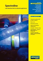
GENERAL INFORMATION<br />
The <strong>TIF</strong> <strong>RX</strong>-<strong>1A</strong> <strong>and</strong> <strong>XL</strong>-<strong>1A</strong>leak detectors are the culmination of over 30 years of Leak<br />
Detector manufacturing experience. <strong>TIF</strong> is proud to present these tools into which we<br />
have incorporated all of our experience, <strong>and</strong> years of customer feedback, in the hope<br />
of providing our valued customers with the best of everything; price, performance <strong>and</strong><br />
reliability.<br />
An advanced micro-processor is at the heart of each unit. It permits more advanced<br />
management of the circuitry <strong>and</strong> sensing tip signal than ever before possible.<br />
Additionally, the number of components used in the circuit is reduced 50%, increasing<br />
reliability <strong>and</strong> efficiency. The micro-processor monitors the sensing tip <strong>and</strong> battery voltage<br />
levels 4000 times per second, compensating for even the most minor fluctuations<br />
in signal. This translates into a stable <strong>and</strong> dependable tool in almost any environment.<br />
Convenience features have been added to enhance usability. A revolutionary new<br />
case design gives the user grip <strong>and</strong> control, <strong>and</strong> places the visual indicators<br />
(<strong>RX</strong>-<strong>1A</strong> only) in direct sight during use.<br />
Please take a few moments to read through the following pages, in order to underst<strong>and</strong><br />
<strong>and</strong> benefit from all the capabilities of your new <strong>RX</strong>-<strong>1A</strong> or <strong>XL</strong>-<strong>1A</strong>. We trust that<br />
you will be 100% satisfied with your new purchase. If you have any questions or comments<br />
after reviewing the manual, please feel free to contact us in the USA, toll free<br />
at (800) 327-5060 from 8AM to 5PM EST.<br />
FEATURES<br />
Both Models Feature:<br />
• Microprocessor controlled circuit with Advanced Digital Signal Processing<br />
• Detect ALL Halogenated refrigerants<br />
• Certified to SAE J1627 for R12, R22 & R134a<br />
• Variable frequency audible alarm<br />
• Constant Power Indication<br />
• Cordless <strong>and</strong> portable, operate on 2 C-cell batteries<br />
• 14" (35.5cm) flexible stainless probe<br />
• Spare sensing tip included<br />
• UL Classified for Intrinsic Safety<br />
• CE Approved<br />
• Carrying case included, optional holster <strong>and</strong> reference leak source<br />
• Two Year Warranty<br />
Additional Features of <strong>TIF</strong> <strong>XL</strong>-<strong>1A</strong><br />
• Single switch control<br />
Additional Features of <strong>TIF</strong> <strong>RX</strong>-<strong>1A</strong><br />
• Six segment visual leak size indicator<br />
• True mechanical pump provides positive airflow through sensing tip<br />
• High <strong>and</strong> Low sensitivity levels<br />
• One touch reset<br />
• Tactile keypad controls<br />
• Real time sensitivity adjustment<br />
Nur Autoklimaanlagen -<br />
7. Zum Lecktest des Verdampferkerns im Klimaanlagenmodul das<br />
Klimaanlagengebläse mindestens 15 Sekunden lang hochtourig laufen lassen,<br />
dann abschalten und 10 Minuten warten, damit sich das Kühlmittel im Gehäuse<br />
ansammeln kann.<br />
Hiernach die Leckdetektorsonde in den Gebläse-Widerst<strong>and</strong>sblock oder das<br />
Kondensatablaßloch einführen, wenn kein Wasser vorh<strong>and</strong>en ist, oder in die dem<br />
Verdampfer am nächsten gelegene Öffnung im Heizungs-/Lüftungs-<br />
/Klimaanlagengehäuse, wie z.B. den Heizungsschacht oder Lüftungsschacht halten.<br />
Alarmiert der Detektor, wurde wahrscheinlich ein Leck gefunden.<br />
Alle Systeme -<br />
8. Nach allen Wartungsarbeiten am Kühlmittelsystem oder nach <strong>and</strong>eren<br />
Wartungsarbeiten, die sich auf das Kühlmittelsystem auswirken, sollte an der<br />
Reparaturstelle und an den Wartungsanschlüssen des Kühlmittelsystems ein<br />
Lecktest ausgeführt werden.<br />
ANWENDUNGSMÖGLICHKEITEN<br />
Beide der Leckdetektoren <strong>TIF</strong> <strong>RX</strong>-<strong>1A</strong> und <strong>RX</strong>-<strong>1A</strong>, die durch dieses H<strong>and</strong>buch<br />
bedeckt werden, können benutzt werden:<br />
• Zur Suche nach Kühlgaslecks in Klimaanlagen, Kühlsystemen und<br />
Vorrats-/Rückgewinnungsbehältern. Dieser Detektor reagiert auf ALLE halogen-<br />
(chlor-, fluor-) haltigen Kühlmittel. Dazu gehören u.a.:<br />
CFCs, z.B.: R12, R11, R500, R503 usw.<br />
HCFCs, z.B.: R22, R123, R124, R502 usw.<br />
HFCs, z.B.: R134a, R404a, R125 usw.<br />
Mischungen wie AZ-60, HP62, MP39, R410a usw.<br />
• Zur Suche nach Ethylenoxydgaslecks in Sterilisiergeräten in Krankenhäusern<br />
(Erkennung von halogenisiertem Trägergas)<br />
• Zur Suche nach SF-6 in Hochspannungsunterbrechern<br />
• Zur Suche nach den meisten Gasen, die Chlor, Fluor und Brom enthalten<br />
(Halogengase)<br />
• Zur Suche nach Reinigungsstoffen in Trockenreinigungsanlagen, z.B.<br />
Perchlorethylen<br />
• Zur Suche nach Halongasen in Feuerlöschsystemen<br />
WARTUNG<br />
Es ist wichtig, daß der Leckdetektor ordnungsgemäß gewartet wird. Folgende<br />
Anweisungen genau befolgen, um Betriebsprobleme zu verringern und die<br />
Haltbarkeit des Geräts zu verlängern.<br />
WARNUNG: DAS GERÄT VOR DEM REINIGEN ODER DEM AUSWECHSELN<br />
DER SONDENSPITZE AUSSCHALTEN. STROMSCHLAGGEFAHR!<br />
Die Sondenspitze sauberhalten: Die mitgelieferte Schutzkappe verwenden, um<br />
zu verhindern, daß sich Staub, Feuchtigkeit und Fett auf der Spitze ansammeln.<br />
Das Gerät nie ohne aufgesetzte Schutzkappe betreiben.<br />
Vor Gebrauch des Geräts immer erst die Spitze und die Schutzkappe auf Schmutzund/oder<br />
Schmiermittelablagerungen untersuchen. Zum Reinigen:<br />
1. Die Schutzkappe an der Spitze anfassen und abziehen.<br />
2. Die Schutzkappe mit einem Tuch und/oder Druckluft reinigen.<br />
3. Ist die Sonde selbst schmutzig, kann sie einige Sekunden lang in eine<br />
milde Lösung getaucht werden, z.B. Alkohol. Dann mit Druckluft und/oder einem<br />
27
BETRIEBSHINWEISE<br />
Der folgende Abschnitt enthält verschiedene allgemeine Betriebshinweise und das<br />
gemäß SAEJ1628 empfohlene Lecksuchverfahren.<br />
1. In stark mit Gas kontaminierten Bereichen kann das Gerät zurückgesetzt werden,<br />
um die in der Umgebung befindlichen Gaskonzentrationen zu ignorieren.<br />
Die Sonde darf während des Rücksetzens nicht bewegt werden. Das Gerät kann<br />
beliebig oft rückgesetzt werden.<br />
3. In windigen Bereichen lassen sich selbst große Lecks nur schwer feststellen.<br />
Unter diesen Bedingungen ist es am besten, wenn der vermutliche Leckbereich<br />
abgeschirmt wird.<br />
3. Es ist durchaus möglich, daß der Detektor ein Alarmsignal abgibt, wenn die<br />
Sondenspitze mit Feuchtigkeit und/oder Lösungen in Kontakt kommt. Ein solcher<br />
Kontakt ist daher bei der Lecksuche zu vermeiden.<br />
SAE J1628 Empfohlenes Verfahren<br />
HINWEIS: Bei Autoklimaanlagen den Lecktest nur bei ausgeschaltetem Motor<br />
durchführen.<br />
1. Die Klimaanlage bzw. das Kühlsystem sollte mit ausreichend Kühlmittel geladen<br />
sein, so daß im ausgeschalteten Zust<strong>and</strong> auf dem Manometer mindestens 340<br />
kPa (50 psi) angezeigt werden. Bei Temperaturen unter 15° C (59° F) können<br />
u.U. keine Lecks gemessen werden, da dieser Druck nicht erreicht wird.<br />
2. Darauf achten, daß die Detektorsondenspitze nicht kontaminiert wird, wenn ein<br />
kontaminiertes Teil getestet wird. Ist das Teil stark verschmutzt oder im Fall von<br />
Kondensation (Feuchtigkeit), sollte das Teil erst mit einem trockenen Lappen<br />
abgewischt oder mit Werkluft abgeblasen werden. Keine Reinigungs- oder<br />
Lösungsmittel verwenden, da der Detektor möglicherweise auf deren<br />
Best<strong>and</strong>teile reagiert.<br />
3. Das gesamte Kühlsystem anschauen, um Zeichen von ausströmendem<br />
Klimaanlagen-Schmiermittel, Beschädigungen und Korrosion an allen Leitungen,<br />
Schläuchen und Bauteilen ausfindig zu machen. Die fraglichen Bereiche mit der<br />
Detektorsonde abtasten, besonders alle Anschlüsse, Schlauchkupplungen,<br />
Kühlmittelsteuerungen, Wartungsanschlüsse mit aufgesetzten Kappen, hartgelötete<br />
oder geschweißte Stellen sowie die Bereiche der Leitungs- und<br />
Bauteilbefestigungen.<br />
4. Stets dem Verlauf des Kühlmittelsystems folgend testen, damit kein potentielles<br />
Leck übergangen wird. Falls ein Leck festgestellt wird, trotzdem das restliche<br />
System nach weiteren Lecks absuchen.<br />
5. In allen zu untersuchenden Bereichen die Sonde nicht schneller als 25 bis 50<br />
mm/s (1-2 in./sec) durch den Testbereich bewegen und nicht weiter als 5 mm<br />
(1/4 in.) von der Oberfläche weghalten. Ein langsameres und näheres Abtasten<br />
erhöht die Chancen, daß ein Leck erkannt wird (siehe Abb. 2 s.6). Jedes<br />
beschleunigtes Ticken weist auf ein Leck hin.<br />
6. Ein mögliches Leck muß mindestens einmal wie folgt bestätigt werden:<br />
a) Nach Bedarf Werkluft in den Bereich des vermuteten Lecks blasen und den<br />
Bereich erneut untersuchen. Bei sehr großen Lecks hilft ein Ausblasen des<br />
Bereichs mit Werkluft oftmals bei der genauen Bestimmung der undichten<br />
Stelle.<br />
b) Die Sonde erst an die frische Luft halten, und die Einstellung überprüfen. Dann<br />
die Sondenspitze so nahe wie möglich an die vermutliche Leckstelle halten und<br />
langsam hin- und herbewegen, bis das Leck bestätigt ist.<br />
5<br />
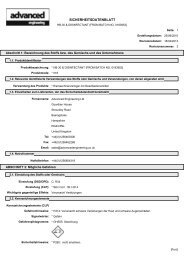
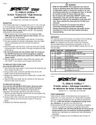
PARTS & CONTROLS<br />
1 Sensing Tip<br />
2 Tip Protector<br />
3 Flexible Probe<br />
4 Constant Power Indicator<br />
5 Power On/Off<br />
6 LED Leak Indicators<br />
(<strong>RX</strong>-<strong>1A</strong> only)<br />
7 Reset Button<br />
(<strong>RX</strong>-<strong>1A</strong> Only)<br />
8 High Sensitivity<br />
(<strong>RX</strong>-<strong>1A</strong> Only)<br />
9 Low Sensitivity<br />
(<strong>RX</strong>-<strong>1A</strong> Only)<br />
1<br />
2<br />
4<br />
GETTING STARTED<br />
Installing Batteries<br />
5<br />
3<br />
4<br />
Fig.1<br />
1. Remove the battery compartment door located on the bottom of the unit by sliding<br />
up, as shown above. Install batteries, Positive Polarity towards the battery cover<br />
(See Figure 1a).<br />
4<br />
5<br />
9<br />
1<br />
2<br />
6<br />
8<br />
7<br />
9<br />
4<br />
7<br />
6<br />
8<br />
26<br />
3
4<br />
OPERATING FEATURES<br />
Constant Power Indication<br />
The Constant Power indicator allows the user to see the battery level at all times.<br />
<strong>TIF</strong> <strong>XL</strong>-<strong>1A</strong> - The Red LED will remain on whenever the unit is powered on. If the<br />
LED is dim, or is not lit, this is an indication that the batteries should be replaced.<br />
<strong>TIF</strong> <strong>RX</strong>-<strong>1A</strong> - The first LED (leftmost) in the bargraph will remain on whenever<br />
the unit is powered on. If the LED is dim, or is not lit, this is an indication that the<br />
batteries should be replaced.<br />
Automatic Circuit/Reset Feature<br />
Both detectors feature an Automatic circuit that sets the unit to ignore ambient concentrations<br />
of refrigerant. The <strong>RX</strong>-<strong>1A</strong> additionally features a Reset<br />
function key for convenience.<br />
• Automatic Circuit - Upon initial power on, the unit automatically sets itself to<br />
ignore the level of refrigerant present at the tip. Only a level, or concentration,<br />
greater than this will cause an alarm.<br />
CAUTION: Be aware that this feature will cause the unit to ignore any refrigerant<br />
present at turn on. In other words, with the unit off if you place the tip up to a<br />
known leak <strong>and</strong> switch the unit on, no leak will be indicated!<br />
• Reset Feature - Resetting the unit during operation performs a similar function, it<br />
programs the circuit to ignore the level of refrigerant present at the tip. This<br />
allows the user to 'home-in' on the source of the leak (higher concentration).<br />
Similarly, the unit can be moved to fresh air <strong>and</strong> reset for maximum sensitivity.<br />
Resetting the unit with no refrigerant present (fresh air) causes any level above<br />
zero to be detected.<br />
To Reset the unit:<br />
<strong>XL</strong>-<strong>1A</strong> - Switch the unit OFF <strong>and</strong> back ON again<br />
<strong>RX</strong>-<strong>1A</strong> - Press the RESET key. Whenever the unit is reset, all LED's will light for 1<br />
second. This provides a visual confirmation of the reset action.<br />
Sensitivity Adjustment (<strong>RX</strong>-<strong>1A</strong> Only)<br />
The <strong>TIF</strong> <strong>RX</strong>-<strong>1A</strong> provides two levels of sensitivity. The base beeping tone is an<br />
indication of sensitivity level; the quicker beep rate indicates a higher level. When<br />
the unit is switched on, it is set to the high sensitivity position.<br />
1. To change the sensitivity, press the LO key. When the key is pressed, the visual<br />
display will momentarily show the four left LED's red. The base beep rate will<br />
slow, indicating Low Sensitivity level.<br />
2. To switch back to High Sensitivity, press the HI key. The three right LED's will<br />
light momentarily, <strong>and</strong> the base beep rate quickens.<br />
Automatische Schalttechnik – Wenn das Gerät zum ersten Mal eingeschaltet<br />
wird, stellt sich das Gerät automatisch so ein, daß es das an der Sensorspitze<br />
vorh<strong>and</strong>ene Kühlmittelniveau ignoriert. Nur ein Niveau bzw. eine Konzentration,<br />
die dieses übersteigt, löst einen Alarm aus.<br />
VORSICHT: Dabei ist zu bedenken, daß aufgrund dieser Funktion das Gerät<br />
sämtliches Kühlmittel ignoriert, das beim Einschalten vorh<strong>and</strong>en ist. Mit <strong>and</strong>eren<br />
Worten, wenn das Gerät ausgeschaltet ist und die Sensorspitze an ein bekanntes<br />
Leck gehalten wird, wird kein Leck angezeigt!<br />
Rückstellfunktion – Das Rückstellen des Geräts während des Betriebs bringt ein<br />
ähnliches Ergebnis, denn dadurch wird der Schaltkreis so programmiert, daß das<br />
an der Sensorspitze vorh<strong>and</strong>ene Kühlmittelniveau ignoriert wird. Dies ermöglicht<br />
dem Benutzer ein Feststellen der Leckquelle (höhere Konzentration). Ähnlich<br />
verhält es sich, wenn das Gerät im Freien verwendet und für maximale<br />
Empfindlichkeit rückgestellt wird. Durch ein Rückstellen des Geräts, wenn kein<br />
Kühlmittel vorh<strong>and</strong>en ist (frische Luft), wird die Feststellung eines beliebigen<br />
Niveaus über null ermöglicht.<br />
Rückstellen des Geräts:<br />
<strong>XL</strong>-<strong>1A</strong> – Das Gerät aus- und wieder einschalten.<br />
<strong>RX</strong>-<strong>1A</strong> –Die Taste RESET (RÜCKSTELLEN) drücken, um das Gerät rückzustellen.<br />
Alle LEDs leuchten 1 Sekunde lang auf. Dies ist die optische Bestätigung,<br />
daß das Gerät rückgestellt wurde.<br />
Einstellen der Empfindlichkeit (nur <strong>RX</strong>-<strong>1A</strong>)<br />
Das <strong>TIF</strong> <strong>RX</strong>-<strong>1A</strong> verfügt über zwei Empfindlichkeitsniveaus. Der akustische Basiston<br />
zeigt eines der Empfindlichkeitsniveaus an: die schnellere Tonfolge weist auf ein<br />
höheres Niveau hin. Beim Einschalten des Geräts ist es auf die hohe<br />
Empfindlichkeitsposition eingestellt.<br />
1. Die Empfindlichkeit durch Drücken der Taste LO (NIEDRIG) ändern. Nachdem<br />
die Taste niedergedrückt worden ist, leuchten auf der optischen Anzeige die vier<br />
linken roten LEDs kurz auf. Der akustische Basiston verlangsamt sich, wodurch<br />
das Empfindlichkeitsniveau Lo (Niedrig) angezeigt wird.<br />
2. Soll auf hohe Empfindlichkeit zurückgeschaltet werden, die Taste HI (HOCH)<br />
drücken. Die drei rechten LEDs leuchten kurz auf, und der Basiston wird<br />
schneller.<br />
BETRIEBSANLEITUNG<br />
1. Das Gerät einschalten.<br />
<strong>XL</strong>-<strong>1A</strong> – Den ON/OFF- (EIN/AUS) Schalter in die Position ON schalten.<br />
<strong>RX</strong>-<strong>1A</strong> – Die Taste I/O- (EIN/AUS) (rot und grün) drücken. Alle LEDs leuchten<br />
zwei Sekunden lang auf. In dieser Zeit führt das Gerät einen Eigentest durch.<br />
2. Nun ist ein gleichmäßiger Ton zu hören.<br />
3. Den Batteriest<strong>and</strong> überprüfen. Dazu die konstante Energieversorgungsanzeige<br />
beobachten (siehe oben).<br />
4. Mit der Suche nach Lecks beginnen. Wenn Kühlmittel entdeckt wird, ändert sich<br />
der akustische Ton in einen sirenenähnlichen Ton, der sich vom Basiston deutlich<br />
unterscheidet.<br />
<strong>RX</strong>-<strong>1A</strong> – Zusätzlich leuchten nachein<strong>and</strong>er die optischen Anzeiger gemäß<br />
Beschreibung im Abschnitt Alarmanzeigen auf.<br />
5. <strong>RX</strong>-<strong>1A</strong> – Mit den Tasten HIGH (HOCH) und LOW (NIEDRIG) kann die<br />
Empfindlichkeit jederzeit während des Betriebs eingestellt werden.<br />
6. Falls ein voller Alarm ausgelöst wird, bevor die Leckquelle festgestellt werden<br />
25
5<br />
1<br />
2<br />
4<br />
1 Sondenspitze<br />
2 Schutzkappe<br />
3 Flexsonde<br />
4 Betreibsschaler<br />
5 Strom Ein/Aus<br />
6 LED-Leckanzeigen (nur <strong>RX</strong>-<strong>1A</strong>)<br />
7 Rücksetztaste (nur <strong>RX</strong>-<strong>1A</strong>)<br />
8 Hohe Empfindlichkeit (nur <strong>RX</strong>-<strong>1A</strong>)<br />
9 Niedrige Empfindlichkeit (nur <strong>RX</strong>-<strong>1A</strong>)<br />
Geräteteile und Bedienelemente<br />
Installieren der Batterien<br />
1. Zum Einsetzen der Batterien den Verschluß des Batteriefachs unten am Gerät<br />
wie gezeigt herausschieben, und Batterien einlegen. Der positive Pol muss rückwärts,<br />
gegen verschluß, zeigen. (siehe Abb. 1a).<br />
Konstante Energieversorgungsanzeige<br />
5<br />
3<br />
4<br />
Fig. 1<br />
Mit der konstanten Energieversorgungsanzeige kann der Benutzer jederzeit das<br />
Batterieniveau überprüfen.<br />
<strong>TIF</strong> <strong>XL</strong>-<strong>1A</strong> – Die rote LED-Anzeige bleibt erleuchtet, solange das Gerät<br />
eingeschaltet ist. Wenn die LED-Anzeige mit jedem akustischen Ton „pulsiert“,<br />
nur schwach oder gar nicht erleuchtet ist, deutet dies darauf hin, daß die<br />
Batterien ersetzt werden sollten.<br />
<strong>TIF</strong> <strong>RX</strong>-<strong>1A</strong> – Die erste LED-Anzeige (ganz links) im Balkendiagramm bleibt<br />
erleuchtet, solange das Gerät eingeschaltet ist. Wenn die LED-Anzeige mit<br />
jedem akustischen Ton „pulsiert“, nur schwach oder gar nicht erleuchtet ist,<br />
deutet dies darauf hin, daß die Batterien ersetzt werden sollten.<br />
Automatische Schalttechnik / Rückstellfunktion<br />
Beide Detektoren sind mit einer automatischen Schalttechnik ausgestattet, durch<br />
die das Gerät Kühlmittelkonzentrationen in der Umgebung ignoriert. Der <strong>RX</strong>-<strong>1A</strong><br />
verfügt außerdem über eine bequeme Rückstellfunktion.<br />
4<br />
5<br />
9<br />
1<br />
2<br />
6<br />
7<br />
8<br />
Seitenansicht<br />
BATTERIEFACHVERSCHLUSS<br />
9<br />
4<br />
7<br />
BATTERIEN<br />
6<br />
8<br />
OPERATING INSTRUCTIONS<br />
1. Switch the unit on<br />
<strong>XL</strong>-<strong>1A</strong> - Move the ON/OFF switch to the ON position.<br />
<strong>RX</strong>-<strong>1A</strong> - Press the "I/O" (Red <strong>and</strong> Green) key. All LED's will light for two seconds<br />
as the unit performs a self check.<br />
2. The unit will begin beeping at a steady rate.<br />
3. Verify the battery level by observing the constant power indicator (see above).<br />
4. Begin searching for leaks. When refrigerant is detected, the audible tone will<br />
change to a 'siren' type sound, distinctly different from the base beep rate.<br />
<strong>RX</strong>-<strong>1A</strong> - Additionally, the visual indicators will light progressively as described in<br />
the Alarm Indications section.<br />
5. <strong>RX</strong>-<strong>1A</strong> - Sensitivity can be adjusted at any time during operation by using the HI<br />
or LO keys.<br />
6. If a full alarm occurs before the leak is pinpointed, RESET the unit as described<br />
above, to reset the circuit to a zero reference.<br />
OPERATING TIPS<br />
The following section includes several general operating tips, <strong>and</strong> the SAE J1628<br />
recommended procedure for leak detection.<br />
1. In areas that are heavily contaminated with gas, the unit may be reset to block<br />
out ambient concentrations of gas. The probe should not be moved while the<br />
unit is being reset. The unit can be reset as many times as needed.<br />
2. In windy areas, even a large leak can be difficult to find. Under these conditions,<br />
it is best to shield the potential leak area.<br />
3. Be aware that the detector may alarm if the sensing tip comes in contact with<br />
moisture <strong>and</strong>/or solvents. Therefore, avoid contact with these when leak checking.<br />
SAE J1628 Recommended Procedure<br />
NOTE: On Automotive A/C Systems, test with the engine not in operation.<br />
1. The air conditioning or refrigeration system should be charged with sufficient<br />
refrigerant to have a gauge pressure of at least 340 kPa (50 psi) when not in<br />
operation. At temperatures below 15° C (59° F) leaks may not be measurable,<br />
since this pressure may not be reached.<br />
2. Take care not to contaminate the detector probe tip if the part being tested is<br />
contaminated. If the part is particularly dirty, or condensate (moisture) is present<br />
it should be wiped off with a dry shop towel or blown off with shop air. No cleaners<br />
or solvents should be used, since the detector may be sensitive to their<br />
ingredients.<br />
3. Visually trace the entire refrigerant system, <strong>and</strong> look for signs of air conditioning<br />
lubricant leakage, damage, <strong>and</strong> corrosion on all lines, hoses, <strong>and</strong> components.<br />
Each questionable area should be carefully checked with the detector probe, as<br />
well as all fittings, hose to line couplings, refrigerant controls, service ports with<br />
caps in place, brazed or welded areas, <strong>and</strong> areas around attachment points <strong>and</strong><br />
hold-downs on lines <strong>and</strong> components.<br />
24 5
6<br />
OPERATING TIPS<br />
4. Always follow the refrigerant system around in a continuous path so that no<br />
areas of potential leaks are missed. If a leak is found, always continue to test the<br />
remainder of the system.<br />
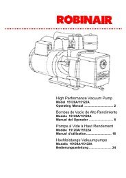
5. At each area checked, the probe should be moved around the location, at a rate<br />
no more than 25 to 50 mm/second (1-2 in/second), <strong>and</strong> no more than 5 mm (1/4<br />
in) from the surface, completely around the position. Slower <strong>and</strong> closer movement<br />
of the probe greatly improves the likelihood of finding a leak (see Fig. 2,<br />
below). Any increase in beep rate is indicative of a leak.<br />
Fig. 2<br />
6. An apparent leak shall be verified at least once as follows:<br />
a) Blow shop air into the area of the suspected leak, if necessary, <strong>and</strong> repeat the<br />
check of the area. In cases of very large leaks, blowing out the area with shop<br />
air often helps locate the exact position of the leak.<br />
b) First move the probe to fresh air <strong>and</strong> reset. Then hold the probe tip as close<br />
as possible to the indicated leak source <strong>and</strong> slowly move around it until the leak<br />
is confirmed.<br />
Automotive A/C Systems only -<br />
7. Leak testing of the evaporator core while in the air conditioning module shall be<br />
accomplished by turning the air conditioning blower on high for a period of 15<br />
seconds minimum, shutting it off, then waiting for the refrigerant to accumulate in<br />
the case for 10 minutes.<br />
After such time, insert the leak detector probe into the blower resistor block or<br />
condensate drain hole, if no water is present, or into the closest opening in the<br />
heating/ventilation/air conditioning case to the evaporator, such as the heater<br />
duct or a vent duct. If the detector alarms, a leak apparently has been found.<br />
All Systems -<br />
8. Following any service to the refrigerant system <strong>and</strong> any other service which disturbs<br />
the refrigerant system, a leak test of the repair <strong>and</strong> of the service ports of<br />
the refrigerant system should be done.<br />
DEUTSCH<br />
<strong>TIF</strong> <strong>XL</strong>-<strong>1A</strong> und <strong>TIF</strong> <strong>RX</strong>-<strong>1A</strong><br />
AUTOMATISCHER HALOGEN-LECKDETEKTOR<br />
Die Leckdetektoren <strong>TIF</strong> <strong>RX</strong>-<strong>1A</strong> und <strong>XL</strong>-<strong>1A</strong> sind das Ergebnis von 30 Jahren<br />
Erfahrung in der Herstellung von Leckdetektoren. <strong>TIF</strong> ist stolz darauf, diese Geräte<br />
vorstellen zu können, denn in sie haben wir alle unsere Erfahrung und den jahrelangen<br />
Feedback unserer Kunden integriert, in der Hoffnung, unseren geschätzten<br />
Kunden das Beste hinsichtlich Preis, Leistung und Zuverlässigkeit zu bieten.<br />
Den Kern eines jeden Geräts bildet ein Mikroprozessor. Er gestattet ein<br />
Schalttechnik- und Sensorspitzensignal-Management, das fortschrittlicher denn je<br />
ist. Außerdem konnte die Anzahl der im Schaltkreis verwendeten Bauteile um 50 %<br />
reduziert werden, wodurch sich Zuverlässigkeit und Effizienz erhöhen. Der<br />
Mikroprozessor überwacht die Sensorspitzen- und Batteriespannungsebenen 4000<br />
mal pro Sekunde, wodurch selbst die geringfügigsten Signalabweichungen ausgeglichen<br />
werden. Daraus ergibt sich ein stabiles und zuverlässiges Gerät für<br />
nahezu jede Umgebung.<br />
Es wurden besondere Merkmale hinzugefügt, die eine erhöhte Verwendbarkeit<br />
zulassen. Ein revolutionäres neues Gehäusedesign ermöglicht verbesserten Griff<br />
und Kontrolle durch den Verbraucher und bietet gute Sicht auf die Anzeigen<br />
während des Gebrauchs (nur beim <strong>RX</strong>-<strong>1A</strong>).<br />
Nehmen Sie sich bitte etwas Zeit, um folgende Seiten durchzulesen, damit Sie alle<br />
Vorteile Ihres neuen <strong>RX</strong>-<strong>1A</strong> oder <strong>XL</strong>-<strong>1A</strong> verstehen und nutzen können. Wir sind<br />
davon überzeugt, daß Sie mit Ihrem Neukauf völlig zufrieden sein werden.<br />
MERKMALE<br />
• Mikroprozessorsteuerung mit fortschritlicher Digitalsignalverarbeitung<br />
• Erkennt ALLE Kühlmittel auf Halogenbasis<br />
• Zulassung gemäß SAE J1627 für R12, R22 & R134a<br />
• Akustisches signal der variablen frequenz<br />
• Batteriesspannungsanzeige<br />
• Schnurlos und tragbar, von 2 batterien der Größe “C” betrieben<br />
• 35,5 cm lange flexsonde aus edelstahl<br />
• Inklusive sondenspitze<br />
• Zulassung gemäß UL<br />
• Zulassung gemäß CE<br />
• Inklusive Tragenkoffer<br />
• Optionales trageholster<br />
• Optionale referenz-leckquelle<br />
• 2 jahre garantie<br />
Zusätzliche Merkmale des <strong>TIF</strong> <strong>XL</strong>-<strong>1A</strong><br />
• Steuerung mit nur einem Schalter<br />
Zusätzliche Merkmale des <strong>TIF</strong> <strong>RX</strong>-<strong>1A</strong><br />
• Sechs Segmente umfassender optischer Leckgrößenanzeiger<br />
• Rein mechanische Pumpe liefert positive Luftströmung durch Sensorspitze<br />
• Hohe und niedrige Empfindlichkeitsniveaus<br />
• Rückstellung mit nur einem Tastendruck<br />
• Tastsensorgesteuerte Tastaturen<br />
• Echtzeitempfindlichkeit Justage<br />
D<br />
E<br />
U<br />
T<br />
S<br />
C<br />
H<br />
23
DONNEES TECHNIQUES<br />
Alimentation:<br />
3V CC; deux piles alcalines «C»<br />
Sensibilité: Suivant critère d’évaluation SAE J1627;<br />
Agréé pour R12, R22 et R134a @ 14gr/an<br />
Sensibilité maximum: <strong>XL</strong>-<strong>1A</strong> Moins de 11 gr/an,<br />
<strong>RX</strong>-<strong>1A</strong> Moins de 7 gr/an, pour tous les<br />
réfrigérants à base d’halogènes<br />
Longevité de la tête<br />
de détection: <strong>XL</strong>-<strong>1A</strong> 40 heures environ<br />
<strong>RX</strong>-<strong>1A</strong> 30 heures environ<br />
Température de<br />
fonctionnement:<br />
0° - 52°C (entre 30°et 125°F)<br />
Durée de vie des piles:<br />
Environ 30 heures en utilisation normale<br />
Facteur de marche:<br />
Continu, pas de limites<br />
Temps de réponse:<br />
Instantané<br />
Temps de remise<br />
à zéro:<br />
Une seconde<br />
Temps de<br />
réchauffement:<br />
Environ 2 secondes<br />
Poids de l’appareil:<br />
560 grammes<br />
Dimensions de<br />
l’appareil:<br />
22,9 cm x 6,5 cm x 6,5 cm)<br />
Longueur de la sonde<br />
fixéé:<br />
35,5 cm<br />
GARANTIE ET REPARATIONS<br />
Cet instrument a été conçu et fabriqué pour vous offrir un service illimité. Si cet<br />
appareil ne fonctionne pas après avoir effectué l’entretien recomm<strong>and</strong>é, nous nous<br />
engageons envers l’acheteur original à réparer ou échanger gratuitement l’appareil<br />
si la réclamation est faite dans les deux ans suivant la date d’achat. Cette garantie<br />
est valable sur tous les instruments réparables qui n’ont pas fait l’objet de réparations<br />
non-autorisées ou été endommagés suite à un usage incorrect. Cette garantie<br />
ne couvre pas les piles, les têtes de détection, les protecteurs de tête ou toutes<br />
autres pièces qui s’usent lors de l’utilisation normale de l’instrument.<br />
Avant de retourner votre instrument pour réparations, assurez-vous que vous avez<br />
soigneusement consulté le chapitre Entretien de l’Appareil dans ce mode d’emploi<br />
pour déterminer si le problème ne peut être facilement résolu. Assurez-vous que<br />
vous ayez soit remplacé ou nettoyé la tête de détection et son protecteur et que les<br />
piles sont en bon état AVANT de retourner l’appareil. Si l’appareil ne fonctionne toujours<br />
pas convenablement, envoyez-le au service de réparation dont l’adresse figure<br />
au dos de ce manuel. Les instruments réparés ou échangés feront l’objet d’une<br />
garantie supplémentaire de 90 jours.<br />
APPLICATIONS<br />
Both of the Leak Detectors covered by this manual may be used to:<br />
• Detect refrigerant gas leaks in Air Conditioning or Refrigeration systems <strong>and</strong><br />
storage/recover containers. These detectors will respond to ALL halogenated<br />
(contains Chlorine or Fluorine) refrigerants. This includes, but is not limited to:<br />
CFCs e.g. R12,R11,R500,R503 etc...<br />
HCFCs e.g. R22,R123,R124,R502 etc...<br />
HFCs e.g. R134a, R404a, R125 etc...<br />
Blends such as AZ-50, HP62, MP39, R410a etc...<br />
• Detect Ethylene Oxide gas leaks in hospital sterilizing equipment (detects halogenated<br />
propellant)<br />
• Detect SF-6 in high voltage circuit breakers<br />
• Detect most gases that contain Chlorine, Fluorine <strong>and</strong> Bromine (halogen gases)<br />
• Detect cleaning agents used in dry cleaning applications such as<br />
perchloroethylene.<br />
• Detect Halon gases in fire extinguishing systems<br />
MAINTENANCE<br />
Proper maintenance of your Leak Detector is very important. Carefully following the<br />
instructions, outlined below, will reduce performance problems <strong>and</strong> increase the life<br />
expectancy of the unit.<br />
WARNING: TURN UNIT OFF BEFORE REPLACING THE SENSING TIP. FAILURE<br />
TO DO SO MAY RESULT IN A MILD ELECTRICAL SHOCK!<br />
Keep the sensing tip clean: Prevent dust, moisture <strong>and</strong> grease build-up by utilizing<br />
the provided tip protector. Never use the unit without the protector in place.<br />
Before using the unit always inspect the tip <strong>and</strong> protector to see that they are free of<br />
dirt <strong>and</strong>/or grease. To clean:<br />
1. Remove protector by grasping <strong>and</strong> pulling off tip.<br />
2. Clean protector with shop towel <strong>and</strong>/or compressed air.<br />
3. If the tip itself is dirty it can be cleaned by immersing in a mild solvent, such as<br />
alcohol, for a few seconds, <strong>and</strong> then using compressed air <strong>and</strong>/or a shop towel<br />
to clean.<br />
NOTE: Never use solvents such as gasoline, turpentine, mineral spirits, etc... as<br />
these will leave a detectable residue <strong>and</strong> desensitize your unit.<br />
Sensing tip replacement: The tip will eventually wear out <strong>and</strong> require replacement.<br />
It is difficult to predict exactly when this will occur since tip longevity is directly<br />
related to the conditions <strong>and</strong> frequency of use. The tip should be replaced whenever<br />
the alarm sounds or becomes erratic, in a clean, pure, air environment.<br />
22<br />
7
MAINTENANCE<br />
To replace the tip:<br />
1. Make sure the unit is OFF.<br />
2. Remove the old tip by unscrewing counter-clockwise.<br />
3. Use the supplied replacement tip, located in the carrying case. Replace by<br />
screwing on clockwise.<br />
REPLACEMENT PARTS<br />
St<strong>and</strong>ard Equipment<br />
Your Halogen Leak Detector comes equipped with one Carrying Case, one Owner's<br />
Manual, <strong>and</strong> one replacement Sensing Tip.<br />
To purchase replacement parts for you leak detector please contact your local <strong>TIF</strong><br />
distributor. To ensure that you obtain the correct parts it is best to reference the part<br />
number when placing your order.<br />
Replacement Parts<br />
Part #<br />
<strong>TIF</strong>XP-2<br />
<strong>TIF</strong>XP-4A<br />
<strong>TIF</strong>5201<br />
Part Description<br />
Maintenance Kit<br />
3 Sensing Tips<br />
3 Tip Protectors<br />
Blow Molded Carrying Case<br />
Reference Leak Source<br />
ENTRETIEN<br />
Un entretien suivi est essentiel pour votre Détecteur de Fuite. En suivant les instructions<br />
ci-dessous à la lettre, vous réduirez les problèmes d’utilisation et prolongerez<br />
la vie utile de l’appareil.<br />
ATTENTION: ETEIGNEZ L’UNITE AVANT DE REMPLACER LA TETE DE DETEC-<br />
TION. LE NON-RESPECT DE CETTE PRECAUTION PEUT ENTRAINER UN<br />
LEGER CHOC ELECTRIQUE!<br />
La tête de détection doit rester propre: Evitez l’accumulation de poussière, d’humidité<br />
et de graisse en utilisant le protège-tête fourni. N’utilisez jamais l’appareil sans<br />
que le protège-tête soit en place.<br />
Avant d’utiliser l’appareil, inspectez toujours la tête et son protecteur pour voir s’ils<br />
ne sont pas sales ou enduits de graisse. Pour nettoyer:<br />
1. Enlevez le protecteur en le retirant de la tête.<br />
2. Nettoyez le protecteur avec un chiffon et/ou de l’air comprimé.<br />
3. Si la tête est sale, elle peut être nettoyée en la plongeant dans un produit<br />
solvant doux, tel que de l’alcool, pour quelques secondes, et ensuite en utilisant<br />
de l’air comprimé et/ou un chiffon pour la nettoyer.<br />
REMARQUE: N’employez jamais de produits solvants tels que de l’essence, de la<br />
térébenthine, du white-spirit, etc...parce qu’ils laissent un résidu détectable et<br />
réduisent la sensibilité de votre appareil.<br />
Remplacement de la tête de détection: la tête finira par s’user et devra être<br />
remplacée. Il est difficile de prévoir exactement qu<strong>and</strong> cela se passera étant donné<br />
que la vie utile de la tête est directement liée aux conditions ainsi qu’à la fréquence<br />
d’utilisation. La tête devrait être remplacée lorsque la fréquence du bip augmente ou<br />
devient irrégulière, même dans une atmosphère propre, pure et aérée.<br />
Pour remplacer la tête:<br />
1. Assurez-vous que l’appareil est éteint (en position OFF).<br />
2. Retirez la vielle tête en dévissant dans le sens inverse des aiguilles<br />
d’une montre.<br />
3. Utilisez la tête de remplacement qui est fournie, logée dans le<br />
compartiment des piles, et vissez la dans le sens des aiguilles d’une<br />
montre jusqu’à ce qu’elle soit bien serrée à la main.<br />
PIECES DE RECHANGE<br />
Equipement St<strong>and</strong>ard<br />
Votre Détecteur de Fuite de Gaz Halogènes est livré avec une mallette, un mode<br />
d’emploi, 2 piles «C» et une tête de détection de rechange ainsi que son protecteur.<br />
Pour acheter des pièces de rechange pour votre détecteur de fuite, veuillez contacter<br />
votre distributeur le plus proche. Pour être certain d’obtenir la pièce correcte,<br />
nous vous conseillons de donner le numéro de référence de la pièce lorsque vous la<br />
comm<strong>and</strong>ez.<br />
Pièces de Rechange<br />
8<br />
<strong>TIF</strong>XP-2<br />
<strong>TIF</strong>XP-4A<br />
<strong>TIF</strong>5201<br />
Jeu d’entretien (3 têtes de détection<br />
et 3 protecteurs de tête)<br />
Mallette de luxe<br />
Source de fuite<br />
21
4. Suivez toujours le système de réfrigération en parcourant des routes continues<br />
afin qu’aucune zone pouvant présenter des fuites ne soit oubliée. Si vous trouvez<br />
une fuite, poursuivez toujours le test du reste du circuit.<br />
5. Pour l’inspection complète de chaque zone, la sonde devrait être déplacée<br />
autour de cette dernière à une vitesse ne dépassant pas 25 à 50mm/seconde<br />
(1-2 pouces/seconde) et à une distance de la surface ne dépassant pas 5mm<br />
(1/4 de pouce). Un mouvement plus lent et plus rapproché de la sonde améliore<br />
fortement la possibilité de trouver une fuite (voir Fig. 2 p.6). Toute augmentation<br />
de la fréquence des bips indique la présence d’une fuite.<br />
6. Une fuite apparente sera vérifiée au moins une fois de la manière suivante:<br />
a) Appliquez de l’air comprimé dans la zone de la fuite suspecte s’il y alieu et<br />
répétez la vérification. Pour les cas de fuites importantes, l’application d’air<br />
comprimé sur la zone aidera à la localisation exacte de la fuite.<br />
b) Exposez d’abord la sonde à l’air frais et remettez la à zéro. Maintenez la<br />
tête de la sonde aussi près que possible de la source de la fuite et déplacez<br />
la lentement jusqu’à ce que la fuite soit confirmée.<br />
Systèmes de climatisation automobile uniquement<br />
7. La détection de fuite du noyau de l’évaporateur lorsqu’il se trouve dans le module<br />
de climatisation sera réalisée en mettant la soufflerie de la climatisation en<br />
position maximum pour une durée minimum de 15 secondes, en l’éteignant, puis<br />
en attendant 10 minutes pour que le réfrigérant s’accumule dans le boîtier pendant<br />
10 minutes.<br />
Une fois ce laps écoulé, insérez la sonde du détecteur de fuite dans le bloc de la<br />
résistance de la soufflerie ou l’orifice d’évacuation du condensateur, s’il n’y a pas<br />
d’eau, ou dans l’ouverture la plus proche de l’évaporateur dans le boîtier de<br />
chauffage/ventilation/climatisation, comme la conduite de chauffage ou de ventilation.<br />
Si l’alarme du détecteur retentit, une fuite a été apparemment trouvée.<br />
SPECIFICATIONS<br />
3V DC; two “C" cell Alkaline batteries<br />
Maximum Sensitivity:<br />
Ultimate sensitivity<br />
<strong>TIF</strong><strong>XL</strong>-<strong>1A</strong><br />
Per SAE J1627 Rating Criteria<br />
Certified @ 0.5 oz/yr. (14gr/yr)<br />
less than 0.4 oz/yr (11 gr/yr) for all<br />
Halogen based refrigerants.<br />
<strong>TIF</strong><strong>RX</strong>-<strong>1A</strong><br />
less than 0.25 oz/yr (7 gr/yr) for all<br />
Halogen based refrigerants.<br />
Sensing Tip Life: Approximately 20 hours<br />
Operating Temperature: 30° -125° F (0° to 52° C)<br />
Battery Life:<br />
<strong>TIF</strong><strong>XL</strong>-1:<br />
Approximately 40 hours normal use<br />
<strong>TIF</strong><strong>RX</strong>-<strong>1A</strong>:<br />
Approximately 30 hours normal use<br />
Duty Cycle:<br />
Continuous, no limitation<br />
Response Time:<br />
Instantaneous<br />
Reset Time:<br />
One second<br />
Warm-Up Time:<br />
Approximately 2 Seconds<br />
Unit Weight:<br />
1.2 pounds (560 grams) (with batteries)<br />
Unit Dimensions: 9" x 2.5" x 2.5"<br />
(22.9cm x 6.5cm x 6.5cm)<br />
Probe Cord Length: 14" or 35.5 cm<br />
WARRANTY & REPAIR<br />
Power<br />
Supply:<br />
Tous systèmes<br />
8. Après tout entretien du système de réfrigération ou toute intervention qui perturbe<br />
le système de réfrigération, un test de détection de fuite de la réparation et<br />
des orifices de service du système de réfrigération devrait être effectué.<br />
APPLICATIONS<br />
Les Détecteur de Fuites <strong>XL</strong>-1 u <strong>RX</strong>-<strong>1A</strong> peut aussi être utilisant pour:<br />
• Détecter les fuites de gaz réfrigérants dans d’autres systèmes et<br />
conteneurs de stockage et de récupération. Ces détecteurs réagiront à<br />
TOUS les réfrigérants halogènes (contiennent des gaz Chlorés ou<br />
Fluorés). Leur liste comprend mais n’est pas limitée à:<br />
CFCs ex: R12, R11, R500, R503 etc...<br />
HCFCs ex: R22, R123, R 124, R502 etc....<br />
HFCs ex: R134a, R404a, R125 etc....<br />
Des mélanges tels que: AZ-50, HP62, MP39 R410a etc....<br />
• Détecter les fuites d’Oxyde d’Ethylène dans les équipements hospitaliers de<br />
stérilisation (détectera les gaz propulseurs halogènes)<br />
• Détecter (le gaz) SF-6 dans les disjoncteurs à haute tension<br />
• Détecter la plupart des gaz qui contienne du Chlore, du Fluor et du<br />
Brome (gaz halogènes)<br />
• Détecter les agents nettoyants utilisés pour le nettoyage à sec commele<br />
perchloroéthylène.<br />
• Détecter les gaz halon dans les systèmes d’extinction d’incendie.<br />
This instrument has been designed <strong>and</strong> manufactured to provide unlimited service.<br />
Should the unit be inoperative, after performing the recommended maintenance, a<br />
no-charge repair or replacement will be made to the original purchaser if the claim is<br />
made within TWO years from the date of purchase. This warranty applies to all<br />
repairable instruments that have not been tampered with or damaged through<br />
improper use. This warranty does not cover batteries, sensing tips, tip protectors, or<br />
any other materials that wear out during normal operation of the instrument.<br />
Before returning your instrument for repair please make sure that you have carefully<br />
reviewed the Unit Maintenance section of this manual to determine if the problem<br />
can be easily repaired. Make sure that you have either replaced or cleaned the<br />
sensing tip <strong>and</strong> tip protector <strong>and</strong> that the batteries are working properly BEFORE<br />
returning the unit. If the instrument still fails to work properly please call the<br />
Customer Service Department for an RMA number (800) 327-5060. Pack the instrument<br />
<strong>and</strong> send the unit to the repair facility address on the back cover of this manual.<br />
Repaired or replaced tools will carry an additional 90 day warranty. For more<br />
information please call (800) 327-5060.<br />
20<br />
9
10<br />
ESPAÑOL<br />
<strong>TIF</strong> <strong>XL</strong>-<strong>1A</strong> Y <strong>TIF</strong> <strong>RX</strong>-<strong>1A</strong><br />
DETECTOR AUTOMATICO DE FUGAS DE HALOGENO<br />
Los detectores de fugas <strong>TIF</strong> <strong>RX</strong>-<strong>1A</strong> y <strong>XL</strong>-<strong>1A</strong> son la culminación de más de 30 años<br />
de experiencia en la fabricación de Detectores de Fugas. <strong>TIF</strong> se enorgullece de<br />
presentar estos instrumentos a los cuales se les ha incorporado toda nuestra experiencia,<br />
y años de comentarios y sugerencias de nuestros clientes, con la esperanza<br />
de proporcionar a nuestros valiosos clientes lo mejor de todo: precio, rendimiento y<br />
confiabilidad.<br />
El corazón de cada unidad es un avanzado microprocesador. Esto permite un<br />
manejo más avanzado de los circuitos y de la señal de la punta sensora de lo que<br />
era posible con anterioridad. Adicionalmente, el número de componentes utilizados<br />
en el circuito se reduce al 50%, con un aumento en la confiabilidad y la eficiencia.<br />
El micorprocesador monitorea los niveles de voltaje de la batería y de la punta sensora<br />
4000 veces por segundo, compens<strong>and</strong>o las más pequeñas fluctuaciones en la<br />
señal. Esto se traduce en un instrumento estable y confiable en casi todo tipo de<br />
medio ambiente.<br />
Se han añadido características de comodidad para mejorar su valor práctico. Un<br />
nuevo y revolucionario diseño del estuche le da al usuario mejor agarre y control, y<br />
coloca los indicadores visuales (<strong>RX</strong>-<strong>1A</strong> solamente) en visualización directa durante<br />
su uso.<br />
Sírvase emplear algunos minutos para leer las páginas siguientes completamente,<br />
para que comprenda y saque el mayor provecho de todas las capacidades de su<br />
nuevo <strong>RX</strong>-<strong>1A</strong> o <strong>XL</strong>-<strong>1A</strong>. Confiamos en que estará 100% satisfecho con su<br />
nueva compra.<br />
CARACTÉRISTICAS<br />
• Control for microprocesador, procesamiento avanzado de señal digital<br />
• Detecta todas los halogenados refrigerantes<br />
• Certificado de SAE J1627 for R12, R22 & R134a<br />
• Alarma audible de la frecuencia variable<br />
• Deseñalización constante del suministro de engería de eléctrica<br />
• Sin cordón y portátil, pera con 2 baterías de exemento <br />
• Sonda flexible de acero inoxidable de 14” (35,5 cm)<br />
• Incluye punta sensora<br />
• Certificado de UL<br />
• Certificado de CE<br />
• Incluye estuche portador incluido, funda opcional<br />
• Fuente de fuga de referencia opcional<br />
• Dos años de garantía<br />
Características adicionales del <strong>TIF</strong> <strong>XL</strong>-<strong>1A</strong><br />
• Un solo interruptor de control<br />
UTILISATION<br />
1. Allumez l’appareil<br />
<strong>XL</strong>-<strong>1A</strong> – Mettez l’interrupteur ON/OFF (MARCHE/ARRET) en position ON.<br />
<strong>RX</strong>-<strong>1A</strong> – Appuyez sur la touche « I/O » (Rouge et Vert). Toutes les DEL s’allumeront<br />
pendant deux secondes pendant que l’appareil effectue des tests<br />
automatiques.<br />
2. L’appareil commencera à bîper à une fréquence régulière.<br />
3. Vérifiez le niveau de la pile en observant le témoin d’alimentation constante (voir<br />
ci-dessus).<br />
4. Commencez à chercher des fuites. Lorsque le réfrigérant est détecté, le ton<br />
audible se transformera en un son de type « sirène » fortement différent de la<br />
fréquence du bîpe de base.<br />
<strong>RX</strong>-<strong>1A</strong> – En outre, les témoins visuels s’allumeront progressivement comme<br />
décrit dans la section Indications de l’Alarme.<br />
5. <strong>RX</strong>-<strong>1A</strong> – la sensibilité peut être réglée à tout moment durant le fonctionnement<br />
en utilisant les touches HIGH ou LOW.<br />
6. Si l’alarme retentit avant que la fuite soit localisée avec précision, REMETTEZ<br />
l’appareil A ZERO comme décrit ci-dessus pour remettre le circuit à zéro comme<br />
référence.<br />
CONSEILS D’UTILISATION<br />
La section suivante comprend plusieurs conseils d’utilisation, et la procédure recomm<strong>and</strong>ée<br />
par la norme SAEJ1628 pour la détection de fuites.<br />
1. Dans des endroits fortement contaminés par le gaz, vous pouvez remettre l’appareil<br />
à zéro pour bloquer la contamination ambiante de gaz. La sonde ne<br />
devrait pas être déplacée lorsque vous êtes en train de la remettre à zéro.<br />
L’appareil peut être remis à zéro autant de fois que cela s’avérera nécessaire.<br />
2. Dans les endroits exposés au vent, même une fuite importante peut être<br />
extrêmement difficile à trouver. Dans de pareilles conditions, il est souvent<br />
nécessaire d’abriter l’endroit ou se trouve la fuite potentielle.<br />
3. Soyez conscient du fait que l’alarme du détecteur peut se déclencher si la tête<br />
de la sonde entre en contact avec de l’humidité et/ou des produits solvants.<br />
Essayez d’éviter tout contact avec ces facteurs perturbateurs lorsque vous<br />
essayez de détecter une fuite.<br />
Procédures recomm<strong>and</strong>ées selon les normes SAE J1628<br />
REMARQUE: Sur les systèmes de climatisation automobiles, procédez à la détection<br />
de fuite avec le moteur arrêté.<br />
1. Le système de climatisation ou de réfrigération devrait être chargé avec suffisamment<br />
de réfrigérant pour afficher une pression à la jauge d’au moins 340kPa<br />
(50psi) lorsqu’il n’est pas en marche. A des températures inférieures à 15°C<br />
(59°F), il se peut que les fuites ne puissent pas être mesurées, étant donné que<br />
cette pression peut ne pas être atteinte.<br />
2. Prenez soin de ne pas contaminer la tête de la sonde du détecteur si la pièce<br />
testée est contaminée. Si la pièce est particulièrement sale, ou en présence de<br />
condensation (humidité), elle devrait être essuyée avec un chiffon sec ou séchée<br />
à l’air comprimé. N’employez pas de produits nettoyants ou solvants car le<br />
détecteur est sensible à leurs ingrédients.<br />
3. Inspectez visuellement le système entier de réfrigération, et cherchez des traces<br />
de fuite de lubrifiants de climatisation, de dommages et de corrosion sur tous<br />
les conduites, tuyaux et composants. Chaque zone douteuse devrait être<br />
soigneusement vérifiée avec la sonde du détecteur, ainsi que tous les raccords,<br />
joints des tuyaux aux conduites, contrôles de réfrigérant, orifices de service avec<br />
capuchons en place, zones brasées ou soudées et zones dans la proximité des<br />
points de raccord et de fixation des conduites et composants.<br />
19
18<br />
Instructions D'Installation De Batterie<br />
1. Retirez la porte de soute de batterie située sur le bas de l'instrument près du<br />
glissement vers le haut, comme montré ci-dessous. Installez les batteries,<br />
polarité positive à l'extérieur (vers la porte de batterie). (voir le schéma 1a).<br />
Témoin d’alimentation constante<br />
Le témoin d’alimentation constante permet à l’utilisateur de voir le niveau de la pile<br />
à tout instant.<br />
<strong>TIF</strong> <strong>XL</strong>-<strong>1A</strong> – La DEL rouge restera allumée chaque fois que l’appareil est en<br />
marche. Si les DEL « pulsent » à chaque son audible, est atténuée, ou n’est<br />
pas allumée, c’est une indication que les piles devraient être remplacées.<br />
<strong>TIF</strong> <strong>RX</strong>-<strong>1A</strong> – La première DEL (à l’extrême gauche) dans le diagramme à barres<br />
restera allumée chaque fois que l’appareil est en marche. Si la DEL « pulse »<br />
à chaque son audible, est atténuée, ou n’est pas allumée, c’est une indication<br />
que les piles devraient être remplacées.<br />
Circuit automatique/Dispositif de remise à zéro<br />
Les deux détecteurs possèdent un circuit automatique qui règle l’appareil pour<br />
qu’il ignore le niveau de réfrigérant présent à la pointe. Seul un niveau ou une<br />
concentration supérieure à celle-ci déclenchera l’alarme.<br />
ATTENTION: Ce dispositif fera en sorte que l’appareil ignore la présence de tout<br />
réfrigérant lorsqu’il est allumé. En d’autres termes, lorsque l’appareil est éteint, si<br />
vous placez la pointe près d’une fuite connue et allumez l’appareil, aucune fuite<br />
ne seras indiquée!<br />
Dispositif de remise à zéro – La remise à zéro durant son fonctionnement<br />
accomplit une fonction similaire; elle programme le circuit pour qu’il ignore le<br />
niveau de réfrigérant présent à la pointe. Ceci permet à l’utilisateur de dépister la<br />
source de la fuite (concentration plus élevée). Pareillement, l’appareil peut être<br />
déplacé dans de l’air frais et remis à zéro pour obtenir une sensibilité maximum.<br />
La remise à zéro de l’appareil en présence de réfrigérant (air frais) entraîne la<br />
détection de tout niveau au dessus de zéro.<br />
Remise à zéro de l’appareil :<br />
<strong>XL</strong>-<strong>1A</strong> – Eteignez (OFF) et rallumez (ON) l’appareil.<br />
<strong>RX</strong>-<strong>1A</strong> – pressez la touche de REMISE A ZERO, chaque fois que l’appareil est<br />
remis à zéro, toutes les DEL s’allumeront pendant 1 seconde. Ceci donnera une<br />
confirmation visuelle de l’action de remise à zéro.<br />
Réglage de la sensibilité (<strong>RX</strong>-<strong>1A</strong> seulement)<br />
Le <strong>TIF</strong> <strong>RX</strong>-<strong>1A</strong> fournit deux niveaux de sensibilité. Le ton de base du bîpe est une<br />
indication du niveau de sensibilité ; Plus le bîpe est rapide, plus le niveau est élevé.<br />
Lorsque l’appareil est allumé, il est réglé sur la position sensibilité élevée.<br />
1. Pour changer la sensibilité, appuyez sur la touche LO (basse). Lorsque vous<br />
appuyez sur la touche, les quatre DEL sur la gauche du témoin lumineux deviendront<br />
rouges momentanément. La fréquence de base du bîpe ralentira, indiquant<br />
le niveau de sensibilité basse.<br />
2. Pour repasser en sensibilité élevée, appuyez sur la touche HI (élevée). Les trois<br />
DEL sur la droite s’allumeront momentanément et la fréquence du bîpe s’accélérera.<br />
Características adicionales del <strong>TIF</strong> <strong>RX</strong>-<strong>1A</strong><br />
• Indicador visual de seis segmentos del tamaño de la fuga<br />
• Una bomba mecánica proprociona flujo de aire positivo a través de la punta sensora<br />
• Niveles altos y bajos de sensibilidad<br />
• Restauración del equipo puls<strong>and</strong>o un botón<br />
• Teclado de control<br />
• Ajuste de sensibilidad de tiempo real<br />
Piezas y Controles<br />
5<br />
1<br />
2<br />
4<br />
1 Punta sensora<br />
2 Protector de la punta<br />
3 Sonda flexible<br />
4 Indicador de enegía<br />
5 Encendido/Apagado<br />
6 Indicadores LED de fuga (<strong>RX</strong>-1 solamente)<br />
7 Botón de reajuste (<strong>RX</strong>-1 solamente)<br />
8 Alta sensibilidad (<strong>RX</strong>-1 solamente)<br />
9 Baja sensibilidad (<strong>RX</strong>-1 solamente)<br />
Instalación de las baterías<br />
Quite la puerta del compartimiento de baterías ubicada en el fondo de la unidad<br />
deslizándola hacia arriba, como se muestra a continuación. Instale las baterías con<br />
la polaridad positiva hacia la tapa del compartimiento (vea la Figura 1a).<br />
Indicación constante de energía<br />
5<br />
Fig. 1<br />
3<br />
4<br />
Vista lateral<br />
TAPA DE LABATERIA<br />
BATERIA<br />
El indicador constante de energía permite el usuario ver el nivel de la batería en<br />
todo momento.<br />
<strong>TIF</strong> <strong>XL</strong>-<strong>1A</strong> – El diodo lumínico (LED) rojo permanecerá encendido siempre que la<br />
unidad esté activada. Si el LED “destella” con cada tono audible, está opaco, o no<br />
se ilumina, es una indicación de que se deben reemplazar las baterías.<br />
<strong>TIF</strong> <strong>RX</strong>-<strong>1A</strong> - El primer LED (extrema izquierda) en el histograma permanecerá<br />
encendido siempre que la unidad esté activada. Si el LED “destella” con cada tono<br />
audible, está opaco, o no se ilumina, es una indicación de que se deben reemplazar<br />
las baterías.<br />
4<br />
5<br />
9<br />
1<br />
2<br />
6<br />
7<br />
8<br />
9<br />
4<br />
7<br />
6<br />
8<br />
E<br />
S<br />
P<br />
A<br />
Ñ<br />
O<br />
L<br />
11
12<br />
Carácterística de restauración/circuito automático<br />
Ambos detectores poseen un circuito automático que ajusta la unidad para que<br />
ignore las concentraciones de refrigerante en el ambiente. El <strong>RX</strong>-<strong>1A</strong> tiene además<br />
una tecla de función de Restauración para comodidad.<br />
• Circuito automático – En el momento de la activación inicial, la unidad se ajusta<br />
automáticamente para ignorar el nivel de refrigerante presente en la punta. Sólo<br />
un nivel, o concentración, mayor que este dará lugar a una alarma.<br />
AVISO: Tenga en cuenta que esta característica hará que la unidad ignore<br />
cualquier refrigerante presente al momento de encenderla. En otras palabras,<br />
con la unidad apagada, si usted coloca la punta en una fuga conocida y<br />
después la enciende, ¡no habrá indicación de fuga!<br />
• Característica de restauración – La restauración de la unidad durante la<br />
operación realiza una función similar; programa el circuito para que ignore el<br />
nivel de refrigerante presente en la punta. Esto permite al usuario ’dirigirse<br />
hacia’ la fuente de la fuga (concentración más alta). En forma similar, la unidad<br />
se puede mover hacia el aire libre y restaurar para obtener una sensibilidad<br />
máxima. La restauración de la unidad sin que haya refrigerante presente (al<br />
aire libre) hace que detecte cualquier nivel superior a cero.<br />
Para restaurar la unidad:<br />
<strong>XL</strong>-<strong>1A</strong> – Apague la unidad y Enciendala de nuevo.<br />
<strong>RX</strong>-<strong>1A</strong> – Pulse la tecla de RESET, cada vez que se restaura la unidad,<br />
todos los LED se iluminan durante 1 segundo. Esto proporciona una confirmación<br />
visual de la acción de restauración.<br />
Ajuste de la sensibilidad (<strong>RX</strong>-<strong>1A</strong> solamente)<br />
El <strong>TIF</strong> <strong>RX</strong>-<strong>1A</strong> proporciona dos niveles de sensibilidad. El tono de “beeps”de base<br />
es una indicación del nivel de sensibilidad; una frecuencia de “beeps”más rápida<br />
indica un nivel más alto. Cu<strong>and</strong>o se enciende la unidad, está ajustada a la posición<br />
de alta sensibilidad.<br />
1. Para cambiar la sensibilidad, pulse la tecla LO (baja). Cu<strong>and</strong>o se pulsa la tecla,<br />
la visualización mostrará momentáneamente los cuatro LED rojos de la izquierda.<br />
El frecuencia de “beeps”de base se hará más lenta, indic<strong>and</strong>o un nivel de<br />
baja sensibilidad.<br />
2. Para regresar al nivel de alta sensiblidad, pulse la tecla HI (alta). Los tres LED<br />
de la derecha se iluminarán momentáneamente, y la frecuencia de “beeps”de<br />
base se acelera.<br />
INSTRUCCIONES DE OPERACION<br />
1. Para encender la unidad:<br />
<strong>XL</strong>-1 - Mueva el interruptor de ON/OFF (ENCENDIDO/APAGADO) a la posición<br />
de ENCENDIDO.<br />
<strong>RX</strong>-<strong>1A</strong> – Pulse la tecla “I/O”(rojo y verde). Todos los LED se iluminarán durante<br />
dos segundos mientras la unidad realiza una autoverificación.<br />
2. La unidad comenzará a emitir “beeps” a una frecuencia uniforme.<br />
3. Verifique el nivel de las baterías observ<strong>and</strong>o el indicsdor constante de energía<br />
(ver arriba).<br />
4. Comience a buscar las fugas. Cu<strong>and</strong>o se detecte refrigerante, el tono audible<br />
cambiará a un sonido de “sirena”, claramente diferente de la frecuencia de<br />
“beeps” de base.<br />
<strong>RX</strong>-<strong>1A</strong> – Adicionalmente, los indicadores visuales se iluminarán progresivamente<br />
como se describe en la sección de Indicaciones de Alarma.<br />
• Indicateur de tension de la pile<br />
• Sans fil, fonctionne avec deux piles <br />
• Cordon flexible avec tige flexible de 35,5 cm en acier inoxydable<br />
• Tete de détectioncomprise<br />
• Répond aux normes UL<br />
• Répond aux normes CE<br />
• Mallette de transport comprise, etui de transport (en option)<br />
• Guide de référence des sources de fuites (en option)<br />
• Garantie de 2 ans<br />
Caractéristiques supplémentaires du <strong>TIF</strong> <strong>XL</strong>-<strong>1A</strong><br />
• Interrupteur de comm<strong>and</strong>e unique<br />
Caractéristiques supplémentaires du <strong>TIF</strong> <strong>RX</strong>-<strong>1A</strong><br />
• Témoin visuel à six segments indiquant le taille de la fuite<br />
• Pompe mécanique véritable qui donne une circulation d’air à travers la pointe de<br />
la sonde<br />
• Nivaux de sensibilité bas et élevés<br />
• Touche unique de remise à zéro<br />
• Comm<strong>and</strong>es par clavier numérique tactile<br />
• Réglage en temps réel de sensibilité<br />
5<br />
1<br />
2<br />
4<br />
Pieces et Comm<strong>and</strong>es<br />
1 Tête de détection<br />
Fig. 1<br />
2 Protecteur de la tête<br />
3 Sonde flexible<br />
4 Indicateur d’alimentation<br />
5 Interrupteur On/Off (Marche/Arrêt)<br />
6 Indicateurs de fuite DEL (<strong>RX</strong>-1 solamente)<br />
7 Bouton de remise à zéro (<strong>RX</strong>-1 solamente)<br />
8 Sensibilité élevée (<strong>RX</strong>-1 solamente)<br />
9 Sensibilité basse (<strong>RX</strong>-1 solamente)<br />
5<br />
3<br />
4<br />
4<br />
5<br />
9<br />
6<br />
1<br />
2<br />
7<br />
8<br />
COUVERCLE DU<br />
COMPARTIMENT<br />
POUR PILES<br />
9<br />
4<br />
Fig. 1a<br />
7<br />
Vue latérale<br />
PILES<br />
6<br />
8<br />
F<br />
R<br />
A<br />
N<br />
ÇAIS<br />
17
16<br />
Este instrumento se ha diseñado y fabricado para proporcionar servicio ilimitado. Si la<br />
unidad no funciona después de realizarse el mantenimiento recomendado, se reparará o<br />
sustituirá sin costo adicional para el comprador original si la reclamación se hace dentro<br />
del plazo de dos años a partir de la fecha de compra. Esta garantía se aplica a todos<br />
los instrumentos reparables que no han sido forzados ni dañados por un uso inapropiado.<br />
Esta garantía no cubre las baterías, las puntas sensoras, los protectores de punta ni<br />
otros materiales que se desgastan durante la operación normal del instrumento.<br />
Antes de devolver su instrumento para que lo reparen, asegúrese de haber revisado<br />
cuidadosamente la sección Mantenimiento de la Unidad de este manual para determinar<br />
si el problema se puede reparar con facilidad. Asegúrese de haber sustituido<br />
o limpiado la punta sensora y el protector de la punta, y de que las baterías estén<br />
trabaj<strong>and</strong>o en forma apropiada ANTES de devolver la unidad. Si el instrumento<br />
sigue trabaj<strong>and</strong>o incorrectamente, envíe la unidad a la dirección del servicio de<br />
reparaciones que aparece en la contraportada de este manual. Los instrumentos<br />
reparados o substituidos tendrán una garantía adicional de 90 días.<br />
FRANÇAIS<br />
<strong>TIF</strong> <strong>XL</strong>-<strong>1A</strong> ET <strong>TIF</strong> <strong>RX</strong>-<strong>1A</strong><br />
DETECTEUR DE FUITES<br />
AUTOMATIQUE DE GAZ HALOGENES<br />
Manuel de l’utilisateur<br />
Les détecteurs de fuites <strong>TIF</strong> <strong>RX</strong>-<strong>1A</strong> et <strong>XL</strong>-<strong>1A</strong> sont le résultat de plus de 30 ans<br />
d’expérience dans la fabrication de détecteurs de fuites. <strong>TIF</strong> est fier de ces outils<br />
dans lesquels nous avons incorporé toute notre expérience et des années de commentaires<br />
de nos clients dans l’espoir de leur offrir les meilleurs prix, performances<br />
et fiabilité.<br />
Un micro-processeur du dernier cri est au coeur de chaque appareil. Il permet une<br />
gestion plus avancée et inégalée dans le passé des ensembles de circuits et du signal<br />
de la pointe de la sonde. En outre, le nombre de composants utilisés dans le circuit<br />
est réduit de 50%, accroissant ainsi la fiabilité et l’efficacité. Le microprocesseur<br />
contrôle la pointe de la sonde et les niveaux de tension de la pile 4000<br />
fois par seconde, compensant les fluctuations les plus infimes dans le signal. Ceci<br />
se traduit par un outil stable et fiable dans la plupart des environnements.<br />
Des caractéristiques pratiques ont été ajoutées pour accroître sa capacité d’utilisation.<br />
Une conception nouvelle et révolutionnaire du boîtier fournit une bonne prise<br />
et un bon contrôle à l’utilisateur, et place les témoins visuels (<strong>RX</strong>-<strong>1A</strong> seulement) en<br />
pleine vue durant son utilisation.<br />
Veuillez prendre quelques instants pour lire les pages suivantes afin de comprendre<br />
et de pouvoir utiliser toutes les capacités de votre nouveau <strong>RX</strong>-<strong>1A</strong> ou <strong>XL</strong>-<strong>1A</strong>. Nous<br />
sommes persuadés que vous serez satisfait à 100% de votre nouvel achat.<br />
CARACTÉRISTIQUES<br />
• Comm<strong>and</strong>e ar microprocesseur, avec Traitement Numérique des Signaux de<br />
Pointe<br />
• Détecte TOUS les réfrigérants halogènes<br />
• Réspond aux normes SAE J1627 for R12, R22 & R134a<br />
• Alarme sonore defréquence varible<br />
5. <strong>RX</strong>-<strong>1A</strong> – La sensibilidad se puede ajustar en cualquier momento durante la<br />
operación mediant el uso de las teclas de HI o LO.<br />
6. Si se produce una alarma total antes de localizar la fuga, RESTAURE la unidad<br />
como se describe con anterioridad, para restaurar el circuito a la referencia cero.<br />
SUGERENCIAS DE OPERACION<br />
La sección siguiente incluye varias sugerencias generales de operación y el procedimiento<br />
recomendado por la SAE J1628 para la detección de fugas.<br />
1. Ajuste la sensibilidad hacia arriba sólo cu<strong>and</strong>o no se puede encontrar una fuga.<br />
Ajuste la sensibilidad hacia abajo sólo cu<strong>and</strong>o el reajuste de la unidad no le permite<br />
«dirigirse» hacia la fuga.<br />
2. En las áreas muy contaminadas con gas, se puede reajustar la unidad para bloquear<br />
la concentración de gas en el ambiente. No se debe mover la sonda mientras se<br />
esté reajust<strong>and</strong>o la unidad. La unidad se puede reajustar todas las veces que sea<br />
necesario.<br />
3. En las áreas donde hay mucho viento, hasta una fuga gr<strong>and</strong>e puede ser muy difícil<br />
de encontrar. En estas condiciones es mejor resguardar el área de fuga potencial.<br />
Técnicas de Detección de Fugas<br />
NOTA: En los Sistemas de A/C de Automóviles, haga la prueba de fugas con el motor<br />
apagado.<br />
1. El sistema de aire acondicionado o de refrigeración debe estar cargado con suficiente<br />
refrigerante para tener una presión manométrica de, por lo menos, 340 kPa<br />
(50 lb/pulg˝) cu<strong>and</strong>o no esté funcion<strong>and</strong>o. A temperaturas inferiores a 15°C (59°F),<br />
es posible que no se puedan medir las fugas, ya que puede ser que no se alcance<br />
esta presión.<br />
2. Tenga cuidado de no contaminar la punta de la sonda detectora si la pieza que se va<br />
a examinar está contaminada. Si la pieza está particularmente sucia o muestra<br />
alguna condensación (humedad), se debe limpiar con una toalla de taller seca o<br />
inyectársele aire a presión. No se deben usar limpiadores ni disolventes, porque el<br />
detector puede ser sensible a sus ingredientes.<br />
3. Revise visualmente todo el sistema refrigerante y busque señales de fugas de lubricante<br />
del aire acondicionado, daños y corrosión en todas las tuberías, mangueras y<br />
componentes. Cada área sospechosa se debe comprobar cuidadosamente con la<br />
sonda detectora, así como todos los accesorios, los acoplamientos de las<br />
mangueras con las tuberías, los controles del refrigerante, las vías de acceso de<br />
servicio con las tapas puestas, las áreas soldadas y las áreas alrededor de los puntos<br />
de unión, así como los sujetadores de las tuberías y los componentes.<br />
4. Siga siempre el trayecto del sistema refrigerante en forma continua, de manera que<br />
no queden áreas de fugas potenciales sin revisar. Si encuentra una fuga, continúe<br />
siempre comprob<strong>and</strong>o el resto del sistema.<br />
5. En cada área comprobada, la sonda se debe mover alrededor del lugar a una velocidad<br />
no mayor de 25 a 50 mm/segundo (1-2 pulgadas/segundo) y a no más de 5 mm<br />
(1/4 de pulgada) de la superficie, dándole una vuelta completa. Mover la sonda<br />
más lentamente y a menor distancia mejora mucho la probabilidad de hallar una<br />
fuga (ver Fig. 2, p.6). Cualquier incremento en la frecuencia del sonido intermitente<br />
indica que existe una fuga.<br />
6. Una fuga aparente se deberá verificar al menos una vez en la forma siguiente:<br />
a) Inyecte aire a presión en el área en que se sospecha que hay una fuga, si es<br />
necesario, y repita la comprobación del área. En casos de fugas muy gr<strong>and</strong>es,<br />
inyectar aire a presión ayuda a menudo a localizar la posición exacta de la<br />
fuga.<br />
13
) Mueva primero la sonda hacia el aire libre y reajústela. Después, sostenga la<br />
punta de la sonda lo más cerca posible del punto de fuga indicado, y muévala<br />
lentamente alrededor del mismo hasta confirmar la fuga.<br />
Sistemas de A/C de Automóviles solamente<br />
7. La prueba de fugas del núcleo del evaporador en el módulo del aire acondicionado<br />
se deberá realizar haciendo funcionar el ventilador del aire acondicionado en «high»<br />
(alto) por un período de 15 segundos como mínimo,desconectándolo y esper<strong>and</strong>o<br />
que el refrigerante se acumule en la caja durante 10 minutos.<br />
Transcurrido este tiempo, inserte la sonda detectora de fugas en el bloque de la<br />
resistencia del ventilador o en el orificio de drenaje de la condensación, si no hay<br />
agua presente, o en la abertura más cercana al evaporador tales como el conducto<br />
del calentador o un conducto de ventilación que están ubicados en la caja del aire<br />
acondicionado/ventilación/calefacción. Si el detector suena, aparentemente se ha<br />
encontrado una fuga.<br />
Todos los sistemas<br />
8. A continuación de cualquier servicio hecho al sistema refrigerante y de cualquier otro<br />
servicio que afecte dicho sistema, se debe hacer una prueba de fugas en la<br />
reparación y en las vías de acceso de servicio del sistema refrigerante.<br />
APLICACIONES<br />
Todos los Detectores de Fugas que aparecen en este manual pueden utilzarse para:<br />
• Detectar fugas en otros sistemas y en contenedores de almacenamiento y recuperación.<br />
Este detector responderá a TODOS los refrigerantes halogenados (que<br />
contienen cloro y flúor). Estos incluyen, entre otros:<br />
CFC, por ejemplo, R12, R11, R500, R503, etc...<br />
HCFC, por ejemplo, R22, R123, R124, R502, etc...<br />
HFC, por ejemplo, R134a, R404a, R125, etc...<br />
Mezclas como AZ-50, HP62, MP39 R410a etc...<br />
• Detectar fugas de gas de óxido de etileno en los equipos de esterilización de los<br />
hospitales (detectará el gas portador halogenado)<br />
• Detectar SF-6 en disyuntores de alto voltaje<br />
• Detectar la mayoría de los gases que contienen cloro, flúor y bromo (gases<br />
halógenos)<br />
• Detectar productos de limpieza utilizados en aplicaciones de lavado en seco, tales<br />
como el percloroetileno<br />
• Detectar los gases de halón en los sistemas de extinción de incendios<br />
MANTENIMIENTO<br />
El mantenimiento apropiado de su Detector de Fugas es muy importante. Seguir cuidadosamente<br />
las instrucciones que aparecen a continuación reducirá los problemas de<br />
funcionamiento y aumentará la vida útil de la unidad.<br />
ADVERTENCIA: PONGA LA UNIDAD EN ANTES DE SUBSTITUIR<br />
LA PUNTA SENSORA. DE NO HACERLO, PUEDE PRODUCIRSE UNA<br />
DESCARGA ELECTRICA LEVE.<br />
Mantenga limpia la punta sensora: Evite la acumulación de polvo, humedad y<br />
grasa utiliz<strong>and</strong>o el protector de punta que se suministra. Nunca use la unidad sin el protector<br />
puesto.<br />
Antes de usar la unidad inspeccione siempre la punta y el protector para ver si no tienen<br />
polvo y/o grasa. Para limpiar:<br />
1. Quite el protector agarrándolo y halándolo de la punta.<br />
2. Limpie el protector con una toalla de taller y/o aire comprimido.<br />
14<br />
3. Si la punta está sucia, se puede limpiar sumergiéndola en un disolvente suave,<br />
como el alcohol, durante unos segundos y después us<strong>and</strong>o aire a presión y/o una<br />
toalla de taller para limpiarla.<br />
NOTA: Nunca use disolventes como gasolina, aguarrás, alcoholes minerales, etc... ya<br />
que dejarán un residuo detectable y desensibilizarán su unidad.<br />
Sustitución de la punta sensora: Con el tiempo, la punta se desgastará y deberá<br />
sustituirse. Es difícil predecir exactamente cuándo ocurrirá esto, ya que la duración de<br />
la punta está directamente relacionada con las condiciones y la frecuencia de uso. La<br />
punta debe sustituirse cu<strong>and</strong>o la alarma suene o se vuelva errática en un ambiente de<br />
aire limpio y puro.<br />
Para substituir la punta:<br />
1. Asegúrese de que la unidad esté apagada en la posición «OFF».<br />
2. Quite la punta vieja destornillándola en sentido contrario a las manecillas del reloj.<br />
3. Use la punta de repuesto que se suministra, atornillela en el sentido de las manecillas<br />
del reloj hasta que quede apretada.<br />
Equipo estándar<br />
Su Detector de Fugas de Halógeno viene equipado con un Estuche Portátil, un Manual<br />
del Propietario y una Punta Sensora de repuesto.<br />
Para comprar piezas de repuesto para su detector de fugas, comuníquese con su distribuidor<br />
local. Para asegurarse de obtener las piezas correctas, es mejor que se refiera<br />
al número de la pieza al hacer su pedido.<br />
Piezas de repuesto:<br />
<strong>TIF</strong>XP-2<br />
<strong>TIF</strong>XP-4 A<br />
<strong>TIF</strong>5201<br />
Equipo de mantenimiento<br />
(3 puntas sensoras y 3 protectores de punta)<br />
Estuche portátil de lujo<br />
Fuente de fuga<br />
ESPECIFICACIONES<br />
Suministro de energía: 3 V CC; dos baterías alcalinas de<br />
elemento «C»<br />
Sensibilidad máxima:<br />
Según los Criterios de Clasificación<br />
SAE J1627; certificada para R12, R22 y<br />
R134a @ 14 gr/año (0.5 oz/año)<br />
Sensibilidad final: <strong>XL</strong>-<strong>1A</strong> menos de 11 gr/año (0.4 oz/año),<br />
<strong>RX</strong>-<strong>1A</strong> menos de 7 gr/año (0.25 oz/año), para todos<br />
los refrigerantes a base de halógeno.<br />
Duración de la punta sensora: Aproximadamente 20 horas<br />
Temperatura de operación: 0° a 52° C (30°a 125° F)<br />
Duración de la batería: <strong>XL</strong>-<strong>1A</strong> Aproximadamente 40 horas de uso normal<br />
<strong>RX</strong>-<strong>1A</strong> Aproximadamente 30 horas de uso normal<br />
Ciclo de trabajo:<br />
Continuo, sin límite<br />
Tiempo de respuesta:<br />
Instantánea<br />
Tiempo de reajuste:<br />
Un segundo<br />
Tiempo de calentamiento: Aproximadamente 2 segundos<br />
Peso de la unidad:<br />
560 gramos (1,2 lbs)<br />
Dimensiones de la unidad: 22,9 cm x 6,5 cm x 6,5 cm (9" x 2,5" x 2,5")<br />
Largo del cordón de la sonda: 35,5 cm (14")<br />
GARANTIA Y REPARACION<br />
15