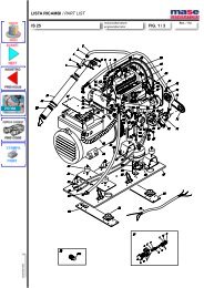
41964 MAN INSTALIS3.5-5.0.p65 - Mase Generators of North America
41964 MAN INSTALIS3.5-5.0.p65 - Mase Generators of North America
41964 MAN INSTALIS3.5-5.0.p65 - Mase Generators of North America
- No tags were found...

Create successful ePaper yourself
Turn your PDF publications into a flip-book with our unique Google optimized e-Paper software.
masemaseGENERATORSIS 3.5IS 4.0IS 5.0IS 6.0I - <strong>MAN</strong>UALE D'INSTALLAZIONEGB - INSTALLATION <strong>MAN</strong>UALF - <strong>MAN</strong>UEL D'INSTALLATIOND - INSTALLATIONSHANDBUCHREV.2 A.A. del 12-02-02 Cod. <strong>41964</strong>
INDICEIS 3.5 - 4.0 - 5.0 - 6.0IL <strong>MAN</strong>CATO RISPETTO DELLE SPECIFICHECONTENUTE NEL SEGUENTE <strong>MAN</strong>UALE DI IN-STALLAZIONE, COMPORTA IL DECADIMENTODELLA GARANZIA SUL PRODOTTO1INSTALLAZIONE1.1 Caratteristiche del vano ......................................41.2 Ancoraggio del gruppo .......................................41.3 Ventilazione .......................................................42 CIRCUITO ACQUA DI RAFFREDAMENTO2.1. Sistemi di adduzione dell'acqua di mare ............. 42.2 Tipica installazione con gruppo elettrogenosopra la linea di galleggiamento ......................... 82.3. Tipica installazione con gruppo elettrogenosotto la linea di galleggiamento ..........................82.4. Componenti ...................................................... 102.5. Sistema di scarico ........................................... 123 CIRCUITO COMBUSTIBILE3.0 Circuito combustibile ........................................ 124COLLEGAMENTO ELETTRICI4.1. Allaciamento batteria ....................................... 144.2. Allacciamento cruscotto comandi .................... 144.3. Allacciamento c.a. ........................................... 164.4. Commutazione generatore - rete ...................... 18- 2 -
INDICEIS 3.5 - 4.0 - 5.0 - 6.0THE GUARANTEE OF THE PRODUCT BECOMESVOID IF THE SPECIFICATIONS CONTAINED IN THEFOLLOWING INSTALLATION <strong>MAN</strong>UAL ARE NOTRESPECTEDLE NON-RESPECT DES DIRECTIVES REPRISESDANS CE <strong>MAN</strong>UEL D'INSTALLATION ENTRINELA DECHEANCE DE LA GARANTIE SURLE PRODUITE1INSTALLATIONE1INSTALLATION1.1 Characteristics <strong>of</strong> the installation space ............. 51.2 Fastening the unit to the ground ......................... 51.3 Ventilation ..........................................................51.1 Caracteristiques du local .................................... 51.2 Ancrage du groupe .............................................51.3 Ventilation ..........................................................52 COOLING WATER CIRCUIT2CIRCUIT D'EAU DE REFROIDISSEMENT2.1. Sea water feed system ......................................52.2 Typical installation with electric generatorabove the water-line............................................92.3. Typical installation with electric generatorbelow the water-line............................................92.4. Components .................................................... 112.5. Drainage system .............................................. 132.1. Système d'amenèe d'eau de mer ....................... 52.2 Installation typique avec groupe èlectrogèneau dessus de la ligne de flottaison ..................... 92.3. Installation typique avec groupe èlectrogènesous la ligne de flottaison ................................... 92.4. Composants .................................................... 112.5. Système de purge ............................................ 133 FUEL CIRCUIT3.0 Fuel circuit ....................................................... 133 CIRCUIT DU COMBUSTIBLE3.0 Circuit du combustible ..................................... 134ELECTRICAL CONNECTION4CONNEXIONS ELECTRIQUES4.1. Battery connection ........................................... 154.2. Control panel connection .................................. 154.3. A.C. Connection ............................................... 174.4. Generator - Mains Switching ............................ 194.1. Branchement de la batterie .............................. 154.2. Branchement du tableau de commande ........... 154.3. Raccordement c.a. ........................................... 174.4. Commutation gènèrateur-rèseau ...................... 19- 3 -
IS 3.5 - 4.0 - 5.0 - 6.01.0. INSTALLAZIONE1.1. Caratteristiche del vano- Il generatore deve essere installato in un locale sufficientementeaerato, in grado di assicurare la poca quantitàd'aria necessaria alla combustione del motore.- Il locale deve essere separato ed isolato acusticamentedalle aree abitabili.- Il generatore va posizionato in modo da facilitare lenormali operazioni di manutenzione.- E' consigliabile l'installazione nel locale dei motori dipropulsione a patto che questo sia conforme alle condizionisopracitate.- L'aria deve essere pulita.- La temperatura dell'aria nel luogo d'installazione deveessere compresa fra i -5°C e +40°C.- L'umidità relativa non deve superare il 50% ad unatemperatura massima di +40°C. Puo' essere ammessauna umidità relativa del 90% a +20°C, e 100% a +25°CIS 3.5 - 4.0515[20.28"]13[0.51"]590[23.23"]562[22.13"]13[0.51"]1.2. Ancoraggio del gruppoPer il fissaggio del gruppo, predisporre un basamento persopportare peso e vibrazioni.Procedere alla foratura del basamento seguendo le indicazionidi fig. 1Ø14[Ø0.55"]342[13.46"]1.3. VentilazioneIl generatore è dotato di un sistema interno di raffreddament<strong>of</strong>orzato attraverso uno scambiatore acqua/aria.La quantità di aria necessaria alla combustione vieneaspirata tramite l'apertura posta sul basamento (fig. 2):assicurarsi quindi che questa apertura sia sempre benlibera.IS 5.0 - 6.0565[22.24"]2.0. CIRCUITO ACQUA DI RAFFREDDAMENTOIl motore viene raffreddato nel gruppo elettrogeno da unsistema a circuito aperto nel quale circola acqua di mare.La portata del circuito acqua mare è di 1200 lt / h .All'atto dell'installazione è necessario predisporre uncircuito di adduzione dell'acqua di mare per il raffreddamentoe un sistema di scarico per la miscela di gas dicombustione ed acqua.675[26.57"]468[18.43"]406[15.98"]Fig. 1- 4 -
IS 3.5 - 4.0 - 5.0 - 6.01.0. INSTALLATION1.1. Characteristics <strong>of</strong> the installation spaceThe generator must be installed in a sufficiently airedspace, supplying a little amount <strong>of</strong> air necessary for thecombustion <strong>of</strong> the motor.The space must be separate and acoustically insulatedfrom living areas.The generator should be positioned so that normalmaintenance operations can easily be carried out.Propulsion motors are recommended for installation in thearea as long as they comply with the above-mentionedconditions.1.0. INSTALLATION1.1. Caracteristiques du localLe gènèrateur doit ètre installè dans un local suffisammentaèrè, en mesure d'assurer la faible quantitè d'air à lacombustion du moteur. Le local doit ètre sèparè et isolèdu point de vue acoustique vis-à-vis des zones habitables.Le gènèrateur doit ètre positionnè de manière à faciliterles opèrations normales d'entretien.Nous conseillons l'installation dans le local des moteursde propulsion à condition que ce local rèponde auxnormes susmentionnèes.1.2. Fastening the unit to the groundTo fasten the unit securely, a base should be installed toabsorb vibrations and support the weight.Drill holes in the base according to the instructions infig. 1.1.2. Ancrage du groupePour la fixation du groupe, prèdisposer une embase poursupporter le poids et les vibrations.Rèaliser les orifices sur cette embase en respectant lesindications de la figure 1.1.3. VentilationThe generator is equipped with an internal forced coolingsystem through a water/air exchanger.The air needed for combustion is taken in through theopening on the base (fig. 2) so care must be taken toensure that this opening is always free.1.3. VentilationLe gènèrateur est muni d'un système interne derefroidissement forcè à travers un èchangeur eau/air.La quantitè d'air nècessaire à la combustion est aspirèeà travers l'ouverture situèe sur l'embase (figure 2):s'assurer alors que cette ouverture est toujours bien libre.2.0. COOLING WATER CIRCUITIn electric generator , the motor is cooled by an opencircuitsystem in which sea water circulates.The capacity <strong>of</strong> the sea water circuit is 1200 lt / h .On installation a sea water feed circuit should be fitted forcooling and a waste system to expel the mixture <strong>of</strong> fluegas and water.2.0. CIRCUIT D'EAU DE REFROIDISSEMENTLe moteur est refroidi dans le groupe èlectrogène par unsystème à circuit ouvert dans lequel circule l'eau de mer.Le dèbit du circuit eau mer est de 1200 Litres/heure .Il faut prèdisposer, lors de l'installation, un circuit d'amenèed'eau de mer pour le refroidissement et un systèmed'èvacuation pour le mèlange de gaz de combustion etd'eau.2.1. Sea water feed systemBoats usually use one <strong>of</strong> two systems to collect water(fig. 3):1 - Direct infeed system2 - System with baffle2.1. Système d'amenèe d'eau de merLes systèmes normalement adoptès sur les embarcationspour l'introduction de l'eau sont au nombre de deux (figure3):1 - système à prise directe2 - système avec dèflecteur.- 5 -
IS 3.5 - 4.0 - 5.0 - 6.0MASE recommend the direct infeed system ref. 1 fig. 3since this system prevents water under pressure enteringthe suction ducts and instead forms a pressure which caneasily be overcome by the water pump <strong>of</strong> the electricgenerator.IMPORTANTDo not apply any type <strong>of</strong> protective hood to thedirect infeed system.THE DIRECT INFEED SYSTEM SUPPLIED BY MASEHAS BEEN MODIFIED TO PREVENT SOLID BODIESENTERING THE SYSTEM AND BLOCKING IT.IF OTHER MATERIALS AVAILABLE ON THE MARKETARE USED, MORE CARE AND MORE FREQUENTCLEANING IS NECESSARY.The baffle system might cause the following problems:a - If it is installed with the slots facing the prow.In this case, during navigation and with the electricgenerator <strong>of</strong>f, pressure is accumulated in the waterinfeed duct which might cause the system to fill up,even as far as the exhaust port, allowing water to enterthe cylinders.b - If it is installed with the slots facing the stern.In this case a depression might accumulate in thewater infeed duct during navigation, preventing thewater pump from starting up the cooling plant, orlimiting the capacity and subsequently causing theelectric generator to overheat.MASE recommande le système à prise directe rèf. 1figure 3 car ce système prèvient l'entrèe de l'eau souspression dans les conduites d'aspiration et engendre, aucontraire, une dèpression qui peut facilement ètre corrigèepar la hauteur d'èlèvation de la pompe à eau du groupeèlectrogène.IMPORTANTN'appliquer acun type de coiffe de protection ausystème à prise directeLE SYSTEME A PRISE DIRECTE LIVREE PAR LASOCIETE MASE A ETE MODIFIE POUR EVITER QUEDES CORPS SOLIDES NE PENETRENT DANSL'INSTALLATION ET NE L'OBSTRUENT.L'UTILISATION DES AUTRES MATERIAUXCOMMERCIALISES EXIGE UNE ATTENTION ACCRUEET UN NETTOYAGE PLUS FREQUENT.Par contre le système avec dèflecteur peut causer lesinconvènients suivants:a - s'il est montè avec les fentes tournèes vers l'avant.Dans ce cas, durant la navigation et avec le groupeèlectrogène èteint, une pression se crèe dans laconduite d'amenèe d'eau, d'ou un remplissage èventuelde l'installation jusqu'aux orifices de dècharge etl'entrèe possible de l'eau dans les cylindres.b - s'il est montè avec les fentes tournèes vers l'arrière.Dans ce cas, durant la navigation, une dèpressionpeut se former dans la conduite d'amenèe d'eau, aupoint d'empècher la pompe de l'eau d'enclencherl'installation de refroidissement ou au point de limiterle dèbit et donc de surchauffer le groupe èlectrogène.- 7 -
IS 3.5 - 4.0 - 5.0 - 6.02.2. Tipica installazione con gruppo elettrogenosopra la linea di galleggiamento (fig. 4)1 Presa a mare2 Rubinetto presa acqua mare3 Rubinetto svuotamento impianto4 Filtro acqua5 Gruppo elettrogeno6 Marmitta7 Silenziatore8 Bocchettone scarico a mare9 Linea di galleggiamentoFig. 4IMPORTANTEA - Tubazione diam. 45 mm. interno.B - Tubazione in gomma neoprene diam. 15 mm interno.C - Fascette di serraggio.ATTENZIONEE' molto importante rispettare le misureriportate in fig. 4-52.3. Tipica installazione con gruppo elettrogenosotto la linea di galleggiamento (fig. 5)1 Presa a mare2 Rubinetto genera impianto3 Rubinetto svuotamento impianto4 Filtro acqua5 Valvola antisifone6 Marmitta7 Silenziatore8 Bocchettone scarico a mare9 Linea di galleggiamento10 Drenaggio11 Miscelatore di scarico12 Pompa acqua13 Gruppo elettrogeno- 8 -Fig. 5
IS 3.5 - 4.0 - 5.0 - 6.02.2. Typical installation with electric generatorabove the water-line (fig. 4)2.2. Installation typique avec groupe èlectrogèneau dessus de la ligne de flottaison (fig. 4).1 Sea intake • Prise en mer2 General tap-water • Robinet gènèral de l'eau3 Tap to drain system • Robinet de vidage de l'installation4 Water filter • Filtrè à eau5 Electric generator • Groupe èletrogène6 Muffler • Pot7 Silencer • Silencieux8 Sea drainage nozzle • Goult dècharge en mer9 Water line • Ligne de flottaisonFig. 4IMPORTANTA - Tubes, internal diameter 45 mmB - Tubes, internal diameter 15 mmC - ClampsCAUTIONThe measurements shown in fig. 4-5 shouldcorrespond exactly.2.3. Typical installation with electric generatorbelow the water line (fig. 5)IMPORTANT.A - Tuyauterie d'un diamètre interne de 45 mm.B - Tuyauterie en caoutchouc Nèoprène d'un diamètreinterne de 15 mm.C - Bagues de serrage.ATTENTIONIl est très important de respecter les dimensionsindiquèes sur les figures 4 et 5.2.3. Installation typique avec groupe èlectrogènesous la ligne de flottaison (fig. 5).1 Sea intake • Prise en mer2 General tap-systemr • Robinet gènèral de l'eau3 Tap to drain system • Robinet de vidage de l'installation4 Water filter • Filtrè à eau5 Anti-siphon valve • Soupape antisiphon6 Muffler • Pot7 Silencer • Silencieux8 Sea drainage nozzle • Goult dècharge en mer9 Water line • Ligne de flottaison10 Drainage • Drainage11 Drain mixer • Mèlangeur de purge12 Water pump • Pompe à eau13 Electric generator • Goupe èletrogèneFig. 5- 9 -
IS 3.5 - 4.0 - 5.0 - 6.02.4. Componenti1 - Presa a mare del tipo diretto 1/2".IMPORTANTENel caso il gruppo venga installato ad un altezzasuperiore ad 1 Mt. sopra la linea di galleggiamento,è necessario montare una valvola di nonritorno dopo la presa a mare (fig. 6 rif. 1) cheimpedisce lo svuotamento del circuito acqua amotore spento. In caso di svuotamento ,durantel'avviamento si può danneggiare la girante dellapompa acqua; per lo stesso motivo all'atto delprimo avviamento del gruppo, è necessarioprovvedere al riempimento manuale del tubo diaspirazione dalla valvola alla pompa.2 - Rubinetto a sfera (Generale impianto) 1/2".3 - Rubinetto a sfera (Spurgo impianto) 1/2".Serve a vuotare l'impianto di raffreddamento del gruppoelettrogeno per manutenzioni generali o per periodidi lunga inattività.4 - Filtro acqua (ispezionabile).Deve proteggere efficacemente il circuito di raffreddamentodall'ingresso di fango, sabbia e alghe.1Fig. 6IMPORTANTELa rete filtrante dovrà essere del tipo fine.Si consiglia il tipo con passo 2 - 470 micron,misure diverse non consentirebbero un buonrendimento del filtro.Exhauste manifoldAnti-siphon valveFig. 7Water pump5 - Valvola antisifone: è una valvola che riporta a pressioneatmosferica il circuito di raffreddamento a motorespento, evitando il fenomeno di sifonaggio.Va obbligatoriamente usata quando il generatoreè installato col miscelatore di scarico sullao sotto la linea di galleggiamento, e va posizionatoad almeno 50 cm. sopra il livello del mare. (vedi fig.8/9).IMPORTANTEIl condotto di drenaggio della valvola antisifonedeve obbligatoriamente viaggiare al di sottodella stessa impedendo così accumuli di acquanel condotto, che deve rimanere sempre vuoto,per permettere il passaggio di aria nello stesso almomento dello spegnimento del gruppo( vedi fig. 7).ANTI-SIPHON VALVEFig. 8N.B.: Si consiglia di portare il condotto di drenaggio insentina perchè dallo stesso, durante il normale funzionamento,potrebbero fuoriuscire piccole quantità di acqua.La cassa è già predisposta con n° 2 fori per l'allacciamentodella valvola antisifone (fig. 9).- 10 -Fig. 9
IS 3.5 - 4.0 - 5.0 - 6.02.4. Components1 - Direct sea intake 1/2"IMPORTANTIf the unit is installed more than 1 metre above thewater-line, a check valve should be fitted after thesea intake (fig. 6, ref. 1) to prevent the water circuitemptying when the motor is <strong>of</strong>f. If this empties, therotor <strong>of</strong> the water pump might be damaged duringstart up; for the same reason, when the unit is firststarted up, the suction tube from the valve to thepump should be filled manually.2 - Ball tap (general) 1/2"3 - Ball tap (drainage) 1/2"This is used to drain the cooling system <strong>of</strong> the electricgenerator for general maintenance or when a longperiod <strong>of</strong> inactivity is expected.4 - Water filter (can be inspected)This must provide efficient protection for the coolingcircuit from the entrance <strong>of</strong> mud, sand and seaweed.IMPORTANTThe filter mesh should be very fine. Mesh 2 - 470micron is recommended, other sizes do not givegood filter performance.5 - Anti-siphon valve: this valve returns the cooling circuitto atmospheric pressure when the motor is switched<strong>of</strong>f, to prevent the siphon phenomenon.It must be installed when the generator is fittedwith the drainage mixer on or beneath the waterline, and should be positioned at least 50 cm abovewater level.(see fig. 8/9)IMPORTANTThe drainage duct <strong>of</strong> the anti-siphon valve mustrun beneath the valve itself in order to preventwater accumulating in the duct, which shouldalways remain empty to allow air to pass throughwhen the unit is switched <strong>of</strong>f. (see fig. 7)N.B.: The drainage duct should be taken into the bilgebecause during normal operation small quantities <strong>of</strong> watermight be leaked from the duct.The box already includes 2 holes to connect the anti-siphonvalve (fig. 9).2.4. Composants1 - Prise en mer, type direct 1/2".IMPORTANTSi le groupe est installèà une hauteur supèrieure à1 mètre au dessus de la ligne de flottaison, il fautmonter une soupape de non-retour après la prise enmer (figure 6, rèf. 1) qui empèche la vidange ducircuit de l'eau lorsque le moteur est èteint. En casde vidange, on peut endommager, durant ledèmarrage, la roue de la pompe à eau; c'est laraison pour laquelle il faut remplir manuellement letube d'aspiration de la soupape à la pompe lors dupremier dèmarrage du groupe.2 -Robinet à bille (Caractèristiques gènèrales -Installation)1/2".3 -Robinet à bille (Purge de l'Installation) 1/2".Il sert à vider l'installation de refroidissement dugroupe èlectrogène pour l'entretien gènèral ou pendantde longues pèriodes d'inactivitè.4 -Filtre à eau (inspection possible).Il doit protèger efficacement le circuit derefroidissement en empèchant l'entrèe de la boue, dusable et des algues.IMPORTANTLe rèseau de filtrage doit correspondre au typefin. Nous conseillons le type avec pas 2 - 470microns; des dimensions diffèrentes nepermettraient pas un bon rendement du filtre.5 -Soupape anti-siphon: c'est une soupape qui reconduità la pression atmosphèrique le circuit derefroidissement lorsque le moteur est èteint et permetd'èviter le phènomène de siphonnement.Elle doit ètre obligatoirement utilisèe lorsque legènèrateur est installè avec le mèlangeur depurge sur ou sous la ligne de flottaison et elle doitètre placèe à 50 cm au moins au dessus du niveau dela mer (se reporter aux figures 8 et 9).IMPORTANTLa conduite de drainage de la soupapeantisiphon doit obligatoirement passer au dessousde cette soupape, ce qui permet d'èviterl'accumulation de l'eau dans la conduite qui doittoujours ètre vide pour que l'air puisse passer lorsde la dèsactivation du groupe (se reporter à lafigure 7).NOTE: Nous conseillons de porter la conduite de drainagejusqu'à la sentine car de petites quantitès dèeau pourraients'ècouler de cette conduite durant le fonctionnement normal.La caisse est dèjà prèdisposèe avec 2 orifices pour leraccordement de la soupape antisiphon (figure 9).- 11 -
IS 3.5 - 4.0 - 5.0 - 6.02.5. Sistema di scaricoIl sistema di scarico gas di combustione/acqua delgeneratore deve essere indipendente da quello dei motoriprincipali.IMPORTANTELa lunghezza del tubo dal punto più alto delcondotto di scarico alla marmitta non deve superaremt. 2. Questo per evitare che allo spegnimentodel gruppo l'acqua rimasta nel condotto discarico possa rifluire al motore dopo aver riempitola marmitta a barilotto.1 - Marmitta a barilotto (capacità 3.5 litri).Attenua la rumorosità dello scarico ed impedisce ilriflusso dell'acqua verso il motore. Si consiglia diinstallare la marmitta a non più di 1 mt. dal generatoree di posizionarla ad una altezza uguale o inferiore aquella del basamento del generatore.2 - Silenziatore.Riduce ulteriormente la rumorosità. Si consiglia diinstallarlo ad una distanza non superiore ad 1 mt. dalbocchettone di scarico a mare.3 - Bocchettone di scarico a mare.Va installato in posizione tale da essere sempresopra il livello del mare.3.0 CIRCUITO COMBUSTIBILEL'alimentazione del gruppo è a gasolio, ed avviene tramitei raccordi contrassegnati dalle diciture "GASOLIO" e"RITORNO GASOLIO" (fig.10, rif.1-2); quest'ultimo serveper il ritorno del combustibile in eccesso. Nel collegamentoal serbatoio combustibile è necessario inserireun filtro combustibile;è inoltre buona norma inserireun rubinetto sulla linea di alimentazione a valle delserbatoio, ed una valvola unidirezionale (di non ritorno soloper dislivelli superiori a 50 cm) onde evitare lo svuotamentodell'impianto combustibile per qualsiasi causa. Utilizzareuna valvola con apertura 50 millibar.I tubi del combustibile devono essere in gomma resistenteagli idrocarburi, di diametro interno 6 mm.IMPORTANTEIl gruppo è munito di spurgo nafta automatico.Qualora fosse necessario lo spurgo manuale premereil pulsante "ON" sul pannello comandi edattendere 30 secondi prima di avviare il gruppo.1 Diesel return2 Diesel12Fig. 10IMPORTANTEIl filtro combustibile deve essere del tipo a cartucciacon grado di filtraggio da 5 a 10 micron.- 12 -
IS 3.5 - 4.0 - 5.0 - 6.02.5. Drainage systemThe flue gas/water drainage system <strong>of</strong> the generator mustbe separate from that <strong>of</strong> the main motorsIMPORTANTThe length <strong>of</strong> the tube from the highest point <strong>of</strong>the drain duct to the muffler should not exceed 2metres. This is to prevent the water left in thedrainage duct returning to the motor after fillingthe tank muffler, when the unit is turned <strong>of</strong>f.1 - Tank muffler (capacity 3.5 litres)This dampens the noise <strong>of</strong> the drainage and stops thewater flowing back towards the motor. The mufflershould be installed no less than 1 metre away from thegenerator and positioned at a height less than or equalto that <strong>of</strong> the base plate <strong>of</strong> the generator.2 - SilencerThis further reduces noise. It should be installed nomore than 1 metre from the sea drainage nozzle.3 - Sea drainage nozzle; It should be installed so that itis always above the water line..3.0. FUEL CIRCUITThe unit is fed by diesel fuel through the tubes marked“DIESEL” and “DIESEL RETURN” (fig. 10, ref. 1-2). Thislatter is used for the return <strong>of</strong> the excess fuel. It isnecessary to install a filter in connections to the fueltank, it is also advisable to fit a tap onto the power supplyline downstream <strong>of</strong> the tank and a single-acting valve(check valve only for a difference in height <strong>of</strong> 50 cm ormore) to prevent the fuel system emptying for any reason.Use a valve with a 50 millibar opening.The fuel pipes should be in hydrocarbon-resistant rubber,<strong>of</strong> inner diameter 6 mm.2.5. Système de purgeLe système de purge du gaz de combustion/eau dugènèrateur doit ètre indèpendant de celui des moteursprincipaux.IMPORTANTLa longueur du tube à partir du point le plus èlevède la conduite de purge jusqu'au pot ne doit pasdèpasser 2 mètres. Cela permet d'èviter que l'eauqui stagne dans la conduite de purge au moment dela dèsactivation du groupe puisse refluer vers lemoteur après avoir rempli le pot à barillet.1 - Pot à barillet (contenance: 3.5 litres).Il attènue le bruit de la dècharge et empèche le refluxde l'eau vers le moteur. Nous conseillons d'installer lepot à une distance non supèrieure à 1 mètre dugènèrateur et de le positionner à une hauteur ègale ouinfèrieure à celle du socle du gènèrateur.2 - Silencieux.Il attènue le bruit. Nous conseillons de l'installer à unedistance non supèrieure à 1 mètre du goulot dedècharge en mer.3 - Goulot de dècharge en mer: il doit ètre installè dansune position qui lui permette d'ètre toujours au dessusdu niveau de la mer.3.0. CIRCUIT DU COMBUSTIBLEL'alimentation du groupe, à gasoil, s'effectue parl'intermediaire des raccords portant les indications GASOILet RETOUR DU GASOIL (figure 10 - rèf. 1-2); ce derniersert pour le retour du combustible en excès. Il fautintroduire, dans le raccordement au rèservoir ducombustible, un filtre-combustible; il est de règle deplacer un robinet sur la ligne d'alimentation en aval durèservoir et une soupape unidirectionnelle (de non-retouruniquement pour les dènivellations supèrieures à 50 cm)pour èviter le vidage de l'installation de combustible,quelle que soit la cause. Utiliser une soupape avec uneouverture de 50 millibar.Les tubes du combustible, d'un diamètre interne de6 mm, doivent ètre en caoutchouc rèsistant auxhydrocarbures.IMPORTANTThe unit is fitted with automatic diesel oil drainage.If manual drainge is necessary, press the "ON"button and 30 second before set going the unit.IMPORTANTLe groupe assure une purge automatique du mazout.Si la purge manuelle ètait nècessaire, presser lebouton ON sur le panneau des commandes et attendre30 secondes avant d'activer le groupe.IMPORTANTThe fuel filter must be a "cartridge-type" with afiltering grade <strong>of</strong> 5 to 10 micronIMPORTANTLe filtre-combustible doit avoir les caractèristiquessuivantes: type à cartouche, avec un degrè defiltration de 5 à 10 microns.- 13 -
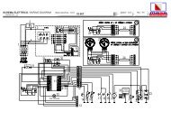
IS 3.5 - 4.0 - 5.0 - 6.04.0. COLLEGAMENTI ELETTRICI4.1. Allacciamento batteriaPer l'avviamento del gruppo è necessario utilizzare unabatteria indipendente a 12V, di capacità 18 - 30 Ah minimoEssa va allacciata al morsetto del generatore come dafig.11 con cavi di sez. 25 mm2 fino a distanze di 5 mt. concavi di sez. 35 mm2 per distanze maggiori, rispettandoquesta sequenza di operazioni:- Collegare prima il polo positivo (+) della batteria alterminale contrassegnato dal simbolo (+) sul generatore.(MOTORINO D'AVVIAMENTO)- Collegare successivamente il polo negativo (-) dellabatteria al terminale contrassegnato dal simbolo (-) sulgeneratore.- Cospargere le connessioni con specifico grasso minerale,al fine di ridurre ossidazioni o corrosioni.Il generatore è dotato di un dispositivo elettronico per laricarica automatica della batteria di avviamento, capacedi erogare 10 A, ad una tensione di 12V, a pienocarico.+Fig. 11IMPORTANTEInstallare la batteria in un vano aerato, separato dalgeneratore e da ogni dispositivo che possa provocarecalore o scintille. Verificare periodicamente lostato delle connessioni dei morsetti ed il livelloacqua batteria. Nel caso si renda necessarioscollegare i cavi, agire inversamente all'ordine raccomandatonel collegarli.Non invertire le polaritàdei cavi di connessione; il generatore e la batteriapotrebbero esserne seriamente danneggiati.Non collegare altri carichi alla batteria.132Al fine di minimizzare le correnti galvaniche il (-) dellabatteria del gruppo elettrogeno non deve essere collegatoal (-)delle altre batterie di bordo.Fig. 124.2. Allacciamento cruscotto comandiQuesto collegamento è eseguibile tramite le morsettiere(fig. 12, rif.1 ) utilizzando i cavi in dotazione già collegatial cruscotto comandi; i morsetti da usare sono rispettivamentequelli contrassegnati dal n° 1 al n° 9 per i cavicomando. Le calze di massa vanno collegate al morsett<strong>of</strong>aston (fig. 12, rif. 2 ) isolandole accuratamente eutilizzando un fast-on femmina preisolato. Nei colleganentiè necessario rispettare lo schema codice/colore riportatodi seguito (fig. 13). Bloccare inoltre il cavo con le fascettein dotazione all'apposito supporto plastico (fig. 12, rif. 3).Sul cruscotto comandi sono presenti 5 LED di funzionamentoed allarme (fig. 14, rif. 1 ), un contaore (fig.14, rif.2)- 14 -Fig. 13
IS 3.5 - 4.0 - 5.0 - 6.04.0. ELECTRICAL CONNECTIONS4.1. Battery connectionTo start <strong>of</strong>f the unit an independent battery <strong>of</strong> 12V isneeded, capacity 18 - 30 Ah min.It should be connected to the clamp <strong>of</strong> the generator asshown in fig. 11 with cables <strong>of</strong> section 25 mm 2 up todistances <strong>of</strong> 5 metres and with cables <strong>of</strong> section 35 mm 2for longer distances, and following the sequence <strong>of</strong>operations described below:- First connect the positive pole (+) <strong>of</strong> the battery to theterminal marked with the symbol (+) on the generator,(the starter).- Then connect the negative pole (-) <strong>of</strong> the battery to theterminal marked with the symbol (-) on the generator.- Wipe the connections with special mineral grease toprotect against oxidation and corrosion.The generator includes an electronic device toautomatically recharge the start-up battery, giving 10A, at a voltage <strong>of</strong> 12 V, when fully charged.IMPORTANTInstall the battery in a well-ventilated area, awayfrom the generator and from any device whichmight produce heat or sparks.Periodically check the state <strong>of</strong> the connections <strong>of</strong>the terminals and the water level <strong>of</strong> the battery. If thecables need to be disconnected, follow theinstructions for connection in reverse order.Do not invert the poles <strong>of</strong> the connecting cablessince serious damage might be caused to thegenerator and the battery.Do not connect other loads to the battery.In order to reduce galvanic currents to a minimum, the (-) <strong>of</strong> the battery <strong>of</strong> the electric generator should not beconnected to the (-) <strong>of</strong> the other batteries on board.4.2. Control panel connectionThis connection can be made through the terminal boards(fig. 12, ref. 1) using the cables provided already connectedto the control panel. The terminals to be used are thosemarked no. 1 to no. 9 for the control cables. The earthsbraid should be connected to the faston terminal (fig. 12,ref. 2) insulating them carefully and using a pre-insulatedfemale faston. In making the connections it is importantto follow the diagram and the colours codes as indicate(fig. 13). Fasten the cable with the provided plasticsupport on the bail (fig. 12, ref. 3).The control panel contains 5 LEDs for operation and alarm(fig. 14, ref. 1), an hour counter (fig. 14, ref. 2) and the startand stop buttons (fig. 14, ref. 3/4/5).For fixing the control panel is necessary to perforate asshown in fig.14.4.0. CONNEXIONS ELECTRIQUES4.1. Branchement de la batteriePour l'activation du groupe il faut utiliser une batterieindèpendante à 12 V, d'une puissance de 18 - 30 Ah auminimum.Elle doit ètre branchèe au plot du gènèrateur selon figure11 avec des càbles d'une section de 25 mm2 jusqu'à desdistances de 5 mètres et avec des càbles d'une sectionde 35 mm2 pour des distances supèrieures, en respectantcette sèquence d'opèrations:- Relier d'abord le pòle positif (+) de la batterie à la borneindiquèe par le symbole (+) sur le gènèrateur(DEMARREUR).- Relier ensuite le pòle nègatif (-) de la batterie à la borneindiquèe par le symbole (-) sur le gènèrateur.- Recouvrir les connexions de graisse minèrale pourrèduire les oxydations ou les corrosions.Le gènèrateur est muni d'un dispositif èlectronique pourla recharge automatique de la batterie de dèmarrage,capable de dèbiter 10 A, à une tension de 12 V, à pleinecharge.IMPORTANTInstaller la batterie dans un local aèrè, sèparè dugènèrateur et de tout dispositif qui puisse provoquerde la chaleur ou des ètincelles.Vèrifier pèriodiquement l'ètat des connexions desbornes et le niveau de l'eau de la batterie. Dans lecas o• il serait nècessaire de dèconnecter les càbles,respecter l'ordre inverse de celui qui avait ètèrecommandè pour la connexion.Ne jamais inverser les polaritès des càbles deconnexion; le gènèrateur et la batterie pourraientsubir une dètèrioration.Ne jamais connecter d'autres charges à la batterie.En vue de minimiser les courants galvaniques le (-) de labatterie du groupe èlectrogène ne doit pas ètre reliè au (-) des autres batteries du bord.4.2. Branchement du tableau de commandeCe branchement est rèalisable gràce aux borniers (figure12 - rèf. 1), en utilisant les càbles en dotation, dèjà relièsau tableau de commande; les bornes à utiliser sontrespectivement celles qui correspondent aux numèros de1 à 9 pour les càbles de commande. Les conducteursèlectriques de terre à tresse doivent ètre reliès à la bornefaston (figure 12 - rèf. 2), après avoir ètè soigneusementisolès et en utilisant un faston femelle prè-isolè. Lesconnexions doivent respecter le schèma code/couleurindiquè ci-après (figure 13).Bloquer enfin le càble avec les bagues en dotation sur lesupport plastique appropriè (figure 12 - rèf. 3).Sur le tableau de commande se trouvent 5 LED defonctionnement et d'alarme (figure 14 - rèf.1), un compteurhoraire (figure 14 - rèf. 2) et les boutons-poussoirs de- 15 -
IS 3.5 - 4.0 - 5.0 - 6.0ed i pulsanti di avviamento ed arresto (fig. 14, rif.3/4/5).Per fissare il cruscotto comandi occorre eseguire unaforatora come da fig. 14.IMPORTANTEIl cruscotto comandi và necessariamente installato,in quanto esso è indispensabile per il funzionamentodel gruppo: non utilizzare dispositivi diversi dalcomando fornito col gruppo, poichè essi potrebberonon essere compatibili con il generatore stesso.Eseguire l'allacciamento a batteria scollegata.ATTENZIONEIl cruscotto comandi viene fornito con un cavo dicollegamento lungo 10 metri. E' importante chequesto cavo non venga modificato, questo potrebbecausare un funzionamento improprio del circuitodel cruscotto.124153Fig. 144.3. Allacciamento c.a.Questo collegamento é eseguibile tramite la morsettieradi potenza (fig. 15, rif. 1).Questa gamma prevede la possibilità di un utilizzo sia a110 V 50 Hz - 120 V 60Hz che a 220 V 50 Hz - 240 V 60Hz.Sono perciò possibili due tipi di collegamenti (e quindi diutilizzo), secondo le seguenti configurazioni.1 - Collegamento in parallelo : in questa configurazionesi ha una unica uscita a 110 (120) V fra i punti P1 eF2, collegando le uscite dell'alternatore (P1,F1,P2,F2)secondo lo schema di fig. 16.2 - Collegamento in serie : in questa configurazione èpossibile prelevare potenza a tensione 220 (240) V frai punti P1 e F2, come lo schema di fig. 17.Nel collegamento in serie è possibile prelevare contemporaneamentela potenza sia a tensione 110 (120) V fra ipunti F1-F2 e P1-P2 che a tensione 220 (240) V fra i puntiP1 e F2, come da schema di fig. 18.E' possibile inoltre alimentare due linee separate come dafig. 19 sulle uscite P1-F1 e P2-F2.Fig. 15Fig. 16N.B.: In questo caso la potenza prelevabile da ognuna delledue uscite è la metà di quella nominale di targa.Fig. 17- 16 -
IS 3.5 - 4.0 - 5.0 - 6.0IMPORTANTThe control panel is indispensable for operating theunit and must be installed; do not use devices othetthan the control panel supplied with the unit sincethey might not be compatible with the generator.Make the connections with the battery disconnected.CAUTIONThe control panel is provided with a connectingcable 10 metres long. This cable should not bemodified since it might cause the panel circuit t<strong>of</strong>unction incorrectly.4.3. A.C. ConnectionThis connection can be done through the power terminalboard (fig. 15, ref. 1) placed inside the derivation box.This range includes the possibility <strong>of</strong> use both at 110V50Hz - 120V 60Hz and 220V 50Hz - 240V 60Hz.For this reason it is possible to make two types <strong>of</strong>connection (and use), according to the followingconfigurations.1 - Parallel configuration: in this configuration there is asingle output at 110 (120) V between points P 1and F 2,connecting the outputs <strong>of</strong> the alternator (P 1, F 1, P 2, F 2)as shown in the diagram in fig. 16.2 - Serial connection; in this configuration it is possibleto use a voltage <strong>of</strong> 220 (240) V between points P 1andF 2, as shown in the diagram in fig. 17.In serial connection, power can be picked up both at 110(120) V between points F 1- F 2and P 1- P 2and at 220 (240)V between points P 1and F 2at the same time, as shownin the diagram in fig. 18.It is also possible to feed two separate lines as shown infig. 19 on the outputs P 1- F 1and P 2- F 2.N.B. In this case the power which can be taken from each <strong>of</strong>the two outputs is half the rated nominal power.dèmarrage et d'arrèt (figure 14 - rèf. 3/4/5).Pour fixer le tableau de commande, rèaliser un orificeselon Figure 14.IMPORTANTLe tableau de commande doit ètre nècessairementinstallè car il est indispensable pour lefonctionnement du groupe: ne pas utiliser d'autresdispositifs, diffèrents de la commande livrèe avec legroupe, car ils pourraient ne pas ètre compatiblesavec le gènèrateur.Brancher après avoir dèconnectè la batterie.ATTENTIONLe tableau de commande est livrè avec un càble deliaison de 10 mètres. Il est important que ce càble nesoit pas modifiè; il pourrait en dèriver unfonctionnement inadèquat du circuit du tableau decommande.4.3. Raccordement c.a.Ce raccordement est rèalisable gràce au bornier depuissance (figure 15, rèf.1).Cette gamme prèvoit la possibilitè d'une utilisation aussibien à 110 V 50 Hz - 120 V 60 Hz qu'à 220 V 50 Hz - 240V 60 Hz.Deux types de raccordements (et donc d'utilisation) sontpar consèquent possibles selon les configurationssuivantes:1 -Liaison en parallèle: dans cette configuration nousavons une seule sortie à 110 (120) V entre les pointsP1 et F2, en reliant les sorties de l'alternateur (P1, F1,P2, F2) selon le schèma de la figure 16.2 - Liaison en sèrie: dans cette configuration on peutprèlever la puissance à une tension 220 (240) V entreles points P1 et F2 selon le schàma de la figure 17.Dans la liaison en sèrie on peut pr_lever simultanèment lapuissance à une tension de 110 (120) V entre les pointsF1-F2 et P1-P2 qu'à une tension de 220 (240) V entre lespoints P1 et F2, selon le schèma de la figure 18.On peut en outre alimenter deux lignes sèparèes selon lafigure 19 sur les sorties P1-F1 et P2-F2.NOTE: Dans ce cas la puissance que l'on peut prèlever dechacune des deux sorties est la moitiè de celle nominalefigurant sur la plaque.- 17 -
IS 3.5 - 4.0 - 5.0 - 6.0- Assicurarsi che la somma dei carichi da alimentare nonsuperi la potenzanominale del gruppo elettrogeno.- Nonostante che il gruppo sia dotato di termico fig. 21,si raccomanda di interporre fra generatore e utenzeelettriche protezioni magnetotermiche o similari, secondole tabelle di seguito riportate.- Per ottenere i collegamenti sia in parallelo che in serieutilizzare sulla morsettiera fig. 15 rif. 1 gli appositiponticelli dati in dotazione negli accessori del gruppoelettrogeno.Distribuzione a tensione unicaFig. 18TAB 1IS 3.5Hz 50 60 50 60V 110 120 220 240W. 2700 2900 2700 2900A 24.5 24.2 12.3 12.1IS 5.0 - 6.0Hz 50 60 50 60V 110 120 220 240W. 4000 4800 4000 4800A 36.5 40 18 20CARICOLOADCHARGECARICOLOADCHARGEFig. 19NB. In questi casi va installato un solo magnetotermico, vedifig. 16/17.Distribuzione a tensione doppia (Tab. 2)RETEMAINSRESEAUIS 3.5 IS 5.0 - 6.0Hz 50 50V 110/220 110/220W 2700 4000A 12.3 18Hz 60 60V 120/240 120/240W 2900 4800A 12.1 20CARICOLOADCHARGEFig. 20NB. In questi casi vanno installati due magnetotermici,vedi fig. 18/19, dimensionati sui valori di corrente (A)riportati in Tab. 24.4. Commutazione generatore - reteE' necessario interporre sulla linea di utilizzo un commutatoreche permetta di commutare le utenze dal generatoread una linea di alimentazione esterna. Il commutatoreva dimensionato in base all'entità dei carichi in gioco;uno schema di massima è rappresentato in fig. 20.- 18 -Fig. 21
IS 3.5 - 4.0 - 5.0 - 6.0- Ensure that the sum <strong>of</strong> the loads to be supplied does notexceed the nominal power <strong>of</strong> the electric generator.- Magnetothermic protective devices or similar should beplaced between the generator and electrical equipment,according to the tables shown below.- To make both parallel and serial connections, use thespecial bridges provided in the accessories to theelectric generator on the terminal board fig. 15 ref. 1.Single voltage distribution- S'assurer que la somme des charges à alimenter nesoit pas supèrieure à la puissance nominale du groupeèlectrogène.- Nous recommandons de placer, entre le gènèrateur etles applications èlectriques, des protectionsmagnètothermiques ou similaires, selon les tableauxque nous reportons ci-après.- Pour obtenir des liaisons aussi bien en parallèle qu'ensèrie utiliser sur le bornier figure 15 - rèf. 1 les barrettesapproprièes, livrèes avec les accessoires du groupeèlectrogène.Distribution à tension unique.TAB 1IS 3.5Hz 50 60 50 60V 110 120 220 240W. 2700 2900 2700 2900A 24.5 24.2 12.3 12.1TAB 1IS 3.5Hz 50 60 50 60V 110 120 220 240W. 2700 2900 2700 2900A 24.5 24.2 12.3 12.1IS 5.0 - 6.0IS 5.0 - 6.0Hz 50 60 50 60V 110 120 220 240W. 4000 4800 4000 4800A 36.5 40 18 20Hz 50 60 50 60V 110 120 220 240W. 4000 4800 4000 4800A 36.5 40 18 20N.B: In these cases just one magnetothermic device should beinstalled, see fig. 16/17.NOTE: Un seul magnètothermique doit ètre installè dans ce cas(se reporter à la figure 16/17).Double voltage distributionDistribution à tension doubleIS 3.5 IS 5.0 - 6.0Hz 50 50V 110/220 110/220W 2700 4000A 12.3 18Hz 60 60V 120/240 120/240W 2900 4800A 12.1 20IS 3.5 IS 5.0 - 6.0Hz 50 50V 110/220 110/220W 2700 4000A 12.3 18Hz 60 60V 120/240 120/240W 2900 4800A 12.1 20N.B: In these cases two magnetothermic devices should be installed,see fig. 18/19, dimensioned on the current values (A) shown inTable. 2.4.4. Generator - Mains switchingA switch should be placed on the line to switch the userappliances from the generator to an external power line.The switch should be dimensioned according to the size<strong>of</strong> the loads: a general diagram is shown in fig. 20.NOTE: deux magnètothermiques doivent ètre installès dans cescas (se reporter à la figure 18/19), dimensionnès sur les valeursdu courant (A) reprises sur le tableau 2.4.4. Commutation gènèrateur - rèseauIl faut interposer sur la ligne d'utilisation un commutateurqui permette de commuter les applications du gènèrateurà une ligne d'alimentation externe. Le commutateur doitètre dimensionnè sur la base de l'entitè des charges enjeu; un schèma d'ensemble est fourni par la figure 20.- 19 -
IS 3.5 - 4.0 - 5.0 - 6.0INHALTSVERZEICHNIS1 INSTALLATION1.1 Eigenschaften des Raums ............................... 211.2 Verankerung des Aggregats ............................. 211.3 Ventilation ........................................................ 212 KÜHLWASSERKREIS2.1. System zur Zufuhr von Meerwasser ................. 222.2 Typische Installation mit Elektroaggregatüber der Wasserlinie ............................................... 232.3. Typische Installation mit Elektroaggregatunter der Wasserlinie .............................................. 232.4. Komponenten ................................................... 242.5. Auslasssystem ................................................ 253 BRENNSTOFFKREIS3.0 Brennst<strong>of</strong>fkreis ................................................. 254 ELEKTROANSCHLÜSSE4.1. Anschluss der Batterie ..................................... 264.2. Anschluss des Schaltbretts ............................. 274.3. AC-Anschluss .................................................. 284.4. Umschaltung Generator - Netz ......................... 29- 20 -
IS 3.5 - 4.0 - 5.0 - 6.01.0. INSTALLATION1.1. Eigenschaften des Raums- Der Generator ist in einem ausreichend belüftetenRaum zu installieren, der die geringe Luftmenge, die zurVerbrennung des Motors notwendig ist, gewährleistenkann.- Der Raum muss von den bewohnbaren Bereichengetrennt und schallisoliert sein.- Der Generator ist so zu positionieren, dass die normalenWartungsarbeiten leicht auszuführen sind.- Es wird die Installation in den Räumen derAntriebsmotoren empfohlen, s<strong>of</strong>ern diese den obengenannten Bedingungen entsprechen.- Die Luft muss sauber sein.- Die Lufttemperatur in dem Installationsraum musszwischen -5°C und +40°C liegen.- Die relative Luftfeuchtigkeit darf bei einerHöchsttemperatur von +40°C nicht höher als 50%sein. Bei Temperaturen von +20°C kann eine relativeFeuchtigkeit von 90%, bei +25°C von 100%zugelassen werden.515[20.28"]13[0.51"]Ø14[Ø0.55"]590[23.23"]562[22.13"]13[0.51"]1.2. Verankerung des Aggregats342[13.46"]406[15.98"]Zur Befestigung des Aggregats ist ein Untergestellvorzusehen, das das Gewicht und die Vibrationen trägt.Die Bohrung des Untergestells sind unter Befolgung derAngaben auf der Abb. 1 auszuführen.1.3. VentilationDer Generator ist mit einem internen System zur forciertenKühlung ausgestattet, das sich eines Wasser-/Lufttauschers bedient.565[22.24"]Die zur Verbrennung erforderliche Luftmenge wird durchdie Öffnung auf dem Untergestell angesaugt (Abb. 2): Esist deshalb sicherzustellen, dass diese Öffnung stetsvollkommen frei ist.675[26.57"]2.0. KÜHLWASSERKREISIn den in diesem Handbuch beschriebenenElektroaggregaten wird der Motor durch ein System mit<strong>of</strong>fenem Kreis gekühlt, in dem Meerwasser zirkuliert.Der Durchfluss in dem Meerwasserkreis beträgt 900 l/h(IS 2,5).468[18.43"]Bei der Installation ist es erforderlich, einen Kreis für dieMeerwasserzufuhr zur Kühlung und ein System für denAuslass des Verbrennungsgas-/Wassergemischsvorzusehen.- 21 -
IS 3.5 - 4.0 - 5.0 - 6.02.1. System zur Zufuhr von MeerwasserNormalerweise werden auf Schiffen zwei Systeme zurWasserimmission verwendet (Abb. 3).1 - System mit direkter Ansaugleitung2 - System mit AblenkerDie Firma MASE empfiehlt das System mit direkterAnsaugleitung Punkt 1Abb. 3, denn dieses System verhindert, dass Wasserunter Druck in die Ansaugleitungen eintritt. Es erzeugtnämlich einen Unterdruck, der leicht von derWasserpumpe des Elektroaggregats überwunden werdenkann.WICHTIGEs darf keineSchutzhaube irgendwelcher Art an dem Systemmit direkter Ansaugleitung angebracht werden.Fig. 2DAS VON DER FIRMA MASE GELIEFERTE SYSTEMMIT DIREKTER ANSAUGLEITUNG IST VERÄNDERTWORDEN, UM ZU VERMEIDEN, DASS FESTSTOFFEIN DIE ANLAGE EINDRINGEN UND SIE VERSTOPFEN.DIE VERWENDUNG ANDERER HANDELSÜBLICHERMATERIALIEN ERFORDERT EINE GRÖSSEREAUFMERKSAMKEIT UND EINE HÄUFIGEREREINIGUNG.1 2Das System mit Ablenker kann dagegen folgendeProbleme verursachen:a - Bei einer Montage mit den Schlitzöffnungen inRichtung Bug In diesem Fall entsteht während derNavigation und bei ausgeschaltetem Elektroaggregatein Druck in der Wasserimmissionsleitung, der dazuführen kann, dass sich die Anlage bis zu denAuslassöffnungen füllt und so Wasser in die Zylindereintreten kann.Fig. 3b - Bei einer Montage mit den Schlitzöffnungen inRichtung Heck.In diesem Fall kann während der Navigation einsolcher Unterdruck in der Wasserimmissionsleitungentstehen, der verhindert, dass die Wasserpumpedie Kühlanlage startet, oder der den Durchflusseinschränkt, sodass es zu einer Überhitzung desElektroaggregats kommt.- 22 -
IS 3.5 - 4.0 - 5.0 - 6.02.2. Typische Installation mit Elektroaggregat überder Wasserlinie :siehe Abb. 41 Meerwasseransaugleitung2 Wasserhaupthahn3 Hahn zur Entleerung derAnlage4 Wasserfilter5 Elektroaggregat6 Auspuff7 Schalldämpfer8 Rohrstutzen desMeerwasserauslasses9 WasserlinieFig. 4WICHTIGA - Leitungen - Innendurchmesser 45 mmB - Leitungen aus Neopren - Innendurchmesser 15 mmC - Befestigungsschellen.ACHTUNGEs ist sehr wichtig, dieauf der Abb. 4 aufgeführten Maße zu beachten.2.3. Typische Installation mit Elektroaggregat unterder Wasserlinie :siehe Abb. 51 Meerwasseransaugleitung2 Anlagenhaupthahn3 Hahn zur Entleerung der Anlage4 Wasserfilter5 Antisiphonventil6 Auspuff7 Schalldämpfer8 Rohrstutzen desMeerwasserauslasses9 Wasserlinie10 Dränage11 Auslassmischer12 Wasserpumpe13 ElektroaggregatFig. 5- 23 -
IS 3.5 - 4.0 - 5.0 - 6.0WICHTIGA - Leitungen - innerer Durchmesser 45 mmB - Leitungen aus Neopren - Innendurchmesser 15 mmC - Befestigungsschellen.ACHTUNGEs ist sehr wichtig, dieauf der Abb. 5 aufgeführten Maße zu beachten.12.4. Komponenten1 - Meerwasseransaugleitung des direkten Typs 1/2".Fig. 6WICHTIGWird das Aggregat in einer Höhe von mehr als 1m über der Wasserlinie installiert, ist eserforderlich, nach der Meerwasseransaugleitung(Abb. 6, Punkt 1) ein Rückschlagventil zumontieren, dass das Entleeren des Wasserkreisesbei ausgeschaltetem Motor verhindert. Bei einerEntleerung während des Starts kann das Laufradder Wasserpumpe beschädigt werden. Aus demgleichen Grund ist es bei dem ersten Start desAggregats erforderlich, die Ansaugleitung vondem Ventil bis zur Pumpe manuell zu füllen.2 - Kugelhahn (Hauptanlage) 1/2".3 - Kugelhahn (Anlagenleerung) 1/2".Er dient dazu, die Kühlanlage des Elektroaggregats fürallgemeine Wartungsarbeiten oder bei langenStillstandzeiten zu entleeren.4 - Wasserfilter (überprüfbar).Er muss den Kühlkreis wirksam vor dem Eintritt vonSchlamm, Sand und Algen schützen.AntisiphonventilAuslassmischerFig. 7WasserpumpeWICHTIGDie Art des Filternetzes muss fein sein.Es wird der Typ mit einer Lochgröße von 2 - 470Mikron empfohlen. Andere Maße würden keinekorrekte Filterleistung ermöglichen.Fig. 85 - Antisiphonventil: Es handelt sich um ein Ventil, dasden Kühlkreis bei ausgeschaltetem Motor auf denAtmosphärendruck bringt. Auf diese Weise wird dasPhänomen der Siphonierung vermieden.Seine Verwendung ist zwingend erforderlich,wenn der Generator mit Auslassmischer aufoder unter der Wasserlinie installiert ist. Es istmindestens 50 cm über dem Meeresspiegel zupositionieren. (siehe Abb. 8/9).ANTISIPHONVENTIL- 24 -Fig. 9
IS 3.5 - 4.0 - 5.0 - 6.0WICHTIGDie Dränageleitung des Antisiphonventils musszwingend unterhalb des Ventils verlaufen. Aufdiese Weise werden Wasseransammlungen inder Leitung verhindert, denn die Leitung mussimmer leer bleiben, damit beim Ausschalten desAggregats Luft durch sie hindurch strömen kann.( siehe Abb. 7).N.B.: Es wird empfohlen, die Dränageleitung in den Kielraum zuführen, weil während der normalen Funktionsweise kleineWassermengen aus ihr austreten könnten.Der Kasten ist bereits mit 2 Öffnungen für den Anschluss desAntisiphonventils versehen (Abb. 9).2.5. AuslasssystemDas System zum Auslass von Verbrennungsgas/Wasserdes <strong>Generators</strong> muss von dem der Hauptmotorenunabhängig sein.WICHTIGDie Länge des Rohrs von dem höchsten Punktder Auslassleitung bis zum Auspuff darf nichtmehr als 2 m betragen, um zu vermeiden, dassbeim Ausschalten des Aggregats das in derAuslassleitung verbliebene Wasser zum Motorzurückfließen kann, nachdem derTaumelscheibenauspuff gefüllt worden ist.1 - Taumelscheibenauspuff (Fassungsvermögen 3,5Liter).Er dämpft das Auslassgeräusch und verhindert denWasserrückfluss zum Motor. Es wird empfohlen,den Auspuff nicht mehr als 1 m von dem Generatorentfernt zu installieren und ihn auf der gleichen odereiner geringeren Höhe des Generatoruntergestellszu positionieren.2 - Schalldämpfer.Er reduziert das Geräusch weiterhin. Es wirdempfohlen, ihn nicht mehr als 1 m von dem Rohrstutzendes Meerwasserauslasses entfernt zu installieren.3 - Rohrstutzen des MeerwasserauslassesEr ist in einer solchen Position zu installieren, dasser sich stets über dem Meeresspiegel befindet.3.0 BRENNSTOFFKREISDas Aggregat wird mit Dieselöl versorgt. Die Versorgungerfolgt über die Anschlussstücke, die mit den Aufschriften“DIESELÖL” und “RÜCKLAUF DIESELÖL”gekennzeichnet sind (Abb. 10, Punkt 1-2). Das zuletztgenannte Anschlussstück dient für den Rücklauf desüberschüssigen Brennst<strong>of</strong>fes. Bei dem Anschluss anden Brennst<strong>of</strong>ftank ist ein Brennst<strong>of</strong>ffiltereinzusetzen. Außerdem entspricht es der üblichenPraxis, auf der Versorgungslinie unterhalb des Tankseinen Hahn und ein Sperrventil (Rückschlagventil nur beiHöhenunterschieden von mehr als 50 cm) einzusetzen,um zu vermeiden, dass sich die Brennst<strong>of</strong>fanlage aus121 Rücklauf Dieselöl2 DieselFig. 10- 25 -
IS 3.5 - 4.0 - 5.0 - 6.0irgendeinem Grund entleert. Es ist ein Ventil mit einerÖffnung von 50 Millibar zu verwenden.Die Brennst<strong>of</strong>fschläuche müssen aus gegen Hydrokarbideresistentem Gummi bestehen und einenInnendurchmesser von 6 mm aufweisen.WICHTIG+Das Aggregat ist mit einer automatischenNaphtaleerung ausgestattet.Falls die manuelle Leerung erforderlich seinsollte, ist die Drucktaste “ON” auf dem Steuerpultzu drücken. Anschließend müssen 30 Sekundenvergehen, bevor das Aggregat gestartet wird.WICHTIGDer Brennst<strong>of</strong>ffilter muss eine Kartusche miteinem Filtergrad von 5 bis 10 Mikron enthalten.Fig. 114.0. ELEKTROANSCHLÜSSE4.1. Anschluss der BatterieZum Starten des Aggregats ist es erforderlich, eineunabhängige Batterie zu 12 V mit einer Kapazität vonmindestens 18 - 30 Ah zu verwenden.Die Batterie wird entsprechend der Abb. 11 mit Kabeln,die bis zu Entfernungen von 5 m einen Durchmesser von25 mm 2 und für größere Entfernungen einen Durchmesservon 35 mm 2 aufweisen müssen, an die Klemme des<strong>Generators</strong> angeschlossen. Dabei sind die Arbeitsgängein der folgenden Reihenfolge auszuführen:- Erst den Pluspol (+) der Batterie an das mit dem Symbol(+) gekennzeichnete Endstück auf dem Generatoranschließen. (STARTERMOTOR)- Anschließend den Minuspol (-) der Batterie an das mitdem Symbol (-) gekennzeichnete Endstück auf demGenerator anschließen.- Die Verbindungen mit einem spezifischen Mineralfettbedecken, um Oxydationen und Korrosionen zureduzieren.Der Generator ist mit einer elektronischen Vorrichtungzum automatischen Wiederaufladen der Startbatterieausgestattet. Sie ist in der Lage, bei einer Spannungvon 12 V in vollständig geladenem Zustand 10 Aabzugeben.WICHTIGDie Batterie ist in einem belüftetem Raumgetrennt von dem Generator und von jederVorrichtung, die Wärme oder Funkenverursachen kann, zu installieren. Der Zustandder Klemmenanschlüsse und der Wasserstand inder Batterie sind regelmäßig zu überprüfen.Falls13ANSCHLUSS ARMATURENBRETTNUMERIERUNG BEFEHLSKARTE2FARBEFig. 121 BRAUN2 WEISS3 BLAU4 GRAU9 x 0,5 mm 5 GRÜN6 ROSA7 GELB8 SCHWARZ9 ROTFig. 13- 26 -
IS 3.5 - 4.0 - 5.0 - 6.0es erforderlich werden sollte, die Kabel zutrennen, ist in der umgekehrten Reihenfolge,diefür deren Anschluss vorgeschrieben ist,vorzugehen. Die Polarität der Anschlusskabeldarf nicht umgekehrt werden. Der Generator unddie Batterie könnten ernsthaft beschädigtwerden.Es dürfen keine anderen Stromabnehmer an dieBatterie angeschlossen werden.Um die galvanischen Ströme auf ein Minimum zureduzieren, darf der Minuspol (-) der Batterie desElektroaggregats nicht an den Minuspol (-) der anderenBordbatterien angeschlossen werden.2454.2. Anschluss des SchaltbrettsDieser Anschluss kann mit Hilfe der Klemmenbretter(Abb. 12, Punkt 1) ausgeführt werden, indem diemitgelieferten und bereits an das Schaltbrettangeschlossenen Kabel verwendet werden. Bei den zuverwendenden Klemmen handelt es sich jeweils um dievon 1 bis 9 gekennzeichneten Klemmen für dieSteuerkabel. Die Massengeflechte sind an die Faston-Klemme (Abb. 12, Punkt 2) anzuschließen. Dazu sindsie sorgfältig zu isolieren und es ist eine vorisolierte Faston-Steckerbuchsezu verwenden. Bei den Anschlüssenist das im folgenden aufgeführte Code-/Farbschema(Abb. 13) zu beachten. Außerdem ist das Kabel mit denmitgelieferten Schellen an der eigens dazu vorgesehenenKunstst<strong>of</strong>fhalterung zu befestigen (Abb. 12, Punkt 3). Aufdem Schaltbrett sind 5 Funktions- und Alarmleds (Abb.14, Punkt 1), ein Stundenzähler (Abb. 14, Punkt 2) unddie Drucktasten für den Start und das Anhalten (Abb. 14,Punkt 3/4/5) vorhanden.Zur Befestigung des Schaltbretts ist es erforderlich, eineBohrung entsprechend der Abb. 14 auszuführen.113Fig. 14Fig. 15WICHTIGDas Schaltbrett wird notwendigerweise installiert,da es für die Funktionsweise des Aggregatsunverzichtbar ist: es dürfen keine Vorrichtungenbenutzt werden, die von der mit dem Aggregatmitgelieferten Steuerung abweichen, da diesenicht mit dem Generator selbst kompatibel seinkönnten.Der Anschluss ist bei getrennter Batterieauszuführen.Fig. 16ACHTUNGDas Schaltbrett wird mit einem 10 Meter langenAnschlusskabel geliefert. Es ist wichtig, dassdieses Kabel nicht verändert wird. EineVeränderung könnte zu einer unsachgemäßenFunktionsweise des Schaltbrettkreises führen.Fig. 17- 27 -
IS 3.5 - 4.0 - 5.0 - 6.04.3. AC-AnschlussDieser Anschluss kann mit Hilfe desLeistungsklemmenbretts ausgeführt werden (Abb. 15,Punkt 1).Diese Palette sieht die Möglichkeit einer Verwendungsowohl bei 115 V 50 Hz - 120 V 60 Hz als auch bei 230V 50 Hz - 240 V 60 Hz vor.Es sind daher zwei Anschlussmöglichkeiten (und folglichVerwendungsmöglichkeiten) gemäß den nachstehendenAnordnungen gegebenen.1 - Parallelschaltung : In dieser Konfiguration liegt eineinziger Ausgang zu 115 (120) V zwischen denPunkten P1 und F2 vor, wenn die Ausgänge desWechselstromgenerators (P1, F1, P2, F2) gemäßdem Schema auf der Abb. 16 angeschlossen werden.Fig. 182 - Reihenschaltung : In dieser Konfiguration ist esmöglich, Leistung bei einer Spannung von 230 (240)V zwischen den Punkten P1 und F2 zu entnehmen(siehe Schema der Abb. 17).STROMABNEHMERBei der Reihenschaltung ist es möglich, die Leistunggleichzeitig sowohl bei einer Spannung von 115 (120) Vzwischen den Punkten F1-F2 und P1-P2 als auch beieiner Spannung von 230 (240) V zwischen den PunktenP1 und F2 zu entnehmen (siehe Schema der Abb. 18).Es ist außerdem möglich, zwei getrennte Linien wie aufAbb. 19 auf den Ausgängen P1-F1 und P2-F2 zuversorgen.STROMABNEHMERFig. 19N.B.: In diesem Fall beträgt die Leistung, die von jedem der beidenAusgänge entnommen werden kann, die Hälfte der auf demMaschinenschild angegebenen Nennleistung.NETZ- Versichern Sie sich, dass die Summe der zuversorgenden Stromabnehmer die Nennleistungdes Elektroaggregats nicht überschreitet.- Auf dem Wechselstromgenerator befindet sich einWärmeschalter, der den Wechselstromgenerator vordurch Kurzschlüsse oder Überlastungen verursachtenSchäden schützt.- Es wird dringend empfohlen, zwischen dem Generatorund den Elektroabnehmern magnetothermische oderähnliche Schutzvorrichtungen gemäß den folgendenTabellen einzusetzen.STROMABNEHMERFig. 20- Zur Herstellung von Reihen- und Parallelschaltung sinddie entsprechenden Überbrückungsklemmen, die mitdem Zubehör für das Elektroaggregat mitgeliefertwerden, auf dem Klemmenbrett (Abb. 15 Punkt 1) zuverwenden.- 28 -Fig. 21
IS 3.5 - 4.0 - 5.0 - 6.0Verteilung bei einfacher SpannungTab. 1TAB 1IS 3.5Hz 50 60 50 60V 110 120 220 240W. 2700 2900 2700 2900A 24.5 24.2 12.3 12.1IS 5.0 - 6.0Hz 50 60 50 60V 110 120 220 240W. 4000 4800 4000 4800A 36.5 40 18 20NB. In diesen Fällen wird nur ein einziger magnetothermischerSchalter installiert (sieheAbb. 16/17).Verteilung bei doppelter Spannung(Tab. 2)IS 3.5 IS 5.0 - 6.0Hz 50 50V 110/220 110/220W 2700 4000A 12.3 18Hz 60 60V 120/240 120/240W 2900 4800A 12.1 20NB. In diesen Fällen werden zwei magnetothermische Schalterinstalliert, siehe Abb. 18/19, die auf die in der Tab. 2 aufgeführtenStromwerte (A) bemaßt werden.4.4. Umschaltung Generator - NetzEs ist erforderlich, auf der Verwendungslinie einenUmschalter zu verwenden, der es ermöglicht,die Stromabnehmer von dem Generator aufeine externe Versorgungslinie umzuschalten.Der Umschalter wird gemäß dem Umfang derbetreffenden Stromabnehmer bemaßt. Aufder Abb. 20 wird ein Rahmenschemadargestellt.- 29 -