Relais logiques - LOVATO Electric SpA
Relais logiques - LOVATO Electric SpA
Relais logiques - LOVATO Electric SpA
- No tags were found...

You also want an ePaper? Increase the reach of your titles
YUMPU automatically turns print PDFs into web optimized ePapers that Google loves.
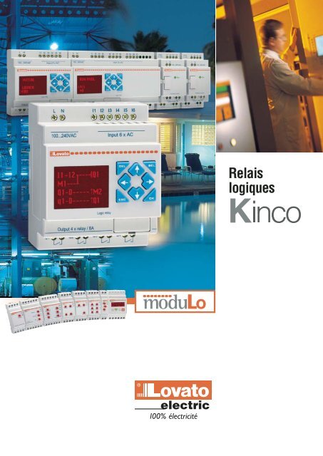
ProgrammationA tout moment et facilement, vous pouvez définir et reprogrammerpour répondre aux nouvelles exigences et améliorer lafonctionnalité du système.La programmation, facile et intuitive, peut être effectuée par lebiais du clavier du relais ou d’un ordinateur relié à travers l’interfaceLRX C00 après avoir installé le logiciel relatif (LRX SW).123456789ABCRUNMO10:31Etat entrées module de baseEtat sorties module de baseEtat LRD - jour et heureETAT E/SDATE123456789ABC19.09.051123456789ABCDEF -Etat entrées extensionEtat sorties extensionDateEtat mémoires,temporisateurs, contacteurs,RTC et comparateursana<strong>logiques</strong>TOUCHEETAT E/SETAT PLCHEURETOUCHEESCLADDER---------- 1FONCT. BLOC ---- 2RUN -------------- 3SUPPR. PROG. -- 4ECRIRE----------- 5LIRE-------------- 6MENUSET--------------- 7RTC SET --------- 8ANALOG SET ---- 9MOT DE PASSE- 10LANGUE -------- 11INITIALE-------- 12A1=1.25A2=0.00A3=2.40A4=6.59A5=5.35A6=0.10A7=2.70A8=8.32Valeur entrées ana<strong>logiques</strong>Valeur entrées ana<strong>logiques</strong>TOUCHEETAT1 Ana<strong>logiques</strong>7ID SET 01E / S D I S T A N T E NA M P O U L E xM M E M O I R E √NUMERO E / S : 0ALARME E/S:√C MEMO I RE xIl est très facile de programmer par le biais du clavier carcette opération ne requiert pas de connaissances particulières dansle domaine de la programmation.La partie avant dispose de 8 touches de fonction pour la programmation« on-board » (embarquée) et la supervision de l’état desEntrées/Sorties numériques, de la valeur des entrées ana<strong>logiques</strong>, dela date et de l’heure ainsi que de l’état de fonctionnement du relais.Les étapes de la programmation apparaissent sur l’afficheur rétroéclairécomposé de 4 lignes de 12 caractères chacune.La programmation à partir de l’ordinateur peut se faire de deuxfaçons : mode FDB (blocs de fonction) et LADDER (schéma à contacts).L’option « Simulator » permet de simuler « off-line » (hors-ligne) leprogramme directement sur l’ordinateur pour vérifier qu’il fonctionnecorrectement avant l’essai « ON-LINE » (enligne) et la mise en service.12345I1-M1----(Q1I2-Q1-m1----(T111RUN PROG .>OU INONSUPPR . PROG .>OU INONE C R I R E>OU INON10.00 T1891011RTC SET V1 . 405.09.19JUIL.13:43A1=GA IN: 010OFFSET :+00A2=GA IN: 010OFFSET :+00A3=GA IN: 010OFFSET :+00A4=GA IN: 010OFFSET :+00M O T D E P A S S E x0000ENGL I SHFRANCA I SESPANOLITALIANODEUTCHPORTUGUESCH I NESEL I R EINITIALE6>OU INON12>LADDERFDB
( )based on kernel L(·) and bandwidth g. With L nik = 1 WL i −W kg p g, letˆf i = (n−1) −1ˆr i = 1ˆfi 1(n−1)n∑k≠i,k=1n∑k≠i,k=1L nik ,so that û i = Y i − ˆr i = 1ˆfi 1(n−1)Y k L nikn∑k≠i,k=1(Y i −Y k )L nik .Denote by n (m) the number of arrangements of m distinct elements among n, and by[1/n (m) ] ∑ a, the average over these arrangements. In order to avoid random denominators,we choose ν(W) = f (W), which fulfills the assumption of Lemma 1. Then wecan estimate I(h) by the second-order U-statisticÎ n = 1 ∑ûn (2) i ˆfi û j ˆfj K nij ψ ija1 ∑∑∑=n (2) (n−1) 2 (Y i −Y k )(Y j −Y l )L nik L njl K nij ψ ij ,with K nij = 1 h p Kstatistic( )Wi −W jhak≠il≠jand ψ ij = ψ(X i −X j ). We also consider the alternativeĨ n = 1 ∑(Yn (4) i −Y k )(Y j −Y l )L nik L njl K nij ψ ij .aIt is clear that Ĩn is obtained from În by removing asymptotically negligible “diagonal”terms. Under the null hypothesis, both statistics will have the same asymptotic normaldistribution, but removing diagonal terms reduces the bias of the statistic under H 0 .Our statistics Ĩn and În are respectively similar to the ones of Fan and Li (1996) andLavergne and Vuong(2000),withthefundamentaldifferencethatthereisnosmoothingrelative to the covariates X. Indeed these authors used a multidimensional smoothingkernel over (W,X), that is h −(p+q) ˜K((Wi −W j )/h, (X i −X j )/h), while we useK nij ψ ij . For I n being either Ĩn or În, we will show that nh p/2 I nd−→N (0,ω 2 ) underH 0 and nh p/2 I np−→∞ under H 1 . By contrast, the statistics of Fan and Li (1996) andLavergne and Vuong (2000) exhibit a nh (p+q)/2 rate of convergence. The alternative5
RéférencesRéférences Alimentation ENTREES SORTIES HorodateurNumériques Numér. ou analog. (0...10VDC) ❶ NumériquesQuantité totale Quantité Quantité TypeModules de baseLRD12R D024 24VDC 6 2 4 <strong>Relais</strong> OuiLRD12T D024 24VDC 6 2 4 Transistor OuiLRD20R D024 24VDC 8 4 8 <strong>Relais</strong> OuiLRD20T D024 24VDC 8 4 8 Transistor OuiLRD12R A024 24VAC 8 0 4 <strong>Relais</strong> OuiLRD20R A024 24VAC 12 0 8 <strong>Relais</strong> OuiLRD10R A240 100 à 240VAC 6 0 4 <strong>Relais</strong> OuiLRD20R A240 100 à 240VAC 12 0 8 <strong>Relais</strong> OuiModules d’extension et de communicationLRE08R D024 24VDC 4 0 4 <strong>Relais</strong> NonLRE08T D024 24VDC 4 0 4 Transistor NonLRE08R A024 24VAC 4 0 4 <strong>Relais</strong> NonLRE08R A240 100 à 240VAC 4 0 4 <strong>Relais</strong> NonLRE P00 Module de communication protocole Modbus ®AccessoiresLRX M00Mémoire de sauvegarde du programmeLRX C00Câble de connexion PC-LRD (1,5m)LRX SWLogiciel de programmation, supervision et manuel (cd-rom)LRX 1V3 D024 Module d’alimentation 100 à 240VAC/24VDC 1,3ALRX D00Manuel d’application en italien (sur papier)LRX D01Manuel d’application en anglais (sur papier)LRX D02Manuel d’application en espagnol (sur papier)Ensembles préfabriquésLRDKIT 12R D024 Ensemble composé du relais LRD12R D024, logiciel LRX SW et câble LRX C00LRDKIT 12R A024 Ensemble composé du relais LRD12R A024, logiciel LRX SW et câble LRX C00LRDKIT 10R A240 Ensemble composé du relais LRD10R A240, logiciel LRX SW et câble LRX C00Caractéristiques techniquesAlimentation auxiliaire LRD…D024 LRD…A024 LRD…A240Tension assignée Ue (fréquence) 24VDC 24VAC 100 à 240VAC (50-60Hz)Limites de fonctionnement 20,4 à 28,8VDC - 85 à 264VACEntrées numériquesTension assignée 24VDC 24VAC 110 à 220VACTension à l’entréeSignal 0 < 5VDC / < 0.625mA ❷ < 40VAC / < 0,28mA (LRD10R A240) < 0,15mA (LRD20R A240)Signal 1 > 15VDC / > 1.875mA ❷ > 79VAC / > 0,41mATension de retardDe 0 à 1 3 à 5ms ❷ 45 à 50ms (Ue=100VAC) – 18 à 22ms (Ue=240VAC)De 1 à 0 3 à 5ms ❷ 45 à 50ms (Ue=100VAC) – 85 à 90ms (Ue=240VAC)Entrées ana<strong>logiques</strong> (seulement pour versions 24VDC)Plage du signal à l’entrée 0 à 10V - -Résolution de l’afficheur 0,01V - -Conversion 10bit - -Courant consommé à 10VDC < 0,17mA - -Impédance à l’entrée < 1kΩ - -Surcharge maxi 28VDC - -Longueur maxi du câble ≤ 30m blindé - -Sorties numériques LRD…R… / LRE08R… LRD…T… / LRE08T…Type de sortie / Courant assigné lth <strong>Relais</strong> / 8A Transistor / 0,3A 24VDCTension applicable 12 à 240VAC / 1 à 125VDC 21,6-26,4VDCConditions ambiantesTempérature de fonctionnement / stockage-20…+55°C / -40…+70°CHumidité relative20 à 90%, sans condensationDegré de pollution maximum 2BoîtierVersionModulaire pour installation sur profilé DIN 35mm (IEC/EN 60715) ou à vis (M4x15mm)Type de borneà visConnexionSection du conducteur0,75 à 3.5mm 2 / 12 AWGCouple de serrage0,4 à 0.6Nm/0,3 à 0.4lbftLongueur maxi du câble≤ 100mLRD10… / LRD12…72x106x57,3mmDimensions (lxhxp) LRD20… 126x106x57,3mmExtensions LRE…38x106x57,3mmDegré de protectionIP20Certifications et conformitéCertifications obtenues : cULus Conformes aux normes : IEC/EN 61131-2❶ Entrées numériques pouvant être aussi utilisées comme entrées ana<strong>logiques</strong>. ❷ Contactez notre bureau Service Clients (Tél 035 4282422)