Bruciatori policombustibile gasolio/gas ... - Riello Burners
Bruciatori policombustibile gasolio/gas ... - Riello Burners
Bruciatori policombustibile gasolio/gas ... - Riello Burners

You also want an ePaper? Increase the reach of your titles
YUMPU automatically turns print PDFs into web optimized ePapers that Google loves.
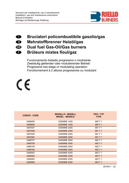
Istruzioni per installazione, uso e manutenzioneInstallation, use and maintenance instructionsManuel d’entretienMontage und Bedienungs AnleitungIDGBF<strong>Bruciatori</strong> <strong>policombustibile</strong> <strong><strong>gas</strong>olio</strong>/<strong>gas</strong>Mehrstoffbrenner Heizöl/<strong>gas</strong>Dual fuel Gas-Oil/Gas burnersBrûleurs mixtes fioul/gazFunzionamento bistadio progressivo o modulanteZweistufig gleitender oder modulierender BetriebProgressive two-stage or modulating operationFonctionnement à 2 allures progressives ou modulantCODICE - CODEMODELLO - MODELLMODEL - MODELETIPO - TYPTYPE3486655 GI/EMME 1400 680 T 13486656 GI/EMME 1400 680 T 13487657 GI/EMME 2000 681 T 13487658 GI/EMME 2000 681 T 13487659 GI/EMME 2000 681 T 13487660 GI/EMME 2000 681 T 13488757 GI/EMME 3000 682 T 13488758 GI/EMME 3000 682 T 13488759 GI/EMME 3000 682 T 13488760 GI/EMME 3000 682 T 13489063 GI/EMME 4500 683 T 13489064 GI/EMME 4500 683 T 13489065 GI/EMME 4500 683 T 13489066 GI/EMME 4500 683 T 12915611 (3)
IINDICEDINHALTDATI TECNICI. . . . . . . . . . . . . . . . . . . . . . . . . . . . .pagina 4Versioni costruttive . . . . . . . . . . . . . . . . . . . . . . . . . . . . . . .4Categorie <strong>gas</strong> . . . . . . . . . . . . . . . . . . . . . . . . . . . . . . . . . . .4Descrizione bruciatore . . . . . . . . . . . . . . . . . . . . . . . . . . . .8Ingombro . . . . . . . . . . . . . . . . . . . . . . . . . . . . . . . . . . . . . .8Corredo . . . . . . . . . . . . . . . . . . . . . . . . . . . . . . . . . . . . . . .8Campi di lavoro. . . . . . . . . . . . . . . . . . . . . . . . . . . . . . . . .10INSTALLAZIONE . . . . . . . . . . . . . . . . . . . . . . . . . . . . . . .10Piastra caldaia . . . . . . . . . . . . . . . . . . . . . . . . . . . . . . . . .10Fissaggio del bruciatore alla caldaia . . . . . . . . . . . . . . . .10Manutenzione della testa di combustione . . . . . . . . . . . .10Impianto idraulico . . . . . . . . . . . . . . . . . . . . . . . . . . . . . . .12Innesco pompa. . . . . . . . . . . . . . . . . . . . . . . . . . . . . . . . .12Potenza all’accensione del bruciatore . . . . . . . . . . . . . . .14Rampe <strong>gas</strong> . . . . . . . . . . . . . . . . . . . . . . . . . . . . . . . . . . . .14Impianto elettrico . . . . . . . . . . . . . . . . . . . . . . . . . . . . . . .17Organi del bruciatore regolati in fabbrica . . . . . . . . . . . . .22Ugelli consigliati . . . . . . . . . . . . . . . . . . . . . . . . . . . . . . . .24Variatore di pressione. . . . . . . . . . . . . . . . . . . . . . . . . . . .24Regolazione testa di combustione . . . . . . . . . . . . . . . . . .26Regolazione serranda aria . . . . . . . . . . . . . . . . . . . . . . . .28Corrente elettrica alla cellula UV . . . . . . . . . . . . . . . . . . .28Regolazioni per funzionamento a <strong>gas</strong> . . . . . . . . . . . . . . .30Sfiato dell’aria. . . . . . . . . . . . . . . . . . . . . . . . . . . . . . . . . .30Pressostato <strong>gas</strong> di minima . . . . . . . . . . . . . . . . . . . . . . . .30Pressostato <strong>gas</strong> di massima . . . . . . . . . . . . . . . . . . . . . .30Pressostato aria . . . . . . . . . . . . . . . . . . . . . . . . . . . . . . . .30Farfalla <strong>gas</strong> . . . . . . . . . . . . . . . . . . . . . . . . . . . . . . . . . . . .30Regolazione rapporto aria / <strong>gas</strong> . . . . . . . . . . . . . . . . . . . .30Funzionamento bruciatore . . . . . . . . . . . . . . . . . . . . . . . .32Difficolta’ di funzionamento e relative cause. . . . . . . . . . .32TECHNISCHE ANGABEN . . . . . . . . . . . . . . . . . . . . Seite 5Bauvarianten. . . . . . . . . . . . . . . . . . . . . . . . . . . . . . . . . . . 5Gaskategorie . . . . . . . . . . . . . . . . . . . . . . . . . . . . . . . . . . 5Brennerbeschreibung . . . . . . . . . . . . . . . . . . . . . . . . . . . . 9Abmessungen. . . . . . . . . . . . . . . . . . . . . . . . . . . . . . . . . . 9Ausstatung . . . . . . . . . . . . . . . . . . . . . . . . . . . . . . . . . . . . 9Regelbereiche. . . . . . . . . . . . . . . . . . . . . . . . . . . . . . . . . 11INSTALLATION . . . . . . . . . . . . . . . . . . . . . . . . . . . . . . . 11Kesselplatte . . . . . . . . . . . . . . . . . . . . . . . . . . . . . . . . . . 11Befestigung des Brenners am Kessel. . . . . . . . . . . . . . . 11Wartung des Flammkopfs. . . . . . . . . . . . . . . . . . . . . . . . 11Hydraulikanlage . . . . . . . . . . . . . . . . . . . . . . . . . . . . . . . 13Auffüllen der Pumpe . . . . . . . . . . . . . . . . . . . . . . . . . . . . 13Zündleistung . . . . . . . . . . . . . . . . . . . . . . . . . . . . . . . . . . 15Gasarmaturen. . . . . . . . . . . . . . . . . . . . . . . . . . . . . . . . . 15Elektroanlage . . . . . . . . . . . . . . . . . . . . . . . . . . . . . . . . . 17Im Werk eingestellte Brennerteile. . . . . . . . . . . . . . . . . . 23Empfohlene Düsen . . . . . . . . . . . . . . . . . . . . . . . . . . . . . 25Druckregler . . . . . . . . . . . . . . . . . . . . . . . . . . . . . . . . . . . 25Flammkopf - Einstellung . . . . . . . . . . . . . . . . . . . . . . . . . 27Luftklappen - Einstellung . . . . . . . . . . . . . . . . . . . . . . . . 29Stromzuführ zur UV-Zelle . . . . . . . . . . . . . . . . . . . . . . . . 29Einstellung für Gasbetrieb . . . . . . . . . . . . . . . . . . . . . . . 31Entlüftung . . . . . . . . . . . . . . . . . . . . . . . . . . . . . . . . . . . . 31Gas - Mindestdruckwächter . . . . . . . . . . . . . . . . . . . . . . 31Gas - Höchstdruckwächter . . . . . . . . . . . . . . . . . . . . . . . 31Luftdruckwächter . . . . . . . . . . . . . . . . . . . . . . . . . . . . . . 31Gasdrossel . . . . . . . . . . . . . . . . . . . . . . . . . . . . . . . . . . . 31Einstellung Luft / Gas - Verhältnis. . . . . . . . . . . . . . . . . . 31Brennerbetrieb . . . . . . . . . . . . . . . . . . . . . . . . . . . . . . . . 33Schwierigkeiten beim Anfahren und Ursachen. . . . . . . . 33GBCONTENTSFINDEXTECHNICAL DATA. . . . . . . . . . . . . . . . . . . . . . . . . . page 6Variants . . . . . . . . . . . . . . . . . . . . . . . . . . . . . . . . . . . . . . .6Gas categories . . . . . . . . . . . . . . . . . . . . . . . . . . . . . . . . . .6Burner description . . . . . . . . . . . . . . . . . . . . . . . . . . . . . . .9Max. dimensions . . . . . . . . . . . . . . . . . . . . . . . . . . . . . . . .9Standard equipment . . . . . . . . . . . . . . . . . . . . . . . . . . . . . .9Firing rates . . . . . . . . . . . . . . . . . . . . . . . . . . . . . . . . . . . .11INSTALLATION . . . . . . . . . . . . . . . . . . . . . . . . . . . . . . . .11Boiler plate . . . . . . . . . . . . . . . . . . . . . . . . . . . . . . . . . . . .11Mounting the burner on the boiler . . . . . . . . . . . . . . . . . .11Maintenance of the combustion head. . . . . . . . . . . . . . . .11Hydraulic system . . . . . . . . . . . . . . . . . . . . . . . . . . . . . . .13Pump priming . . . . . . . . . . . . . . . . . . . . . . . . . . . . . . . . . .13Firing output . . . . . . . . . . . . . . . . . . . . . . . . . . . . . . . . . . .15Gas trains . . . . . . . . . . . . . . . . . . . . . . . . . . . . . . . . . . . . .15Electrical system . . . . . . . . . . . . . . . . . . . . . . . . . . . . . . .17Factory - set burner units . . . . . . . . . . . . . . . . . . . . . . . . .23Reccomended nozzles . . . . . . . . . . . . . . . . . . . . . . . . . . .25Pressure variation. . . . . . . . . . . . . . . . . . . . . . . . . . . . . . .25Combustion head adjustment. . . . . . . . . . . . . . . . . . . . . .27Air damper adjustment . . . . . . . . . . . . . . . . . . . . . . . . . . .29Electrical current to the UV cell . . . . . . . . . . . . . . . . . . . .29Starting the burner . . . . . . . . . . . . . . . . . . . . . . . . . . . . . .31Venting the <strong>gas</strong> supply . . . . . . . . . . . . . . . . . . . . . . . . . . .31Minimum <strong>gas</strong> pressure switch . . . . . . . . . . . . . . . . . . . . .31Maximum <strong>gas</strong> pressure switch . . . . . . . . . . . . . . . . . . . . .31Air pressure switch . . . . . . . . . . . . . . . . . . . . . . . . . . . . . .31Gas butterfly . . . . . . . . . . . . . . . . . . . . . . . . . . . . . . . . . . .31Air / <strong>gas</strong> ratio adjustment . . . . . . . . . . . . . . . . . . . . . . . . .31Burner operation. . . . . . . . . . . . . . . . . . . . . . . . . . . . . . . .33Operating problems and causes. . . . . . . . . . . . . . . . . . . .33DONNÉES TECHNIQUES . . . . . . . . . . . . . . . . . . . . page 7Modéles disponibles . . . . . . . . . . . . . . . . . . . . . . . . . . . . . 7Categories gaz . . . . . . . . . . . . . . . . . . . . . . . . . . . . . . . . . 7Description brûleur . . . . . . . . . . . . . . . . . . . . . . . . . . . . . . 9Encombrement . . . . . . . . . . . . . . . . . . . . . . . . . . . . . . . . . 9Equipment standard . . . . . . . . . . . . . . . . . . . . . . . . . . . . . 9Plages de puissance. . . . . . . . . . . . . . . . . . . . . . . . . . . . 11INSTALLATION . . . . . . . . . . . . . . . . . . . . . . . . . . . . . . . 11Plaque chaudiere . . . . . . . . . . . . . . . . . . . . . . . . . . . . . . 11Fixation du Brûleur a la chaudiere . . . . . . . . . . . . . . . . . 11Entretien de la tête de combustion . . . . . . . . . . . . . . . . . 11Installation hydraulique . . . . . . . . . . . . . . . . . . . . . . . . . . 13Amorçage de la pompe. . . . . . . . . . . . . . . . . . . . . . . . . . 13Puissance a l’allumage . . . . . . . . . . . . . . . . . . . . . . . . . . 15Rampe gaz . . . . . . . . . . . . . . . . . . . . . . . . . . . . . . . . . . . 15Installation electrique . . . . . . . . . . . . . . . . . . . . . . . . . . . 17Organes du brûleur a l’usine. . . . . . . . . . . . . . . . . . . . . . 23Gicleurs conseilles . . . . . . . . . . . . . . . . . . . . . . . . . . . . . 25Variateur de pression . . . . . . . . . . . . . . . . . . . . . . . . . . . 25Réglage de la tête de combustion . . . . . . . . . . . . . . . . . 27Réglage du volet d’air . . . . . . . . . . . . . . . . . . . . . . . . . . . 29Courant électrique a la cellule UV . . . . . . . . . . . . . . . . . 29Réglage pour fonctionnement au gaz. . . . . . . . . . . . . . . 31Evacuation de l’air . . . . . . . . . . . . . . . . . . . . . . . . . . . . . 31Pressostat gaz seiul minimum . . . . . . . . . . . . . . . . . . . . 31Pressostat gaz maxi. . . . . . . . . . . . . . . . . . . . . . . . . . . . 31Pressostat de l’air . . . . . . . . . . . . . . . . . . . . . . . . . . . . . . 31Papillon gaz . . . . . . . . . . . . . . . . . . . . . . . . . . . . . . . . . . 31Réglage rapport air / gaz . . . . . . . . . . . . . . . . . . . . . . . . 31Fonctionnement brûleur . . . . . . . . . . . . . . . . . . . . . . . . . 33Difficultes de fonctionnement et cause . . . . . . . . . . . . . . 333
DATI TECNICIIMODELLO GI/EMME 1400 GI/EMME 2000 GI/EMME 3000 GI/EMME 4500TIPO 680 T1 681 T1 682 T1 683 T1POTENZA(1) Pressione minima (misurata al manicotto) con camera di combustione a 0 bar per avere la massima potenzialità.(2) Il modello GI/EMME 4500 è previsto solo nella versione con teleavviatore stella - triangolo; all’atto dell’ordine deve quindiessere specificata la prevista tensione di funzionamento.VERSIONI COSTRUTTIVEMin. dimodul.Min. difunz.Max. difunz.Kcal/h 350.000 500.000 750.000 1.000.000kW 407 581 872 1.163Kcal/h 705.000 1.000.000 1.500.000 2.021.000kW 820 1.163 1.744 2.350Kcal/h 1.325.000 2.000.000 3.000.000 4.000.000kW 1.540 2.325 3.488 4.650COMBUSTIBILEMetano: 8 - 10 kWh/Nm 3Gasolio: viscosità max. a 20°C 6 cSt (1,5°E)PRESSIONE MASSIMA mbar 200 360 360 360PRESSIONE MINIMA (1) mbar 20 26 33 43ALIMENTAZIONEELETTRICA (2)Trifase 230 V +/- 10% 50 Hz 400V +/- 10% 50 HzPOTENZA ELETTRICA MOTORI kW 3 + 1,1 4 + 1,1 9 + 1,5 12 + 1,5APPARECCHIATURA ELETTRICA LANDIS & GYR LFL 1.333TRASFORMATORE DI ACCEN-35 mA 2 x 6000V - 1,9 A a 230VSIONECONFORMITÀ DIRETTIVE CEE 90/396 - 89/336 - 73/23PESO Kg 190 235 280 285OMOLOGAZIONE CE 0085AQ0712OMOLOGAZIONE DIN 5G830/97 M 5G831/97 M 5G832/97 M 5G833/97 MMODELLOCodicealimentazioneelettrica trifaselunghezzaboccaglio mmMotoreGI/EMME 140034866553486656230 - 400N230 - 400N385495avviamento direttoavviamento direttoGI/EMME 20003487657348765834876593487660230 - 400N230 - 400N400N400N385495385495avviamento direttoavviamento direttoavviamento stella-triangoloavviamento stella-triangoloGI/EMME 30003488757348875834887593488760230 - 400N230 - 400N400N400N476606476606avviamento direttoavviamento direttoavviamento stella-triangoloavviamento stella-triangoloGI/EMME 45003489063348906434890653489066230230400N400N476606476606avviamento stella-triangoloavviamento stella-triangoloavviamento stella-triangoloavviamento stella-triangoloCATEGORIE GASPAESECATEGORIASE - FI - AT - GR - DK - ES - GB - IT - IE - PTDENLFRBELUI 2HI 2ELLI 2LI 2ErI 2E(R)BI 2EImportante:L’installatore è responsabile per l’eventuale aggiunta di organi di sicurezza non previsti in questo manuale.4
TECHNISCHE ANGABENDMODELL GI/EMME 1400 GI/EMME 2000 GI/EMME 3000 GI/EMME 4500TYP 680 T1 681 T1 682 T1 683 T1LEISTUNG(1) Minimaldruck (an der Muffe), bei druckloser Brennkammer.(2) Das Modell GI/EMME 4500 steht nur in der Ausführung mit Stern-Dreieck-Anlauf zur Verfügung; bei Bestellung muß dievorgesehene Betriebsspannung angegeben werden.BAUVARIANTENMindestmodulierungBetrieb - Mind.Betrieb - Höchstl.Kcal/h 350.000 500.000 750.000 1.000.000kW 407 581 872 1.163Kcal/h 705.000 1.000.000 1.500.000 2.021.000kW 820 1.163 1.744 2.350Kcal/h 1.325.000 2.000.000 3.000.000 4.000.000kW 1.540 2.325 3.488 4.650BRENNSTOFFErd<strong>gas</strong> G 20 Hu 10 kWh/Nm 3 - G 25 Hu 8,6 kWh/Nm 3Heizöl EL max Viskosität 20° C: cSt (1,5° E)HÖCHSTDRUCK mbar 200 360 360 360MINDESTDRUCK (1) mbar 20 26 33 43ELEKTRISCHE VERSORGUNG (2) Dreiphasing 230 V +/- 10% 50 Hz 400V +/- 10% 50 HzELEKTRISCHE LEISTUNGMOTORENkW 3 + 1,1 4 + 1,1 9 + 1,5 12 + 1,5FEUERUNGSAUTOMATIC LANDIS & GYR LFL 1.333ZÜNDTRAFO35 mA 2 x 6000V - 1,9 A a 230VCE-NORMGERECHT 90/396 - 89/336 - 73/23GEWICHT Kg 190 235 280 285TYPPRÜFUNG CE 0085AQ0712TYPPRÜFUNG DIN 5G830/97 M 5G831/97 M 5G832/97 M 5G833/97 MMODELLCodeElektrischeSpannung DrehstromFlammrohrLänge mmMotorGI/EMME 140034866553486656230 - 400N230 - 400N385495DirektschaltungDirektschaltungGI/EMME 20003487657348765834876593487660230 - 400N230 - 400N400N400N385495385495DirektschaltungDirektschaltungStern-Dreieck SchaltungStern-Dreieck SchaltungGI/EMME 30003488757348875834887593488760230 - 400N230 - 400N400N400N476606476606DirektschaltungDirektschaltungStern-Dreieck SchaltungStern-Dreieck SchaltungGI/EMME 45003489063348906434890653489066230230400N400N476606476606Stern-Dreieck SchaltungStern-Dreieck SchaltungStern-Dreieck SchaltungStern-Dreieck SchaltungGASKATEGORIELANDSE - FI - AT - GR - DK - ES - GB - IT - IE - PTDENLFRBELUKATEGORIEI 2HI 2ELLI 2LI 2ErI 2E(R)BI 2EWichtiger Hinweis:Der Installateur haftet für den eventuellen Zusatz von Sicherheitsteilen, die nicht in dieser Betriebsanleitung vorgesehen sind.5
TECHNICAL DATAGBMODEL GI/EMME 1400 GI/EMME 2000 GI/EMME 3000 GI/EMME 4500TYPE 680 T1 681 T1 682 T1 683 T1OUTPUT1) Minimum pressure (measured at the sleeve) with the combustion chamber at 0 bar to obtain maximum output.2) The GI/EMME 4500 model is only available in version with a star - triangle remote - starter; when opering, please thereforespecify the required operating voltage.VARIANTSMin. modulationMin. operationMax. operationKcal/h 350.000 500.000 750.000 1.000.000kW 407 581 872 1.163Kcal/h 705.000 1.000.000 1.500.000 2.021.000kW 820 1.163 1.744 2.350Kcal/h 1.325.000 2.000.000 3.000.000 4.000.000kW 1.540 2.325 3.488 4.650FUELNatural <strong>gas</strong>: Pci 8 - 10 kWh/Nm 3Gasoil: max. viscosity at 20°C 6 cSt (1,5°E)MAXIMUM PRESSURE mbar 200 360 360 360MINIMUM PRESSURE (1) mbar 20 26 33 43ELECTRICAL POWER SUPPLY (2) Three phase 230 V +/- 10% 50 Hz 400V +/- 10% 50 HzELECTRICAL OUTPUT MOTORS kW 3 + 1,1 4 + 1,1 9 + 1,5 12 + 1,5CONTROL BOX LANDIS & GYR LFL 1.333IGNITION TRANSFORMER35 mA 2 x 6000V - 1,9 A a 230VIN CONFORMITY WITH EEC DIRECTIVES 90/396 - 89/336 - 73/23WEIGHT Kg 190 235 280 285APPROVAL CE 0085AQ0712APPROVAL DIN 5G830/97 M 5G831/97 M 5G832/97 M 5G833/97 MMODELCodeElectrical supplythree phaseblast tubelength mmMotorGI/EMME 140034866553486656230 - 400N230 - 400N385495direct startingdirect startingGI/EMME 20003487657348765834876593487660230 - 400N230 - 400N400N400N385495385495direct startingdirect startingstar-delta startingstar-delta startingGI/EMME 30003488757348875834887593488760230 - 400N230 - 400N400N400N476606476606direct startingdirect startingstar-delta startingstar-delta startingGI/EMME 45003489063348906434890653489066230230400N400N476606476606star-delta startingstar-delta startingstar-delta startingstar-delta startingGAS CATEGORIESCOUNTRYSE - FI - AT - GR - DK - ES - GB - IT - IE - PTDENLFRBELUCATEGORYI 2HI 2ELLI 2LI 2ErI 2E(R)BI 2EImportant:The installer is responsible for the addition of any safety device not forseen in the present manual.6
DONNEES TECHNIQUESFMODELE GI/EMME 1400 GI/EMME 2000 GI/EMME 3000 GI/EMME 4500TYPE 680 T1 681 T1 682 T1 683 T1PUISSANCEMini. de modul.Mini. de fonc.Maxi. de fonc.1) Pression minimum (misureé au manchon) avec cambre de combustion à 0 mbar pour avoir la puissance maximum.2) Le modèle GI/EMME 4500 est prévu uniquement das la version démarreur étoile - triangle; la tension de fonctionnement doitêtre spécifiée au moment de la commande.MODELES DISPONIBLESKcal/h 350.000 500.000 750.000 1.000.000kW 407 581 872 1.163Kcal/h 705.000 1.000.000 1.500.000 2.021.000kW 820 1.163 1.744 2.350Kcal/h 1.325.000 2.000.000 3.000.000 4.000.000kW 1.540 2.325 3.488 4.650COMBUSTIBLEGaz naturel: 8 - 10 kWh/Nm 3Fioul domestique max viscosité at 20° C: 6 cSt (1,5° E)PRESSION MAXI mbar 200 360 360 360PRESSION MINI mbar (1) 20 26 33 43ALIMENTATION ELECTRIQUE (2) Trifase 230 V +/- 10% 50 Hz 400V +/- 10% 50 HzPUISSANCE ELECTRIQUEMOTEURSkW 3 + 1,1 4 + 1,1 9 + 1,5 12 + 1,5BOITE DE CONTRÔLE LANDIS & GYR LFL 1.333TRASFORMATEUR ALLUMAGE35 mA 2 x 6000V - 1,9 A a 230VCONFORMÉMENT AUX DIRECTIVES CEE 90/396 - 89/336 - 73/23POIDS Kg 190 235 280 285HOMOLOGATION CE 0085AQ0712HOMOLOGATION DIN 5G830/97 M 5G831/97 M 5G832/97 M 5G833/97 MMODELECodealimentationélectrique triphaséelongueurbuse mmMoteurGI/EMME 140034866553486656230 - 400N230 - 400N385495démarrage directdémarrage directGI/EMME 20003487657348765834876593487660230 - 400N230 - 400N400N400N385495385495démarrage directdémarrage directdémarrage étoile-triangledémarrage étoile-triangleGI/EMME 30003488757348875834887593488760230 - 400N230 - 400N400N400N476606476606démarrage directdémarrage directdémarrage étoile-triangledémarrage étoile-triangleGI/EMME 45003489063348906434890653489066230230400N400N476606476606démarrage étoile-triangledémarrage étoile-triangledémarrage étoile-triangledémarrage étoile-triangleCATEGORIES GAZPAYSSE - FI - AT - GR - DK - ES - GB - IT - IE - PTDENLFRBELUCATEGORIEI 2HI 2ELLI 2LI 2ErI 2E(R)BI 2EAttention:Si l’installateur ajoute des organes de sécurité non prévus dans ce manuel, il en assume la responsabilité.7
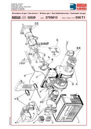
D1379D1372DESCRIZIONE BRUCIATORE (A)1 Modulatore di potenza(solo per versione modulante)2 Pressostato aria3 Asta comando farfalla <strong>gas</strong>4 Blocco relè motore ventilatore5 Morsettiera6 Passacavi7 Pulsante di sblocco apparecchiaturacon segnalazione di blocco8 Asta di trascinamento testa9 Servomotore10 Camma di regolazione aria11 Pressostato <strong>gas</strong> di massima12 Presa di pressione <strong>gas</strong> al manicotto13 Regolatore <strong>gas</strong>14 Eccentrico regolazione pressioneritorno15 Pressostato olio max.16 Manometro pressione sul ritorno17 Manometro pressione in mandata18 Quadro comandi elettrici19 Trasformatore d’accensione20 Gruppo pompante21 Camma di regolazione22 Commutatore olio - <strong>gas</strong>23 Regolatore di pressione24 Attacco di aspirazione25 Attacco di ritorno26 Attacco di mandata27 Attacco vacuometro28 Attacco manometro29 Pressostato olio di min.Pompa - Pumpe - Pump - Pompe:SAFAG(A)Pompa - Pumpe - Pump - Pompe:SUNTEC• Lo sblocco relè motore per versioni conavviatore si trova all’interno dellostesso.• Lo sblocco relè motore pompa si trovaall’interno della scatola a fianco delgruppo pompante.INGOMBRO (B) - (Misure indicative)L'ingombro del bruciatore è riportato nellafig. (B).L2 Lunghezza boccaglio testa corta +distanzialeL2* Lunghezza boccaglio testa cortaL2** Lunghezza boccaglio testa lungaD1373(B)TIPO A1 A2 L1 L2 L2* L2** H1 H2GI/EMME 1400 482 376 1090 275 385 495 250 467GI/EMME 2000 482 396 1090 275 385 495 260 467CORREDO1 - Flangia (per GI/EMME 1400)1 - Guarnizione per armatura8 - Viti (per GI/EMME 1400)12 - Viti2 - Prolunghe1 - Schermo isolante2 - Tubi flessibili2 - Nipples4 - Passacavi8 - Rosette (per GI/EMME 1400)12 - RosetteGI/EMME 3000 538 447 1320 346 476 606 336 525GI/EMME 4500 538 508 1320 346 476 606 336 5258
BRENNERBESCHREIBUNG (A)1 Leistungsmodulator(nur bei modulierendem Betrieb)2 Luftdruckwächter3 Steuergestänge Gasdrossel4 Relais - Entriegelung Gebläsemotor5 Klemmleiste6 Kabeldruchgang7 Entriegelungsdruckknopf mit Störungsmeldung8 Flammkopf - Mitnehmer9 Stellmotor10 Lufteinstellnocken11 Gashöchstdruckwächter12 Gasdruckanschluß an Verbindungsrohr13 Gasdrossel14 Druck - Einstellnocken Rücklauf15 Öldruckwächter max.16 Druckmanometer Rücklauf17 Druckmanometer Vorlauf18 Steuerschalttafel19 Zündtransformator20 Pumpeinheit21 Gas - Einstellnocken22 Öl - Gas - Umschalter23 Druckregler24 Sauganschluß25 Anschluß Rücklauf26 Anschluß Vorlauf27 Vakuummeter - Anschluß28 Manometer - Anschluß29 Öldruckwächter min.• Das Motor - Entriegellungstaste fürModelle mit Stern - Dreieck Starterbefindet sich innerhalb des Starter.• Das Entriegelungsrelais des Pumpenmotorsbefindet sich im Gëhause nebender Pumpeneinheit.ABMESSUNGEN (B) - (Richtwerte)Die Brennerabmessungen sind in der Abb.(B) angeführt.L2Länge Flammenrohr kurzer Flammkopf+ DistanzstückL2* Länge Flammenrohr kurzer FlammkopfL2** Länge Flammenrohr langer FlammkopfAUSSTATUNG1 - Flansch (für GI/EMME 1400)1 - Stck Dichtung für Armatur8 - Stck Schrauben (für GI/EMME 1400)12 - Stck Schrauben2 - Stck Stiftverlängerung1 - Stck Isolierschutz2 - Stck Schlauch2 - Stck Nippel4 - Stck Kabeldurchgang8 - Stck Unterlegscheiben(für GI/EMME 1400)12 - Stck UnterlegscheibenBURNER DESCRIPTION (A)1 Output modulation unit(only on modulating version)2 Air pressure switch3 Gas butterfly control rod4 Fan motor relay releaser5 Terminal strip6 Fair lead7 Control box release pushbutton withlock signal8 Head drive rod9 Servomotor10 Air adjustment cam11 Max. <strong>gas</strong> pressure switch12 Gas pressure socket to sleeve13 Gas regulator14 Return pressure adjustment cam15 Oil pressure switch (max.)16 Pressure gauge on return17 Pressure gauge on delivery18 Electrical control board19 Ignition transformer20 Pump unit21 Gas adjustment cam22 Oil - <strong>gas</strong> selector switch23 Pressure regulator24 Inlet fitting25 Return fitting26 Delivery fitting27 Vacuum - meter fitting28 Pressure gauge fitting29 Oil pressure switch (min.)• The fan motor relay releaser for modelswith starter is located inside the starter.• The pump motor relay releaser islocated inside the box to the side of thepump unit.MAX. DIMENSIONS (B)(Approximate measurements)The maximum dimensions of the burnerare given in fig. (B).L2 Tube length, short head + spacerL2* Tube length, short headL2** Tube length, long headSTANDARD EQUIPMENT1 - Gas train <strong>gas</strong>ket (for GI/EMME 1400)1 - Gas train <strong>gas</strong>ket8 - Screws (for GI/EMME 1400)12 - Screws2 - Pin extension1 - Insulating screen2 - Hoses2 - Nipples4 - Fair leads8 - Washers (for GI/EMME 1400)12 - WashersDESCRIPTION BRULEUR (A)1 Regulateur de puissance(uniquement pour version modulante)2 Pressostat air3 Tige de commande papillon gaz4 Rearmement relais moteur ventilateur5 Bornier6 Presse etoupes7 Bouton de rearmement boîtier segnalisationde verrouillage8 Tige d’entraînement tête9 Servomoteur10 Came de réglage air11 Pressostat gaz maxi12 Prise de pression gaz au manchon13 Variateur débit14 Excentrique réglage15 Pressostat fioul max.16 Manomètre pression sur return17 Manomètre pression en arrivée18 Panel électrique19 Trasformateur d’allumage20 Groupe pompe21 Came de réglage gaz22 Commutateur fioul - gaz23 Régulateur de pression24 Prise d’aspiration25 Prise de retour26 Prise de refoulement27 Prise vacuomètre28 Prise manomètre29 Pressostat fioul min.• Le rearmement relais moteur pour lesmodèles avec démarreurs se trouve àl’intérieur du même.• Le rearmement realis moteur pompe setrouve à l’intérieur de le bôite placée àcôte du group pompe.ENCOMBREMENT (B)(Mesures indicatives)L'encombrement du brûleur est indiquédans le tab. (B).L2 Longeur tête courte + entretoiseL2* Longeur tête courteL2** Longeur tête longueEQUIPEMENT STANDARD1 - Flange (pour GI/EMME 1400)1 - Garniture pour armature8 - Vis (pour GI/EMME 1400)12 - Vis2 - Rallonge pour axe1 - Ecran isolant2 - Tubes flexibles2 - Attaches4 - Passe - câble8 - Rondelles (pour GI/EMME 1400)12 - Rondelles9
Pressione / Druck mbarPressure / Pression(A)mm A B CGI/EMME 1400 255 260 M 16GI/EMME 2000 265 260 M 16GI/EMME 3000 340 310 M 20GI/EMME 4500 340 310 M 20(B)(C)D1366D1375D1374CAMPI DI LAVORO (A)Il CAMPO DI LAVORO è stato ricavato allatemperatura ambiente di 20 °C ed alla pressionebarometrica di 1000 mbar (circa 100 ms.l.m.).INSTALLAZIONEPIASTRA CALDAIA (B)Forare la piastra di chiusura della cameradi combustione come in (B). La posizionedei fori filettati può essere tracciata utilizzandolo schermo termico a corredo delbruciatore.FISSAGGIO DEL BRUCIATORE ALLACALDAIA (C)Per separare il bruciatore dalla testa dicombustione procedere come segue:- Togliere il coperchio dalla mensola 1), ilperno 2), i fermi 4) e le viti 3).- Staccare le tubazioni 6).- Sganciare il tirante della farfalla <strong>gas</strong>togliendo la vite 11).- Sfilare il bruciatore dalla testa di combustioneper circa 100 ÷ 120 mm e sganciarela forcella di trascinamento 7)togliendo le viti 10).- A questo punto è possibile sfilare completamenteil bruciatore dai perni 5).- Fissare il boccaglio alla caldaia interponendolo schermo isolante 9).- Infilare il bruciatore sui perni 5) lasciandoloaperto per circa 100 ÷ 120 mm.- Rimontare la forcella 7) agganciandolacon le viti 10).- Chiudere completamente il bruciatore fissandolocon le viti 3), montare i fermi 4), ilperno con copiglia 2), il tirante della farfalladel <strong>gas</strong> 11) e le tubazioni 6).- A bruciatore aperto è possibile separareil manicotto <strong>gas</strong> 8) dal boccaglio.- Prima di montare il bruciatore sulla caldaiaè consigliabile montare l’ugellocome più avanti specificato.NOTASollevando il bruciatore per mezzo deiganci è possibile fissarlo alla caldaia senzasepararlo dalla testa di combustione.MANUTENZIONE DELLA TESTA DICOMBUSTIONE- Ripetere le operazioni sopra descritteservendosi delle apposite prolunghe,per i perni 5), fornite a corredo.- Nell’apertura del bruciatore si raccomandadi sostenerne il peso con mezziadeguati o tramite l’apposito supporto aruote fornito su richiesta.10
REGELBEREICHE (A)Der REGELBEREICH wurde bei einerRaumtemperatur von 20 °C und einembarometrischen Druck von 1000 mbar(ungefähr 100 m ü.d.M.) gemessen.INSTALLATIONKESSELPLATTE (B)Die Abdeckplatte der Brennkammer wie in(B) gezeigt vorbohren. Die Position derGewindebohrungen kann mit dem zurGrundausstattunggehörendenWärmeschild ermittelt werden.BEFESTIGUNG DES BRENNERS AMKESSELUm den Brenner vom Flammkopf zu trennenfolgendermaßen vorgehen:- Abdeckung von der Konsole 1), Stift 2),Feststellvorrichtungen 4) und Schrauben3) abnehmen.- Leitungen 6) abnehmen.- Gasdrosselgestänge aushängen, dazuSchraube 11) entfernen.- Den Brenner um ca 100 ÷ 120 mm ausdem Flammkopf herausziehen und dieMitnehmergabel 7) aushängen, wozudie Schrauben 10) entfernt werdenmüssen.- Nun kann der Brenner vollständig anden Führungsstiften 5) herausgezogenwerden.- Das Flammenrohr am Kessel befestigen,dabei Isolierschutz 9) dazwischenlegen.- Den Brenner auf die Führungstifte 5)setzen, nicht ganz einschwenken, sonderneine Öffnung von 100 ÷ 120 mmbelassen.- Die Mitnehmergabel 7) wieder einsetzenund mit den Schrauben 10) befestigen.- Den Brenner ganz einschwenken, mitden Schrauben 3) befestigen, die Feststellvorrichtungen4), den Stift mit Splint2), das Zuggestänge der Gasdrossel11), die Leitungen 6) anbringen.- Bei ausgeschwenktem Brenner kannder Verbindungsrohr 8) vom Flammenrohrgetrennt werden.- Bevor der Brenner am Kessel befestigtwird, ist es ratsam, die Düse nach nachstehendenAnleitungen zu montieren.VERMERKWenn man den Brenner mit den Hakenhochhebt, kann er am Kessel angebrachtwerden, ohne den Flammkopf abnehmenzu müssen.WARTUNG DES FLAMMKOPFS- Oben beschriebene Vorgänge wiederholen,die Verlängerungen für die mitgeliefertenStifte 5) benützen.- Beim Ausschwenken des Brenners mitgeeigneten Hilfsmitteln das Gewichtabstützen oder die unterfahrbare, aufWunsch lieferbare Unterlage einsetzen.FIRING RATES (A)The FIRING RATE area values have beenobtained considering a surrounding temperatureof 20°C and an atmospheric pressureof 1000 mbar (approx. 100 m abovesea level).INSTALLATIONBOILER PLATE (B)Drill the combustion chamber locking plateas shown in (B). The position of thethreaded holes can be marked using thethermal screen supplied with the burner.MOUNTING THE BURNER ON THEBOILER (C)To detach the burner from the combustionhead, proceed as follows:- Remove the cover from bracket 1), pin 2),stops 4) and screws 3).- Detach hoses 6).- Release the tie-rod on the <strong>gas</strong> butterfly,removing screw 11).- Slide the burner out of the combustionhead by about 100 ÷ 120 mm, andrelease the drive fork 7) by removingscrews 10).- It is now possible to slide the burnerfully out on pins 5).- Secure the tube to the boiler, insertingthe insulating screen 9).- Slide the burner in on pins 5), leaving itopen by about 100 ÷ 120 mm.- Refit fork 7), securing it with screws 10).- Completely close the burner, securing itwith screws 3), fit stops 4), pin with cotter2), <strong>gas</strong> butterfly tie-rod 11), andhoses 6).- When the burner is open, it is possibleto detach <strong>gas</strong> sleeve 8) from the tube.- Before fitting the burner to the boiler, itis advisable to fit the tube as specifiedbelow.NOTEBy lifting the burner with hooks, it is possibleto secure it to the boiler without detachingit from the combustion head.MAINTENANCE OF THE COMBUSTIONHEAD- Repeat the operations described aboveusing the special extensions for pins 5)supplied as standard with the system.- When opening the burner, it is advisableto support its weight by suitable meansor using the wheeled support unit availableon request.PLAGES DE PUISSANCE (A)La PLAGE DE PUISSANCE a été calculéeà une température ambiante de 20 °C et àune pression barométrique de 1000mbars (environ 100 m au - dessus duniveau de la mer).INSTALLATIONPLAQUE CHAUDIERE (B)Percer la plaque de fermeture de la chambrede combustion comme sur la fig. (B).La position des trous filetés peut être tracéeen utilisant l'écran thermique fourniavec le brûleur.FIXATION DU BRULEUR A LA CHAU-DIERE (C)Pour séparer le brûleur de la tête de combustion,procéder comme suit:- Enlever le couvercle du support 1), l’axe2), les arrêts 4) et les vis 3).- Détacher les tubes 6).- Détacher le tirant du papillon gaz enenlevant les vis 11).- Reculer le brûleur de la tête de combustionde 100 ÷ 120 mm environ et détacherla fourche d’entraînement 7) enenlevant les vis 10).- Il est possible à ce point d’enlever complètementle brûleur de ses guides 5).- Fixer la tête du brûleur à la chaudièreen intercalant l’écran isolant 9).- Replacer le brûleur sur ses guides 5) enle laissant à une distance de 100 ÷ 120mm environ.- Remonter le petite fourche 7) et la fixeravec les vis 10).- Refermer complètement le brûleur en lefixant avec les vis 3), monter les arrêts4), l’axe et la goupille 2), le tirant dupapillon gaz 11), les tubes 6).- Lorsque le brûleur est ouvert, il est possiblede séparer le manchon gaz 8) dela tête du brûleur.- Avant de monter le brûleur sur la chaudière,il est conseillé de monter legicleur comme indiqué ci - dessous.NOTEEn soulevant le brûleur avec des crochets,il est possible de le fixer à la chaudièresans le séparer de la téte.ENTRETIEN DE LA TÊTE DE COMBUS-TION- Répéter les opération décrites ci - dessusen se servant des rallonges spéciales,pour les guides 5) qui sont fournies.- Lors de l’ouverture de brûleur, il estrecommandé de soutenir le poids avecdes moyens appropriés ou avec le supportà roues spécial fourni surdemande.11
IMPIANTO IDRAULICOATTENZIONE:Accertarsi, prima di mettere in funzionamentoil bruciatore, che il tubo diritorno non abbia occlusioni. Un impedimentoprovocherebbe la rotturadell’organo di tenuta della pompa.(A)D1376G/M 1400 2000 3000 4500L mHØi Øi Øi Øi Øi Øi Øi Øim14 16 16 18 G 1/2” G 3/4” G 3/4” G 1”+ 2,0 55 70 40 60 25 85 55 130+ 1,5 45 65 35 55 23 80 50 120+ 1,0 40 60 30 50 20 70 45 110+ 0,5 35 50 25 45 18 65 40 1000 30 45 20 40 15 60 35 90- 0,5 25 40 18 35 12 50 30 80- 1,0 20 35 15 30 10 45 25 70- 1,5 15 30 13 25 8 35 20 60- 2,0 10 25 10 20 5 30 15 45- 3,0 5 15 5 10 3 15 10 25Non si deve superare la depressione max.di 0,45 bar (35 cm Hg). Oltre tale valore siha liberazione di <strong>gas</strong> dal combustibile.Si raccomanda che le tubazioni siano aperfetta tenuta.Quando la cisterna è ad un livello inferioreal bruciatore, si consiglia di far arrivare latubazione di ritorno alla stessa altezzadella tubazione di aspirazione.In questo caso non è necessaria la valvoladi fondo.Se la tubazione di ritorno arriva sopra illivello del combustibile la valvola di fondo èindispensabile. Questa soluzione è menosicura della precedente per la possibilemancanza di tenuta della valvola.LEGENDA (A)H = DislivelloL = Lunghezza totale della tubazioneØi = Diametro interno del tubo.I tubi in rame con Øi 14 e 16 mm possonoessere sostituiti con tubazioni inacciaio da G 1/2” e G 3/4”.INNESCO POMPARiempire la pompa di <strong><strong>gas</strong>olio</strong> dall’attaccodel vacuometro 27)(A)p.8.Avviare il bruciatore, sfiatare l’ariadall’attacco manometro 28)(A)p.8 ed attenderel’innesco della pompa.Se avviene il blocco ripetere l’operazione.12
HYDRAULIKANLAGEACHTUNG:Vor Inbetriebnahme des Brennersnachprüfen, dass das Rückflussrohrnicht verstopft ist.Eventuelle Behinderungen würden dieWellendichtung der Pumpe beschädigen.Das max. Vakuum vom 0,45 bar (35 cm Hg)darf nicht überschritten werden.Über diesem Wert bilden sich Brennstoff<strong>gas</strong>e.Sich vergewissern, dass die Leitungenabsolut dicht sind.Wenn der Tank tiefer als der Brennerangebracht ist, empfehlen wir, dieRücklaufleitung in gleicher Höhe wie dieder Saugleitung enden zu lassen.In diesem Fall ist ein Fussventil überflüssig.Sollte die Rücklaufleitung über demNiveau des Brennstoffes enden, ist einFussventil unerlässlich.Diese Lösung ist aufgrund einer möglichenUndichtheit des Ventiles nicht so sicherwie die vorher beschriebene.ZEICHENERKLÄRUNG (A)H = HöhenunterschiedL = Gesamtlänge des Ausgangsschlauches.Øi = Innerer Durchmesser des Schlauches.Kupferrohre mit Ø 14 und 16mm können mit Stahlrohren G 1/2”und G 3/4” ersetzt werden.AUFFÜLLEN DER PUMPEDie Pumpe am Vakuummeteranschluss27)(A)S. 8 auffüllen. Den Brenner starten,die Luft am Manometer ablassen 28(A)S. 8und warten, bis die Pumpe aufgefüllt ist.Sollte eine Störabschaltung erfolgen, mussder Vorgang wiederholt werden.HYDRAULIC SYSTEMIMPORTANT:Before placing the burner in operation,ensure that the return line is open.Any obstruction may damage the pumpseal.Pay attention to do not overcome the max.depression of 0,45 bar (35 cm Hg), overthis value the fuel may turn into <strong>gas</strong>.Check the pipes are perfectly sealed.When the fuel tank is under the burnerlevel we suggest to let the return line arrivewhere the suction line starts. In this casethe foot valve is not necessary.Should the return line arrive over the fuellevel, the foot valve is indispensable.Notice that this solution is less safe thanthe previous one, because it is possiblethe valve has not a good sealing.KEY (A)H = Difference in the pipes height.L = Total lenght of the suction tube.Øi = Internal diameter of the tube.Copper tubes Ø 14 and 16 mm couldbe replaced by steel tubes G 1/2” andG 3/4”.PUMP PRIMINGFill the pump with the light oil from thevacuometer plug 27)(A)p. 8, put the burnerin operation, purge the air from the manometerplug 28)(A)p. 8 and wait for thepump priming. If lock-out occurs repeat theprocedure.INSTALLATION HYDRAULIQUEATTENTION:S’assurer, avant de mettre en route lebrûleur, que le tube de retour ne soitpas obstrué.Une obturation éventuelle provoqueraitla rupture de l’organe d’étanchéité de lapompe.Ne pas dépasser la depression max. de0,45 bar (35 cm Hg).Au-dessus de cette valeur se crée la séparationdu gaz du combustible.Les tuyauteries doivent être parfaitementétanches.Quand la curve est à un niveau inférieur àcelui du brûleur, il est conseillé d’amenerla tuyauterie du retour au même niveauque la tuyauterie d’aspiration.Dans ce cas, le clapet crépine n’est pasune obligation.Si la tuyauterie de retour arrive au-dessusdu niveau du combustible, le clapetcrépine est indispensable.Cette solution est moins sûre que la précédenteà cause, éventuellement, de lamauvaise étanchéité du clapet crépine.LEGENDE (A)H = DenivellationL = Longueur totale du tube d’aspiration.Øi = Diamètre interne de la tuyauteries.Les tuyauteries en cuivre de Ø 14 et16 mm peuvent être remplacées pardes tuyauteries en acier de G 1/2” etG 3/4”.AMORÇAGE DE LA POMPERemplir de fuel la pompe par le raccordvacuomètre 27)(A)p. 8, mettre en ruote lebrûleur, purger l’air par le raccord dumanomètre 28)(A)p. 8 et attendre la sortiedu fuel. Si une mise en sécurité intervient,répéter l’opération.13
mbarmbarG 20 G 25GI/EMME 1400RAMPA L - GASARMATUREN LGAS TRAIN L - RAMPE GAZ LGI/EMME 2000GI/EMME 3000GI/EMME 4500AttaccoAnschlußConnectionRaccordCOMPONENTI - KOMPONENTENCOMPONENTS - COMPOSANTS∆p mbar13Ø COD.5 6 8 - 9820 kW 1200 kW 1540 kW2” 3970160 13,0 28,0 40,0 2” - GF 520/1 FRS 520 DMV - DLE 520/112” 3970182 13,0 23,0 35,0 2” - Multiblock MB DLE 420DN 65 3970161 5,0 10,0 15,0 2” 3000825 GF 40065/3 FRS 5065 DMV - DLE 5065/11DN 80 3970162 - 5,5 8,0 2” 3000826 GF 40080/3 FRS 5080 DMV - DLE 5080/11RAMPA L - GASARMATUREN LGAS TRAIN L - RAMPE GAZ LAttaccoAnschlußConnectionRaccordCOMPONENTI - KOMPONENTENCOMPONENTS - COMPOSANTS∆p mbar13Ø COD.5 6 8 - 91160 kW 1800 kW 2325 kW2” 3970160 24,0 58,0 85,0 DN 80 3010128 GF 520/1 FRS 520 DMV - DLE 520/112” 3970182 20,0 42,0 75,0 DN 80 3010128 Multiblock MB DLE 420DN 65 3970161 9,0 21,0 32,0 DN 80 3000831 GF 40065/3 FRS 5065 DMV - DLE 5065/11DN 80 3970162 - 11,0 16,0 DN 80 3000832 GF 40080/3 FRS 5080 DMV - DLE 5080/11DN 100 3970163 - 5,0 7,5 DN 80 3010127 GF 40100/3 FRS 5100 DMV - DLE 5100/11RAMPA L - GASARMATUREN LGAS TRAIN L - RAMPE GAZ LAttaccoAnschlußConnectionRaccordCOMPONENTI - KOMPONENTENCOMPONENTS - COMPOSANTS∆p mbar13Ø COD.5 6 8 - 91744 kW 2600 kW 3788 kWDN 65 3970161 20,0 40,0 70,0 DN 80 3000831 GF 40065/3 FRS 5065 DMV - DLE 5065/11DN 80 3970162 10,0 19,0 35,0 DN 80 3000832 GF 40080/3 FRS 5080 DMV - DLE 5080/11DN 100 3970163 5,0 10,0 17,0 DN 80 3010127 GF 40100/3 FRS 5100 DMV - DLE 5100/11RAMPA L - GASARMATUREN LGAS TRAIN L - RAMPE GAZ LAttaccoAnschlußConnectionRaccordCOMPONENTI - KOMPONENTENCOMPONENTS - COMPOSANTS∆p mbar13Ø COD.5 6 8 - 92350 kW 3300 kW 4650 kWDN 65 3970161 33,0 65,0 130,0 DN 80 3000831 GF 40065/3 FRS 5065 DMV - DLE 5065/11DN 80 3970162 17,0 33,0 56,0 DN 80 3000832 GF 40080/3 FRS 5080 DMV - DLE 5080/11DN 100 3970163 8,5 15,0 28,0 DN 80 3010127 GF 40100/3 FRS 5100 DMV - DLE 5100/11D1378D1377POTENZA ALL’ACCENSIONE DELBRUCIATORESecondo norma EN 676.<strong>Bruciatori</strong> con potenza MAX. oltre i 120 kW.L’accensione deve avvenire ad unapotenza ridotta rispetto alla potenza max.di funzionamento. Se la potenza all’accensionenon supera i 120 kW nessun calcoloè necessario. Se, invece, la potenzaall’accensione supera i 120 kW la normastabilisce che il suo valore sia definito infunzione del tempo di sicurezza “ts”dell’apparecchiatura elettrica.• Per ts = 2s la potenza all’accensionedeve essere uguale o inferiore a 1/2della potenza massima di funzionamento.• Per ts = 3s la potenza all’accensionedeve essere uguale o inferiore a 1/3della potenza massima di funzionamento.Esempio:Potenza MAX. di funzionamento 1800 kW.La potenza all’accensione deve essereuguale o inferiore a:- 900 kW con ts = 2s;- 600 kW con ts = 3s.Per misurare la potenza all’accensione:- Scollegare il cavo della sonda di ionizzazione(il bruciatore si accende e va inblocco dopo il tempo di sicurezza).- Eseguire 10 accensioni con blocchi consecutivi.- Leggere al contatore la quantità di <strong>gas</strong>bruciata.Questa quantità deve essere uguale o inferiorea quella data dalla formula:Nm 3 /h (portata max. bruciatore)360Esempio (per G20):Potenza max. di funzionamento, 1800 kWcorrispondenti a 180 Nm 3 /h. Dopo 10accensioni con blocco la portata letta alcontatore deve essere uguale o minore:180 : 360 = 0,5 Nm 3 .RAMPA GAS SECONDO EN 6761 - Condotto arrivo del <strong>gas</strong>2 - Valvola manuale3 - Giunto antivibrante4 - Manometro con rubinetto a pulsante5 - Filtro6 - Regolatore di pressione7 - Pressostato <strong>gas</strong> di minima8 - Valvola di sicurezza VS9 - Valvola di regolazione VR10 - Farfalla regolazione <strong>gas</strong>11 - Bruciatore12 - Dispositivo controllo tenuta valvole<strong>gas</strong> 8) - 9):• Secondo la norma EN 676 il controllodi tenuta è obbligatorio per ibruciatori con potenza massimasuperiore a 1200 kW.13 - Adattatore rampa - bruciatoreFornito su richiesta separatamentedalla rampa <strong>gas</strong>14 - Pressostato <strong>gas</strong> di massimaL - Rampa <strong>gas</strong> fornita a parte con ilcodice indicato nelle tabelleL1 - A cura dell’installatoreI valori di perdita rampa riportati in tabella siriferiscono a: <strong>gas</strong> naturale G 20; per G 25moltiplicare i valori per 1,3.14
ZÜNDLEISTUNGNach Norm EN 676.Brenner mit Höchstleistung über 120 kW.Die Zündung hat bei einer verringerten Leistungim Vergleich zur höchsten Arbeitsleistungzu erfolgen. Falls die Zündleistung120 kW nicht überschreitet, ist keineBerechnung erforderlich. Falls die Zündleistungdagegen 120 kW überschreitet, legtdie Norm fest, daß ihr Wert in Abhängigkeitvon der Sicherheitszeit “ts” des Elektrogerätesdefiniert wird:• Für ts = 2s muß die Zündleistung gleichoder unter 1/2 der höchsten Betriebsleistungliegen.• Für ts = 3s muß die Zündleistung gleichoder unter 1/3 der höchsten Betriebsleistungliegen.Beispiel:Höchste Betribsleistung 1800 kW.Die Zündleistung muß gleich oder unter sein:- 900 kW bei ts = 2s;- 600 kW bei ts = 3s.Zur Messung der Zündleistung:- Den Kabel der Ionisationssonde abtrennen(der Brenner schaltet ein und gehtnach der Sicherheitszeit in Störabschaltung).-10 Zündungen mit darauffolgenden Störabschaltungen.- Am Zähler die verbrennte Gasmengeablesen.Diese Menge muß gleich oder unter jenersein, die durch die Formel gegeben wird:Nm 3 /h (Höchstleistung des Brenners)360Beispiel (für Gas G 20):Höchste Betriebsleistung 1800 kW gleich180 Nm 3 /h.Nach 10 Zündungen mit Störabschaltungmuß der am Zähler abgelesene Durchsatzglich oder unter 180 : 360 = 0,5 Nm 3 sein.GASARMATUREN GEMÄß NORM EN 6761 - Gaszuleitung2 - Gaskugelhahn3 - Kompensator4 - Manometer mit Druckknopfhahn5 - Filter6 - Druckregler7 - Gas - Minimaldruckwächter8 - Sicherheitsmagnetventil VS9 - Regelmagnetventil VR10 - Gaseinstelldrossel11 - Brenner12 - Dichtheitskontrolleinrichtung der Gasventile8) - 9):• Laut Norm EN 676 ist die Dichtheitskontrollefür Brenner mit Höchstleistungüber 1200 kW Pflicht.13 - Passtück Armatur - BrennerAuf Anfrage gesondert von der Gasarmaturlieferbar.14 - Gasdruckwächter max.L - Gasarmatur gesondert mit dem inTabelle angegebenen Code geliefert.L1 - Vom Installateur gelieferte ArmaturenDie in der Tabelle angeführten Verlustwerteder Flaschenbatterie beziehen sichauf Erd<strong>gas</strong> G 20; für G 25 die Werte mit1,3 multiplizieren.FIRING OUTPUTAccording to regulation EN 676.<strong>Burners</strong> with max. output above 120 kW.Firing must be performed at a lower outputthan the max. operation output.If the firing output does not exceed 120 kW,no calculations are required.If firing output exceeds 120 kW, the regulationsprescribe that the value be definedaccording to the control box safety time “ts”:• For “ts” = 2s, firing output must be equal orlower than 1/2 of max. operation output.• For “ts” = 3s, firing output must be equal orlower than 1/3 of max. operation output.Example:MAX. operation output of 1800 kW.Firing output must be equal or lower than:- 900 kW with “ts” = 2s;- 600 kW with “ts” = 3s.In order to measure the firing output:- Disconnect the ionization probe cable(the burner will fire and then go into lockoutafter the safety time has elapsed).- Perform 10 firings with consecutive lockouts.- On the meter read the quality of <strong>gas</strong>burned.This quality must be equal to or lowerthan the quality given by the fomula:Nm 3 /h (max. burner delivery)360Example (for G 20 <strong>gas</strong>):Max. operation output: 1800 kW correspondingto 180 Nm 3 /h.After 10 firing with lock-outs, the deliveryread on the meter must be equal to orlower than:180 : 360 = 0.5 Nm 3 .GAS TRAIN ACCORDING TO REGULA-TION EN 6761 - Gas input pipe2 - Manual valve3 - Vibration damping joint4 - Pressure gauge with pushbutton cock5 - Filter6 - Pressure governor7 - Minimum <strong>gas</strong> pressure switch8 - Safety solenoid VS9 - Adjustment solenoid VR10 - Gas control butterfly11 - Burner12 - Gas valve 8) - 9) leak detection controldevice:• In accordance with EN 676 Standards,<strong>gas</strong> valve leack detection controldevices are compulsory forburners with maximum outputs ofmore than 1200 kW.13 - Gas train / burner adaptorSupplied separately from <strong>gas</strong> train onrequest.14 - Gas max. pressure switchL - Gas train supplied separately with thecode indicated in Table.L 1 - At the responsability of the installer.The manifold pressure loss values indicatedin the chart are for natural <strong>gas</strong> G 20;for G 25 multiply the values by 1.3.PUISSANCE A L’ALLUMAGESelon la norme EN 676.Brûleurs à puissance MAX au delà des120 kW.L’allumage doit se faire à une puissanceréduite par rapport à la puissance maximumde fonctionnement.Si la puissance à l’allumage ne dépasse pasles 120 kW, aucun calcul n’est nécessaire.Au contraire, si la puissance à l’allumagedépasse les 120 kW, la norme établit quesa valeur soit définie en fonction du tempsde sécurité “ts” du coffret de sécurité :• Pour ts = 2s la puissance à l’allumagedoit être égale ou inférieure à 1/2 de lapuissance maximum de fonctionnement.• Pour ts = 3s la puissance à l’allumagedoit être égale ou inférieure à 1/3 de lapuissance maximum de fonctionnement.Exemple:Puissance MAX. de fonctionnement 1800 kW.La puissance à l’allumage doit être égaleou inférieure à:- 900 kW avec ts = 2s;- 600 kW avec ts = 3s.Pour mesurer la puissance à l’allumage:-Débrancher le câble de la sonde d’ionisation(le brûleur s’allumage et se bloqueaprès le temps de sécurité)-Exécuter 10 allumage avec blocagescobsécutifs.- Lire au compteur la quantité de gaz brûlée.Cette quantité doit être égale ou inférieureà celle donnée par la formule:Nm 3 /h (débit max. brûleur)360Exemple (pour du gaz G 20):Puissance maximum de fonctionnement,1800 kW correspondants à 180 Nm 3 /h.Aprés 10 allumages avec blocage le débitlu au compteur doit être égal ou inférieur à:180 : 360 = 0,5 Nm 3 .RAMPE GAZ SELON LA NORME EN 6761 - Canalisation d’arrivée du gaz2 - Vanne manuelle3 - Joint anti - vibrations4 - Manométre avec robinet à boutonpoussoir5 - Filtre6 - Régulateur de pression7 - Pressostat gaz de seuil minimum8 - Electrovanne de sécurité VS9 - Electrovanne de régulation VR10 - Papillon réglage gaz11 - Brûleur12 - Dispositif de contrôle d’étanchéitévannes 8) - 9):• Selon la norme EN 676, le contrôled’étanchéité est obligatoire pour lesbrûleurs ayant une puissance maximalesupérieure à 1200 kW.13 - Adaptateur rampe - brûleurFourni sur demande séparément dela rampe gaz.14 - Pressostat gaz maxiL - La rampe gaz est fournie à part avecle code indiqué dans le tableauL1 - A charge de l’installateurLes valeurs de perte de la rampe indiquéessur le tableau se rapportent au gaznaturel G 20; pour G 25 multiplier lesvaleurs par 1,3.15
IMPIANTO ELETTRICO ESEGUITO IN FABBRICA / AVVIAMENTO DIRETTOWERKSEITIG AUSGEFÜHRTE ELEKTROANLAGE / DIREKTER MOTORSTARTELECTRICAL EQUIPMENT FACTORY - SET / DIRECT MOTOR STARTINGINSTALLATION ELECTRIQUE REALISEE EN USINE / DEMARRAGE DIRECT DU MOTEURGI/EMME 1400 - 2000 - 3000Commutatore - UmschalterSelector switch - CommutateurD1403(A)D1399IMPIANTO ELETTRICO ESEGUITO IN FABBRICA / AVVIAMENTO STELLA - TRIANGOLOWERKSEITIG AUSGEFÜHRTE ELEKTROANLAGE / STERN - DREIECK MOTORSTARTELECTRICAL EQUIPMENT FACTORY - SET / STAR - DELTA MOTOR STARTINGINSTALLATION ELECTRIQUE REALISEE EN USINE / DEMARRAGE ETOILE - TRIANGLE DU MOTEURGI/EMME 2000 - 3000 - 4500Commutatore - UmschalterSelector switch - CommutateurD1403(B)D140016
IMPIANTO ELETTRICOIMPIANTO ELETRICO(Eseguito in fabbrica)SCHEMA (A)<strong>Bruciatori</strong> GI/EMME 1400 - 2000 - 3000con avviamento diretto del motore.SCHEMA (B)<strong>Bruciatori</strong> GI/EMME 2000 - 3000 - 4500con avviamento stella - triangolo del motore.LEGENDA SCHEMI (A) - (B)CMP - Contattore motore pompaCMV - Contattore motore ventilatoreCN - ConnettoreCO - CommutatoreF1 - Filtro radiodisturbiLFL 1.3.. - Apparecchiatura elettricaMB - Morsettiera bruciatoreMP - Motore pompaMV - Motore ventilatorePA - Pressostato ariaPGM - Pressostato <strong>gas</strong> MAX.PO - Pressostato olioPOM - Pressostato olio MAX.RT - Relè termico pompaRT1 - Relè termico ventilatoreSM - ServomotoreTA - Trasformatore di accensioneTB - Terra bruciatoreUV - Sonda QRAVF - Valvola di funzionamentoVR-VR1 - Valvole di ritornoVS - Valvola di sicurezzaELEKTROANLAGEELEKTROANLAGE(Werkseitig ausgeführt)SCHEMA (A)Brenner GI/EMME 1400 - 2000 - 3000mit direktem MotorstartSCHEMA (B)Brenner GI/EMME 2000 - 3000 - 4500mit Stern - Dreieck MotorstartZEICHENERKLÄRUNG DER SCHEMEN (A) - (B)CMP - PumpenmotorschaltgliedCMV - GebläsemotorschaltgliedCN - VerbinderCO - UmschalterF1 - FunkenstörerLFL 1.3.. - SteuergerätMB - Klemmleiste BrennerMP - PumpenmotorMV - GebläsemotorPA - LuftdruckwächterPGM - Gasdruckwächter MAX.PO - ÖldruckwächterPOM - Öldruckwächter MAX.RT - PumpenwärmerelaisRT1 - GebläsewärmerelaisSM - StellmotorTA - ZündtrafoTB - BrennererdungUV - Fühler QRAVF - ÖlbetriebsventilVR-VR1 - ÖlrücklaufventileVS - ÖlsichereitventilELECTRICAL SYSTEMELECTRICAL SYSTEM(Factory-set)LAYOUT (A)GI/EMME 1400 - 2000 - 3000 <strong>Burners</strong>with direct motor startingLAYOUT (B)GI/EMME 2000 - 3000 - 4500 <strong>Burners</strong>with star - delta motor startingKEY TO LAYOUTS (A) - (B)CMP - Pump motor contact - makerCMV - Fan motor contact - makerCN - ConnectorCO - Selector switchF1 - RFI suppressorLFL 1.3.. - Control boxMB - Burner terminal stripMP - Pump motorMV - Fan motorPA - Air pressure switchPGM - Gas MAX. pressure switchPO - Oil pressure switchPOM - Oil MAX. pressure switchRT - Pump thermal overload relayRT1 - Fan thermal overload relaySM - Air damper servomotorTA - Ignition trasformerTB - Burner groundingUV - QRA probeVF - Oil operation valveVR-VR1 - Oil return valvesVS - Oil safety valveINSTALLATION ELECTRIQUEINSTALLATION ELECTRIQUE(Réalisée en usine)SCHEMA (A)Brûleurs GI/EMME 1400 - 2000 - 3000avec démarrage direct du moteurSCHEMA (A)Brûleurs GI/EMME 2000 - 3000 - 4500avec démarrage étoile - triangle du moteurLEGENDE SCHEMAS (A) - (B)CMP - Contacteur moteur pompeCMV - Contacteur moteur ventilateurCN - ConnecteurCO - CommutateurF1 - Suppresseur perturbation radioLFL 1.3.. - Coffret de sécuritéMB - Bornier du brûleurMP - Moteur pompeMV - Moteur ventilateurPA - Pressostat airPGM - Pressostat gaz MAX.PO - Pressostat huilePOM - Pressostat huile MAX.RT - Relais thermique pompeRT1 - Relais thermique ventilateurSM - ServomoteurTA - Trasformateur d’allumageTB - Terre brûleurUV - Sonde QRAVF - Vanne de fonctionnementVR-VR1 - Vannes de retourVS - Vanne de sécurité17
ALLACCIAMENTO ELETTRICO CON AVVIAMENTO MOTORE DIRETTOELEKTROANSCHLUß MIT DIREKTSCHALTUNGELECTRICAL CONNECTIONWITH DIRECT MOTOR STARTINGBRANCHEMENT ELECTRIQUEAVEC DEMARRAGE MOTEUR DIRECTGI/EMME 1400 - 2000 - 3000SCHEMA (A)Allacciamento elettrico ai bruciatoriGI/EMME 1400 - 2000 - 3000• con avviamento motore diretto;• con controllo tenuta valvole <strong>gas</strong> VPS.Il controllo tenuta valvole avviene subitoprima di ogni avviamento del bruciatore.Sezione con schema (A)G/M 1400 G/M 2000 G/M 3000230 V 400 V 230 V 400 V 230 V 400 VA Ampere 20 16 25 20 40 32B Ampere 6 4 6 4 10 62C mm 2,5 2,5 2,5 2,5 6 42D mm 1,5 1,5 1,5 1,5 2,5 1,5(A)ALLACCIAMENTO ELETTRICO CON AVVIAMENTO STELLA TRIANGOLOELEKTROANSCHLUß MIT STERN - DREIECK - SCHALTUNGELECTRICAL CONNECTIONWITH STAR - DELTA MOTOR STARTINGBRANCHEMENT ELECTRIQUEAVEC DEMARRAGE ETOILE - TRIANGLEGI/EMME 2000 - 3000 - 4500(B)ALLACCIAMENTO RWF40ANSCHLUß RWF40CONNECTION RWF40RACCORDEMENT RWF40D1401D1402SCHEMA (B)Allacciamento elettrico ai bruciatoriGI/EMME 2000 - 3000 - 4500• con avviamento motore stella - triangolo;• con controllo tenuta valvole <strong>gas</strong> VPS.Il controllo tenuta valvole avviene subitoprima di ogni avviamento del bruciatore.Sezione con schema (B)G/M 2000 G/M 3000 G/M 4500230 V 400 V 230 V 400 V 230 V 400 VA Ampere 25 20 40 32 63 40B Ampere 6 4 10 6 10 62C mm 2,5 2,5 2,5 2,5 6 42D mm 1,5 1,5 1,5 1,5 2,5 1,52E mm 1,5 1,5 2,5 2,5 4 2,5SCHEMA (C)Allacciamento regolatore di potenzaRWF40 e relativa sonda ai bruciatori GI/EMME 1400 - 2000 - 3000 - 4500 (funzionamentomodulante).LEGENDA SCHEMI (A) - (B) - (C)PB - Sonda di pressionePT - Sonda di temperaturaMB - Morsettiera bruciatoreMA - Morsettiera avviatoreS - Segnalazione di blocco a distanzaS1 - Segnalazione di blocco del VPSS2 - Segnalazione di blocco del ventilatoreI1 - Acceso-spento manuale (facoltativo)VR - Valvola di regolazione <strong>gas</strong>VS - Valvola di sicurezza <strong>gas</strong>PG - Pressostato <strong>gas</strong> minTL - Telecomando limiteTS - Telecomando di sicurezzaTR - Telecomando di regolazione per funzionamentoa due stadi progressiviVPS - Controllo di tenuta valvole <strong>gas</strong>ATTENZIONENon invertire il neutro con la fase nellalinea di alimentazione elettrica.(C)D196418
LAYOUT (A)SCHEMA (A)SCHEMA (A)E mm 2 1,5 1,5 2,5 2,5 4 2,5 E mm 2 1,5 1,5 2,5 2,5 4 2,5 B Ampere 6 4 10 6 10 6Elektroanschluß der Brenner GI/EMME1400 -2000 - 3000• mit Direktschaltung;• mit Dichtheitskontrolle VPS der Gasventile.Electrical connection GI/EMME 1400 -2000 - 3000• with direct motor starting;• with VPS leak detection control device.Branchement électrique brûleursGI/EMME 1400 -2000 - 3000• avec démarrage moteur direct• avec dispositif de contrôle d’étanchéitéDie Dichtheitskontrolle der Gasventile Gas valve leak detection control takes placeVPS.erfolgt umgehend vor jedem Brennerstart. immediately before every burner start - up. Le contrôle d’étanchéité des vannes sefait juste avant chaque mise en marche duKabelquerschnitt Schema (A)Cables cross - selection layout (A)brûleur.G/M 1400 G/M 2000 G/M 3000G/M 1400 G/M 2000 G/M 3000 Selection câble schéma (A)230 V 400 V 230 V 400 V 230 V 400 V230 V 400 V 230 V 400 V 230 V 400 VG/M 1400 G/M 2000 G/M 3000A Ampere 20 16 25 20 40 32 A Ampere 20 16 25 20 40 32B Ampere 6 4 6 4 10 6 B Ampere 6 4 6 4 10 6230 V 400 V 230 V 400 V 230 V 400 V2C mm 2,5 2,5 2,5 2,5 6 42C mm 2,5 2,5 2,5 2,5 6 4A Ampere 20 16 25 20 40 32B Ampere 6 4 6 4 10 62D mm 1,5 1,5 1,5 1,5 2,5 1,52D mm 1,5 1,5 1,5 1,5 2,5 1,52C mm 2,5 2,5 2,5 2,5 6 4SCHEMA (A)Elektroanschluß der Brenner GI/EMMELAYOUT (B)Electrical connection GI/EMME 2000 -2D mm 1,5 1,5 1,5 1,5 2,5 1,52000 -3000 - 4500• mit Stern-Dreieck-Schaltung;3000 - 4500• with star-delta motor starting;SCHEMA (B)Branchement électrique brûleurs GI/EMME• mit Dichtheitskontrolle VPS der Gasventile. • with VPS leak detection control device. 2000 -3000 - 4500Die Dichtheitskontrolle der Gasventile Gas valve leak detection control takes place • avec démarrage moteur étoile-triangleerfolgt umgehend vor jedem Brennerstart. immediately before every burner start - up. • avec dispositif de contrôle d’étanchéitéVPSKabelquerschnitt Schema (B)Cables cross - selection layout (B)Le contrôle d’étanchéité des vannes sefait juste avant chaque mise en marche duG/M 2000 G/M 3000 G/M 4500G/M 2000 G/M 3000 G/M 4500 brûleur.230 V 400 V 230 V 400 V 230 V 400 V230 V 400 V 230 V 400 V 230 V 400 VSelection câble schéma (A)A Ampere 25 20 40 32 63 40 A Ampere 25 20 40 32 63 40B Ampere 6 4 10 6 10 6 B Ampere 6 4 10 6 10 6G/M 2000 G/M 3000 G/M 45002C mm 2,5 2,5 2,5 2,5 6 42C mm 2,5 2,5 2,5 2,5 6 4230 V 400 V 230 V 400 V 230 V 400 V2D mm 1,5 1,5 1,5 1,5 2,5 1,52D mm 1,5 1,5 1,5 1,5 2,5 1,5 A Ampere 25 20 40 32 63 40SCHEMA (C)Anschluß des Leistungsreglers RWF40und des entsprechenden Fühlers an dieBrenner GI/EMME 1400 - 2000 - 3000 -4500 (modulierender Betrieb).ZEICHENERKLÄRUNG SCHEMEN(A) - (B) - (C)PB - DruckfühlerPT - TemperaturfühlerMB - Klemmleiste BrennerMA - Klemmleiste des SterndreieckschaltersS - Störungs - FernmeldungS1 - VPS - StörungsmeldungS2 - Gebläsemotor - StörungsmeldungI1 - Schalter fur das manuelle Ausschaltendes BrennersVR - EinstellventilVS - SicherheitsventilPG - Gas - MindestdruckwächterTL - BegrenzungsfernsteuerungTS - SicherheitsfernsteuerungTR - Einstell - Fernsteuerung: Stufe 1.und 2.VPS - DichtheitskontrolleinrichtungenACHTUNGDer Nulleiter nicht mit dem Phasenleiterin der Leitung der Stromversorgungvertauschen.LAYOUT (C)Connection of regulator RWF40 and relatedprobe to GI/EMME 1400 - 2000 - 3000 - 4500burners (modulating operation).KEY TO LAYOUT (A) - (B) - (C)PB - Pressure probePT - Temperature probeMB - Burner terminal stripMA - Starter terminal stripS - Remote lock-out signalS1 - VPS lock-out signalS2 - Fan motor lock-out signalI1 - Manual burner stop switchVR - Adjustment valveVS - Safety valvePG - Min <strong>gas</strong> pressure switchTL - Limit load control systemTS - Safety load control systemTR - High - low mode load control system:controls 1 st and 2 nd stage operationVPS - Valve proving systemWARNINGDo not invert the neutral with the phasewire in the electricity supply line.192C mm 2,5 2,5 2,5 2,5 6 42D mm 1,5 1,5 1,5 1,5 2,5 1,52E mm 1,5 1,5 2,5 2,5 4 2,5SCHEMA (C)Raccordement régolateur de puissanceRWF40 et sonde au porte - bornes bruleursGI/EMME 1400 - 2000 - 3000 - 4500(fonctionnement modulant)LEGENDE SCHEMAS (A) - (B) - (C)PB - Sonde de pressionPT - Sonde de températureMB - Porte bornes brûleurMA - Porte bornes demarreurS - Signalisation blocage brûleur à distanceS1 - Signalisation blocage du VPSS2 - Signalisation blocage du ventilateurI1 - Interrupteur électrique pour arrêtmanuel brûleurVR - Vanne d’allumageVS - Vanne de sécuritéPG - Pressostat gaz miniTL - Télécommande de limiteTS - Télécommande de sécuritéTR - Télécommande de réglage: commande1 re et 2 eme allure de fonctionnementVPS - Dispositif de contrôle d’étanchéitévannesATTENTIONDans la ligne d’alimentation électrique,ne pas inverser le neutre avec la phase.
RELÈ TERMICOTHERMORELAISTHERMAL RELAYRELAIS THERMIQUE(A)D867NOTAI telecomandi TR e TL non sono necessariquando è collegato il regolatore RWF40 peril funzionamento modulante; la loro funzioneviene svolta dal regolatore stesso.SCHEMA (A)Taratura relè termicoServe ad evitare la bruciatura del motoreper un forte aumento dell’assorbimentodovuto alla mancanza di una fase.• Se il motore è alimentato a stella, 400 V, ilcursore va posizionato sul “MIN”.• Se è alimentato a triangolo, 230 V, il cursoreva posizionato sul “MAX”.Se la scala del relè termico non comprendel’assorbimento di targa del motore a 400 V,la protezione è assicurata lo stesso.NOTE• Verificare il blocco oscurando la fotocellula,dopo aver tolto il coperchio della mensola.Attenzione: alta tensione.• Questi modelli lasciano la fabbrica previstiper alimentazione 400 V.Se l’alimentazione è 230 V cambiare:- i collegamenti dei motori (da stella atriangolo) e la taratura dei relè termici(GI/EMME 1400 - 2000 - 3000 Avviamentodiretto);- il collegamento del motore pompa (dastella a triangolo) e la taratura del relè termico(GI/EMME 2000 - 3000 - 4500Avviamento stella - triangolo).• Per bruciatori a funzionamento continuoè obbligatorio, per sicurezza, un arrestoogni 24 ore tramite apposito interruttoreorario da collegare in serie ai dispositividi limite (TL e I1).20
HINWEISWenn das RWF40 angeschlossen ist, sinddie Fernsteuerungen TR und TL nichterforderlich, da deren Funktionen vomRWF40 übernommen werden.SCHEMA (A)Einstellung WärmerelaisDadurch wird ein Durchbrenner des Motorwegen starken Stromerhöhung infolgeAusfall seiner Phase vermieden.• Wenn der Motor über einen Sternschaltermit 400 V - Spannung verfügt, soll der Zeigerauf “MIN” - Stellung positioniert werden.• Bei Dreieck - Schaltung mit 230 V - Spannung,muß der Zeiger auf Position “MAX”gestellt werden.Auch wenn die Skala des Wärmerelais dieEntnahmewerte des Motortypenschildsbei 400 V nicht vorsieht, wird der Schutzgewährleistet.MERKE• Um die Störabschaltung zu prüfen, dieAbdeckung abnehmen und UV Rohrabschirmen.Vorsicht: hoch Spannung.• Die Modelle werden werkseitig für 400 Vstromversorgung vorbereitet.Falls die Versorgung 230 V ist, muß folgendesgeändert werden:- die Anschlüsse der Motoren (vonStern- auf Dreieckschaltung) sowie dieRegelung des Wärmerelais (GI/EMME1400 - 2000 - 3000 direkter Anlauf);- der Pumpenmotoranschluß (von SternaufDreieckschaltung) sowie die Regelungdes Wärmerelais (GI/EMME 2000- 3000 - 4500 Stern - Dreieck Anlauf).• Bei Brennern mit Dauerbetrieb ist aufSicherheitsgründen alle 24 Stunden einBrennerstillstand über einen Zeitschaltervorgeschrieben, der mit den Begrenzereinrichtungenreihengeschaltet wird (TLund I1).NOTEThe TR and TL load controls are not requiredwhen the RWF40 is connected, astheir function is performed by the RWF40itself.LAYOUT (A)Calibration of thermal relayThis is required to avoid motor burn-out inthe event of a significant increase in powerabsorption caused by a missing phase.• If the motor is start-powered, 400 V, thecursor should be positioned to “MIN”.• If it is delta-powered, 230 V, the cursorshould be positioned to “MAX”.If the scale of the thermal relay does notinclude reted motor absorption at 400 V,protection is still ensured.NOTE• To verify the lock-out, remove cover frombase plate and obscure the U. V. detector.Warning: high voltage.• These models leave the factory preset for400 V power supply.If power supply is 230 V, change:- the connection of the motors (from starto delta) and the thermal relays setting(GI/EMME 1400 - 2000 - 3000 directstarting);- the pump motor connection (from star todelta) and the thermal relay setting(GI/EMME 2000 - 3000 - 4500 star-deltastarting).• For continuous operation, safety standardsrequire a compulsory stop every 24hours, controlled by a special monitoredswitch connected in series with the loadcontrol devices (TL and I1).REMARQUELes télécommandes TR et TL ne sont pasnécessaires quand le RWF40 est branché:leur fonction est assurée par le RWF40proprement dit.SCHEMA (A)Réglage relais thermiqueSert à éviter que le moteur ne grille àcause d’une forte absorption due àl’absence d’une phase.• Si le moteur est alimenté en étoile, 400 V,le curseur doit être positionné sur “MIN”.• S’il est alimenté en triangle, 230 V, le curseurest positionné sur “MAX”.La protection est également assurée sil’échelle du relais thermique ne comprendpas la valeur de l’intensité absorbée indiquéesur la plaque du moteur en 400 V.REMARQUE• Pour vérifier le bloc, enlever le couverclede la plaque de support et obscurcir lacellule UV.Attention: haute tension.• Ces modeles quittent l’usine, concus pourune alimentation électrique de 400 V.Si l’alimentation est de 230 V changer:- le reccordement des moteurs (d’étoile àtriangle) et le réglage des relais thermique(GI/EMME 1400 - 2000 - 3000démarrage direct);- le raccordement du moteur pompe(d’étoile a triangle) et le réglage durelais thermique (GI/EMME 2000 - 3000- 4500 démarrage étoil-triangle).• Pour les brûleurs à fonctionnement continu,il est obbligatoire, pour des raisonsde sécurité, un arrêt après toutes les 24heures au moyen d’un interrupteur horaireà raccorder en series aux dispositifsde limite (TL et I1).21
SERVOMOTORE tipo LANDISSTELLMOTOR typ LANDISSERVOMOTOR type LANDISSERVOMOTEUR type LANDIS1 - 4 Camma di fine corsa(max. apertura serranda)2 Camma di fine corsa(chiusura serranda)3 - 5 Camma di posizione portata minima(e di accensione)6 Indice di lettura posizionamento7 Sblocco servomotore1 - 4 Limit switch cam(max. air damper aperture)2 Limit switch cam(max. air damper closure)3 - 5 Minimum delivery position cam(and start-up)6 Position read-out index7 Servomotor release(A)D13841 - 4 Nocken Endschalter(größte Öffnung Luftklappe)2 Nocken Endschalter(schließung Luftklappe)3 - 5 Nocken Position Mindesdurchsatz(und Zündung)6 Leseindex Positionierung7 Entstörung Stellmotor1 - 4 Came de fin de course(ouverture max. du volet)2 Came de fin de course(fermeture volet)3 - 5 Came de position débit mini(et d’allumage)6 Index de lecture position7 Déblocage servomoteurORGANI DEL BRUCIATOREREGOLATI IN FABBRICANella generalità dei casi non necessitanodi ulteriori regolazioni:- servomotore- pompa- telesalvamotore / avviatore stella-triangoloSERVOMOTORE (A)Il servomotore regola contemporaneamente,tramite rinvii, portata e pressionedell’aria e portata del combustibile in uso.E’ dotato di camme regolabili che azionanoaltrettanti commutatori.Camma POS. 1: limita il fine corsa delservomotore sulla posizionemax.(funzionamento ad olio).Camma POS. 2: limita il fine corsa delservomotore sulla posizionedi 0°.A bruciatore spento laserranda dell’aria risultacompletamente chiusa.Camma POS. 3: regola la portata minimadi modulazione.Viene tarata in fabbricasulla posizione di 20°.(funzionamento ad olio).Camma POS. 4: limita il fine corsa delservomotore sulla posizionemax.(funzionamento a <strong>gas</strong>).Camma POS. 5: regola la portata minimadi modulazione.Viene tarata in fabbricasulla posizione di 20°.(funzionamento a <strong>gas</strong>).Rest. camme: Non utilizzate.POMPALascia la fabbrica tarata a 25 bar.TELESALVAMOTOREViene tarato in fabbrica per alimentazioneelettrica trifase 400V.Se l’alimentazione elettrica è trifase 230Vla taratura va modificata.22
IM WERK EINGESTELLTEBRENNERTEILEFolgende Teile müssen in der Regel nichtnochmals eingestellt werden:- Stellmotor- Pumpe- Motorschutzfernschalter(Stern-Dreieckanlasser)STELLMOTOR (A)Der Stellmotor reguliert gleichzeitig überVorgelege den Luftdurchsatz und den Luftdruckund den Durchsatz des verwendetenBrennstoffes. Er ist mit einstellbaren Nokkenausgestattet, durch die entsprechendeKommutatoren betätig werden.Nocken POS. 1: Begrenzt die maximaleÖffnung des Stellmotors.(Öl-Betrieb).Nocken POS. 2: Begrenzt den Endschalterdes Stellmotors aufdie Position 0°.Bei ausgeschaltetemBrenner ist die Luftklappevollständig geschloßen.Nocken POS. 3: Legt die Mindest - Modulationspositionfest.Wird werkseitig auf ca.20° eingestellt.(Öl-Betrieb).Nocken POS. 4: Begrenzt die maximaleÖffnung des Stellmotors(Gas-Betrieb).Nocken POS. 5: Legt die Mindest-Modulationspositionfest; wirdwerkseitig auf ca. 20°eingestellt.(Gas-Betrieb).Restl. Nocken: Nicht verwendet.Wichtiger HinweisBei den max. - Endschaltern (Nocken 1 - 4)die Position von 130° nicht uberschreiten.PUMPEWird im Werk auf 25 bar eingestellt.MOTORSCHUTZFERNSCHALTERWerden im Werk für Dreiphasenstrom400 V eingestellt.Falls der Dreiphasenstrom 230 V ist, mußdie Einstellung geändert werden.FACTORY - SET BURNER UNITSThe following units do not generally requirefurther adjustment:- servomotor- pump- remote overload cut-out (star-trianglestarter)SERVOMOTOR (A)The servomotor simultaneously regulates,through a transmission system, air deliveryand pressure and delivery of the fuel inuse.It is fitted with adjustable cams which drivea similar number of selector switches.Cam POS. 1: Sets the servomotor limitswitch to max. position.(oil operation).Cam POS. 2: Sets the servomotor limitswitch to 0° position.When the burner is off, theair damper is completelyclosed.Cam POS. 3: Regulates minimum modulationdelivery.It is factory calibrated in the20° position.(oil operation).Cam POS. 4: Sets the servomotor limitswitch to max position.(<strong>gas</strong> operation).Cam POS. 5: Regulates minimum modulationdelivery.It is factory calibrated in the20°.(<strong>gas</strong> operation).Rem. cam: No utilized.PUMPFactory - set at 25 bar.REMOTE OVERLOAD CUT - OUTFactory-set for a three-phase electricalpower supply at 400 V. If electrical powersupply is a three-phase / 230 V, calibrationshould be modified.ORGANES DU BRÛLEUR A L’USINEEn général, les appareils suivants n’ontpas besoin d’autres réglages:- servomoteur- pompe- protège-moteur télécommandé(démarreur étoile-triangle)SERVOMOTEUR (A)Le servomoteur règle en même temps, aumoyen de renvois, le débit et la pressionde l’air et le débit du combustible utilisé.Il possède des cames réglables qui actionnentd’autres commutateurs.Cam POS. 1: Position du fin de course duservomoteur au maxi.(foctionnement à fioul).Cam POS. 2: La position du fin de coursedu servomoteur est 0°.Lorsque le brûleur est éteintle volet de l’air est complétementfermé.Cam POS. 3: Règle le débit mini demodulation. Elle est régléeà l’usin à environ 20°.(fonctionnement à fioul).Cam POS. 4: Position du fin de course duservomoteur au maxi.(fonctionnement a gaz).Cam POS. 5: Règle le débit mini demodulation. Elle est régléeà l’usine à environ 20°.(fonctionnement a gaz).Rest cam: Non utilisée.POMPEElle quitte l’usine réglée à 25 bar.PROTEGE - MOTEUR TELECOMMANDEIls sont réglés à l’usine pour une alimentationélectrique triphasée 400 V.Si l’alimentation électrique est triphasée230 V, le réglage doit être modifié.23
RELAZIONE TRA: TIPO E PORTATA UGELLO - PRESSIONE SUL RITORNOVERHÄLTNIS ZWISCHEN TYP UND DURCHSATZ DÜSE: DRUCK AM RÜCKLAUFRELATIONSHIP BETWEEN: NOZZLE TYPE AND DELIVERY - RETURN PRESSURERELATION ENTRE: TYPE ET DÉBIT GICLEUR - PRESSION SUR LE RETOURPressione ritorno / Rücklauf - Druck barReturn pressure / Pression retourD1385UGELLI CONSIGLIATI (A)Scegliere l’ugello, con portata nominaleleggermente superiore a quella effettivamenterichiesta, fra i seguenti tipi:1) Tipi senza spillo di intercettazione:• FLUIDICS tipo N1• BERGONZO tipo B3 - SAPossono essere impiegati anche ugelli conspillo di intercettazione. (In questo caso siha un leggero aumento della pressione sulritorno).2) Tipi con spillo di intercettazione:• FLUIDICS tipo W2• BERGONZO tipo B3 - AASono normalmente consigliati angoli di 45°- 50°; per camere di combustione stretteusare ugelli con angoli di 30° - 35°.Per la taratura del campo di portata entro ilquale l’ugello deve funzionare, è necessarioregolare la pressione massima eminima del combustibile sul ritornodall’ugello, secondo i diagrammi riportati.Pressione ritorno / Rücklauf - Druck barReturn pressure / Pression retour(A)VARIATORE DI PRESSIONEDRUCKREGLERPRESSURE VARIATORVARIATEUR DE PRESSION(B)D1386VARIATORE DI PRESSIONE (B)Per la taratura dell’eccentrico 8):• togliere il carter 9), allentare le viti 7),agire sulla vite 4) fino ad ottenerel’eccentricità desiderata;• girando la vite 4) verso destra (segno +)l’eccentricità aumenta, aumentando cosìla differenza tra portata massima eminima dell’ugello;• girando la vite 4) verso sinistra (segno -)l’eccentricità diminuisce, riducendo cosìla differenza tra portata massima eminima dell’ugello.Ad ogni variazione dell’eccentricità puòessere necessario compensare la corsaper mezzo del dado e controdado 6).NOTA• Per una corretta taratura, l’eccentrico 8)deve lavorare su tutto il campo di escursionedel servomotore (20 ÷ 130°): adogni variazione del servomotore devecorrispondere una variazione di pressione.• Non portare mai il pistone del variatore abattuta: l’anello di arresto 5) determinala massima corsa.• A regolazione avvenuta verificaremanualmente che fra 20° e 130° non visiano impuntamenti e che le pressionimassima e minima corrispondano aquella prescelta secondo il diagramma(A).• Se alla massima portata dell’ugello(massima pressione sul ritorno) sinotano oscillazioni di pressione sulmanometro 3), abbassare leggermentela pressione fino ad eliminarle.LEGENDA (B)1 - Attacco pressostato2 - Manometro pressione mandata3 - Manometro pressione ritorno4 - Vite di regolazione eccentrico5 - Anello di arresto pistone6 - Dado e controdado taratura pistone7 - Viti di bloccaggio eccentrico8 - Eccentrico variabile9 - Carter24
EMPFOHLENE DÜSEN (A)Die Düse, deren Nenndurchsatz den erforderlichenleicht überschreitet, kann unterfolgenden Typen gewählt werden:1) Ausführung ohne Absperruadel:• FLUIDICS Typ N1• BERGONZO Typ B3 - SAEs kann auch Düsen mit Absperruadel verwendenwerden (auf diesen Fall der Rücklaufdruckhat eine Kleine Vermehrung).2) Ausführung mit Absperruadel:• FLUIDICS Typ W2• BERGONZO Typ B3 - AAIm allgemeinen werden Winkel zwischen 45°- 50° empfohlen; bei schmalen BrennräumenDüsen mit 30° - 35° - Winkel einsetzen.Zur Einstellung des Durchsatzbereichs inwelchem die Düse eingesetzt wird, mußder Brennstoff- Mindest- und Höchstdruckam Düsenrücklauf eingestellt werden, lautaufgeführten Diagrammen.DRUCKREGLER (B)Einstellen des Nockens 8):• Gehäuse 9) abnehmen, Schrauben 7)lockern, Schraube 4) drehen bis diegewünschte Exzentrizität erreicht wird;• dreht man die Schraube 4) nach rechts(+ Zeichen), erhöht man die Exzentrizitätund gleichzeitig die Differenz zwischenHöchst- und Mindestdurchsatzt derDüse;• dreht man die Schraube 4) nach links (-Zeichen), verringert sich die Exzentrizitätund gleichzeitig die Differenz zwischenHöchst- und Mindestdurchsatzt der Düse.Bei jeder Exzentrizitätsänderung kann einHubausgleich über Mutter und Gegenmutter6) erforderlich sein.VERMERK• Bei korrekter Einstellung muß der Nokken8) im ganzen Einsatzbereich desStellmotors (20° - 130°) arbeiten: jederÄnderung des Stellmotors muß eineDruckänderung entsprechen.• Den Reglerkolben zum Anschlag niemalführen: der Drahtsprengring 5) bestimmtden Höchsthub.• Bei erfolgter Einstellung mit Hand überprüfen,daß im Bereich zwischen 20°und 130° keine Behinderung vorhandensind und daß Höchst- und Mindestdruckwerteden laut Diagramm (A) gewähltenWerten entsprechen.• Falls bei Düsen-Höchstdurchsatz(Höchstdruck am Rücklauf) am Manometer3) Schwingungen feststellbar seinsollten, den Druck stufenweise reduzieren,bis diese beseitigt sind.ZEICHENERKLÄRUNG (B)1 - Druckwächter-Anschluß2 - Druckmanometer Vorlauf3 - Druckmanometer Rücklauf4 - Einstellschraube Nocken5 - Kolben - Drahtsprengring6 - Kolbeneinstellmutter und -Gegenmutter7 - Nocken - Feststellschrauben8 - Variabler Nocken9 - GehäuseRECOMMENDED NOZZLES (A)Select the nozzle, with a delivery ratingslightly higher than effectively required,from the following types:1) Types without needle valve:• FLUIDICS type N1• BERGONZO type B3 - SANozzle with needle valve can also be used(in this case you have a light increase ofthe pressure on the return line).2) Types with needle valve:• FLUIDICS type W2• BERGONZO type B3 - AAAngles of 45° - 50° are normally recommended.For narrow combustion chambers,use nozzles with angles of 30° - 35°.To set the delivery range within which thenozzle must operate, adjust max. and min.fuel pressure on return from nozzle in relationto the graphs opposite.PRESSURE VARIATION (B)To calibrate cam 8):• remove gear - case 9), slacken screws 7),and act on screw 4) until required eccentricityis obtained;• turning screw 4) to the right (+ sign),eccentricity is increased, thus increasingthe difference between nozzle maximumand minimum delivery;• turning screw 4) to the left (- sign),eccentricity is reduced, thereby reducingthe difference between nozzle maximumand minimum delivery.Every variation of eccentricity may requirea travel offset using nut and locknut 6).NOTE• To obtain correct calibration, cam 8)must operate over the full travel range ofthe servomotor (20° - 130°): every variationof the servomotor must be matchedby a variation in pressure.• Never give the variator piston a snug fit:stop ring 5) sets maximum travel.• When the adjustment has been made,manually check that there is no knockingbetween 20° and 130° and that maximumand minimum pressures matchpre-selected values as indicated on thegraph (A).• If, at maximum nozzle delivery (maximumreturn pressure), pressure oscillationsare seen on pressure gauge 3),slightly reduce pressure until the oscillationsare eliminated.KEY (B)1 - Pressure switch fitting2 - Delivery pressure gauge3 - Return pressure gauge4 - Cam adjustment screw5 - Piston halt ring6 - Piston calibration nut and locknut7 - Cam locking screws8 - Variable cam9 - Gear-caseGICLEURS CONSEILLES (A)Choisir le gicleur, entre les différents typessuivants, avec un débit nominal légèrementsupérieur au débit effectivementdemandé:1) Types sans pointeau de fermeture:• FLUIDICS type N1• BERGONZO type B3 - SAIl est possible utiliser même gicleurs avecpointeau de fermeture (dans cette situationon obtain une légère montée de pressionde retour).2) Types avec pointeau de fermeture:• FLUIDICS type W2• BERGONZO type B3 - AADes angles de 45° - 50° sont normalementconseillés; pour des chambres de combustionétroites, utiliser des gicleurs avec desangles de 30° - 35°.Il est nécessaire de régler les pressionsmaximum et minimum du combustible surle retour du gicleur, selon les diagrammesci - dessus pour fixer la zone du débit pourlaquelle le gicleur doit fonctionner.VARIATEUR DE PRESSION (B)Pour le réglage de l’excentrique 8):• Enlever le carter 9), desserer les vis 7),agir sur la vis 4) jusqu’à l’obtention del’excentricité désirée;• en tournant la vis 4) vers la droite (signe +),l’excentricité augmente, augmentantainsi la différence entre débit maximumet débit minimum du gicleur;• en tournant la vis vers la gauche (signe -),l’excentricité diminue, réduisant ainsi ladifférence entre débit maximum et minimumdu gicleur.Il peut être nécessaire de compenser lacourse avec l’écrou et le contre-écrou 6) àchaque variation de l’excentricité.NOTE• Pour obtenir un réglage correct, l’excentrique8) doit travailler sur tout le champd’excursion du servomoteur (20° - 130°):à chaque variation du servomoteur doitcorrispondre une variation de pression.• Ne jamais porter le piston du variateuren butée; la bague d’arrêt 5) déterminela course maximum.• Lorsque le réglage est effectué, vérifiermanuellement qu’il n’y ait pas d’arrêtsbrusques entre 20° et 130° et que lespressions maximum et minimum correspondentà la pression choisie d’après lediagramme (A).• Si pour le débit maximum du gicleur(pression maximum sur le retour), onremarque des oscillations de pressionsur le manomètre 3), baisser légèrementla pression jusqu’à les éliminer.LEGENDE (B)1 - Prise pressostat2 - Manomètre pression arrivée3 - Manomètre pression retour4 - Vis de réglage excentrique5 - Bague d’arrêt piston6 - Ecrou et contre-écrou réglage piston7 - Vis de blocage excentrique8 - Excentrique variable9 - Carter25
Corsa testa di combustione - taccheFlammkopfhub - RastenCombustion head travel - notchesDeplacement tête de combustion - encoches(A)Potenzialità / LeistungsfähigkeitOutput / PuissanceD1387REGOLAZIONE TESTA DICOMBUSTIONELa testa di combustione si muove contemporaneamenteall’eccentrico 8)(B)p.24,alle camme a profilo variabile e alla farfalla<strong>gas</strong>. Il posizionamento della testa è visibilesul cilindro 2)(B).I levismi di comando della testa vengonotarati in fabbrica per la corsa massima.Per ottenere un diverso campo di modulazioneè necessario ritarare tali levismi inmodo che la corsa della testa avven<strong>gas</strong>econdo il diagramma (A).Per difficolta’ d’accensione procederecome segue:1) Regolare la pressione del combustibilesul ritorno tra 5 ÷ 8 bar ed adeguarel’aria per una corretta combustione.2) Se persistono difficoltà, regolare latesta di combustione al minimo su tacca2 ÷ 3, mantenendo la regolazione dellaportata massima secondo diagramma.Esempio:Con bruciatore GI/EMME 4500, per unamodulazione da 1.400.000 a 3.400.000kcal/h, si rileva da diagramma: tacca 1 per1.400.000 kcal/h, tacca 6,5 per 3.400.000kcal/h, con una corsa pari a 5,5 tacche.NOTA:Non superare, per non provocare impuntamenti,le posizioni di massima e minimaapertura corrispondenti rispettivamente sulcilindro 2)(B), alla tacca 9 con servomotore a130° e tacca 0 con servomotore a 0°.(B)D1388Per le variazioni della corsa della testa dicombustione procedere come segue:la biella 1) di comando dell’asta di trascinamento8) della testa di combustionedispone di un’asola; spostando il tirante 9)verso l’esterno dell’asola si ottiene unaccorciamento della corsa della testa, dicirca 20 mm (circa 4 tacche).Se necessita una riduzione più consistente,agire come segue:con servomotore a 0°, allentare le viti 5) espingere, nel senso della freccia, l’anello6) posto sotto la camma a profilo variabile.Ciò permette di ottenere una riduzionedell’eccentricità con una conseguentediminuzione della corsa.Trovata la corsa desiderata bloccare benele viti 5).Nell’esempio fatto in precedenza (corsa5,5 tacche) bisogna che l’inizio e la finedella corsa coincidano con i valori da noidesiderati 1 e 6,5.Per ottenere questo, ruotare il manicottoesagonale 3), in un senso o nell’altro, dopoaver allentato i dadi 4).Con il servomotore posizionato a 0° latacca 1 deve coincidere con il piano di riferimento10), mentre con il servomotoreposizionato a 130° deve coincidere latacca 6,5.A regolazione avvenuta bloccare bene idadi 4) con lo snodo sferico 9) posizionatocome in figura (B).Le tarature della testa si eseguono a bruciatorechiuso, non funzionante e con servomotoresbloccato.A regolazione avvenuta verificare manualmentecon escursioni della camma 7) chefra 0° e 130° non vi siano impuntamenti.26
FLAMMKOPF - EINSTELLUNGDer Flammkopf bewegt sich gleichzeitigmit dem Nocken 8)(B)S.24, den Nockenmit einstellbarem Profil und der Gasdrossel.Die Flammkopfpositionierung ist aufdem Zylinder 2)(B) ersichtlich. Die Steuereinrichtungdes Flammkopfs wird im Werkfür den Höchsthub eingestellt. Will manden Modulierungsbereich ändern, mußdiese Steuereinrichtung neu eingestelltwerden, so daß der Flamkopfhub laut Diagramm(A) erfolgt.Bei Zündproblemen wie folgt verfahren:1) Brennstoffdruck im Rücklauf zwischen5 ÷ 8 bar einregeln und den Luftzustromauf eine einwandfreie Verbrennungabstimmen.2) Sollten dennoch Probleme verbleiben,den Brennerkopf auf MindestleistungMarke 2 ÷ 3 regeln, hierbei den Regelwertder maximalen Leistung nach Diagramm(A) aber nicht verändern.Beispiel:Bei einem Brennermodell GI/EMME 4500mit einem Modulierungsbereich zwischen1.400.000 und 3.400.00 kcal können ausdem Diagramm folgende Werte entnommenwerden: Raste 1 = 1.400.000 kcal/h,Raste 6,5 = 3.400.000 kcal/h wobei derHub 5,5 Rasten fährt.VERMERKUm kein Fehlverhalten zu verursachen,dürfen die Grenzen der Höchst- und Mindestöffnungnicht überschritten werden,welche auf Zylinder 2)(B) der Raste 9 mitStellmotor auf 130° und Raste 0 mit Stellmotorauf 0° entsprechen.Die Änderung des Flammkopfhubs erfolgtfolgendermaßen:die Steuerpleuelstange 1) des Mitnehmers8) des Flammkopfs ist mit einem Langlochversehen; verschiebt man das Zuggestänge9) zum Außenrand des Langlochs,verkürzt man den Flammkopfhub um ca.20 mm (ungefähr 4 Rasten).Ist eine größere Verkürzung erforderlich,bei Stellmotor auf 0° die Schrauben 5)lockern und den Ring 6) unter dem Nockenmit einstellbarem Profil in Pfeilrichtungschieben. Dadurch erreicht man eine Verringerungder Exzentrizität mit darauserfolgender Hubverkürzung. Hat man dengewünschten Hub eingestellt, müssen dieSchrauben 5) festgemacht werden.Im gerade beschriebenen Beispiel (5,5Rasten-Hub) müssen Hubanfang undEnde mit den gewünschten Werten 1 und6,5 übereinstimmen. Dazu Muttern 4) lokkernund die Sechseck-Muffe 3) in die eineoder andere Richtung drehen.Mit Stellmotor auf 0° Stellung muß Raste 1mit Auflage 10), mit Stellmotor auf 130°muß Raste 6,5 damit übereinstimmen. Istdie Einstellung vorgenommen, die Muttern4) mit dem wie auf dem Bild (B) positioniertenKugelgelenk 9) festmachen. DieFlammkopfeinstellung wird bei eingeschwenktemund ausgeschaltetem Brennersowie entriegeltem Stellmotorvorgenommen.Ist die Einstellung vorgenommen, vonHand mit Ausschlag des Nockens 7) überprüfen,daß zwischen 0° und 130° keineSchleichen bestehen.COMBUSTION HEAD ADJUSTMENTThe combustion head moves simultaneouslywith cam 8)(B)p.24, the variableprofilecams and the <strong>gas</strong> butterfly.Head position can be seen on cylinder2)(B). The head control lever systems arefactory-calibrated for maximum travel.If a different modulation range is required,these levers must be recalibrated so thathead travel takes place as illustrated in thegraph (A).Procedure to follow in the event of ignitiondifficulties:1) Adjust fuel pressure in the return line tobetween 5 and 8 bar and regulate airdelivery to ensure that correct conditionsof combustion are present.2) If difficulties persist, set the combustionhead to minimum on notch 2 or 3, maintainingthe maximum delivery adjustmentas shown in the diagram (A).Example:With burner GI/EMME 4500, for modulationfrom 1.400.000 to 3.400.000 kcal/h,you see from the graph: notch 1 for1.400.000 kcal/h, notch 6.5 for 3.400.000kcal/h, with a travel of 5.5 notches.NOTETo avoid causing knocking, never exceedmaximum and minimum aperture positionscorresponding, respectively, on cylinder (2)(B), to notch 9 with the servomotor at 130°and notch 0 with the servomotor at 0°.To modify combustion head travel, proceedas follows:con-rod 1), which controls drive rod 8) ofthe combustion head, is fitted with a slot;when tie-rod 9) is moved towards the outsideof the slot, head travel decreases byabout 20 mm (approx. 4 notches).If a larger reduction is required, proceed asfollows:with the servomotor at 0°, slacken screws5) and push ring 6) under the variable-profilecam in the direction of the arrow.This reduces eccentricity and thus decreasestravel.Having established the required travel, fullysecure screws 5).In the previous example (travel of 5.5notches), travel start - end must coincidewith the required values of 1 and 6.5.To obtain this, turn hex. sleeve 3) one wayor the other after having slackened nuts 4).With the servomotor positioned at 0°,notch 1 must coincide with reference surface10); when the servomotor is positionedat 130°, it must coincide with notch6.5.Having completed the adjustment, fullysecure nuts 4) with ball-joint 9) positionedas shown in the figure (B).Head calibrations are performed with theburner closed and not operating and withthe servomotor released.Having completed the adjustment,manually check cam 7) travel to ensurethere is no knocking between 0° and 130°.RÉGLAGE DE LA TÊTE DE COMBUSTIONLa tête de combustion se déplace enmême temps que l’excentrique 8)(B)p.24,que la came à profil variable et que lepapillon gaz. Le positionnement de la têteest visible sur le cylindre 2)(B). Les leviersde commande de la tête sont réglés enusine pour la course maximum.Pour obtenir un champ de modulation différent,il est nécessaire de régler à nouveauces leviers de façon que la course dela tête ait lieu selon le diagramme (A).En cas de difficultés d’allumage, procédercomme suit:1) Régler la pression de combustible sur leretour entre 5 ÷ 8 bar, et adapter l’airpour une combustion correcte.2) Si des problèmes persistent, régler latête de combustion au minimum sur lerepère 2 ÷ 3, en maintenant le réglagedu débit maximum selon le diagramme(A).Exemple:Avec le brûleur GI/EMME 4500, pour unemodulation de 1.400.000 à 3.400.000 kcal/h,d’après le diagramme on relève: encoche 1pour 1.400.000 kcal/h, encoche 6,5 pour3.400.000 kcal/h, ce qui donne une coursede 5,5 encoches.NOTAPour ne pas avoir d’arrêts brusques, nejamais dépasser les positions d’overturemaximum et minimum qui correspondent,sur le cylindre 2)(B), respectivement àl’encoche 9) avec servomoteur 130° et àl’encoche 0 avec servomoteur à 0°.Pour les variations de la course de la tête decombustion, procéder comme suit:la bielle 1) de commande de la tige d’entraînement8) de la tête de combustion disposed’une boutonnière; en déplaçant le tirant 9)vers l’extérieur de la boutonnière on raccourcitla course de la tête de 20 mm environ(4 encoches environ).S’il est nécessaire de la raccourcir davantage,procéder comme suit:lorsque le servomoteur est à 0°, desserrerles vis 5) et pousser, dans le sens de la flèche,l’anneau 6) placé sous la came à profilvariable. Ceci permet d’obtenir laréducion de l’excentricité et par conséquentla diminution de la course.Lorsque l’on a obtenu la course désirée,bloquer les vis 5). Dans l’exemple précédent(course 5,5 encoches) le début et lafin de la course doivent coïncider avec lesvaleurs désirées 1 et 6,5. Pour obtenir cespositions, tourner le manchon hexagonal3) dans un sens ou dans l’autre, aprèsavoir desserré les écrous 4).Lorsque le servomoteur est sur la position0°, l’encoche 1 doit coïncider avec le plande référence 10), alors que lorsque le servomoteurest placé sur 130°, c’est l’encoche6,5 qui doit coïncider.Lorsque le réglage est effectué, bien bloquerles écrous 4), la rotule sphérique 9)étant placée comme l’indique la figure (B).Le réglage de la tête s’effectue lorsque lebrûleur est fermé, qu’il ne fonctionne paset lorsque le servomoteur est débloqué.Le réglage étant terminé, vérifier manuellementen déplaçant la came 7) qu’il n’y aitpas d’arrêts brusques entre 0° et 130°.27
(A)D1389REGOLAZIONE SERRANDA ARIALa regolazione della serranda dell’aria siattua agendo sulla camma a profilo variabile.Questa operazione va eseguita dopoaver regolato il variatore di pressione e latesta di combustione.A bruciatore acceso, togliere tensione alservomotore, staccando lo spinotto fast-onposto sulla mensola comandi elettrici, esvincolare il movimento premendo losblocco 7)(A)p.22.Tarare nell’ordine la potenza massima, lapotenza minima e le potenze intermedie.A regolazione ultimata, ricontrollare tutte letarature, ripristinare i collegamenti elettricidel servomotore e bloccare le viti di regolazioneper mezzo di quelle trasversali.(B)POSIZIONAMENTO DEGLI ELETTRODIPOSITIONIERUNG DER ELEKTRODENELECTRODE POSITIONINGPOSITIONNEMENT DES ELECTRODESD1143Variazione della lunghezza del tiranteserranda aria (A)L’allungamento del tirante è consigliatoquando la serranda dell’aria si muoveentro un angolo ridotto (serranda aria acirca metà corsa alla massima potenza);serve ad evitare un profilo della cammatroppo curvo.A bruciatore spento procedere come segue:- staccare lo snodo 2)(A) della leva 1)(A);- svitare, di alcuni giri, la prolunga 3)(A) daltirante 4)(A);- ricollegare lo snodo alla leva e alzare ilprofilo della camma fino a riportarel’indice della serranda dell’aria a 0 conservomotore a 0°.Legenda (A)1 - Leva2 - Snodo3 - Prolunga4 - Tirante(C)D1390CORRENTE ELETTRICA ALLA CELLULAUV (B)Valore minimo per un corretto funzionamento:70 µA.Se il valore è inferiore può dipendere da:- cellula esaurita;- tensione bassa (inferiore a 187 V);- cattiva regolazione del bruciatore.Per misurare la corrente elettrica usare unmicroamperometro da 100 µA c.c., collegatoin serie alla cellula, secondo loschema, con un condensatore da 100 µF10 V c.c. in parallelo allo strumento.28
LUFTKLAPPEN - EINSTELLUNGDie Einstellung der Luftklappe erfolgtdurch Betätigung des Nockens mit einstellbaremProfil nach Regelung des Druckreglersund des Flammkopfs.Bei eingeschaltetem Brenner, Spannungvom Stellmotor wegnehmen, wobei derSteckerstift fast-on auf der Konsole derElektrosteuerungen herausgezogen wird;die Bewegung freigeben wozu die Entriegelungstaste7)(A)S.22 gedrückt wird.In der Reihenfolge die Höchstleistung, dieMindestleistung und die Zwischenleistungeneinstellen.Alle Einstellungen überprüfen, die Elektroverbindungenzum Stellmotor wieder herstellenund die Einstellschrauben mit denQuerschrauben festmachen.Änderung der Gestängeläge der Luftklappe(A)Eine Verlängerung des Zuggestänges istratsam, wenn die Luftklappe einen kleinenWinkel ausführt (Luftklappe auf etwa halbemHub bei Höchstleistung); man vermeidetsomit eine zu starke Krümmung desNockenprofils.Bei ausgeschaltetem Brenner folgendermaßenvorgehen:- das Gelenk 2)(A) aus dem Hebel 1)(A)hängen;- die Verlängerung 3)(A) um einige Drehungenaus dem Zuggestänge 4)(A) lokkern;- das Gelenk wiederum mit dem Hebel verbindenund das Nockenprofil steigern bisder Luftklappenzeiger auf 0 mit Stellmotorauf 0° steht.Zeichenerklärung (A)1 - Hebel2 - Gelenk3 - Verlängerung4 - ZuggestängeSTROMZUFUHR ZUR UV - ZELLE (B)Mindestwert für einen korrekten Betrieb:70 µA. Sollte dieser Wert unterschrittenwerden, könnten die Ursachen folgendesein:- Zelle leer;- niedrige Spannung (unter 187 V);- nicht korrekte Brennerinstellung.Zur Strommessung ein Mikroamperometerzu 100 µA Gleichstrom einsetzen, dasan die Zelle in Reihe geschaltet ist, lautSchema, mit einem 100 µF - Kondensator10 V Gs parallel zum Gerät.AIR DAMPER ADJUSTMENTAir damper adjustment is performed byacting on the variable profile cam.This operation is performed after havingadjusted the pressure variator and thecombustion head.With the burner on, remove voltage fromthe servomotor, detaching the fast-on pinlocated on the electrical control panel,and release movement by pressing onrelease 7)(A)p.22.Calibrate maximum output, minimum outputand intermediate outputs in this order.Having completed the adjustment, re-checkall calibrations, reset the electrical connectionsof the servomotor and secure theadjustment screws with the crosswaysscrews.Modifying air damper tie-rod length (A)It is recommended to extend the tie-rodwhen the air damper moves within areduced angle (air damper at about halftravel of maximum output); this helps avoidgiving the cam too curved a profile.With the burner off, proceed as follows:- detach ball-joint 2)(A) from lever 1)(A);- unscrew extension 3)(A) a few turns fromtie-rod 4)(A);- reconnect the ball-joint to the lever andraise the cam profile until the air damperindex returns to 0 with the servomotor at0°.Key (A)1 - Lever2 - Ball - joint3 - Extension4 - Tie-rodELECTRICAL CURRENT TO THE UV CELL(B)Minimum value for correct operation: 70 µA.If a lower value is read, it may be caused by:- exhausted cell;- low voltage (less than 187 V);- poor burner adjustment.To measure the electrical current to thecell, use a 100 µA d.c. microamperometerconnected in series to the cell itself, asshown in the diagram, with a 100 µF - 10 Vd.c. capacitor in parallel to the instrument.REGLAGE DU VOLET D’AIRLe réglage du volet de l’air s’effectue enagissant sur la came à profil variable.Cette opération est effectuée après avoirréglé le variateur de pression et la tête decombustion.Lorsque le brûleur est allumé, enlever latension du servomoteur en détachant legoujon fast-on placé sur la console descommandes électriques et débloquer lemouvement en appuyant sur le blocage7)(A)p.22.Régler dans l’ordre la puissance maxi., lapuissance mini et les puissances intermédiaires.Lorsque le réglage est terminé, contrôler ànouveau tous les réglages, remettre à l’étatinitial tous les raccordements électriques duservomoteur et bloquer les vis de réglageau moyens des vis transversales.Variation de la longueur du tirant volet air(A)L’allongement du tirant est conseillé lorsquele volet de l’air se déplace à l’intérieurd’un angle réduit (volet de l’air à la moitiéde la course environ à la puissance maximum);il sert à éviter un profil de la cametrop courbé.Lorsque le brûleur est éteint, procédercomme suit:- détacher la rotule 2)(A) du levier 1)(A);- dévisser la rallonge 3)(A) du tirant 4)(A)de quelques tours;- fixer à nouveau la rotule au levier et leverle profil de la came jusqu’à ce quel’index du volet de l’air corresponde à 0lorsque le servomoteur est à 0°.Legende (A)1 - Levier2 - Rotule3 - Rallonge4 - TirantCOURANT ELECTRIQUE A LA CELLULE UV(B)Valeur minimum pour un fonctionnementcorrect: 70 µA.Si la valeur est inférieure, cela peutdépendre de:- cellule équisée;- tension basse (inférieure à 187 V);- mauvais réglage du brûleur.Pour mesurer le courant électrique, utiliserun microampèremètre de 100 µA c. c. raccordéen série à la cellule comme sur leschéma et un condensateur de 100 µF - 10V c. c. en parallèle avec l’instrument.29
D1391(A)Pressostato <strong>gas</strong> di MINGas-MinimaldruckwächterMinimum <strong>gas</strong> pressure switchPressostat gaz seiul minimum1 - Vite / Schraube / Screw / Vis2 - Attacco per misurazione pressioneDruck - MeßanschlußFitting for pressure measurementPrise pour mesure de la pression3 - PressostatoDruckwächterPressure switchPressostatPressostato <strong>gas</strong> di MAXGas-HöchstdruckwächterMaximum <strong>gas</strong> pressure switchPressostat gaz seiul maximumPressostato ariaLuftdruckwächterAir pressure switchPressostat airREGOLAZIONI PER FUNZIONAMENTOA GASSFIATO DELL’ARIA (A)Si effettua aprendo l’apposita vite posta sulpressostato <strong>gas</strong> di minima montato sullarampa <strong>gas</strong>.PRESSOSTATO GAS DI MINIMA (B)Eseguire la regolazione del pressostato<strong>gas</strong> di minima dopo aver effettuato tutte lealtre regolazioni del bruciatore con pressostatoregolato a inizio scala. Con il bruciatorefunzionante, aumentare la pressionedi regolazione girando lentamente insenso orario l’apposita manopolina finoall’arresto del bruciatore. Girare quindi insenso antiorario la manopolina di 2 mbar eripetere l’avviamento del bruciatore perverificarne la regolarità. Se il bruciatore siarresta nuovamente, girare ancora insenso antiorario di 1 mbar.(B)D1394D1392(C)D1393(D)PRESSOSTATO GAS DI MASSIMA (C)Eseguire la regolazione del pressostato<strong>gas</strong> di massima dopo quella del pressostatoaria. Con bruciatore funzionante allamassima potenzialità diminuire la pressionedi regolazione girando in sensoantiorario la manopolina di regolazionefino al blocco del bruciatore. Aumentarequindi la regolazione di 2 mbar e ripeterel’avviamento del bruciatore. Se segue unnuovo blocco aumentare ancora la pressionedi 1 mbar.1 - Manopolina di regolazioneEinstellkugelgriffAdjustment knobMolette de réglage(E)Mod. GI / EMME 2000 - 3000 - 4500D1395PRESSOSTATO ARIA (D)Eseguire la regolazione del pressostatoaria dopo aver effettuato tutte le altre regolazionidel bruciatore con pressostato ariaregolato a inizio scala. Con bruciatore funzionante,aumentare la pressione di regolazionegirando lentamente in senso orariol’apposita manopolina fino al blocco delbruciatore. Girare quindi in senso antiorariola manopolina di 1 mbar e ripeterel’avviamento del bruciatore per verificarnela regolarità.Se il bruciatore blocca nuovamente, girareancora in senso antiorario di 0,5 mbar.AttenzionePer norma il pressostato aria deve intervenirequando il CO nei fumi è uguale osuperiore all’1% (10.000 ppm).Per accertarsi di ciò, inserire un analizzatoredella combustione nel camino, chiuderelentamente la bocca di aspirazione(per esempio con un cartone) e verificareche avvenga il blocco del bruciatore, primache il CO nei fumi raggiunga l’1%.FARFALLA GASLa farfalla <strong>gas</strong> dispone di una regolazioneesterna, vedi fig. (E), che nel caso di bassepressioni disponibili in rete può facilitare lasuccessiva taratura della camma. Tramitela ghiera B è possibile modificare lasezione di passaggio alla minima potenzialità.- 0 apertura minima- 2 apertura massimaA regolazione avvenuta bloccare con il grano A.REGOLAZIONE RAPPORTO ARIA / GASL’adeguamento della portata del <strong>gas</strong> aquella dell’aria va eseguito dopo aver definitole condizioni di funzionamento a <strong><strong>gas</strong>olio</strong>e si ottiene variando il profilo dellacamma 21)(A)p.8.30
EINSTELLUNG FÜR GASBETRIEBENTLÜFTUNG (A)Erfolgt, wenn man die Schraube am Mindest<strong>gas</strong>druckwächterder Gasarmaturherausdreht.GAS - MINIMALDRUCKWÄCHTER (B)Die Einstellung des Gas-Minimaldruckwächters erfolgt nach allenanderen Brennereinstellungen, wobei derWächter auf Skalenbeginn eingestellt wird.Bei Brennerbetrieb den Einstelldruckdurch Drehen des dafür bestimmtenDrehnopfs im Uhrzeigersinn langsamerhöhen, bis der Brenner ausschalter.Dann den Drehknopf gegen den Uhzeigersinnum 2 mbar zurückdrehen und denBrenner wieder anfahren, um zu überprüfen,ob dieser ordnungsgemäß arbeiten.Sollte der Brenner wieder ausschalter, denDrehknopf noch einmal gegen den Uhrzeigersinnum 1 mbar drehen.GAS - HÖCHSTDRUCKWÄCHTER (C)Das Einstellen des Gas-Höchstdruckwächters erfolgt nach demdes Luftdruckwächters. Mit Brennerbetriebbei Höchstleistung den Einstelldruckverringern, in dem der Kugelgriff in Gegenuhrzeigersinnbis zur Störabschaltung desBrenners gedreht wird. Nun un 2 mbarsteigern und den Brenner wieder anfahren.Sollte eine neue Störabschaltung erfolgen,den Druck nochmals um 1 mbar erhöhen.LUFTDRUCKWÄCHTER (D)Die Einstellung des Luftdruckwächterserfolgt nach allen anderen Brenner-Regulierungen;der Druckwächter wird auf Skalenbeginneingestellt. Bei Brennerbetriebauf 1. Stufe den Einstelldruck durch Drehendes dafür bestimmten Drehknopfs imUhrzeigersinn langsam erhöhen bis eineStörabschaltung erfolgt. Dann den Drehkopfim Gegenuhrzeigersinn um 1 mbarzurückdrehen und den Brenner wiederanfahren, um zu überprüfen, ob dieserordungsgemäß arbeitet. Sollte eine Störabschaltungeintreten, den Drehkopf umweitere 0,5 mbar zurückdrehen.AchtungAls Regel gilt, daß der Luftdruckwächtereingreifen muß, wenn das CO in denAbsagen 1% (10.000 ppm) erreicht oderüberschreitet. Um das sicherzustellen,einen Verbrennungsanalysator in denKamin einfügen, die Ansaugöffnung desVentilators langsam schließen (zum Beispielmit Pappe) und prüfen, daß die Störabschaltungdes Brenners erfolgt, wenndas CO in den Absagen 1% erreicht.GASDROSSELDie Gasdrossel wird von außen eingestellt(siehe Bild E), was bei Netzniederdruck dieNockeneinstellung erleichtert. Über die NutmutterB kann der Durchgangsquerschnittbei Mindestleistung geändert werden:- 0 Mindestöffnung- 2 HöchstöffnungIst die Einstellung erfolgt, mit Stift A sperren.EINSTELLUNG LUFT / GAS - VERHÄLTNISDie Anpassung des Gasdurchsatzes anden Luftdurchsatz erfolgt nach Bestimmungder Betriebsbedingungen bei Ölbetriebdurch Änderung des Nockenprofils 21)S.8.STARTING THE BURNERVENTING THE GAS SUPPLY (A)This is done by removing the screw fromthe <strong>gas</strong> pressure switch, or the pressuretest point.MINIMUM GAS PRESSURE SWITCH (B)Adjust the minimum <strong>gas</strong> pressure switchafter having performed all the other burneradjustments with the pressure switch setat the start of the scale. With the burneroperating, increase adjustment pressureby slowly turning the relative knob clockwiseuntil the burner locks out. Then turnthe knob anti-clockwise by 2 mbar andrepeat burner starting to ensure it is uniform.If the burner locks out again, turn theknob anti-clockwise again by 1 mbar.MAXIMUM GAS PRESSURE SWITCH (C)Only adjust maximum <strong>gas</strong> pressure switchafter having adjusted the air pressureswitch. With the burner operating at maximumpotential, reduce adjustment pressureby turning the adjustment knobanticlockwise until the burner comes tolockout. Then increase the adjustment by 2mbar and repeat burner start-up. If theburner has lockout again, increase pressureby a further 1 mbar.AIR PRESSURE SWITCH (D)Adjust the air pressure switch after havingperformed all other burner adjustmentswith the air pressure switch set to the startof the scale (A). With the burner operatingin 1st stage, increase adjustment pressureby slowly turning the relative knob clockwiseuntil the burner locks out. Then turnthe knob anti-clockwise by 1 mbar andrepeat burner starting to ensure it is uniform.If the burner locks out again, turn theknob anti-clockwise again by 0.5 mbar.AttentionAs a rule, the air pressure switch must betriggered when the CO in the fumes isequal to or greater than 1% (10.000 ppm).To check this, insert a combustion analyserinto the chimney, slowly close the fan suctioninlet (for example with cardboard) andcheck that the burner locks out, when theCO in the fumes reaches 1%.GAS BUTTERFLYThe <strong>gas</strong> butterfly is fitted with an externaladjustment unit, see fig. (E), which assistssubsequent cam calibration at low mainspressures. Lock-ring B can be used tomodify the throughput cross-selection atminimum potential:- 0 minimum aperture- 2 maximum apertureHaving set the adjustment, lock with screw A.AIR / GAS RATIO ADJUSTMENTThe final setting of <strong>gas</strong> delivery in relationto air delivery should be performed afterhaving defined operating conditions for<strong>gas</strong>oil operation; this final setting isobtained by changing the profile of cam.21)p.8.31RÉGLAGE POUR FONCTIONNE-MENT AU GAZEVACUATION DE L’AIR (A)On l’effectue en agissant sur la vis appropriéesur le pressostat gaz mini. monté surla rampe du gaz.PRESSOSTAT GAZ SEIUL MINIMUM (B)Effectuer le réglage du pressostat gaz seiulmin. ampés avoir effectué tous les autresréglages du brûleur avec le pressostat régléen début d’échelle. Lorsque le brûleurfonctionne, augmenter la pression deréglage en tournat lentement dans le sensde aiguilles d’une montre la petite moletteprévue à cet effet jusqu’à l’arrêt du brûleur.Tourner ensuite dans les sens contraire lapetite molette de 2 mbar et répéter ledémarrage du brûleur pour en vérifier larégularité. Si le brûleur s’arrête à nouveau,tourner encore dans le sens inverse auxaiguilles d’une montre de 1 mbar.PRESSOSTAT GAZ MAXI. (C)Effectuer le réglage du pressostat gazmaxi. après avoir effectué celui du pressostatair. Lorsque le brûleur fonctionne àla puissance maximum, diminuer la pressionde réglage en tournant dans le sensinverse des aiguilles d’une montre la poignéeappropriée jusqu’au blocage du brûleur.Augmenter ensuite le réglage de 2mbar et répéter le démarrage du brûleur.S’il y a un nouveau blocage, augmenterencore la pression de 1 mbar.PRESSOSTAT DE L’AIR (D)Effectuer le réglage du pressostat de l’airaprès avoir effectué tous les autres réglagesdu brûleur avec le pressostat de l’air réglé endébut d’échelle. Lorsque le brûleur fonctionneen 1ère allure, augmenter la pressionde réglage en tournant lentement dans lesens des aiguilles d’une montre la petitemolette prévue à cet effet jusqu’au blocagedu brûleur. Tourner ensuite dans le senscontraire la petite molette de 1 mbar et répéterle démarrage du brûleur pour en vérifierla régularité. Si le brûleur se bloque à nouveau,tourner encore dans le sens inversedes aiguilles d’une montre de 0,5 mbar.AttentionComme le veut la norme, le pressostat del’air doit intervenir quand le CO dans lesfumées est égal ou supérieur a’ 1%(10.000 ppm). Pour s’en rendre compte,insérer un analyseur de combustion dansle conduit, fermer lentement la bouched’aspiration du ventilateur (par exempleavec un carton) et vérifier qu’il y ait blocagedu brûleur, quand le CO dans lesfummée atteint 1%.PAPILLON GAZLe papillon gaz dispose d’un réglage extérieur,voir fig. (E), qui en case de bassespressions disponibles sur le reseau permetde facilitier le réglage de la came. Il estpossible de modifier avec la bague B lasection de passage à la puissance minimum.- 0 ouverture minimum- 2 ouverture maximumLorsque le réglage est effectué, bloqueravec la vis A.RÉGLAGE RAPPORT AIR / GAZL’adaptation du débit du gaz à celui de l’airest effectuée apres avoir defini les conditionde fonctionnement a fioul et s’obtienten variat le profil de la came 21)p.8.
ACCENSIONE REGOLARE / ORDNUNGSGEMÄSSES ZÜNDENNORMAL FIRING / ALLUMAGE REGULIERCn - Camme di comandoFO - Filtro olioMM - Manometro mandataMR - Manometro ritornoMV - Motore ventilatoreP - Pompa con regolatore di pressionePO - Pressostato olio min.POM- Pressostato olio max.RO - Regolatore di pressione sul ritornoVn - ValvoleCn - Control camsFO - Oil filterMM - Oil delivery pressure gaugeMR - Oil return pressure gaugeMV - Fan motorP - Pump with pressure regulatorPO - Oil min. pressure switchPOM- Oil max. pressure switchRO - Oil return pressure regulatorVn - ValvesMANCATA ACCENSIONE / NICHTZÜNDENNO FIRING / LE BRULEUR NE S’ALLUME PASD1397D1398Cn - Steuerungs NockenFO - Öl FilterMM - Manometer für ZulaufdruckMR - Manometer für RücklaufdruckMV - GeldäsemotorP - Pumpen mit Druck-einstellungPO - Öldruckwächter min.POM- Öldruckwächter max.RO - DruckreglerVn - VentileCn - CamesFO - Filtre fioulMM - Manomètre pression dèpartMR - Manomètre pression retourMV - Moteur ventilateurP - Pompe régulateur de pressionPO - Pressostat huile min.POM- Pressostat huile max.RO - Variateur de pressionVn - VannesD1396(A)(B)FUNZIONAMENTO BRUCIATORE (A)Blocco motoreÈ provocato dal relè termico salvamotore incaso di sovraccarico o di mancanza di fase.SCHEMA FUNZIONAMENTO IDRAULICO (B)Pressostato olioDetermina il blocco del bruciatore in caso dieccessiva contropressione sulla linea di ritornodel combustibile. Viene tarato in fabbrica a 1,5bar. Se il bruciatore viene alimentato tramite uncircuito ad anello con pressione pa, deve essereregolato a pa + 1,5 bar. In caso di blocco apparecchiatura(in posizione P) premere il pulsanterosso di riarmo sul pressostato.DIFFICOLTA’ DI FUNZIONAMENTOE RELATIVE CAUSEL’apparecchiatura elettrica ha un disco chegira durante il programma di avviamento,visibile dalla finestrella di sblocco.Quando il bruciatore non si avvia, o si ferma,a causa di un guasto, il simbolo che apparesulla finestrella indica il genere di interruzione.L’ apparecchiatura non parte allachiusura dei termostati:• manca il <strong>gas</strong>;• il pressostato <strong>gas</strong> min non chiude ilcontatto: è mal regolato;• il pressostato <strong>gas</strong> max non chiude ilcontatto con il morsetto 1;• il pressostato aria è commutato inposizione di funzionamento;•è interrotto il fusibile dell’apparecchiatura;• il commutatore della camma pos. 1non chiude il circuito, morsetti 11 e 8dell’apparecchiatura.Arresto all’avviamento:• il commutatore della camma pos. 2non chiude il circuito, morsetti 9 e 8P1dell’apparecchiatura.Arresto di blocco:Il pressostato aria non commuta a causa di:• contatto difettoso;• pressione dell’aria non sufficiente.Arresto di blocco:Disfunzioni del circuito di rivelazione fiamma:• fotocellula esaurita;• amplificatore interno difettoso.Arresto in preventilazione:• il commutatore della camma pos. 3non chiude il circuito, morsetti 10 e 8dell’apparecchiatura.Arresto di blocco per mancanza disegnale di fiamma:•è interrotto il collegamento della fotocellulacon l’apparecchiatura;• corrente elettrica di rilevamento insufficente(min 70 µA);• intervento pressostato <strong>gas</strong> max.Arresto di blocco in funzionamento per:• mancanza segnale di fiamma;• mancanza pressione aria;• intervento pressostato <strong>gas</strong> max.NOTE• Se l’arresto di blocco si verifica, tra lapartenza e la preaccensione senza indicazionedi un simbolo, normalmente lacausa è una simulazione di fiamma.• Il bruciatore continua a ripetere il ciclo diavviamento senza che intervenga il blocco:a) si ha un pendolarismo del pressostato<strong>gas</strong> min dovuto ad una regolazione moltovicina alla pressione di rete, cosicchè ilcalo di pressione che si ha alla partenzadel bruciatore, è sufficente per farlo intervenirecausando una nuova partenza.b) si ha un pendolarismo del pressostato<strong>gas</strong> max dovuto ad una eccessiva pressionein rete (o errata taratura), cheall’apertura delle valvole lo fa intervenirecausando una nuova partenza.32
BRENNERBETRIEB (A)MotorstörabschaltungVerursacht durch das Wärmerelais desMotorschutzschalters bei Überbelastungoder Phasenausfall.HYDRAULISCHES SCHEMA (B)ÖldruckwächterLöst im Falle eines übermässigen Gegendruckesin der Rücklauflinie des Brennstoffes den Stillstanddes Brenners aus. Er wird in der Fabrik auf1,5 bar eingestellt. Wird der Brenner durch eineRingleitung mit einem Druck pa (Druck in derRingleitung) versorgt, so muss der Druckwächterauf pa + 1,5 bar eingestellt werden. Bei Störabschaltungdes Schaltgerätes (in Position P) musszur Rückeinstellung des Druckwächters der roteKnopf betätigt werden.SCHWIERIGKEITEN BEIM ANFAHRENUND URSACHENDie Feuerungsautomat verfügt über eineScheibe, die sich während des Anfahrprogrammsdreht und durch das Entriegelungs -Schauglas sichtbar ist. Wenn der Brennernicht anfährt oder eine Störabschaltungerfolgt, kann am Zeichen am Schauglas dieArt der Störung erkannt werden.Der brenner fährt beim schließen derThermostaten nicht an:• Keine Gaszufuhr;• Der Gas-Mindestdruckwächter schließtden Kontakt nicht: schlecht geregelt;• Der Gas-Höchstdruckwächter schließtden Kontakt zu Klemme 1 nicht;• Der Luftdruckwächter ist auf Betriebumgeschaltet;• Die Gerätesicherung ist unterbrochen;• Der Umschalter des Nockens Pos. 1des Stellmotors schließt den Kreislaufnicht, Klemmen 11 und 8.Störabschaltung beim Anfahren:• Der Umschalter des Nockens Pos. 2schließt den Kontakt nicht, Klemmen 9P1und 8 des Feuerungsautomaten.Störabschaltung:Der Luftdruckwächter schaltet nicht um:• Fehlkontakt;• Luftdruck nicht ausreichend.Störabschaltung:Störungen im Flammenüberwachungskreislauf:• Photozelle leer;• Innenverstärker defekt.Störabschaltung bei Vorlüftung:• Der Umschalter des Nockens Pos. 3schließt den Kreislauf nicht, Klemmen10 und 8 der Geräteausrüstung.Störabschaltung wegen Nichterscheinendes Flammenzeichens:• Verbindung zwischen Photozelle undAusrüstung unterbrochen;• Meß - Strom nicht ausreichend (min. 70 µA);• Engriff des Gas-Höchstdruckwächters.Störabschaltung während des Brennerbetriebs:• Es ist kein Flammsignal vorhaden;• Der Luftdruck ist zu gering;• Eingriff des Höchstdruckwächters.MERKE• Sollte eine Störabschaltung ohne Zeichenangabezwischen Anfahren und Vorzündungerfolgen, ist die Ursache meistenseine Flammensimulation.• Der Brenner wiederholt pausenlos denAnfahrzyklus ohne daß eine Störabschaltungerfolgt:a) der Gas-Mindestdruckwächter pendelt, dader Einstellwert beinahe dem Netzdruckwertentspicht, so daß die Druckminderungbeim Brenneranfahren ausreicht, umseinen Eingriff zu gerechtfertigen und einneues Anfahren zu verursachen.b) der Gas-Höchstdruckwächter pendeltwegen Netz-Überdruck (oder falscher Einstellung),so daß er bei Öffnung der Ventileeingrifft und somit ein neues Anfahren verursacht.BURNER OPERATION (A)Motor lockThis is brought about by the overload cutoutthermic relay when a phase is missing.HYDRAULIC LINE SCHEMA (B)Oil pressure switchIf the back pressure in the fuel return line istoo high, the pressure switch stops theburner. Set by the factory at 1.5 bar. If theburner is supplied through a ring systemwith pressure pa, it shall be set at pa + 1.5bar. If control box lock-out occurs (pos. P)push the red buttom on the pressureswitch for re-setting.P1OPERATING PROBLEMS AND CAUSESThe control box is fitted with a disk whichrotates during the start-up program and canbe seen through the release inspection window.When the burner does not start orstops because of a fault, the symbol whichappears in the inspection window indicatesthe type of interruption fault.The programmer does not start whenthe control devices close:• There is no <strong>gas</strong>;• The min. <strong>gas</strong> pressure switch does notclose the contact: it is incorrectly adjusted;• The max. <strong>gas</strong> pressure switch doesnot close the contact;• The air pressure switch is set in operatingposition;• The control box fuse has blown;• The cam pos. 1 selector switch doesnot close the circuit, equipment terminals11 and 8.Halt after start-up:•The cam pos. 2 selector switch doesnot close the circuit, at control box terminals9 and 8.Lock halt:The air pressure switch does not effecta selection because of:• A fautly contact;• Insufficient air pressure.Lock halt:Malfunctions of the flame detection circuit:• Photo - sensitive cell exhausted;• Fault internal amplifier.Pre-ventilation halt:• The cam pos. 3 selector switch doesnot close the circuit, at control box terminals10 and 8.Lock halt, no flame signal:• Photo - sensitive cell connection to theequipment is interrupted;• Insufficient electrical detection current(min. 70 µA);• Operation of maximal <strong>gas</strong> pressureswitch.Lock halt in operation because of:• No flame signal;• No air pressure;• Operation of maximal <strong>gas</strong> pressureswitch.NOTE• If the lock halt takes place between startand pre-start-up without a fault symbolappearing, the fault is usually flamesimulation.• The burner continues repeating the startupcycle without the lock taking place:a) there is oscillation of the min. <strong>gas</strong> pressureswitch caused by adjustment veryclose to the mains pressure, so that thedrop in pressure which occurs at burnerstart-up is sufficient to trigger action andthus cause a new start-up cycle.b) there is oscillation of the max. <strong>gas</strong> pressureswitch caused by excessive mainspressure (or faulty calibration) whichcauses pressure switch interventionwhen the valves open, thus causing anew start-up cycle.33FONCTIONNEMENT BRULEUR (A)Blocage moteurIl est provoqué par le relais thermique protège-moteuren cas de surchage oud’absence de phase.SCHEMA DE FONCTIONNEMENTHYDRAULIQUE (B)Pressostat huileIl cause la mise en sécurité du brûleur dans lecas d’une contre-pression excessive sur laligne de retour du fuel. Il est réglé à l’usine a1,5 bar. Si le brûleur est alimenté par un circuità anneau avec pression pa, il doit être réglé àpa + 1,5 bar. En cas de mise en sécurité de laboîte de contrôle (dans la position P), presserle bouton rouge de réarmement sûr le pressostat.DIFFICULTES DE FONCTIONNEMENTET CAUSELa boîte de contrôle possède un disque quitourne pendant le programme de démerrage,visible par le petit voyant de rearmement. Si lebrûleur ne démarre pas, ou s’il s’arrête à caused’une panne, le symbole qui apparaît sous lepetit voyant indique le genre d’interruption.Le programmateur ne part pas à lafermeture des thermostats:• Le gaz manque;• Le pressostat de gaz mini. ne fermepas le contact: il est mal réglé;• Le pressostat de gaz maxi. ne fermepas le contact avec la borne 1;• Le pressostat air est commuté enposition de fonctionnement;• Le fusible de la boîte est coupé;• Le commutateur de la came pos. 1 neferme pas le circuit, bornes 11 et 8 duboîtier.Arrêt au demarrage:• Le commutateur de la came pos. 2 neP1ferme pas le circuit, bornes 9 et 8 du boîtier.Mise sous sécurité:Le pressostat air ne commute pas àcause de:• Contact défectueux;• Pression de l’air insuffisante.Mise souse sécurité:Mauvais fonctionnement du circuitrévélation flamme:• Cellule photoélectrique équisée;• Amplificateur interne défectueux.Arrêt en preventilation:• Le commutateur de la came pos. 3 ne fermepas le circuit, bornes 10 et 8 du boîtier.Mise sous sécurité à cause del’absence de signal de flamme:• Le reccordement de la cellule photoélectriqueavec la boîte est interrompu;• Courant électrique de révélation insuffisant(min. 70 µA);• Intervention pressostat gaz maxi.Arrêt de sécurité en fonctionnement:• Absence du signal de flamme;• Pression air manque;• Intervention pressostat gaz maxi.REMARQUES• Si le verrouillage se vérifie entre ledépart et le préallumage sans indicationde symbole, la cause est, en général,une simulation de flamme.• Le brûleur continue à répéter le cycle dedémarrage sans qu’il y ait verrouillage:a) il y a une oscillation du pressostat gazmini. due à un réglage très proche de lapression de réseau, de sorte que lachute de pression que l’on a audémarrage du brûleur est suffisantepour le faire intervenir pour provoquerun nouveau démarrage.b) il y a une oscillation du pressostat gazmaxi. due à une pression excessivedans le réseau (ou mauvais réglage) quià l’ouverture des vannes le fait intervenirprovoquant un nouveau démarrage.
RIELLO S.p.A.Via degli Alpini 1I - 37045 Legnago (VR)Tel.: +39.0442.630111 Fax: +39.0442.630375http:// www.rielloburners.comCon riserva di modifiche - Änderungen vorbehalten! - Subject modifications - Sous réserve de modifications