Bruciatori di gas Gasbrenner Gas burners Brûleurs ... - Riello Burners
Bruciatori di gas Gasbrenner Gas burners Brûleurs ... - Riello Burners
Bruciatori di gas Gasbrenner Gas burners Brûleurs ... - Riello Burners

You also want an ePaper? Increase the reach of your titles
YUMPU automatically turns print PDFs into web optimized ePapers that Google loves.
TECHNISCHE ANGABENMODELL MB8SM BLU MB10SM BLU MB12SM BLUTYP 842 T5 844 T5 848 T5LEISTUNG (1) MAX. kW 3450 - 8300 4068 - 9200 4880 - 10400MIN. kW 1300 - 3450 1100 - 4068 1450 - 4880BRENNSTOFFERDGAS: G20 (Methan<strong>gas</strong>) - G21 - G22 - G23 - G25<strong>Gas</strong>druck bei Höchstleistung. (2) <strong>Gas</strong>: G20/G25 mbar 51,0 / 75,5 62,0 / 91,8 71,0 / 105,0BETRIEBIntermittierend (min. 1 Abschaltung in 24 Std).Wenn <strong>di</strong>ese Brenner mit dem <strong>Gas</strong>feuerungsautomaten Lan<strong>di</strong>s LGK16.333 A27 ausgestattet werden, sind sie auch für den Dauerbetriebgeeignet.STANDARDEINSATZHeizkessel: mit Wasser, Dampf, <strong>di</strong>athermischem ÖlRAUMTEMPERATUR °C 0 - 40TEMPERATUR VERBRENNUNGSLUFT °C max 60ELEKTRISCHE SPEISUNGGEBLÄSEMOTOR(Stern-Dreieck-Schaltung)ZÜNDTRANSFORMATORVHzrpmVkWAV1 - V2I1 - I2230 - 400 mit Nulleiter ~ +/-10%50 - dreiphasig293040018,438,5230 V - 2 x 5 kV1,9 A - 30 mAELEKTRISCHE LEISTUNGSAUFNAHME kW max 22 25 27SCHUTZART IP 40CE-NORMGERECHT 98/37 - 90/396 - 89/336 - 2004/108 - 73/23 - 2006/95SCHALLDRUCKPEGEL (3) dBA 87,9TYPPRÜFUNG Klasse 3 (EN 676) CE CE-0085BR0215 CE-0085BR0216 CE-0085BR0217(1) Bezugsbe<strong>di</strong>ngungen: Raumtemperatur 20°C - Barometrischer Druck 1000 mbar - Höhe 100 m ü.d.M.(2) Druck am Anschluß des Druckwächters 23)(A)S.12 bei druckloser Brennkammer und bei Höchstleistung des Brenners.(3) Schalldruck, im Brennprüflabor des Herstellers mit Brenner auf Prüfkessel bei Höchstleistung.29304002243,529404002549ZUBEHÖR (auf Wunsch)KIT FÜR DIE LEISTUNGSREGELUNG BEI MODULIERENDEM BETRIEB: Bei modulierendem Betrieb passt der Brenner <strong>di</strong>e Leistungstufenlos dem Wärmebedarf an und stellt konstante Temperatur- oder Druckwerte sicher. Folgende Zubehörteile müssen bestellt werden:• der Leistungsregler (an den Brenner einzubauen); • der Fühler (an den Wärmeerzeuger einzubauen).WERT ZU ÜBERWACHEN FÜHLER LEISTUNGSREGLERRegelbereich Typ Code Typ CodeTemperatur - 100...+ 500°C PT 100 3010110RWF40 BASIC 3010356DruckRWF40 HIGH 30103570...2,5 bar0...16 barFühler mit Ausgang4...20 mA30102133010214GASARMATUREN GEMÄß NORM EN 676: siehe Seite 32.Wichtiger Hinweis:Der Installateur haftet für den eventuellen Zusats von Sicherheitsteilen, <strong>di</strong>e nicht in <strong>di</strong>eser Betriebsanleitung vorgesehen sind.6
BEZEICHNUNG DER BRENNER DER SERIE MODUBLOC MBSerie :MBBaugrößeBrennstoff :SLLSErd<strong>gas</strong>Heizöl ELZweistoffbrenner Heizöl / Erd<strong>gas</strong>Einstellung : E Elektronischer NockenV Elektronischer Nocken und variable Geschwin<strong>di</strong>gkeit (mit Inverter)M Mechanischer NockenEmission : ... Klasse 1 EN267 - EN676MZ Klasse 2 EN267 - EN676BLU Klasse 3 EN267 - EN676MXKlasse 1 EN267Klasse 3 EN676Flammkopf : TC StandardkopfTL Verlängerter KopfBrennstoffversorgung : FR von RechtsFL von LinksFlammenüberwachung :FS1 Standard intermittierend (min. 1 Abschaltung in 24 Std)FS2 Dauerbetrieb (1 Abschaltung in 72 Std)Stromversorgung des Systems :3/400/50 3N / 400V / 50Hz3/230/50 3 / 230V / 50HzMB 8 S M BLU TC FR FS1 3/400/50 230/50/60BASISBEZEICHNUNGERWEITERTE BEZEICHNUNGSpannung der Hilfskreise :230/50/60 230V / 50-60Hz110/50/60 110V / 50-60HzVERZEINIS DER MODELLEBezeichnungCodeMB8SM BLU TC FR FS1 3/400/50 230/50/60 3897960MB8SM BLU TC FR FS2 3/400/50 230/50/60 3897965MB10SM BLU TC FR FS1 3/400/50 230/50/60 3896660MB10SM BLU TC FR FS2 3/400/50 230/50/60 3896665MB12SM BLU TC FR FS1 3/400/50 230/50/60 3896760MB12SM BLU TC FR FS2 3/400/50 230/50/60 3896765LANDSE - FI - AT - GR - DK - ES - GB - IT - IE - PT - IS - CH - NO - EE - HU - LT - LV - SI - SKDENLFRBELU - PLBEGASKATEGORIEI 2HI 2ELLI 2LI 2ErI 2E(R)BI 2EI 3P7
DONNÉES TECHNIQUESMODELE MB8SM BLU MB10SM BLU MB12SM BLUTYPE 842 T5 844 T5 848 T5PUISSANCE (1) MAX. kW 3450 - 8300 4068 - 9200 4880 - 10400MIN. kW 1300 - 3450 1100 - 4068 1450 - 4880COMBUSTIBLEGAZ NATUREL: G20 (méthano) - G21 - G22 - G23 - G25Pression du gaz à la puissance max. (2) Gaz: G20/G25 mbar 51,0 / 75,5 62,0 / 91,8 71,0 / 105,0FONCTIONNEMENTIntermittent (1 arrêt min en 24 heures).Ces brûleurs sont également in<strong>di</strong>qués pour le service permanent, s’ilssont équipés d’un boîtier Lan<strong>di</strong>s LGK 16.333 A27.EMPLOI STANDARDChau<strong>di</strong>ères à eau, à vapeur, à huile <strong>di</strong>athermiqueTEMPERATURE AMBIANTE °C 0 - 40TEMPERATURE AIR COMBURANT °C max 60ALIMENTATION ELECTRIQUESMOTEUR VENTILATEUR(démarrage étoile/triangle)TRANSFORMATEUR D’ALLUMAGEVHzrpmVkWAV1 - V2I1 - I2230 - 400 avec neutre ~ +/-10%50 - triphasée293040018,438,5230 V - 2 x 5 kV1,9 A - 30 mAPUISSANCE ELECTRIQUE ABSORBEE kW max 22 25 27DEGRE DE PROTECTION IP 40CONFORMÉMENT AUX DIRECTIVES CEE 98/37 - 90/396 - 89/336 - 2004/108 - 73/23 - 2006/95NIVEAU DE BRUIT (3) dBA 87,9HOMOLOGATION classe 3 (EN 676) CE CE-0085BR0215 CE-0085BR0216 CE-0085BR0217(1) Con<strong>di</strong>tions de référence: Température ambiante 20°C - Pression barométrique 1000 mbar - Altitude 100 m au-dessus du niveau de la mer.(2) Pression à la prise du pressostat 23)(A)p.12, avec une pression nulle dans la chambre de combustion et à la puissance maximum du brûleur.(3) Pression acoustique mesurée dans le laboratoire combustion du constructeur, le brûleur fonctionnant sur une chau<strong>di</strong>ère d’essai à la puissancemaximum.29304002243,529404002549ACCESSOIRES (sur demande)KIT REGULATEUR DE PUISSANCE POUR FONCTIONNEMENT MODULANT: En fonctionnement modulant, le brûleur adapte continuellementla puissance à la demande de chaleur assurant une grande stabilité au paramètre contrôlé: température ou pression. Il faut commander2 composants: • Le régulateur de puissance à installer sur le brûleur; • la sonde à installer sur le générateur de chaleur.PARAMETRE A CONTROLER SONDE REGULATEUR DE PUISSANCEPlage de régulation Type Code Type CodeTempérature - 100...+ 500°C PT 100 3010110RWF40 BASIC 3010356PressionRWF40 HIGH 30103570...2,5 bar0...16 barSonde avec sortie4...20 mA30102133010214RAMPES GAZ SELON LA NORME EN 676: voir p. 32.Note.Si l’installateur ajoute des organes de sécurité non prévus dans ce manuel, il en assume la responsabilité.10
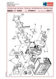
ALIMENTAZIONE COMBUSTIBILE DESTRABRENNSTOFFVERSORGUNG RECHTSRIGHT FUEL SUPPLYALIMENTATION DU COMBUSTIBLE A DROITED3592DESCRIZIONE BRUCIATORE (A)1 Anelli <strong>di</strong> sollevamento2 Girante3 Motore ventilatore4 Camma <strong>di</strong> regolazione aria5 Servomotore comando aria - <strong>gas</strong>6 Asta comando farfalla <strong>gas</strong>7 Testa <strong>di</strong> combustione8 Elettro<strong>di</strong> <strong>di</strong> accensione9 Disco <strong>di</strong> stabilità fiamma10 Quadro <strong>di</strong> controllo (vedere pag. 14)11 Cofano quadro elettrico12 Supporti bruciatore13 Ingresso aria ventilatore14 Manicotto15 Schermo per fissaggio alla caldaia16 Regolatore <strong>gas</strong>17 Otturatore18 Leva per movimento testa <strong>di</strong> combustione19 Leva per movimento testa <strong>di</strong> combustione eserranda aria20 Presa <strong>di</strong> pressione pressostato aria21 Pressostato aria22 Presa <strong>di</strong> pressione aria testa <strong>di</strong> combustione23 Pressostato <strong>gas</strong> <strong>di</strong> massima con presa <strong>di</strong>pressione24 Cellula UV (per bruciatori con funzionamentointermittente)25 Cerniera per apertura bruciatore26 Cellula UV (per bruciatori con funzionamentocontinuo)L’ apertura del bruciatore può essere effettuatasia a destra che a sinistra senza vincoli dovuti allato <strong>di</strong> alimentazione del combustibile.A bruciatore chiuso la cerniera può essere riposizionatasul lato opposto.D3593(A)12
BRENNERBESCHREIBUNG (A) - (B)1 Heberinge2 Gebläserad3 Gebläsemotor4 Luftregelnocken5 Servomotor Luft/<strong>Gas</strong> Stellantrieb6 <strong>Gas</strong>drossel-Steuerstange7 Flammkopf8 Zündelektroden9 Scheibe für Flammenstabilität10 Steuertafel (siehe Seite 14)11 Haube der Schalttafel12 Brennerhalterungen13 Lufteinlaß zum Gebläse14 <strong>Gas</strong>anschluss15 Wärmeschild für Befestigung am Heizkessel16 <strong>Gas</strong>drossel17 Schieber18 Hebel für Flammkopfbewegung19 Hebel für Flammkopf- und Schieberbewegung20 Luftdruckwächter-Druckanschluß21 Luftdruckwächter22 Luftdruckentnahmestelle23 <strong>Gas</strong>-Maximaldruckwächter mit <strong>Gas</strong>druckentnahmestelle24 UV Zelle (Brenner mit intermittierendenBetrieb)25 Scharnier für Brenneröffnung26 UV Zelle (Brenner mit Dauerbetrieb)Die Öffnung des Brenners kann sowohl rechtsals auch links erfolgen, ohne dass man an <strong>di</strong>eSeite der Brennstoffversorgung gebunden ist.Das Scharnier kann bei geschlossenem Brennerauf der entgegengesetzten Seite angeordnetwerden.BURNER DESCRIPTION (A) - (B)1 Lifting eyebolts2 Fan3 Fan motor4 Air adjustment cam5 Air-<strong>gas</strong> control servomotor6 <strong>Gas</strong> butterfly valve control rod7 Combustion head8 Ignition electrodes9 Flame stability <strong>di</strong>sk10 Control board (see page 14)11 Electric panel board - cover12 Burner supports13 Air inlet to fan14 Manifold15 Thermal insulation screen for securingburner to boiler16 <strong>Gas</strong> regulator17 Shutter18 Lever for movement of combustion head19 Lever for movement of combustion head andair gate valve20 Air pressure switch pressure test point21 Air pressure switch22 Air pressure test point23 High-limit <strong>gas</strong> pressure switch with pressuretest point24 UV cell (burner with intermittent operation)25 Hinge for opening burner26 UV cell (burner with continuos operation)The burner can be opened either on the right orleft sides, irrespective of the side from whichfuel is supplied.When the burner is closed, the hinge can be repositionedon the opposite side.DESCRIPTION BRULEUR (A) - (B)1 Anneaux de soulèvement2 Turbine3 Moteur ventilateur4 Came de réglage air5 Servomoteur commande air-gaz6 Tige de commande vanne papillon du gaz7 Tête de combustion8 Electrodes d’allumage9 Disque de stabilité de flamme10 Tableau de contrôle (voir page 14)11 Carter tableau électrique12 Supports brûleur13 Entrée air dans le ventilateur14 Manchon15 Ecran thermique pour fixation à la chau<strong>di</strong>ère16 Variateur gaz17 Obturateur18 Levier pour mouvement tête de combustion19 Levier pour mouvement tête de combustionet volet d’air20 Prise de pression pressostat air21 Pressostat air22 Prise de pression air23 Pressostat maximum gaz avec prise de pression24 Cellule UV (brûleurs avec fonctionnementintermittent)25 Charnière pour ouverture brûleur26 Cellule UV (brûleurs avec fonctionnementcontinuos)On peut ouvrir le brûleur aussi bien à droite qu’àgauche sans les obstacles dus au côté d’alimentationdu combustible.Quand le brûleur est fermé, on peut remettre lacharnière de l’autre côté.13
QUADRO ELETTRICO - SCHALTTAFELPANEL BOARD - TABLEAU ELECTRIQUEDESCRIZIONE QUADRO ELETTRICO (A)1 Portafusibili motore ventilatore2 Portafusibile per ausiliari3 Relè4 Avviatore stella/triangolo5 Selettore spento-automatico-manuale6 Segnalazione luminosa tensione ausiliari7 Selettore aumento-<strong>di</strong>minuzione potenza8 Segnalazione luminosa bruciatore in marcia9 Apparecchiatura elettrica10 Segnalazione luminosa blocco motore11 Segnalazione luminosa blocco bruciatore epulsante luminoso <strong>di</strong> sblocco12 Pulsante <strong>di</strong> emergenza13 Trasformatore d’accensione14 Piastra passacavi Pg 29 e Pg 11 per collegamentiinterni ed esterni15 Spine-prese co<strong>di</strong>ficate <strong>di</strong> collegamento16 Morsettiera alimentazione principale17 Uscita relè contatti puliti18 Relè sequenza fase19 Pre<strong>di</strong>sposizione per regolatore <strong>di</strong> potenzaRWF4020 Da<strong>di</strong> per la rimozione del pannello porta pulsantie segnalazioni21 Morsettiera per collegamenti RWF40(A)D8507NOTAIn caso <strong>di</strong> manutenzione (sostituzionemotore o girante) la piastra 14)(A) èasportabile, le spine-prese 15)(A) co<strong>di</strong>ficatepermettono la separazione senzaoperazione <strong>di</strong> scablatura.Per agevolare la manutenzione al quadro elettricoè possibile ribaltare il pannello che sostienei pulsanti 1)(B). Per effettuare questa operazioneoccorre togliere i da<strong>di</strong> 2)(B) che fissano ilpannello 3)(B) e ribaltare lo stesso come in fig.(B).Riavvitare a mano i da<strong>di</strong> dei sostegni inferioriper fissare il pannello nella nuova posizione.(B)D2965IMBALLO - VERPACKUNGPACKAGING - EMBALLAGENOTAVi sono due possibilità <strong>di</strong> blocco del bruciatore:Blocco apparecchiatura: l’accensione dellaspia sul pannello 11)(A) avverte che il bruciatoreè in blocco.Per sbloccare premere il pulsante <strong>di</strong> sblocco11)(A).Blocco motore: per sbloccare premere il pulsantedel relè termico 4)(A).mm A B C kgMB8-10-12SM BLU 2690 1350 1170 740(C)D36IMBALLO - PESO (C) - misure in<strong>di</strong>cative• L’ imballo del bruciatore appoggia su unapedana in legno particolarmente adatta ai carrellielevatori. Le <strong>di</strong>mensioni <strong>di</strong> ingombrodell'imballo sono riportate nella tabella (C).• Il peso del bruciatore completo <strong>di</strong> imballo èin<strong>di</strong>cato nella tabella (C).CORREDO1 - Guarnizione per flangia rampa <strong>gas</strong>8 - Viti per fissare la flangia <strong>gas</strong> M 16 x 501 - Schermo termico4 - Viti per fissare la flangia del bruciatore allacaldaia: M 20 x 701 - Istruzione1 - Catalogo ricambi14
BESCHREIBUNG DER SCHALTTAFEL (A)1 Sicherungshalter Gebläsemotor2 Sicherungshalter für Hilfskreise3 Relais4 Stern-Dreieck-Anlasser5 Wählschalter Aus - Automatischer Betrieb -Manueller Betrieb6 Leuchtanzeige für Spannung der Hilfskreise7 Wählschalter Leistungserhöhung-Leistungsverminderung8 Leuchtanzeige für Brenner in Betrieb9 Steuergerät10 Leuchtanzeige für Störabschaltung derMotor11 Leuchtanzeige für Störabschaltung desBrenners und Leuchtknopf für Entriegelung12 Notstopschalter13 Zündtransformator14 Platte für Kabelführungen Pg 29 und Pg 11für Innen- und Aussenanschlüsse15 Steckkontakte16 Klemmenbrett der Hauptspeisung17 Ausgang für Reinkontakte18 Phasensequenzrelais19 Vorbereitung für Leistungsregler RWF4020 Muttern zur Entfernung der Tragplatte derTasten und Anzeigen21 Klemmenbrett für Kit RWF40ANMERKUNGIm Fall von Wartung (Ersatz von Motoroder Laufrad) kann <strong>di</strong>e Platte 14)(A) herausgenommenwerden; durch <strong>di</strong>e co<strong>di</strong>ertenSteckkontakte 15)(A) ist <strong>di</strong>e Trennungohne Entfernung der Verdrahtungmöglich.Um <strong>di</strong>e Wartung zu erleichtern, kann <strong>di</strong>e Tafelmit den Druckknöpfen 1)(B) umgekippt werden.Dazu müssen <strong>di</strong>e Muttern 2)(B) entfernt werden,welche <strong>di</strong>e Tafel 3)(B) festhalten, dann <strong>di</strong>e Tafelwie in Abb. (B) gezeigt umkippen.Die Muttern der unteren Halterungen wieder vonHand einschrauben, um <strong>di</strong>e Tafel in der neuenPosition zu befestigen.MERKEDie Störabschaltungen des Brenners könnenzweierlei Art sein:Störabschaltung des Gerätes: Das Aufleuchtender Kontrollampe an der Steuertafel des Gerätes11)(A) weist auf eine Störabschaltung desBrenners hin.Zur Entriegelung den Druckknopf 11)(A) drükken.Störabschaltung des Motors: Entriegelungdurch Drücken auf den Druckknöpf des Überstromauslöser4)(A).VERPACKUNG - GEWICHT (C) - Richtwerte• Der Brenner steht auf einem besonders für<strong>di</strong>eHandhabung mit Hubwagen geeignetemHolzrahmen. Die Außenabmessungen der Verpackungsind in Tabelle (C) aufgeführt.• Das Gesamtgewicht des Brenners einschließlichVerpackung wird aus Tabelle (C)ersichtlich.AUSSTATUNG1 - Dichtung für <strong>Gas</strong>armaturenflansch8 - Schrauben für <strong>di</strong>e Befestigung des M 16 x50 Flansches1 - Wärmeschild4 - Schrauben für <strong>di</strong>e Befestigung des Brennerflanschsam Kessel: M 20 x 701 - Anleitung1 - Ersatzteile KatalogDESCRIPTION OF PANEL BOARD (A)1 Fan motor fuse holder2 Fuse holder for accessories3 Relay4 Star-powered/delta-powered starter5 Dial for off - automatic - manual6 Signal light for auxiliary voltage7 Power <strong>di</strong>al for increase - decrease of power8 Signal light for burner in operation9 Control box10 Signal light for motor failure11 Signal light for burner failure and lightedlock-out reset button12 Emergency push-button13 Ignition transformer14 Fairleads plate Pg 29 e Pg 11 for internaland external connections15 Co<strong>di</strong>fied connection plug-socket16 Main supply terminal strip17 Relay outlet - clean contacts18 Phase sequence relay19 RWF40 power regulator pre-arrangement20 Nuts for removal of pushbutton and in<strong>di</strong>catorpanel21 RWF40 kit terminal stripNOTEIf maintenance is required (replacementof motor or fan) the plate 14)(A) is removable,the co<strong>di</strong>fied plug-socket 15)(A)allows separation without an operationof removing cables.To facilitate maintenance on panel board, thepanel supporting the push buttons 1)(B) may beturned over. Remove the nuts 2)(B) fasteningthe panel 3)(B) and turn it over (see fig. B).Manually screw the nuts on the lower supportsto fasten the panel into the new position.N.B.Two types of burner failure may occur:Control box lock-out: If the control box pilotlight 11) (A) lights up, it in<strong>di</strong>cates that the burneris in lock-out.To reset, press the lockout reset button 11)(A).Motor trip: release by pressing the push buttonon thermal 4)(A).PACKAGING - WEIGHT (C) - Approximatemeasurements• The <strong>burners</strong> stands on a wooden base whichcan be lifted by fork-lifts. Outer <strong>di</strong>mensions ofpackaging are in<strong>di</strong>cated in (C).• The weight of the burner complete with packagingis in<strong>di</strong>cated in Table (C).STANDARD EQUIPMENT1 - Flange <strong>gas</strong>ket8 - Flange fixing screws M 16 x 501 - Thermal insulation screen4 - Screws to secure the burner flange to theboiler: M 20 x 701 - Instruction booklet1 - Spare parts listDESCRIPTION TABLEAU ELECTRIQUE (A)1 Porte-fusibles moteur ventilateur2 Porte-fusibles pour relais auxiliaires3 Relais4 Démarreur étoile/triangle5 Selecteur éteint-automatique-manuel6 Signal lumineux tension relais auxiliaires7 Selecteur augmentation-<strong>di</strong>minution de puissance8 Signal lumineux brûleur allumé9 Coffret de sécurité10 Signal lumineux moteur bloqué11 Signal lumineux brûleur bloqué et boutonlumineux de déblocage12 Bouton d’urgence13 Transformateur d’allumage14 Plaque passe-câbles Pg 29 et Pg 11 pourbranchements internes et externes15 Fiches-prises co<strong>di</strong>fiées de branchement16 Plaque à bornes alimentation principale17 Sortie relais contacts propres18 Relais séquence phase19 Emplacement pour régulateur de puissanceRWF4020 Ecrous pour démonter le panneau porte boutonset signalisations21 Plaque à bornes pour kit RWF40NOTEOn peut enlever la plaque 14)(A) pourl’entretien (remplacement moteur ouroue), les fiches-prises 15)(A) co<strong>di</strong>fiéespermettent de démonter sansdébrancher les câbles.Pour faciliter l’entretien du tableau électrique,faire basculer le panneau qui soutient les boutons1)(B). Pour effectuer cette opération, enleverles écrous 2)(B) qui fixent le panneau 3)(B)et faire basculer celui-ci comme in<strong>di</strong>qué sur lafig. (B).Revisser à la main les écrous des supports inférieurspour fixer le panneau dans sa nouvelleposition.NOTEIl existe deux types de blocage du brûleur:Blocage coffret: l'allumage du voyant sur lepanneau 11)(A) avertit que le brûleur s'est bloqué.Pour le débloquer, appuyer sur le bouton 11)(A).Blocage moteur: pour le débloquer appuyersur le bouton du relais thermique 4)(A).EMBALLAGE - POIDS (C) - Mesures in<strong>di</strong>catives• Le brûleur est placé sur une palette qui peutêtre soulevée par des chariots transpalettes.Les <strong>di</strong>mensions d’encombrement de l’emballagesont reportées dans le tableau (C).• Le poids du brûleur avec son emballage estin<strong>di</strong>qué dans le tab. (C).EQUIPEMENT STANDARD1 - Joint pour bride rampe gaz8 - Vis de fixation bride M 16 x 501 - Ecran thermique4 - Vis pour fixer la bride du brûleur à la chau<strong>di</strong>ère:M 20 x 701 - Instructions1 - Catalogue pièces détachées15
INGOMBRO - ABMESSUNGENMAX. DIMENSIONS - ENCOMBREMENTINGOMBRO (A) - misure in<strong>di</strong>cativeL'ingombro del bruciatore è riportato in fig. (A).Tener presente che per ispezionare la testa <strong>di</strong>combustione il bruciatore deve essere apertoruotando la parte posteriore sulla cerniera.L'ingombro del bruciatore aperto è in<strong>di</strong>cato dallequote L e R.Prima <strong>di</strong> eseguire l’operazione sopradescrittaè necessario sganciare le aste checomandano le leve 6 e 19)(A) pag. 12.Dopo l’ispezione, ed effettuata la chiusuradel bruciatore, ricollegare le asteallo stesso foro della leva.(A)mm A B C D E F G H L M RMB8-10SM BLU 1900 660 208 413 575 DN80 1007 1079 1740 312 1570MB12SM BLU 1900 664 208 456 575 DN80 1007 1079 1740 312 1570D3611CAMPI DI LAVORO (B)La POTENZA MASSIMA va scelta entro l'areatratteggiata del <strong>di</strong>agramma.La POTENZA MINIMA non deve essere inferioreal limite minimo del <strong>di</strong>agramma:MB8SM BLU = 1300 kWMB10SM BLU = 1100 kWMB12SM BLU = 1450 kWAttenzione: il CAMPO DI LAVORO è stato ricavatoalla temperatura ambiente <strong>di</strong> 20 °C, allapressione barometrica <strong>di</strong> 1000 mbar (circa 100m s.l.m.) e con la testa <strong>di</strong> combustione regolatacome in<strong>di</strong>cato a pag. 22.RAPPORTO DI MODULAZIONEIl rapporto <strong>di</strong> modulazione, ricavato in caldaie <strong>di</strong>prova secondo la norma EN 676 è <strong>di</strong>:- 6 : 1.E’ possibile utilizzare il bruciatore con un<strong>di</strong>verso rapporto <strong>di</strong> modulazione a secondadell’applicazione; per ulteriori informazioni consultareil costruttore.CALDAIEL'abbinamento bruciatore-caldaia non pone problemise la caldaia è omologata CE e le <strong>di</strong>mensionidella sua camera <strong>di</strong> combustione sono vicinea quelle in<strong>di</strong>cate dal <strong>di</strong>agramma (C) pag. 17.Se invece il bruciatore deve essere applicato aduna caldaia non omologata CE e/o con <strong>di</strong>mensionidella camera <strong>di</strong> combustione nettamentepiù piccole <strong>di</strong> quelle in<strong>di</strong>cate dal <strong>di</strong>agramma (C),consultare i costruttori.CAMPI DI LAVORO - REGELBEREICHEFIRING RATES - PLAGES DE PUISSANCECAM. COMB. / FEUERRAUMCOMB. CHAMBER / CHAMB. COMBMB8MB10MB12(B)D244616
ABMESSUNGEN (A) - RichtwerteDie Brennerabmessungen sind in der Abb. (A)angeführt. Zur Inspektion des Flammkopfesmuß der Brenner geöffnet werden, indem derhintere Teil auf dem Scharnier gedreht wird.Der Raumbedarf des offenen Brenners ist mitden Maßen L und R angegeben.Bevor der oben beschriebene Vorgangausgeführt wird, muss <strong>di</strong>e Stange ausgehängtwerden, <strong>di</strong>e den Hebel 19)(A) Seite12 steuert.Nach der Inspektion und dem Schließendes Brenners, <strong>di</strong>e Stange wieder amgleichen Loch des Hebeln einhängen.REGELBEREICHE (B)Die HÖCHSTLEISTUNG wird innerhalb derschraffierten Zone im Diagramm gewählt.Die MINDESTLEISTUNG soll nicht niedrigersein als <strong>di</strong>e Mindestgrenze des Diagramms:MB8SM BLU = 1300 kWMB10SM BLU = 1100 kWMB12SMBLU = 1450 kWAchtung: der REGELBEREICH wurde bei einerRaumtemperatur von 20 °C, einem barometrischenDruck von 1000 mbar (ungefähr 100 mü.d.M.) und einem wie auf Seite 23 eingestelltenFlammkopf gemessen.MODULATIONSVERHÄLTNISDas Modulationsverhältnis, an Prüfkesselngemäß der Norm EN 676 ist:- 6 : 1.Je nach Anwendung kann der Brenner miteinem anderen Modulationsverhältnis benutztwerden; weitere Auskünfte sind beim Herstellererhältlich.KESSELDie Brenner-Kessel Kombination gibt keine Probleme,falls der Kessel "CE" - typgeprüft ist und<strong>di</strong>e Abmessungen seiner Brennkammer sichden im Diagramm (C) angegebenen nähern.Falls der Brenner dagegen an einem Kesselangebracht werden muß, der nicht "CE"-typgeprüftist und/oder mit Abmessungen der Brennkammer,<strong>di</strong>e entschieden kleiner als jene inDiagramm (C) angegebenen sind, sollten <strong>di</strong>eHersteller zu Rate gezogen werden.MAX. DIMENSIONS (A) - ApproximatemeasurementsThe maximum <strong>di</strong>mensions of the burner aregiven in (A). Bear in mind that inspection of thecombustion head requires the burner to beopened by rotating the rear part on the hinge.The overall <strong>di</strong>mensions of the burner when openare in<strong>di</strong>cated by L and R.Before carrying out the above-mentionedoperation it is necessary to unhook theslide bar controlling the lever 19)(A) pag. 12.After inspecting and closing the burner,re-connect the rod to the same leverhole.FIRING RATES (B)MAXIMUM OUTPUT must be selected in thehatched area of the <strong>di</strong>agram.MINIMUM OUTPUT must not be lower than theminimum limit shown in the <strong>di</strong>agram:MB8SM BLU = 1300 kWMB10SM BLU = 1100 kWMB12SM BLU = 1450 kWImportant: The FIRING RATE area values havebeen obtained considering a surroun<strong>di</strong>ng temperatureof 20°C, and an atmospheric pressureof 1000 mbar (approx. 100 m above sea level)and with the combustion head adjusted asshown on page 23.MODULATION RATIOThe modulation ratio, determined using test boilersaccor<strong>di</strong>ng to standard EN 676 is:- 6 : 1.The burner can be used with a <strong>di</strong>fferent modulationratio depen<strong>di</strong>ng on the application - contactthe manufacturer for further information.BOILERSThe burner/boiler matching does not pose anyproblems if the boiler is CE type-approved an<strong>di</strong>ts combustion chamber <strong>di</strong>mensions are similarto those in<strong>di</strong>cated in <strong>di</strong>agram (C).If the burner must be combined with a boiler thathas not been CE type-approved and/or its combustionchamber <strong>di</strong>mensions are clearly smallerthan those in<strong>di</strong>cated in <strong>di</strong>agram (C), consult themanufacturer.ENCOMBREMENT (A) - Mesures in<strong>di</strong>cativesL'encombrement du brûleur est in<strong>di</strong>qué dans letab. (A). Attention: pour contrôler la tête de combustion,ouvrir le brûleur en tournant la partiearrière sur la charnière.L'encombrement du brûleur ouvert est in<strong>di</strong>quépar les cotes L et R.Avant d’effectuer l’opération ci-dessus,décrocher la tige qui commande le levier19)(A) page 12.Après avoir contrôlé et refermé le brûleur,raccrocher la tige au trou du levier.PLAGES DE PUISSANCE (B)La PUISSANCE MAXIMUM doit être choisiedans la zone hachurée du <strong>di</strong>agramme.La PUISSANCE MINIMUM ne doit pas être inférieureà la limite minimum du <strong>di</strong>agramme:MB8SM BLU = 1300 kWMB10SM BLU = 1100 kWMB12SMBLU = 1450 kWAttention: La PLAGE DE PUISSANCE a étécalculée à une température ambiante de 20 °C,à une pression barométrique de 1000 mbar(environ 100 m au-dessus du niveau de la mer)et avec la tête de combustion réglée commein<strong>di</strong>que la page 23.RAPPORT DE MODULATIONLe rapport de modulation, obtenu sur des chau<strong>di</strong>èresd’essai selon la norme EN 676, est de- 6 : 1.Est possible d’utiliser le brûleur avec un autrerapport de modulation en fonction de l’application;contacter le fabricant pour avoir de plusamples informations.CHAUDIERESL'accouplement brûleur-chau<strong>di</strong>ère ne poseaucun problème si la chau<strong>di</strong>ère est homologuéeCE et si les <strong>di</strong>mensions de sa chambre de combustionsont proches de celles in<strong>di</strong>quées dansle <strong>di</strong>agramme (C).Par contre, si le brûleur doit être accouplé àune chau<strong>di</strong>ère non homologuée CE et/ou avecdes <strong>di</strong>mensions de la chambre de combustionplus petites que celles in<strong>di</strong>quées dans le <strong>di</strong>agramme(C), consulter le constructeur.CALDAIA DI PROVA - PRÜFKESSELTEST BOILER - CHAUDIERE D’ESSAI(C)CAM. COMB. / FEUERRAUM mCOMB. CHAMBER / CHAMB. COMBD2448CALDAIA DI PROVA (C)I campi <strong>di</strong> lavoro sono stati ricavatiin speciali caldaie <strong>di</strong> prova,secondo la norma EN 676.Riportiamo in (C) <strong>di</strong>ametro e lunghezzadella camera <strong>di</strong> combustione<strong>di</strong> prova.Esempio:Bruciatore MB8SM BLUPotenza 7000 kW:<strong>di</strong>ametro 120 cm - lunghezza 6 m.PRÜFKESSEL (C)Die Regelbereiche wurden anspeziellen Prüfkesseln entsprechendNorm EN 676 ermittelt.In (C) sind Durchmesser undLänge der Prüf-Brennkammerangegeben.Beispiel:Brenner MB8SM BLULeistung 7000 kW:Durchmesser 120 cm - Länge 6 m.TEST BOILER (C)The firing rates were set in relationto special test boilers, accor<strong>di</strong>ngto EN 676 regulations.Figure (C) in<strong>di</strong>cates the <strong>di</strong>ameterand length of the test combustionchamber.Example:MB8SM BLU burnerOutput 7000 kW:<strong>di</strong>ameter 120 cm - length 6 m.CHAUDIERE D'ESSAI (C)Les plages de puissance ont étéétablies sur des chau<strong>di</strong>èresd'essai spéciales, selon la normeEN 676.Nous reportons fig. (C) le <strong>di</strong>amätreet la longueur de la chambrede combustion d'essai.Exemple:Brûleur MB8SM BLUPuissance 7000 kW:<strong>di</strong>amètre 120 cm - longueur 6 m.17
PIASTRA CALDAIA - KESSELPLATTEBOILER PLATE - PLAQUE CHAUDIEREmm A B CMB8-10SM BLU 418 608 M 20MB12SM BLU 470 608 M 20(A)FISSAGGIO BRUCIATORE ALLA CALDAIA - BEFESTIGUNGD DES BRENNER AM HEIZKESSELSECURING THE BURNER TO THE BOILER - FIXATION DU BRULEUR A LA CHAUDIERED455INSTALLAZIONEPIASTRA CALDAIA (A)Forare la piastra <strong>di</strong> chiusura della camera <strong>di</strong>combustione come in (A). La posizione dei forifilettati può essere tracciata utilizzando loschermo termico a corredo del bruciatore.LUNGHEZZA BOCCAGLIO (B)La lunghezza del boccaglio va scelta secondo lein<strong>di</strong>cazioni del costruttore della caldaia e, in ognicaso, deve essere maggiore dello spessoredella porta della caldaia, completa <strong>di</strong> refrattario.Per le caldaie con giro dei fumi anteriore 7), ocon camera ad inversione <strong>di</strong> fiamma, eseguireuna protezione in materiale refrattario 5), trarefrattario caldaia 6) e boccaglio 4).La protezione deve consentire al boccaglio <strong>di</strong>essere estratto.Per le caldaie con il frontale raffreddato adacqua non è necessario il rivestimento refrattario5)-6)(B), se non vi è espressa richiesta delcostruttore della caldaia.(B)D1638FISSAGGIO DEL BRUCIATORE ALLACALDAIA (B)• Per non danneggiare il coperchio 2)(B) siconsiglia <strong>di</strong> toglierlo durante le operazioni<strong>di</strong> installazione.• Pre<strong>di</strong>sporre un adeguato sistema <strong>di</strong> sollevamentoagganciandosi agli anelli 3)(B).• Infilare la protezione termica data a corredosul boccaglio 4)(B).• Infilare tutto il bruciatore sul foro caldaia, precedentementepre<strong>di</strong>sposto, come in fig. (A), efissare con le viti date a corredo.La tenuta bruciatore-caldaia deve essereermetica.ACCESSIBILITÀ PARTE INTERNATESTA (C)• Aprire il bruciatore sulla cerniera come in fig.(C), dopo aver tolto il tirante della leva <strong>di</strong>movimento testa 18) pag. 12, l’asta comandofarfalla <strong>gas</strong> 6) pag. 12 e le 4 viti <strong>di</strong> fissaggio1)(C).• Togliere il pressostato <strong>gas</strong> 2)(C) allentando ildado 3)(C).• Togliendo la vite 4)(C) è possibile estrarre laparte interna sollevandola come in<strong>di</strong>cato in5)(C).(C)D359418
INSTALLATIONKESSELPLATTE (A)Die Abdeckplatte der Brennkammer wie in (A)gezeigt vorbohren. Die Position der Gewindebohrungenkann mit dem zur Grundausstattunggehörenden Wärmeschild ermittelt werden.FLAMMROHRLÄNGE (B)Die Länge des Flammrohrs wird entsprechendder Angaben des Kesselherstellers gewählt undmuß in jedem Fall größer als <strong>di</strong>e Stärke derKesseltür einschließlich feuerfestes Materialsein.Für Heizkessel mit vorderem Ab<strong>gas</strong>umlauf 7)oder mit Flammenumkehrkammer muß eineSchutzschicht aus feuerfestem Material 5), zwischenfeuerfestem Material des Kessels 6) undFlammrohr 4) ausgeführt werden.Diese Schutzschicht muß so angelegt sein, daßdas Flammrohr ausbaubar ist.Für <strong>di</strong>e Kessel mit wassergekühlter Frontseiteist <strong>di</strong>e Verkleidung mit feuerfestem Material 5)-6)(B) nicht notwen<strong>di</strong>g, sofern nicht ausdrücklichvom Kesselhersteller erfordert.BEFESTIGUNG DES BRENNERS AMHEIZKESSEL (B)• Es wird empfohlen, den Deckel 2)(B) währendder Installation zu entfernen, damit ernicht beschä<strong>di</strong>gt wird.• Ein passendes Hebesystem vorbereiten undan den Ringen 3)(B) einhängen.• Den mitgelieferten Wärmeschutz am Flammrohr4)(B) einstecken.• Wie in Abb. (A) gezeigt, den ganzen Brennerin das vorher vorbereitete Loch am Heizkesseleinstecken und mit den mitgeliefertenSchrauben befestigen.Die Dichtheit zwischen Brenner und Heizkesselmuss hermetisch sein.ZUGÄNGLICHKEIT ZUM INNENTEILDES FLAMMKOPFS (C)• Den Brenner gemäß Abb. (C) am Scharnieröffnen, nachdem <strong>di</strong>e Zugstange des Hebelsfür Kopfbewegung 18) Seite 12, <strong>di</strong>e <strong>Gas</strong>drossel-Steuerstange6) Seite 12 und <strong>di</strong>e 4Klemmschrauben 1)(C) entfernt worden sind.• Den <strong>Gas</strong>druckwächter 2)(C) entfernen, indem<strong>di</strong>e Mutter 3)(C) gelockert wird.• Indem <strong>di</strong>e Schraube 4)(C) entfernt wird, kannder Innenteil durch Heben herausgenommenwerden, siehe dazu 5)(C).INSTALLATIONBOILER PLATE (A)Drill the combustion chamber locking plate asshown in (A). The position of the threaded holescan be marked using the thermal screen suppliedwith the burner.BLAST TUBE LENGTH (B)The length of the blast tube must be selectedaccor<strong>di</strong>ng to the in<strong>di</strong>cations provided by themanufacturer of the boiler, and in any case itmust be greater than the thickness of the boilerdoor complete with its fettling.For boilers with front flue passes 7) or flameinversion chambers, protective fettling in refractorymaterial 5) must be inserted between theboiler fettling 6) and the blast tube 4).This protective fettling must not compromise theextraction of the blast tube.For boilers having a water-cooled front therefractory fettling 5)-6)(B) is not required unlessit is expressly requested by the boiler manufacturer.SECURING THE BURNER TO THEBOILER (B)• To avoid damaging the cover 2) (B) werecommend removing it before installationoperations.• Prepare an adequate system of hoisting byhooking onto the rings 3) (B).• Slip the thermal protection (standard equipment)onto the blast tube 4) (B).• Place entire burner on the boiler hole(arranged previously, see fig. (A), and fastenwith the screws given as standard equipment.The coupling of the burner-boiler must be airtight.ACCESSIBILITY TO THE INTERIOR OFTHE COMBUSTION HEAD (C)• Open burner at hinge (see fig. (C) afterremoving the stay rod of the lever for movementof combustion head 18) page 12, the<strong>gas</strong> butterfly valve control rod 6) page 12 andthe 4 fastening screws 1)(C).• Remove <strong>gas</strong> pressure-switch 2)(C) by looseningnut 3)(C).• By removing screw 4)(C) it is possible toextract the internal part by lifting it, as in<strong>di</strong>cate<strong>di</strong>n 5)(C).INSTALLATIONPLAQUE CHAUDIERE (A)Percer la plaque de fermeture de la chambre decombustion comme sur la fig.(A). La positiondes trous filetés peut être tracée en utilisantl'écran thermique fourni avec le brûleur.LONGUEUR BUSE (B)La longueur de la buse doit être choisie selonles in<strong>di</strong>cations du constructeur de la chau<strong>di</strong>ère,en tous cas, elle doit être supérieure à l'épaisseurde la porte de la chau<strong>di</strong>äre, matériauréfractaire compris.Pour les chau<strong>di</strong>ères avec circulation desfumées sur l'avant 7), ou avec chambre à inversionde flamme, réaliser une protection en matériauréfractaire 5), entre réfractaire chau<strong>di</strong>ère 6)et buse 4).La protection doit permettre l'extraction de labuse.Pour les chau<strong>di</strong>ères dont la partie frontale estrefroi<strong>di</strong>e par eau, le revêtement réfractaire 5)-6)(B) n'est pas nécessaire, sauf in<strong>di</strong>cation précisedu constructeur de la chau<strong>di</strong>ère.FIXATION DU BRULEUR A LA CHAU-DIERE (B)• Durant l’installation, il est conseillé d’enleverle couvercle 2)(B) pour ne pas l’abîmer.• Prévoir un système de soulèvement appropriéet l’accrocher aux anneaux 3)(B).• Enfiler la protection thermique de série sur labuse 4)(B).• Enfiler entièrement le brûleur sur le trou de lachau<strong>di</strong>ère prévu précédemment, comme in<strong>di</strong>quésur la fig. (A) et fixer avec les vis fourniesde série.Le groupe brûleur-chau<strong>di</strong>ère doit avoir uneétanchéité parfaite.POSSIBILITÉ D’ACCÉDER À LA PARTIEINTERNE DE LA TÊTE DE COMBUS-TION (C)• Ouvrir le brûleur sur la charnière comme in<strong>di</strong>quésur la fig. (C), après avoir enlevé le tirantdu levier de mouvement de la tête 18) page12, la tige qui commande la vanne papillon dugaz 6) page 12 et les 4 vis de fixation 1)(C).• Enlever le pressostat gaz 2)(C) en desserrantl’écrou 3)(C).• En enlevant la vis 4)(C), on peut extraire lapartie interne en la soulevant comme in<strong>di</strong>quéen 5)(C).19
(A)D3597TRASFORMAZIONE PER ALIMENTA-ZIONE GAS DA SINISTRA• Aprire il bruciatore sulla cerniera ed estrarrela parte interna come in<strong>di</strong>cato in (C) p.18.• Togliere il supporto isolatori 1) e ruotare <strong>di</strong>180° il gomito 2) agendo sulle viti 3).• Rimontare il supporto isolatori.• Sul manicotto <strong>gas</strong> togliere il pressostato 4) ela piastra 5), tramite le viti 6), per fissarla alposto del regolatore <strong>gas</strong> 7).• Analogamente togliere le viti 6) e il regolatore7) con guarnizione, per fissarlo al posto dellapiastra 5).• Sul regolatore sostituire la leva 8) con quellafornita a corredo.• A questo punto manicotto <strong>gas</strong> e parte internasono pre<strong>di</strong>sposti per alimentazione da sinistra,come da configurazioni <strong>di</strong> fig. (B) e (C).• Procedere quin<strong>di</strong> alla chiusura del bruciatoresulla cerniera serrando le 4 viti (a questopunto si può scegliere <strong>di</strong> spostare la cernierasul lato opposto).• Infine spostare il tirante della farfalla <strong>gas</strong> 6)(A)p. 12 dalla parte sinistra applicandolo fra laleva 1)(D) ed il quadrante farfalla 2)(D). (Prestareattenzione nel fissare il tirante sul forocorretto 90°, 75°, 60° e 45°).(B)D3598(C)D3637(D)D359920
UMBAU FÜR DIE GASVERSORGUNGVON LINKS• Den Brenner auf dem Scharnier öffnen unddas Innenteil herausnehmen, wie in (C) S.18gezeigt.• Die Isolatorenhalterung 1) entfernen, danndas Knie 2) durch Betätigung der Schrauben3) um 180° drehen.• Die Isolatorenhalterung wieder montieren.• An der <strong>Gas</strong>muffe, den Druckwächter 4) und<strong>di</strong>e Platte 5) mit den Schrauben 6) entfernen,um sie anstelle des <strong>Gas</strong>reglers 7) zu befestigen.• Gleichfalls <strong>di</strong>e Schrauben 6) und den Regler7) mit Dichtung entfernen, um ihn anstelle derPlatte 5) zu befestigen).• Am Regler, den Hebel 8) mit dem mitgeliefertenersetzen.• Nun sind <strong>Gas</strong>muffe und Innenteil für <strong>di</strong>e Versorgungvon links vorbereitet, gemäß Konfigurationin Abb. (B) und (C).• Dann den Brenner auf dem Scharnier schließen,indem <strong>di</strong>e 4 Schrauben festgezogenwerden (man kann nun wählen, ob dasScharnier auf <strong>di</strong>e andere Seite verschobenwerden soll).• Abschließend <strong>di</strong>e Zugstange der <strong>Gas</strong>drossel6)(A) S. 12 von der linken Seite verschiebenund zwischen Hebel 1)(D) und Drosselquadrant2)(D) anbringen (Achtung: <strong>di</strong>e Zugstangeim korrekten Loch 90°, 75°, 60° und45° befestigen).TRANSFORMATION FOR GAS SUPPLYFROM LEFT• Open burner at the hinge and remove theinsides as illustrated in (C) p.18.• Remove the insulators mount 1) and thenrotate the elbow 2) 180°, turning screws 3) asrequired.• Refit the insulators mount.• Remove the pressure switch 4) from the <strong>gas</strong>manifold and remove the plate 5), by looseningscrews 6), so that it can be fastened inplace of the <strong>gas</strong> regulator 7).• Similarly, remove the screws 6) and the regulator7), inclu<strong>di</strong>ng its seal, so that you can fastenit in place of the plate 5).• Replace the lever 8) on the regulator with theone supplied.• At this point, the <strong>gas</strong> manifold and insides areset for supply from the left, as per the configurationin fig. (B) and (C).• Next, close the burner back up at the hinge,tightening the 4 screws (at this point, you candecide to move the hinge to the other side).• Lastly, move the <strong>gas</strong> butterfly valve rod 6)(A)p. 12 to the left side, applying it between thelever 1)(D) and butterfly lever 2)(D). (Makeextra sure you fasten the rod in the right hole90°, 75°, 60° and 45°).TRANSFORMATION POUR L’ALIMEN-TATION DU GAZ À GAUCHE• Ouvrir le brûleur sur la charnière et extraire lapartie intérieure comme in<strong>di</strong>qué en (C) page18.• Enlever le support des isolateurs 1) et fairetourner le coude 2) de 180° en agissant surles vis 3).• Remonter le support des isolateurs.• Enlever le pressostat 4) et la plaque 5) sur lemanchon du gaz en desserrant les vis 6),pour fixer cette dernière à la place du régulateurdu gaz 7).• Enlever également les vis 6) et le régulateurdu gaz 7), ainsi que le joint, pour le fixer à laplace de la plaque 5).• Remplacer la levier 8) sur le régulateur parcelui fourni de série.• Le manchon du gaz et la partie intérieure sontalors prévus pour l’alimentation à gauche,comme d’après la configuration de la fig. (B)et (C).• Refermer ensuite le brûleur sur la charnièreen serrant les 4 vis (la charnière peut aussiéventuellement être montée de l’autre côté).• Déplacer pour finir le tirant de la vannepapillon du gaz 6)(A) page 12 du côté gaucheen le montant entre le levier 1)(D) et le secteurgradué 2(D). (Veiller à fixer le tirant dansle trou approprié 90°, 75°, 60° ou 45°).21
(A)POSIZIONE ELETTRODI - POSITIONIERUNG DER ELEKTRODENELECTRODES POSITION - POSITION ÉLECTRODESREGOLAZIONE TESTA DI COMBUSTIONE - FLAMMKOPFEINSTELLUNGSETTING THE COMBUSTION HEAD - REGLAGE TETE DE COMBUSTIONForo - LochHole - TrouPrima <strong>di</strong> aprire il bruciatore sulle cernierescollegare da un lato questo tiranteed il tirante della farfalla <strong>gas</strong>.Attenzione: Ricollegare correttamenteal foro utilizzato nella taratura <strong>di</strong> primoavviamento. Bevor der Brenner an den Scharnierengeöffnet wird, <strong>di</strong>ese Zugstange und <strong>di</strong>eZugstange der <strong>Gas</strong>drossel von einerSeite abtrennen.Achtung: wieder korrekt mit dem Lochverbinden, das bei der Eichung für daserste Anlassen benutzt worden ist.Before opening the burner at the hinges,detach this stay rod and the <strong>gas</strong>butterfly rod on one side.Important: re-connect it correctly to thehole used for the initial start-up setting.1568 7 10D2948MB8SM BLU MB10SM BLU MB12SM BLUPotenza - Leistung - Output - PuissancekWLevismoda a da a da aHebelsystemvon bis von bis von bisLifting assemblyfrom to from to from toLevier de transmissionde à de à de à1) 3450 5500 4000 6000 4800 75005 5500 7500 6000 8550 7500 94006 7500 8000 8550 8700 9400 96007 8000 8300 8700 9200 9600 98008 - - - - 9800 1000010 - - - - 10000 10200 Levismo 1) fisso a tacca 0 - Hebellsystem 1) fest auf Kerbe 0(B)Lifting assembly 1) set on notch 0 - Levier de transmission 1) fixes crantés 0452D2111Détacher ce tirant d’un côté avantd’ouvrir le brûleur sur les charnières etle tirant de la vanne papillon du gaz.Attention, raccrocher correctementau trou utilisé pour le réglage du premierdémarrage.POSIZIONE ELETTRODI (A)Controllare che gli elettro<strong>di</strong> siano posizionaticome in fig. (A).REGOLAZIONE TESTA DI COMBU-STIONE (B)Il servomotore 5)(A) pag.12 provvede a variarela portata d’aria in funzione della richiesta <strong>di</strong> potenzaregolando l’apertura delle serrande aria e,tramite un levismo 1), l’apertura della testa <strong>di</strong>combustione.Il numero dei fori <strong>di</strong> fulcro (5-6-7-8-10) del levismo1) corrispondono alle tacche <strong>di</strong> apertura dellatesta quando il servomotore che aziona leserrande aria compie una rotazione <strong>di</strong> 130° max,tacche lette sull’asola 2) in corrispondenzadell’in<strong>di</strong>catore 5).Allo scopo <strong>di</strong> sfruttare la massima velocitàdell’aria in uscita dalla testa, che si ottiene con lamassima apertura delle serrande aria ma con laminima apertura della testa, inizialmente fissareil tirante 4) sul foro <strong>di</strong> fulcro consigliato nella tabella(B) in base alla potenza richiesta. Nel casoche, anche con rotazione <strong>di</strong> 130° del servomotore,l’aria non sia sufficiente a garantire la massimapotenza desiderata spostare il tirante 4) sulforo successivo numericamente più alto, aumentandocosì l’apertura della testa e quin<strong>di</strong> la portatad’aria.Lo spostamento del tirante 4) sui vari fori <strong>di</strong> fulcrofa variare l’apertura massima della testa (alla rotazione<strong>di</strong> 130° del servomotore), mentre mantieneinalterata l’apertura minima (alla posizione 0°del servomotore).Per effettuare la regolazione “Levismo 1) fisso atacca 0”, secondo la nota ** della tabella (B),sganciare il tirante 4) dal levismo 1), svitare ilperno in<strong>di</strong>catore 5), al suo posto avvitare il pernoa corredo e su <strong>di</strong> esso, tramite l’apposita vite,bloccare il levismo 1) in corrispondenza dellatacca 0.Importante: Il tirante 4) va lasciato sganciato.ROTAZIONE MOTORE VENTILATORE (C)Il corretto senso <strong>di</strong> rotazione del motore è in<strong>di</strong>catodal relè sequenza fase 18 - 22 pag. 14.Dopo aver portato l’alimentazione elettrica albruciatore, occorre verificare l’accensione delled verde sul relè sequenza fase.In caso <strong>di</strong> sequenza fase non rispettata, il relènon permette l’avviamento del bruciatore.(C)D161622
POSITION DER ELEKTRODEN (A)Kontrollieren Sie, ob <strong>di</strong>e Elektroden wie in Abb.(A) ausgerichtet sind.EINSTELLUNG DES FLAMMKOPF (B)Der Stellantrieb 5)(A) Seite 12 sorgt für <strong>di</strong>e Änderungdes Luftvolumens je nach geforderterLeistung, indem er <strong>di</strong>e Öffnung der Luftklappenund durch ein Hebelsystem 1) <strong>di</strong>e Öffnung desFlammkopfs regelt.Die Anzahl der Drehpunktlöcher (5-6-7-8-10) desHebelsystems 1) entspricht der Anzahl der Öffnungskerbendes Kopfes, wenn der Stellantrieb,der <strong>di</strong>e Luftklappen betätigt, eine Drehung vonmax. 130° ausführt; <strong>di</strong>e Kerben sind am Schlitzloch2), Anzeiger 5) ersichtlich.Um <strong>di</strong>e maximale Geschwin<strong>di</strong>gkeit der am Kopfausgehenden Luft zu nutzen, <strong>di</strong>e man mit maximalerLuftklappenöffnung, aber mit minimalerKopföffnung erhält, <strong>di</strong>e Zugstange 4) anfänglichim Drehpunktloch befestigen, das nach Tabelle(B) auf der Grundlage der geforderten Wärmeleistungempfohlen ist. Sollte <strong>di</strong>e Luft auch bei 130°Drehung des Stellantriebs nicht ausreichen, um<strong>di</strong>e gewünschte Höchstleistung zu gewährleisten,<strong>di</strong>e Zugstange 4) in das Loch mit dernächst-höheren Zahl verschieben, wodurch <strong>di</strong>eKopföffnung und somit das Luftvolumen erhöhtwird.Die Verschiebung der Zugstange 4) in den verschiedenenDrehpunktlöchern bewirkt <strong>di</strong>e maximaleÖffnung des Kopfes (bei der 130° Drehungdes Stellantriebs), wogegen <strong>di</strong>e minimale Öffnung(Position 0° des Stellantriebs) unverändertbleibt.Um gemäß der Anmerkung ** in Tabelle (B) Hebelsystem1) fest auf Kerbe 0“ auszuführen, <strong>di</strong>eZugstange 4) aus dem Hebelsystem 5) aushängen,den Anzeigezapfen 5) abschrauben, andessen Stelle den mitgelieferten Zapfen anschraubenund das Hebelsystem 1) auf Kerbe 0mit der dazu vorgesehenen Schraube auf <strong>di</strong>esemblokkieren.Wichtig: <strong>di</strong>e Zugstange 4) muss ausgehängtbleiben.DREHUNG DES GEBLÄSEMOTORS (C)Der korrekte Drehsinn des Motors wird vomPhasensequenzrelais 18 - 22 S. 14 gegeben.Nachdem der Brenner mit Strom versorgt ist,muss geprüft werden, ob <strong>di</strong>e grüne LED amPhasensequenzrelais aufleuchtet.Wird <strong>di</strong>e Phasensequenz nicht eingehalten, soermöglicht das Relais das Anfahren des Brennersnicht.POSITION OF ELECTRODES (A)Make sure that the electrodes are positioned asshown in figure (A).COMBUSTION AIR SETTING (B)The servomotor 5)(A), page 12, varies air deliverybased on required output by adjusting airdamper opening and, by means of a linkage 1),combustion head opening too.The number of the fulcrum holes (5-6-7-8-10) inlinkage 1) correspond to the opening notches onthe head when the servomotor driving the airdampers turns max. 130° - notches are viewedthrough the slotted hole 2) at the in<strong>di</strong>cator 5).To get the most from the maximum speed of outletair from the head, which is obtained with theair damper on maximum opening, but the headon minimum opening, initially fix the tie rod 4) tothe fulcrum hole recommended by table (B) onthe basis of the required output. If, with a rotationof 130° by the servomotor, the air is insufficientto guarantee the maximum required output,move the tie rod 4) to the following numericallyhigher hole, thus increasing head opening andtherefore air delivery.Moving tie rod 4) onto the <strong>di</strong>fferent fulcrum holesvaries the head’s maximum opening (when theservomotor turns 130°), whilst minimum opening(when the servomotor is in the 0° position) remainsunchanged.In accordance with the note ** in table (B), tohave the lifting assembly 1) fixed on notch 0°, releasethe tie rod 4) from the lifting assembly 1),unscrew the pin in<strong>di</strong>cator 5), in its place screw inthe supplied pin and, using the specific screws,block the lifting assembly 1) in line with notch 0.Important: the tie rod 4) must remain released.ROTATION OF FAN MOTOR (C)The correct motor rotation <strong>di</strong>rection is in<strong>di</strong>catedby the phase sequence relay 18 - 22 page 14.After turning the power on to the burner, checkthe green led lights up on the phase sequencerelay.If the phase sequence is not respected, therelay does not allow the burner to start.POSITION DES ELECTRODES (A)Contrôler si les électrodes sont positionnéescomme sur la fig. (A).RÉGLAGE TÊTE DE COMBUSTION (B)Le servomoteur 5)(A) page 12 change le débitd’air selon la demande de puissance par le réglagede l’ouverture des vannes d’air à l’aide dulevier de transmission 1) et l’ouverture de la têtede combustion.Le nombre des orifices du point d’appui (5-6-7-8-10) du levier de transmission 1) correspond auxcrans d’ouverture de la tête quand le servomoteurqui actionne la vanne d’air aria tourne à 130°max. Ces crans sont lus sur la boutonnière 2)près de l’in<strong>di</strong>cateur 5).Dans le but d’exploiter la vitesse maximum del’air sortant de la tête, qui s’obtient par l’ouverturemaximum des vannes d’air, mais avec l’ouvertureminimum de la tête, fixer tout d’abord letirant 4) sur l’orifice du point d’appui conseillédans le tableau (B) sur la base de la puissancedemandée. Si, même avec une rotation de 130°du servomoteur, l’air ne suffit pas à garantir lapuissance maximum souhaitée, déplacer le tirant4) sur l’orifice suivant avec le numéro le plushaut. On augmente ainsi l’ouverture de la tête etdonc le débit d’air.Le déplacement du tirant 4) sur les <strong>di</strong>fférents orificesdu point d’appui mo<strong>di</strong>fie l’ouverture maximumde la tête (avec une rotation de 130° duservomoteur), tan<strong>di</strong>s que l’ouverture minimum(position à 0° du servomoteur) reste inchangée.Pour effectuer, selon la note ** du tableau (B), "Levier de transmission 1) fixe cranté 0 ", débloquerle tirant 4) du levier de transmission 1), dévisserle pivot in<strong>di</strong>cateur 5), remplacer par la viscreuse fournie et bloquer sur celle-ci le levier detransmission 1) près du cran 0 par la vis spéciale.Important: le tirant 4) restera décroché.ROTATION MOTEUR VENTILATEUR (C)Le sens de rotation correct du moteur est in<strong>di</strong>quépar le relais séquence de phase 18 - 22 page 14.Contrôler si le led vert sur le relais de séquencede phase s’allume après avoir branché le brûleur.En cas de non-respect de la séquence dephase, le relais ne permet pas le démarrage dubrûleur.23
D3595LINEA ALIMENTAZIONE GAS (A)• La rampa del <strong>gas</strong> va collegata all'attacco del<strong>gas</strong> 1)(A), tramite la flangia 2), la guarnizione3) e le viti 4) date a corredo del bruciatore.• La rampa può arrivare da destra o da sinistra,secondo richiesta.• Le elettrovalvole 8)-10)(B) del <strong>gas</strong> devonoessere il più vicino possibile al bruciatore inmodo da assicurare l'arrivo del <strong>gas</strong> alla testa<strong>di</strong> combustione durante il tempo <strong>di</strong> sicurezza.• Assicurarsi che il campo <strong>di</strong> taratura del regolatore<strong>di</strong> pressione (colore della molla) comprendala pressione necessaria al bruciatore.(A)(B)RAMPE GAS OMOLOGATE SECONDO EN 676NACH EN 676 TYPGEPRÜFTE GASARMATURENGAS TRAINS APPROVED ACCORDING TO EN 676RAMPES GAZ HOMOLOGUÉES SELON LA NORME EN 676(C)Ø COD.COMPONENTI - BESTANDTEILE - COMPONENTS -COMPOSANTS5) 6) 8) - 10)DN 65 3970161 GF 40065/3 FRS 5065 DMV DLE 5065/11DN 80 3970162 GF 40080/3 FRS 5080 DMV DLE 5080/11DN 100 3970163 GF 40100/3 FRS 5100 DMV DLE 5100/11DN 125 3970196 GF 40125 FRS 5125 DMV DLE 5125/11kWBruciatoreBrennerBurnerBrûleur14∆p (mbar)Rampa <strong>gas</strong><strong>Gas</strong>armaturen<strong>Gas</strong> trainRampe gaz5 - 6 - 8 - 10(mbar)D1642Farfalla <strong>gas</strong><strong>Gas</strong>drosselButterflyvalvePapillongaz13(mbar)MB8SM MB10SM MB12SM DN 65 DN 80 DN 100 DN 125G20 G25G20 G25 G20 G25 G20 G25 G20 G25 G20 G25 G20 G25 G20 G253000 7,5 11,1 49,0 73,0 22,0 32,0 10,0 15,0 4,0 6,0 1,5 2,23500 11,0 16,3 66,3 98,0 29,0 43,0 13,3 20,0 5,0 8,0 2,2 3,34000 14,0 20,7 12,5 18,5 86,0 127,3 37,5 55,0 17,5 26,0 7,0 10,0 2,9 4,34500 15,0 22,2 15,0 22,2 108,3 160,0 47,0 69,3 22,0 32,3 8,5 12,0 3,7 5,55000 18,0 26,6 18,0 26,6 17,0 25,0 58,0 85,0 27,0 40,0 10,0 15,0 4,5 6,75500 23,0 34,0 23,0 34,0 23,0 34,0 69,3 102,0 32,3 48,0 12,0 18,0 5,2 7,76000 28,0 41,4 27,0 40,0 27,0 40,0 82,0 121,0 38,3 56,5 14,5 21,5 5,7 8,46500 29,0 42,9 29,0 42,9 29,0 42,9 45,0 66,0 17,0 25,0 6,5 9,67000 40,0 59,2 40,0 59,2 40,0 59,2 51,5 76,5 20,0 29,0 7,5 11,17500 44,0 65,1 44,0 65,1 44,0 65,1 59,0 87,5 22,5 33,0 8,5 12,68000 46,0 68,1 46,0 68,1 46,0 68,1 67,0 99,0 25,5 38,0 10,0 14,88500 51,0 75,5 51,0 75,5 51,0 75,5 75,5 112,0 29,0 42,5 11,0 16,39000 62,0 91,8 54,0 80,0 84,3 125,0 32,0 47,3 12,0 17,89500 60,0 88,8 94,0 138,5 36,0 53,0 12,5 18,510000 71,0 105,0 103,5 153,0 39,0 58,0 13,0 19,2(D)RAMPA GAS (B)E' omologata secondo norma EN 676 e vienefornita separatamente dal bruciatore con ilco<strong>di</strong>ce in<strong>di</strong>cato in tabella (C).LEGENDA SCHEMA (B)1 - Condotto arrivo del <strong>gas</strong>2 - Valvola manuale3 - Giunto antivibrante4 - Manometro con rubinetto a pulsante5 - Filtro6 - Regolatore <strong>di</strong> pressione (verticale)7 - Pressostato <strong>gas</strong> <strong>di</strong> minima8 - Valvola <strong>di</strong> sicurezza VS (verticale)9 - Dispositivo controllo tenuta valvole <strong>gas</strong> 8) -9). Secondo la norma EN 676 il controllo <strong>di</strong>tenuta è obbligatorio per i bruciatori conpotenza massima superiore a 1200 kW.10- Valvola <strong>di</strong> regolazione VR (verticale)Due regolazioni:- portata d'accensione (apertura rapida)- portata massima (apertura lenta)11- Adattatore rampa-bruciatore12- Guarnizione e flangia a corredo bruciatore13- Farfalla regolazione <strong>gas</strong>14- Bruciatore15- Pressostato <strong>gas</strong> <strong>di</strong> massimaP1- Pressione alla testa <strong>di</strong> combustioneP2- Pressione a valle del regolatoreP3- Pressione a monte del filtroL - Rampa <strong>gas</strong> fornita a parte con il co<strong>di</strong>ce in<strong>di</strong>catoin tabella (C).L1- A cura dell’installatoreNotaPer la regolazione della rampa <strong>gas</strong> vedere leistruzioni che l'accompagnano.UTILIZZO DELLA TABELLA (D)- Il valore (∆p) rappresenta la <strong>di</strong>fferenza tra lapressione del <strong>gas</strong> misurata alla presa P1)(B)e la pressione in camera <strong>di</strong> combustione dellacaldaia (per<strong>di</strong>ta <strong>di</strong> carico lato fumi). In base aquesto valore <strong>di</strong> pressione <strong>di</strong>fferenziale sideduce, dalla tabella (D), la potenza in<strong>di</strong>cativamenteerogata dal bruciatore.- Per una determinata potenza la somma delvalore (∆p) + la per<strong>di</strong>ta <strong>di</strong> carico della rampa<strong>gas</strong> scelta (5 - 6 - 8 - 10)(D) + la per<strong>di</strong>ta <strong>di</strong>carico della farfalla <strong>gas</strong> (13)(D) + la pressionein camera <strong>di</strong> combustione della caldaia in<strong>di</strong>cala minima pressione del <strong>gas</strong> a monte del filtro,presa P3)(B), necessaria e sufficiente pererogare la potenza richiesta.24
GASZULEITUNG (A)• Die <strong>Gas</strong>armatur ist über Flansch 2), Dichtung3) und Schrauben 4), zur Brennerausstattunggehörend, mit dem <strong>Gas</strong>anschluß1)(A) zu verbinden.• Die Armatur kann je nach Bedarf von rechtsbzw. links zugeführt werden.• Die <strong>Gas</strong>magnetventile 8)-10)(B) sollen sonah wie möglich am Brenner liegen, damit<strong>di</strong>e <strong>Gas</strong>zufuhr zum Flammkopf sichergestelltist.• Überprüfen, ob der Einstellbereich desDruckreglers (Farbe der Feder) <strong>di</strong>e für denBrenner erforderlichen Druckwerte vorsieht.GASARMATUREN (B)Nach Norm EN 676 typgeprüft, wird gesondertmit dem in Tab. (C) angegebenen Code geliefert.ZEICHENERKLÄRUNG SCHEMA (B)1 - <strong>Gas</strong>zuleitung2 - Handbetätigtes Ventil3 - Kompensator4 - Manometer mit Druckknopfhahn5 - Filter6 - Druckregler (senkrecht)7 - <strong>Gas</strong>-Minimaldruckwächter8 - Sicherheitsmagnetventil VS (senkrecht)9 - Dichtheitskontrolleinrichtung der <strong>Gas</strong>ventile8)-9). Laut Norm EN 676 ist <strong>di</strong>e Dichtheitskontrollefür Brenner mit Höchstleistungüber 1200 kW Pflicht.10- Regelmagnetventil VR (senkrecht)Zwei Einstellungen:- Zünddurchsatz (schnellöffnend)- Höchstdurchsatz (langsamöffnend)11- Passtück Armatur-Brenner.12- Dichtung und Flansch Brennergrundausstattung13- <strong>Gas</strong>-Einstelldrossel14- Brenner15- HöchstdruckwächterP1- Druck am FlammkopfP2- Druck nach dem ReglerP3- Druck vor dem FilterL - <strong>Gas</strong>armatur gesondert mit dem in Tab. (C)angegebenen Code geliefert.L1- Vom Installateur auszuführen.MerkeZur Einstellung der <strong>Gas</strong>armaturen siehe <strong>di</strong>e beigelegtenAnleitungen.BENUTZUNG DER TABELLE (D)- Der Wert (∆p) ist <strong>di</strong>e Differenz zwischen ander <strong>Gas</strong>druckentnahmestelle P1)(B)gemessenem <strong>Gas</strong>druck und Druck in derHeizkesselbrennkammer (StrömungsverlusteAb<strong>gas</strong>seite). Auf der Grundlage <strong>di</strong>esesDifferentialdruckwertes entnimmt man derTabelle (D) <strong>di</strong>e vom Brenner abgegebene,annähernde Leistung.- Für eine bestimmte Leistung gibt <strong>di</strong>e Summedes Wertes (∆p) + Strömungsverlust dergewählten <strong>Gas</strong>armatur (5 - 6 - 8 - 10)(D) +Strömungsverlust der <strong>Gas</strong>drossel (13)(D) +Druck in der Heizkesselbrennkammer den<strong>Gas</strong>mindestdruck vor dem Filter, <strong>Gas</strong>druckentnahmestelleP3)(B), an, der zur Abgabeder verlangten Leistung nötig und ausreichen<strong>di</strong>st.GAS LINE (A)• The <strong>gas</strong> train must be connected to the <strong>gas</strong>attachment 1)(A), using flange 2), <strong>gas</strong>ket 3)and screws 4) supplied with the burner.• The <strong>gas</strong> train can enter the burner from theright or left side, depen<strong>di</strong>ng on requirements.• <strong>Gas</strong> solenoids 8)-10)(B) must be as close aspossible to the burner to ensure <strong>gas</strong> reachesthe combustion head within the safety timerange.• Make sure that the pressure governor calibrationrange (colour of the spring) comprisesthe pressure required by the burner.GAS TRAIN (B)It is type-approved accor<strong>di</strong>ng to EN 676 Standardsand is supplied separately from the burnerwith the code in<strong>di</strong>cated in Table (C).KEY TO LAYOUT (B)1 - <strong>Gas</strong> input pipe2 - Manual valve3 - Vibration damping joint4 - Pressure gauge with pushbutton cock5 - Filter6 - Pressure governor (vertical)7 - Minimum <strong>gas</strong> pressure switch8 - Safety solenoid VS (vertical)9 - <strong>Gas</strong> valve 8)-9) leak detection controldevice. In accordance with EN 676 Standards,<strong>gas</strong> valve leak detection controldevices are compulsory for <strong>burners</strong> withmaximum outputs of more than 1200 kW.10- Adjustment solenoid VR (vertical)Two adjustments:- ignition delivery (rapid opening)- maximum delivery (slow opening)11- <strong>Gas</strong> train/burner adaptor.12- Standard issue burner <strong>gas</strong>ket with flange13- <strong>Gas</strong> adjustment butterfly valve14- Burner15- Maximum <strong>gas</strong> pressure switchP1- Pressure at combustion headP2- Pressure down-line from the pressure governorP3- Pressure up-line from the filterL - <strong>Gas</strong> train supplied separately with the codein<strong>di</strong>cated in Table (C).L1- The responsability of the installer.NoteSee the accompanying instructions for theadjustment of the <strong>gas</strong> train.USING TABLE (D)- The (∆p) value represents the <strong>di</strong>fferencebetween <strong>gas</strong> pressure measured at test pointP1(B) and pressure in the boiler's combustionchamber (pressure loss flue <strong>gas</strong> side). Basedon this pressure <strong>di</strong>fference value, the table(D) gives a rough in<strong>di</strong>cation of output deliveredby the burner.- For a given output, the sum of the (∆p) value+ pressure loss of the chosen <strong>gas</strong> train (5 - 6 -8 - 10)(D) + pressure loss of the <strong>gas</strong> butterflyvalve (13)(D) + pressure in the boiler's combustionchamber gives the necessary minimum<strong>gas</strong> pressure upline from the filter, testpoint P3(B), that will be sufficient to deliverthe required output.LIGNE ALIMENTATION GAZ (A)• La rampe du gaz doit être reliée au raccorddu gaz 1)(A), par la bride 2), le joint 3) et lesvis 4) fournis de série avec le brûleur.• La rampe peut arriver par la droite ou par lagauche, au choix.• Les électrovannes 8)-10)(B) du gaz doiventêtre le plus près possible du brûleur de façonà assurer l'arrivée du gaz à la tête de combustionen un temps de sécurité.• Contrôler que la plage de réglage du régulateurde pression (couleur du ressort) recouvrela pression nécessaire au brûleur.RAMPE GAZ (B)Elle est homologuée suivant la norme EN 676 etelle est fournie séparément du brûleur avec lecode in<strong>di</strong>qué dans le tableau (C).LEGENDE SCHEMA (B)1 - Canalisation d'arrivée du gaz2 - Vanne manuelle3 - Joint anti-vibrations4 - Manomètre avec robinet à bouton poussoir5 - Filtre6 - Régulateur de pression (vertical)7 - Pressostat gaz de seuil minimum8 - Electrovanne de sécurité VS (verticale)9 - Dispositif de contrôle d'étanchéité vannes.Selon la norme EN 676, le contrôle d'étanchéitéest obligatoire pour les brûleurs ayantune puissance maximale supérieure à 1200kW.10- Electrovanne de régulation VR (verticale)Deux réglages:- débit d'allumage (ouverture rapide)- débit maxi (ouverture lente)11- Adaptateur rampe-brûleur.12- Joint et bride fournis avec le brûleur13- Papillon réglage gaz14- Brûleur15- Pressostat gaz de seuil maximumP1- Pression à la tête de combustionP2- Pression en aval du régulateurP3- Pression en amont du filtreL - La rampe gaz est fournie à part avec lecode in<strong>di</strong>qué dans le tab. (C).L1- A la charge de l'installateurNotePour le réglage de la rampe gaz voir les instructionsqui l'accompagnent.UTILISATION DU TABLEAU (D)- la valeur (∆p) représente la <strong>di</strong>fférence entre lapression du gaz mesurée à la prise P1(B) etla pression dans la chambre de combustionde la chau<strong>di</strong>ère (perte de charge côtéfumées). Déduire la puissance fournie à titrein<strong>di</strong>catif par le brûleur de le tableau (D), enfonction de cette valeur de pression <strong>di</strong>fférentielle.- Pour une puissance déterminée, la sommede la valeur (∆p) + la perte de charge de larampe gaz choisie (5 – 6 – 8 – 10)(D) + laperte de charge de la vanne papillon du gaz(13)(D) + la pression dans la chambre decombustion de la chau<strong>di</strong>ère in<strong>di</strong>que la pressionminimale du gaz en amont du filtre, priseP3)(B) nécessaire et suffisante à fournir lapuissance requise.25
REGOLAZIONI PRIMA DELL’ACCEN-SIONELa regolazione della testa <strong>di</strong> combustione è giàstata descritta a pag. 22.Altre regolazioni da fare sono:- Aprire le valvole manuali poste a monte dellarampa del <strong>gas</strong>.- Regolare il pressostato <strong>gas</strong> <strong>di</strong> minima all'inizioscala.- Regolare il pressostato aria all'inizio scala.- Sfiatare l'aria dalla tubazione del <strong>gas</strong>.E' consigliabile portare all'esterno dell'e<strong>di</strong>ficiocon un tubo in plastica l'aria sfiatata fino adavvertire l'odore del <strong>gas</strong>.- Collegare un manometro sulla presa <strong>di</strong> pressionedel <strong>gas</strong> sul pressostato <strong>gas</strong> <strong>di</strong> massima.Serve a ricavare approssimativamente lapotenza massima del bruciatore me<strong>di</strong>ante latabella (D) a pag. 32.(A)1 20 AUTO MAN - +D3638AVVIAMENTO BRUCIATOREChiudere i telecoman<strong>di</strong> e mettere l’interruttore1)(B) in posizione “MAN”.Verificare che le lampa<strong>di</strong>ne o i tester collegati alleelettrovalvole, o le spie luminose sulle elettrovalvolestesse, in<strong>di</strong>chino assenza <strong>di</strong> tensione. Sesegnalano tensione, fermare imme<strong>di</strong>atamente ilbruciatore e controllare i collegamenti elettrici.(B)D3108ACCENSIONE BRUCIATOREDopo aver fatto quanto descritto al punto precedente,il bruciatore dovrebbe accendersi. Seinvece il motore si avvia ma non compare lafiamma e l'apparecchiatura va in blocco, sbloccareed attendere un nuovo tentativo d'avviamento.Se l'accensione continua a mancare può essereche il <strong>gas</strong> non arrivi alla testa <strong>di</strong> combustioneentro il tempo <strong>di</strong> sicurezza <strong>di</strong> 3 s.Aumentare allora la portata del <strong>gas</strong> all'accensione.L'arrivo del <strong>gas</strong> al manicotto è evidenziato dalmanometro ad U (A).Ad accensione avvenuta, passare alla completaregolazione del bruciatore.REGOLAZIONE BRUCIATOREPer ottenere una regolazione ottimale del bruciatoreè necessario effettuare l'analisi dei <strong>gas</strong><strong>di</strong> scarico della combustione all'uscita della caldaia.Regolare in successione:1 - Servomotore2 - Potenza all'accensione3 - Eventuali tarature preliminari4 - Potenza MAX5 - Potenza MIN6 - Potenze interme<strong>di</strong>e tra le due7 - Pressostato aria8 - Pressostato <strong>gas</strong> <strong>di</strong> massima9 - Pressostato <strong>gas</strong> <strong>di</strong> minima26
EINSTELLUNGEN VOR DER ZÜNDUNG(mit <strong>Gas</strong>)Die Einstellung des Flammkopfs ist bereits aufSeite 23 beschrieben worden.Weitere Einstellungen sind:- handbetätigte Ventile vor der <strong>Gas</strong>armatur öffnen.- Den <strong>Gas</strong>-Mindestdruckwächter auf den Skalenanfangswerteinstellen.- Den Luft-Druckwächter auf den Skalenanfangswerteinstellen.- Die Luft aus der <strong>Gas</strong>leitung entlüften.Es wird empfohlen, <strong>di</strong>e abgelassene Luft übereinen Kunststoffschlauch ins Freie abzuführen,bis der <strong>Gas</strong>geruch wahrnehmbar ist.- Ein Manometer mit der <strong>Gas</strong>druckentnahmestelleam <strong>Gas</strong>-Maximaldruckwächter verbinden.Hiermit wird <strong>di</strong>e ungefähre Brennerhöchstleistunganhand der Tabellen auf Seite 32 ermittelt.ANFAHREN DES BRENNERSDie Fernsteuerungen einschalten und denSchalter 1)(B) in Stellung “MAN” setzen.Kontrollieren, daß an den an <strong>di</strong>e Magnetventileangeschlossenen Kontrollampen und Spannungsmessern,oder an den Kontrollampen aufden Elektroventilen, keine Spannung anliegt.Wenn Spannung vorhanden ist, sofort denBrenner ausschalten und <strong>di</strong>e Elektroanschlüsseüberprüfen.ZÜNDUNG DES BRENNERSWenn alle vorab angeführten Anleitungenbeachtet worden sind, müßte der Brenner zünden.Wenn hingegen der Motor läuft, aber <strong>di</strong>eFlamme nicht erscheint und eine Geräte-Störabschaltungerfolgt, entriegeln und das Anfahrenwiederholen.Sollte <strong>di</strong>e Zündung immer noch nicht stattfinden,könnte <strong>di</strong>es davon abhängen, daß das <strong>Gas</strong>nicht innerhalb der vorbestimmten Zeit (Sicherheitszeit3 s) den Flammkopf erreicht.In <strong>di</strong>esem Fall den <strong>Gas</strong>anfahrdurchsatz erhöhen.Das U-Rohr-Manometer (A) zeigt den <strong>Gas</strong>eintrittan der Muffe an.Nach erfolgter Zündung den Brenner vollstän<strong>di</strong>geinstellen.BRENNEREINSTELLUNGFür <strong>di</strong>e optimale Einstellung des Brenners sollten<strong>di</strong>e Ab<strong>gas</strong>e am Kesselausgang analysiertwerden.Nacheinander einstellen:1 - Stellmotors2 - Zündleistung3 - Vor-Einstellungen4 - Höchstleistung5 - Mindestleistung6 - Zwischenleistungen7 - Luft-Druckwächter8 - <strong>Gas</strong>-Höchstdruckwächter9 - <strong>Gas</strong>-MinimaldruckwächterADJUSTMENTS BEFORE FIRST FIR-ING (<strong>gas</strong> operation)Adjustment of the combustion head has beenillustrated on page 23.In ad<strong>di</strong>tion, the following adjustments must alsobe made:- Open manual valves up-line from the <strong>gas</strong> train.- Adjust the minimum <strong>gas</strong> pressure switch to thestart of the scale.- Adjust the air pressure switch to the zero positionof the scale.- Purge the air from the <strong>gas</strong> line.Continue to purge the air (we recommendusing a plastic tube routed outside the buil<strong>di</strong>ng)until <strong>gas</strong> is smelt.- Connect a manometer to the <strong>gas</strong> pressure testpoint on the high-limit <strong>gas</strong> pressure switch.The manometer rea<strong>di</strong>ngs are used to calculatethe maximum output using the table on page32.BURNER STARTINGClose the control devices and set switch 1)(B) to“MAN”.Make sure that the lamps or testers connectedto the solenoids, or pilot lights on the solenoidsthemselves, in<strong>di</strong>cate that no voltage is present.If voltage is present, then imme<strong>di</strong>ately stop theburner and check electrical connections.BURNER FIRINGHaving completed the checks in<strong>di</strong>cated in theprevious hea<strong>di</strong>ng, the burner should fire. If themotor starts but the flame does not appear andthe control box goes into lock-out, reset and waitfor a new firing attempt.If firing is still not achieved, it may be that <strong>gas</strong> isnot reaching the combustion head within thesafety time period of 3 seconds.In this case increase <strong>gas</strong> firing delivery.The arrival of <strong>gas</strong> at the sleeve is in<strong>di</strong>cated bythe U-type manometer (A).Once the burner has fired, now proceed withglobal calibration operations.BURNER CALIBRATIONThe optimum calibration of the burner requiresan analysis of the flue <strong>gas</strong>es at the boiler outlet.Adjust successively:1 - Servomotor2 - First firing output3 - Preliminary calibrations (if required)4 - Max. burner output5 - Min. burner output6 - Interm. outputs between Min. and Max.7 - Air pressure switch8 - Maximum <strong>gas</strong> pressure switch9 - Minimum <strong>gas</strong> pressure switchREGLAGES AVANT L'ALLUMAGE (avecgaz)Le réglage de la tête de combustion a déjà étédécrit page 23.Les autres réglages à effectuer sont les suivants:- Ouvrir les vannes manuelles situées en amontde la rampe du gaz.- Régler le pressostat gaz seuil minimum endébut d'échelle.- Régler le pressostat air en début d'échelle.- Purger le conduit du gaz.Il est conseillé d'évacuer l'air purgé en dehorsdes locaux par un tuyau en plastique jusqu'àce que l'on sente l'odeur caractéristique dugaz.- Relier un manomètre sur la prise de pressiondu gaz sur le pressostat gaz seuil maximum.Il sert à mesurer approximativement la puissancemaximum du brûleur à l'aide de tableaude la page 32.DEMARRAGE BRULEURFermer les télécommandes et placer l’interrupteur1)(B) en position “MAN”.Vérifier que les ampoules ou les testeurs raccordésaux électrovannes, ou les voyants sur lesélectrovannes, in<strong>di</strong>quent une absence de tension.S'ils signalent une tension, arrêter immé<strong>di</strong>atementle brûleur et contrôler lesraccordements électriques.ALLUMAGE BRULEURAprès avoir effectué les opérations décrites aupoint précédent, le brûleur devrait s'allumer. Sile moteur démarre mais la flamme n'apparaîtpas et le boîtier de contrôle se bloque, réarmeret faire une nouvelle tentative de démarrage.Si l'allumage ne se fait pas, il se peut que le gazn'arrive pas à la tête de combustion dans letemps de sécurité de 3 s.Dans ce cas augmenter le débit du gaz à l'allumage.L'arrivée du gaz au manchon est mise enévidence par le manomètre en U (A).Quand l'allumage est fait, passer au réglagecomplet du brûleur.REGLAGE BRULEURPour obtenir un réglage optimal du brûleur, ilfaut effectuer l'analyse des gaz d'échappementde la combustion à la sortie de la chau<strong>di</strong>ère.Régler en succession:1 - Servomoteur2 - Puissance à l'allumage3 - Eventuels réglages préliminaires4 - Puissance maximum brûleur5 - Puissance minimum brûleur6 - Puissances intermé<strong>di</strong>aires entre les deux7 - Pressostat air8 - Pressostat seuil maximum du gaz9 - Pressostat seuil minimum du gaz27
SERVOMOTORE - STELLANBETRIEB - SERVOMOTOR - SERVOMOTEURCONECTRON(A)SERVOMOTORE - STELLANBETRIEB - SERVOMOTOR - SERVOMOTEURLANDISD682D711 - SERVOMOTORE (A) - (B)Il servomotore 5)(A) pag.12 può essere della<strong>di</strong>tta Conectron (A) o della <strong>di</strong>tta Lan<strong>di</strong>s (B).Il servomotore regola contemporaneamente laserranda dell'aria tramite la camma a profilovariabile e la farfalla del <strong>gas</strong>.Compie una rotazione <strong>di</strong> 130° in 45 s.E' dotato <strong>di</strong> tre camme regolabili (LANDIS 7camme <strong>di</strong> cui 4 non utilizzate), che azionanoaltrettanti contatti, così posizionate in fabbrica:1)(A) Camma blu Conectron : 0°2)(B) Camma Lan<strong>di</strong>s : 0°Limita la rotazione verso il minimo.A bruciatore spento la serranda dell’ariadeve risultare chiusa.2)(A) Camma rossa Conectron : 130°1)(B) Camma Lan<strong>di</strong>s : 130°Limita la rotazione verso il massimo.3)(A) Camma nera Conectron : 20°3)(B) Camma Lan<strong>di</strong>s : 20°Regola la posizione <strong>di</strong> accensione epotenza MIN.4(A) Vite <strong>di</strong> regolazione (solo Conectron)5(A-B) In<strong>di</strong>ce posizione camme6(A-B) Leva per svincolare il servomotoreLe camme 1) e 2) non devono essere spostate.La camma 3) può subire una rotazione tra 10 e30°, come spiegato più avanti.Ogni camma è dotata <strong>di</strong> una vite 4) che regola ilpunto <strong>di</strong> intervento dei contatti (solo Conectron).NOTAIl servomotore raffigurato nelle altre pagine delmanuale è della <strong>di</strong>tta Conectron, fig. (A).Se il bruciatore è dotato del servomotore della<strong>di</strong>tta Lan<strong>di</strong>s, fig. (B), tenere conto della funzionedelle camme come sopra specificato.(B)D6832 - POTENZA ALL’ACCENSIONESecondo norma EN 676:<strong>Bruciatori</strong> con potenza MAX oltre i 120 kWL'accensione deve avvenire ad una potenzaridotta rispetto alla potenza max <strong>di</strong> funzionamento.La norma stabilisce che il suo valore sia definitoin funzione del tempo <strong>di</strong> sicurezza "ts" dell'apparecchiaturaelettrica.La potenza me<strong>di</strong>a erogata nel tempo <strong>di</strong> sicurezzadeve essere uguale od inferiore:ad 1/2 della potenza massima richiesta per ts = 2 secad 1/3 della potenza massima richiesta per ts = 3 secEsempio:potenza MAX <strong>di</strong> funzionamento 6000 kW.La potenza erogata nel tempo <strong>di</strong> sicurezza deveessere uguale o inferiore a:• 3000 kW con ts = 2 s;• 2000 kW con ts = 3 s.La valvola <strong>gas</strong> 10)(B) pag. 32 è munita <strong>di</strong> frenoè possibile variare la potenza erogata nel tempo<strong>di</strong> sicurezza.La prima accensione del bruciatore va eseguitalasciando inalterate le regolazioni del <strong>gas</strong> edell’aria pre<strong>di</strong>sposte in fabbrica.Nel caso <strong>di</strong> mancata accensione ripetere la fase<strong>di</strong> accensione una seconda volta.Se perdura la <strong>di</strong>fficoltà <strong>di</strong> accensione, per facilitarel’accensione stessa ridurre eventualmentela portata <strong>di</strong> aria, tramite le opportune viti 1)(A)pag. 30 <strong>di</strong> regolazione del gruppo camma, e/oaumentare la portata <strong>di</strong> <strong>gas</strong> incrementando lapressione in uscita dal regolatore 6)(B) pag. 32.28
1 - STELLANTRIEB (A) - (B)Der Stellantrieb 5)(A) S.12 kann von der FirmaConectron (A) oder der Firma Lan<strong>di</strong>s (B) geliefertwerden.Der Stellantrieb regelt <strong>di</strong>e Luftklappe über daseinstellbare Nockenprofil gleichzeitig mit der<strong>Gas</strong>drossel.Er führt eine Drehung von 130° in 45 s aus.Er ist mit drei einstellbaren Nocken ausgerüstet(LANDIS 7 Nocken von denen 4 ungebraucht),<strong>di</strong>e ebenso viele Schalter betätigen:1)(A) Blauer Nocken Conectron : 0°2)(B) Nocken Lan<strong>di</strong>s : 0°Begrenzt <strong>di</strong>e Drehung in Richtung Mindestwert.Bei Brennerstillstand muß <strong>di</strong>eLuftklappe geschlossen sein.2)(A) Roter Nocken Conectron : 130°1)(B) Nocken Lan<strong>di</strong>s : 130°Begrenzt <strong>di</strong>e Drehung in RichtungHöchstwert.3)(A) Schwarzer Nocken Conectron : 20°3)(B) Nocken Lan<strong>di</strong>s : 20°Bezeichnet <strong>di</strong>e Position "Brenner ein"sowie <strong>di</strong>e Mindestleistung.4(A) Einstellschraube (nur Conectron)5(A-B) Nockenstellungsanzeiger6(A-B) Hebel zum Aushängen des StellmotorsDie Nocken 1) und 2) dürfen nicht verstellt werden.Der Nocken 3) kann um 10 - 30° verstellt werden,wie nachstehend erklärt wird.Jeder Nocken ist mit einer Schraube 4) versehen,<strong>di</strong>e <strong>di</strong>e genaue Eingriffsstelle der Schalterregelt (nur Conectron).BEMERKUNGDer in den anderen Seiten des Handbuchs dargestellteStellmotor wird von der Firma Conectron,Abb. (A), geliefert.Wenn der Brenner mit dem Servomotor derFirma Lan<strong>di</strong>s, Abb. (B) versehen ist, berücksichtigenSie <strong>di</strong>e Nockenfunktion wie obenangeführt.2 - ZÜNDLEISTUNGNach Norm EN 676:Brenner mit Höchstleistung über 120 kWDie Zündung hat bei einer verringerten Leistungim Vergleich zur höchsten Betriebsleistung zuerfolgen.Die Norm legt fest, daß ihr Wert in Abhängigkeitvon der Sicherheitszeit "ts" des Steuergerätesdefiniert wird.Die in der Sicherheitszeit abgegebene Durchschnittsleistungmuss gleich oder kleiner sein als:1/2 der für ts = 2 Sek. verlangten Höchstleistung1/3 der für ts = 3 Sek. verlangten HöchstleistungBeispiel:höchste Betriebsleistung 6000 kW.Die in der Sicherheitszeit abgegebene Leistungmuss gleich oder kleiner sein als:• 3000 kW bei ts = 2 s;• 2000 kW bei ts = 3 s.Das <strong>Gas</strong>ventil 10)(B) Seite 32 ist mit Bremseausgestattet; <strong>di</strong>e in der Sicherheitszeit abgegebeneLeistung kann variiert werden.Bei der ersten Brennerzündung müssen <strong>di</strong>ewerkseitig ausgeführten <strong>Gas</strong>- und Lufteinstellungenunverändert gelassen werden.Die Zündphase ein zweites Mal wiederholen,falls keine Zündung erfolgt.Sollten weiterhin Zündprobleme bestehen, kannder Luftdurchsatz ggf. mit den Stellschrauben1)(A) S. 30 der Nockengruppe verringert und/oder der <strong>Gas</strong>durchsatz erhöht werden, indemder Druck im Ausgang des Reglers 6)(B) S. 32erhöht wird.1 - SERVOMOTOR (A) - (B)Servomotor 5)(A) p.12 can be supplied byConectron (A) or by Lan<strong>di</strong>s (B).Servomotor simultaneously regulates the airgate valve via the variable profile cam and the<strong>gas</strong> butterfly valve.A rotation of 130° is made in 45 s.It is fitted with three adjustable cams operatingthree contacts (LANDIS 7 cams of which 4 arenot utilized), which are factory-set as follows :1)(A) Blue Cam Conectron : 0°2)(B) Cam Lan<strong>di</strong>s : 0°Restricts rotation to minimum.When the burner is OFF, the air gatevalve is closed.2)(A) Red Cam Conectron : 130°1)(B) Cam Lan<strong>di</strong>s : 130°Restricts rotation to maximum.3)(A) Black Cam Conectron : 20°3)(B) Cam Lan<strong>di</strong>s : 20°This is the firing and MIN output position.4(A) Adjustment screw (Conectron only)5(A-B) Cam position in<strong>di</strong>cator6(A-B) Servomotor releasing leverCams 1) and 2) must not be mo<strong>di</strong>fied.Cam 3) may be rotated between 10° and 30°, asexplained below.Each cam is fitted with a screw 4) which regulatesthe contact action point (Conectron only).NOTEThe servomotor represented on the other pagesof the booklet is supplied by Conectron, fig. (A).If the burner is fitted with the servomotor suppliedby Lan<strong>di</strong>s, fig. (B), you should bear in mindthe function of the cam as it is in<strong>di</strong>cated above.2 - FIRING OUTPUTAccor<strong>di</strong>ng to EN 676 Regulations:<strong>Burners</strong> with MAX output above 120 kWFiring must be performed at a lower output thanthe max. operation output.The regulations prescribe that the value bedefined accor<strong>di</strong>ng to the control box safety time"ts".Average output delivered within the safety timemust be equal to or lower than:1/2 of required maximum output with ts = 2 sec1/3 of required maximum output with ts = 3 secExample:MAX operation output of 6000 kW.Output delivered within the safety time must beequal to or lower than:• 3000 kW with ts = 2 s;• 2000 kW with ts = 3 s.The <strong>gas</strong> valve 10)(B) page 32 features a brakeand output delivered within the safety time canbe varied.The burner's first start-up must be performedleaving the factory <strong>gas</strong> and air settings as theyare.If the burner fails to start, repeat the start-upphase a second time.If starting <strong>di</strong>fficulty persists, you may need toreduce airflow to facilitate start-up (do this bymeans of the relevant screws 1)(A) page 30 foradjusting the cam assembly and/or increase <strong>gas</strong>flow by increasing outlet pressure from theregulator 6)(B) page 32.1 - SERVOMOTEUR (A) - (B)Le servomoteur 5)(A) p.12 peut être de la sociétéConectron (A) ou de l'entreprise Lan<strong>di</strong>s (B).Le servomoteur règle en même temps le voletd'air au moyen de la came à profil variable et lepapillon du gaz.Il effectue une rotation de 130° en 45 s.Il possède 3 cames réglables qui actionnent lemême nombre de contacts (LANDIS 7 camesdont 4 inutilisées, positionnées de la façon suivanteen usine:1)(A) Came bleue Conectron : 0°2)(B) Came Lan<strong>di</strong>s : 0°Limite la rotation vers le minimum. Lorsquele brûleur est éteint, le volet d'airdoit être fermé.2)(A) Came rouge Conectron : 130°1)(B) Came Lan<strong>di</strong>s : 130°Limite la rotation vers le maximum3)(A) Came noire Conectron : 20°3)(B) Came Lan<strong>di</strong>s : 20°C'est la position d'allumage et de puissanceMIN4(A) Vis de régulation (Conectron uniquement)5(A-B) Index position cames6(A-B) Levier pour dégager le servomoteurLes cames 1) et 2) ne doivent pas être déplacées.La came 3) peut subir une rotation entre10° et 30° comme cela est expliqué plus loin.Chaque came est dotée d'une vis 4) qui règle lepoint d'actionnement des contacts.(Conectron uniquement).NOTELe servomoteur figurant dans les autres pagesdu manuel est de la société Conectron, fig. (A).Si le brûleur est équipé du servomoteur del'entreprise Lan<strong>di</strong>s, fig. (B), tenir compte de lafonction des cames comme spécifié ci-dessus.2 - PUISSANCE A L'ALLUMAGESelon la norme EN 676:Brûleurs avec puissance MAX au delà de 120 kWL'allumage doit se faire à une puissance réduitepar rapport à la puissance maximum de fonctionnement.La norme établit que sa valeur soit définie enfonction du temps de sécurité "ts" du coffret desécurité.La puissance moyenne fournit durant le temps demise en sécurité doit être égale ou inférieure:à la moitié de la puissance maximale requisepour ts = 2 sà un tiers de la puissance maximale requisepour ts = 3 sExemple:puissance MAX de fonctionnement 6000 kW.La puissance fournie durant le temps de miseen sécurité à l'allumage doit être égale ou inférieureà:• 3000 kW avec ts = 2 s;• 2000 kW avec ts = 3 s.La vanne papillon du gaz 10)(B) page 32 estmunie d’un frein. Il est donc possible de varier lapuissance fournie durant le temps de mise ensécurité.Le premier allumage du brûleur doit êtreeffectué sans mo<strong>di</strong>fier les réglages prévus enusine pour le gaz et pour l’air.Si l’allumage ne se fait pas, répéter la phased’allumage une seconde fois.Si la <strong>di</strong>fficulté d’allumage persiste, réduire éventuellementle débit d’air à l’aide des vis correspondantes1)(A) page 30 qui règlent le groupecame et/ou augmenter le débit du gaz en augmentantla pression à la sortie du régulateur 6)(B) page 32 pour faciliter cette opération.29
(A)D36003 - TARATURE PRELIMINARIRegolazione della farfalla <strong>gas</strong>Il tirante 6)(A) pag. 12 può essere collegato aduno dei quattro fori presenti sul levismo (A) checomanda l’apertura della farfalla del regolatore<strong>gas</strong> 16)(A) pag. 12.Il valore numerico stampigliato in prossimità <strong>di</strong>ognuno dei fori rappresenta la rotazione angolareimposta alla farfalla <strong>gas</strong>, relativa all’interarotazione <strong>di</strong> 130° del gruppo camma 4)(A) pag.12.Normalmente il tirante va posizionato sul foro90° (collegamento eseguito in fabbrica).Il collegamento del tirante ad un altro foro (75° -60° - 45°) va eseguito solo in due casi specifici.1° caso: se la minima pressione in uscita dalregolatore <strong>di</strong> pressione 6)(B) pag. 32 è troppoalta e non permette <strong>di</strong> regolare la portata massima<strong>di</strong> <strong>gas</strong> erogata dal bruciatore alla portatarichiesta dalla caldaia;- o si sostituisce la molla del regolatore conuna che permette <strong>di</strong> avere una minore pressionedel <strong>gas</strong> a monte della farfalla- oppure, se non si <strong>di</strong>spone <strong>di</strong> una molla idonea,si collega il tirante ad un foro che provocauna minor apertura della farfallalimitando così la massima portata <strong>di</strong> <strong>gas</strong> alvalore richiesto.2° caso: nel caso in cui, per particolari esigenze<strong>di</strong> modulazione della potenza erogata dal bruciatore,si desideri ottimizzare la linearità <strong>di</strong>regolazione tra la portata <strong>di</strong> <strong>gas</strong> e la variazioneangolare <strong>di</strong> apertura della farfalla, è necessariolimitare la rotazione massima della farfalla a 60°o 45°.30
3 - EINSTELLUNGENRegelung der <strong>Gas</strong>drosselDie Zugstange 6)(A) S. 12 kann mit einem dervier Löcher am Hebelsystem (A), das <strong>di</strong>eDrossel des <strong>Gas</strong>reglers 16)(A) S. 12 öffnet,verbunden werden.Die in der Nähe eines jeden Lochs aufgeprägteZahl ist <strong>di</strong>e Winkeldrehung der <strong>Gas</strong>drosselbezüglich der ganzen 130° Drehung derNockengruppe 4)(A) S. 12.Gewöhnlich muss <strong>di</strong>e Zugstange in das Loch90° positioniert werden (werkseitig ausgeführteVerbindung).Die Verbindung der Zugstange mit einem anderenLoch (75° - 60° - 45°) darf nur in zwei besonderenFällen ausgeführt werden.1. Fall: wenn der Mindestdruck im Ausgang ausdem Druckregler 6)(B) S. 32 zu hoch ist und dervom Brenner abgegebene maximale <strong>Gas</strong>durchsatznicht auf den vom Heizkessel verlangtenDurchsatz geregelt werden kann;- entweder ersetzt man <strong>di</strong>e Reglerfeder miteiner anderen, <strong>di</strong>e einen niedrigeren <strong>Gas</strong>druckvor der Drossel ermöglicht- oder, wenn man über eine geeignete Federnicht verfügt, man verbindet <strong>di</strong>e Zugstangemit einem Loch, das eine geringere Öffnungder Drossel verursacht und begrenzt so denmaximalen <strong>Gas</strong>durchsatz je nach verlangtemWert.2. Fall: wenn man aufgrund besonderer Modulationserforderungender vom Brenner abgegebenenLeistung <strong>di</strong>e Regellinearität zwischen<strong>Gas</strong>durchsatz und Öffnungswinkelverschiebungder Drossel optimieren will, muss <strong>di</strong>eHöchstdrehung der Drossel auf 60° oder 45°begrenzt werden.3 - PRELIMINARY CALIBRATIONS<strong>Gas</strong> butterfly valve adjustmentThe rod 6)(A) page 12 can be connected to oneof the four holes on the lever (A) controllingopening of the butterfly valve pertaining to the<strong>gas</strong> regulator 16)(A) page. 12.The numerical value stamped near each of theholes represents the angle the <strong>gas</strong> butterflyvalve is caused to rotate, related to the whole130° rotation of the cam assembly 4)(A) page12.The rod is usually positioned in the 90° hole(connection made at the factory).The rod should only be connected to a <strong>di</strong>fferenthole (75° - 60° - 45°) in two specific cases.1 st case: if minimum outlet pressure from thepressure regulator 6)(B) page 32 is too high anddoes not allow the maximum <strong>gas</strong> flow deliveredby the burner to be adjusted to the deliveryrequired by the boiler;- either you must replace the regulator's springwith one that allows lower <strong>gas</strong> pressure uplinefrom the butterfly valve- or, if you do not have a suitable spring, youcan connect the rod to a hole causing the butterflyvalve to open less, thus limiting themaximum <strong>gas</strong> flow to the required value.2 nd case: if there is a special need to modulateoutput delivered by the burner and you want tooptimize adjustment linearity between <strong>gas</strong> flowand the <strong>di</strong>fferent angles the butterfly valveopens by, maximum butterfly valve rotationmust be limited to 60° or 45°.3 - RÉGLAGES PRÉLIMINAIRESRéglage de la vanne papillon du gazLe tirant 6)(A) page 12 peut être relié à un desquatre trous prévus sur le système de leviers(A) qui commande l’ouverture de la vannepapillon du gaz du régulateur gaz 16)(A) page12.La valeur numérique gravée à proximité dechacun des trous représente la rotationangulaire imposée à la vanne papillon du gaz etqui correspond à la rotation complète de 130°du groupe came 4) (A) page 12.Le tirant doit normalement être placé sur le trou90° (raccordement effectué en usine).Le raccordement du tirant à un autre trou (75° -60° ou- 45°) ne doit être fait que dans deux casspécifiques.1 er cas : si la pression minimale à la sortie durégulateur de pression 6) (B) page 32 est tropélevée et ne permet pas d’adapter le débit maximalde gaz fourni par le brûleur au débit requispar la chau<strong>di</strong>ère;- il faut alors remplacer le ressort du régulateurpar un ressort permettant d’avoir une pressioninférieure du gaz en amont de la vannepapillon- s’il l’on ne <strong>di</strong>spose pas d’un ressort approprié,relier le tirant à un trou qui provoque uneouverture plus réduite de la vanne papillon dugaz, en limitant ainsi le débit maximal de gazà la valeur requise.2 ème cas : si l’on désire optimiser la linéarité deréglage entre le débit de gaz et la variationangulaire d’ouverture de la vanne papillon dugaz pour des exigences particulières de modulation,il est nécessaire de limiter la rotationmaximale de cette dernière à 60 ou 45°.31
4 - POTENZA MASSIMALa potenza MAX, 2° sta<strong>di</strong>o, va scelta entro ilcampo <strong>di</strong> lavoro MAX riportato a pag. 16.Regolazione <strong>gas</strong> MAX- Dopo aver effettuato l’accensione del bruciatore,con selettore 1)(B) posto sulla posizionemanuale, tenere premuto il selettore 2)(B)sulla posizione (+) fino ad ottenere la completarotazione a 130° del servomotore (A)con conseguente apertura della serranda ariae della farfalla <strong>gas</strong>.- Quin<strong>di</strong>, tramite il regolatore <strong>di</strong> pressione 6)(B)pag. 32, variare la pressione del <strong>gas</strong> in uscitadal regolatore stesso fino ad ottenere la portata<strong>di</strong> <strong>gas</strong> richiesta.- La misura della portata <strong>di</strong> <strong>gas</strong> va eseguita utilizzandoil contatore <strong>gas</strong> <strong>di</strong> linea. In assenza<strong>di</strong> un contatore <strong>gas</strong> la potenza erogata dalbruciatore può essere in<strong>di</strong>cativamente ricavatautilizzando la tabella (D) pag. 32.Regolazione aria MAXVariare il profilo finale della camma 2)(A)agendo sulle viti 1) sul lato superiore dellacamma. Non agire su una sola vite, ma anchesu quelle vicine in modo che la curvatura dellacamma sia progressiva.- Per aumentare la portata d'aria avvitare la vite- Per <strong>di</strong>minuire la portata d'aria svitare la vite.(A)1 2D36010 AUTO MAN - +5 - POTENZA MINIMALa potenza minima, 1°sta<strong>di</strong>o, va scelta nellagamma dei valori MIN riportati sopra i <strong>di</strong>agrammi<strong>di</strong> pag. 16.Regolazione <strong>gas</strong> MIN- Tenere premuto il selettore 2)(B) sulla posizione(-), con conseguente chiusura della serrandaaria e della farfalla <strong>gas</strong>, fino adottenere la portata <strong>di</strong> <strong>gas</strong> minima desiderata.- Quin<strong>di</strong> variare la regolazione <strong>di</strong> fabbrica dellacamma 3)(A-B) pag. 26 in funzione della posizionedel servomotore (A) precedentementeottenuta. Questa regolazione definisce anchela posizione <strong>di</strong> accensione del bruciatore.Regolazione aria MINVariare il profilo iniziale della camma 2)(A)agendo gradualmente sulle viti 1).Fare attenzione <strong>di</strong> non mo<strong>di</strong>ficare la parte <strong>di</strong>profilo finale che regola la serranda alla massimaportata, precedentemente definita.(B)D31086 - POTENZE INTERMEDIERegolazioni interme<strong>di</strong>eDopo aver regolato la potenza massima eminima del bruciatore si provvede ad eseguirela regolazione dell’aria su più posizioni interme<strong>di</strong>edel servomotore (A-B) pag. 26.Il passaggio da una posizione alla successiva siottiene tenendo premuto il selettore 2)(B) sulsimbolo (+) o (-).Per una migliore ripetibilità <strong>di</strong> regolazione averel’avvertenza <strong>di</strong> fermare la rotazione del gruppocamma (A) quando il cuscinetto superiore chescorre sul profilo 2)(A) si trova allineato con unadelle viti <strong>di</strong> regolazione 1)(A).Avvitare o svitare la vite 1)(A) prescelta peraumentare o <strong>di</strong>minuire la portata <strong>di</strong> aria in mododa adeguarla alla corrispondente portata <strong>di</strong> <strong>gas</strong>.Eseguite le regolazioni delle potenze (massima,minima ed interme<strong>di</strong>e), è importante bloccaretutte le viti <strong>di</strong> regolazione dell’aria 1)(A) tramitele viti <strong>di</strong> bloccaggio 3)(A) in modo da evitarepossibili spostamenti dalle posizioni <strong>di</strong> taraturaaria - <strong>gas</strong>.32
4 - HÖCHSTLEISTUNGDie Höchstleistung, 2. Stufe, wird innerhalb desauf Seite 16 gezeigten MAX Einstellbereichsgewählt.<strong>Gas</strong>einstellung auf Höchstwert- Nach der Durchführung der Brennerzündung,mit Wählschalter 1)(B) auf „manuell“ gestellt,den Wählschalter 2)(B) in Position (+)gedrückt halten, bis <strong>di</strong>e vollstän<strong>di</strong>ge 130°Drehung des Stellantriebs (A) mit folglicherÖffnung der Luftklappe und der <strong>Gas</strong>drosselerfolgt ist.- Den <strong>Gas</strong>druck im Ausgang aus dem Reglerdann über den Druckregler 6)(B) S. 32 variieren,bis der verlangte <strong>Gas</strong>durchsatz erreichtist.- Der <strong>Gas</strong>durchsatz wird mit dem <strong>Gas</strong>zählerder <strong>Gas</strong>leitung gemessen. Wenn kein <strong>Gas</strong>zählervorhanden ist, kann <strong>di</strong>e vom Brennerabgegebene Leistung annähernd Tabelle (D)S. 32 entnommen werden.Lufteinstellung auf HöchstwertDas Endprofil des Nockens 2)(A) durch Betätigender Schrauben 1) ändern an der oberenNockenseite ändern. Nicht nur eine einzigeSchraube verstellen, sondern auch <strong>di</strong>e Nachbarschrauben,so daß <strong>di</strong>e Krümmung des Nokkensprogressiv erfolgt.- Der Luftdurchsatz wird erhöht, wenn <strong>di</strong>eSchraube festgezogen wird.- und gesenkt, wenn sie gelockert wird.5 - MINDESTLEISTUNGDie Mindestleistung, 1. Stufe muß im EinstellbereichMIN gewählt werden, wie aus den Diagrammenauf S.16 ersichtlich.<strong>Gas</strong>einstellung auf Mindestwert- Den Wählschalter 2)(B) in Position (-)gedrückt halten, mit folglichem Schließen derLuftklappe und der <strong>Gas</strong>drossel, bis dergewünschte Mindest<strong>gas</strong>durchsatz erreicht ist.- Dann <strong>di</strong>e werkseitig ausgeführte Einstellungdes Nockens 3)(A-B) S. 26 je nach vorhererreichter Position des Stellantriebs (A) variieren.Diese Einstellung bestimmt auch <strong>di</strong>eZündposition des Brenners.Lufteinstellung auf MindestwertDas Anfangs-Nockenprofil 2)(A) durch manuellesEinwirken auf <strong>di</strong>e Schrauben 1) ändern.Darauf achten, daß der Endprofil-Teil, der <strong>di</strong>eKlappe bei Höchstdurchsatz regelt, nicht geändertwird.6 - ZWISCHENLEISTUNGENEinstellungen auf ZwischenwerteNachdem Höchst- und Mindestleistung desBrenners eingestellt sind, wird <strong>di</strong>e Regelung derLuft auf mehrere Zwischenpositionen des Stellantriebs(A-B) S. 26 ausgeführt.Der Übergang von einer Position auf <strong>di</strong>e nächsteerfolgt, indem Wählschalter 2)(B) auf (+)oder (-) gedrückt bleibt.Für eine bessere Wiederholbarkeit der Einstellungkann <strong>di</strong>e Drehung der Nockengruppegestoppt werden, wenn das obere Lager, dasauf Profil 2)(A) gleitet, mit einer der Stellschrauben1)(A) gefluchtet ist.Die gewählte Schraube 1)(A) fest- oder losschrauben,um den Luftdurchsatz zu erhöhenbzw. zu verringern, so dass er dem entsprechenden<strong>Gas</strong>durchsatz angepasst ist.Nach Durchführung der Leistungseinstellungen(Höchstleistung, Mindestleistung, Zwischenwerte),müssen alle Stellschrauben der Luft1)(A) mit den Sperrschrauben 3)(A) blockiertwerden, so dass mögliche Verschiebungen ausden für Luft/<strong>Gas</strong> eingestellten Positionen verhindertwerden.4 - MAX OUTPUTMAX output (stage 2) must be selected from theMAX firing rates given on page 16.MAX <strong>gas</strong> adjustment- Once the burner has been started, with selector1)(B) set to manual mode, hold selector2)(B) on the (+) setting until the servomotor(A) rotates the full 130°, consequently openingthe air damper and <strong>gas</strong> butterfly valve.- Next, by means of the pressure regulator6)(B) page 32, alter <strong>gas</strong> outlet pressure fromthe regulator in question until you get therequired <strong>gas</strong> flow.- You can take the <strong>gas</strong> flow rea<strong>di</strong>ng off the line<strong>gas</strong> meter. If there is no <strong>gas</strong> meter, a roughin<strong>di</strong>cation of output delivered by the burnercan be calculated using table (D) page 32.MAX air adjustmentMo<strong>di</strong>fy the final profile of cam 2)(A) usingscrews 1) on the top side of the cam. Do notoperate only one screw, but also adjacentscrews so that the curvature of the cam is progressive.- To increase air delivery, tighten the screw;- To decrease air delivery, unscrew the screw.5 - MIN OUTPUTMinimum output (stage 1) is selected from therange of MIN values in<strong>di</strong>cated above the graphson page 16.MIN <strong>gas</strong> adjustment- Hold selector 2(B) on the (-) setting, consequentlyclosing the air damper and <strong>gas</strong> butterflyvalve, until you get the minimum <strong>gas</strong> flowdesired.- Then adjust the factory setting of cam 3)(A-B)page 26 based on the position of the servomotor(A) obtained previously. This adjustmentalso determines the burner’s firingposition.MIN air adjustmentMo<strong>di</strong>fy the initial profile of cam 2)(A) by graduallyturning screws 1).Take care not to mo<strong>di</strong>fy the part of the final profilewhich regulates the maximum delivery gatevalve, which has already been set.6 - INTERMEDIATE OUTPUTSInterme<strong>di</strong>ate adjustmentsOnce you have adjusted the burner's maximumand minimum output, the next step is to adjustair at the various interme<strong>di</strong>ate servomotor (A-B)page 26 positions.You can switch from one position to the next byhol<strong>di</strong>ng selector 2)(B) on the (+) or (-) symbol.For improved adjustment repeatability, makesure you stop rotation of the cam assembly (A)when the upper bearing running on the profile2)(A) is aligned with one of the adjusting screws1)(A).Tighten or loosen the preselected screw 1)(A) toincrease or decrease airflow so as to adapt it tothe correspon<strong>di</strong>ng <strong>gas</strong> flow.Once output adjustments (maximum, me<strong>di</strong>umand interme<strong>di</strong>ate) have been carried out, it isimportant you secure all the air regulationscrews 1)(A) with the locking screws 3)(A) so asto prevent possible shifting of air-<strong>gas</strong> settingpositions.4 - PUISSANCE MAXIMUMLa puissance MAX, 2e allure, est choisie dansla gamme de fonctionnement MAX, figurant à lapage 16.Réglage MAXI du gaz- Après avoir procédé à l’allumage du brûleur,avec le sélecteur 1)(B) sur la positionmanuelle, appuyer sur le sélecteur 2)(B) sansle relâcher en le mettant sur la position (+),afin d’obtenir la rotation complète à 130° duservomoteur (A), avec par conséquent ouverturedu volet d’air et de la vanne papillon dugaz.- à l’aide du régulateur 6)(A) page 32, mo<strong>di</strong>fierensuite la pression du gaz à la sortie de cerégulateur pour obtenir le débit de gaz requis.- le débit de gaz doit être mesuré en utilisant lecompteur du gaz de ligne. S’il n’y a pas decompteur du gaz, la puissance fournie peutêtre obtenue à titre in<strong>di</strong>catif en utilisant letableau (D) page 32.Réglage air MAXVarier le profil final de la came 2)(A) en agissantsur les vis 1) sur le côté supérieur de la came.Ne pas agir sur une seule vis, mais égalementsur les vis voisines de façon que la courbe de lacame soit progressive.- Pour augmenter le débit d'air, serrer la vis.- Pour le <strong>di</strong>minuer, la desserrer.5 - PUISSANCE MINIMUMLa puissance MIN, 1re allure, doit être choisiedans la gamme de fonctionnement MIN, figurantau dessus des <strong>di</strong>agrammes de la page 16.Réglage MINI du gaz- Appuyer sur le sélecteur 2)(B) sans le relâcheren le mettant sur la position (-), avec parconséquent ouverture du volet d’air et de lavanne papillon du gaz, pour obtenir le débitde gaz minimal requis.- Mo<strong>di</strong>fier ensuite le réglage effectué en usinede la came 3)(A-B) page 26 en fonction de laposition du servomoteur (A) obtenue précédemment.Ce réglage définit également laposition d’allumage du brûleur.Réglage air MINVarier le profil de la came 2)(A) en agissantmanuellement sur les vis 1). Faire attention à nepas mo<strong>di</strong>fier la partie du profil qui règle le voletau débit défini précédemment.6 - PUISSANCES INTERMÉDIAIRESRéglages intermé<strong>di</strong>airesAprès avoir réglé la puissance maximale etminimale du brûleur, on peut régler l’air sur plusieurspositions intermé<strong>di</strong>aires du servomoteur(A-B) page 26.On obtient le passage d’une position à la suivanteen appuyant sur le sélecteur 2)(B) sans lerelâcher pour le mettre sur le symbole (+) ou (-).Pour une meilleure répétitivité du réglage, veillerà arrêter la rotation du groupe came (A) quandle roulement supérieur, qui coulisse sur le profil2)(A), se trouve aligné avec une des vis deréglage 1)(A).Visser ou dévisser la vis 1)(A) choisie pour augmenterou <strong>di</strong>minuer le débit d’air afin de l’adapterau débit correspondant du gaz.Après avoir effectué le réglage des puissances(maximale, minimale et intermé<strong>di</strong>aires), il estimportant de bloquer toutes les vis de réglagede l’air 1)(A) en vissant les vis de blocage 3)(A)afin d’éviter les déplacements possibles despositions de réglage air – gaz.33
(A)(B)(C)PRESSOSTATO ARIA - LUFT-DRUCKWÄCHTERAIR PRESSURE SWITCH - PRESSOSTAT AIRD2091PRESSOSTATO GAS DI MASSIMA - GAS-HÖCHSTDRUCKWÄCHTERMAX. GAS PRESSURE SWITCH - PRESSOSTAT GAZ MAXIMUMD2092PRESSOSTATO GAS DI MINIMA - GAS-MINDESTDRUCKWÄCHTERMIN. GAS PRESSURE SWITCH - PRESSOSTAT GAZ MINIMUMD25057 - PRESSOSTATO ARIA (A) - CON-TROLLO COLa regolazione del pressostato aria, inizialmenteregolato ad inizio scala, va eseguita dopo avereffettuato tutte le regolazioni <strong>di</strong> combustione delbruciatore dal minimo al massimo della modulazione.Con il bruciatore funzionante nella posizione <strong>di</strong>accensione, modulazione minima, misurarel’emissione <strong>di</strong> CO nei fumi <strong>di</strong> scarico con un idoneoanalizzatore, quin<strong>di</strong> ostruire progressivamente,con una paratia rigida, la sua bocca <strong>di</strong>aspirazione aria fintantochè il CO si avvicina manon supera il valore limite <strong>di</strong> norma (CO ≤ 1% ≤10.000 ppm).In questa situazione <strong>di</strong> funzionamento girare lentamente,per una regolazione in aumento, l’appositamanopolina del pressostato fino aprovocare il blocco del bruciatore.Togliere infine l’ostruzione dalla bocca <strong>di</strong> apirazionee verificare il corretto avviamento del bruciatore.8 - PRESSOSTATO GAS DI MASSIMA (B)La regolazione del pressostato <strong>gas</strong> <strong>di</strong> massima,inizialmente regolato a fondo scala, va eseguitadopo aver effettuato la regolazione <strong>di</strong> combustionedel bruciatore al massimo della modulazione.Con il bruciatore funzionante alla massima potenzarichiesta misurare l’emissione <strong>di</strong> CO neifumi <strong>di</strong> scarico con un idoneo analizzatore, misurarecon idoneo manometro la pressione del <strong>gas</strong>al pressostato (valore <strong>di</strong> riferimento), quin<strong>di</strong> tramiteil regolatore <strong>di</strong> pressione della rampa <strong>gas</strong>aumentare progressivamente la pressione del<strong>gas</strong> fintantochè il CO si avvicina ma non superail valore limite <strong>di</strong> norma (CO ≤ 1% ≤ 10.000 ppm).In questa situazione <strong>di</strong> funzionamento girare lentamente,per una regolazione in <strong>di</strong>minuzione,l’apposita manopolina del pressostato fino a provocareil blocco del bruciatore.Riavviare infine il bruciatore, farlo funzionare allamassima potenza e riportare, tramite il regolatore<strong>di</strong> pressione della rampa <strong>gas</strong>, la pressione del<strong>gas</strong> al pressostato al valore iniziale <strong>di</strong> riferimento.9 - PRESSOSTATO GAS DI MINIMA (C)La regolazione del pressostato <strong>gas</strong> <strong>di</strong> minima,inizialmente regolato a fondo scala, va eseguitadopo aver effettuato la regolazione <strong>di</strong> combustionedel bruciatore al massimo della modulazione.Con il bruciatore funzionante alla massima potenzarichiesta misurare con idoneo manometrola pressione del <strong>gas</strong> al pressostato (valore <strong>di</strong> riferimento),quin<strong>di</strong> tramite la valvola <strong>gas</strong> <strong>di</strong> regolazioneabbassare questa pressione <strong>di</strong> 2 mbar.In questa situazione <strong>di</strong> funzionamento girare lentamente,per una regolazione in aumento, l’appositamanopolina del pressostato fino aprovocare l’arresto del bruciatore.Riavviare infine il bruciatore, farlo funzionare allamassima potenza e riportare, tramite la valvola<strong>gas</strong> <strong>di</strong> regolazione, la pressione del <strong>gas</strong> al pressostatoal valore iniziale <strong>di</strong> riferimento.34
7 - LUFTDRUCKWÄCHTER (A) CO-ÜBERWACHUNGDie Einstellung des Luftdruckwächters, anfänglichauf Skalabeginn geregelt, erfolgt nachDurchführung aller Brennereinstellungen vomMinimum bis zum Maximum der Modulation.Bei Brenner auf Zündungposition, Modulationsminimum,<strong>di</strong>e CO-Werte in den Ab<strong>gas</strong>en mit einemgeeigneten Analysator messen, dann <strong>di</strong>eLuftansaugöffnung des Brenners mit einer steifenAbdeckung nach und nach schließen, bissich der CO-Wert den Grenzwerten laut Norm(CO ≤ 1% ≤ 10.000 ppm) nähert, <strong>di</strong>ese aber nichtüberschreitet.Unter <strong>di</strong>esem Betriebszustand, für eine zunehmendeEinstellung, den kleinen Drehknopf amDruckwächter langsam drehen, bis <strong>di</strong>e Störabschaltungdes Brenners verursacht wird.Abschließend <strong>di</strong>e Abdeckung an der Ansaugöffnungentfernen und prüfen, ob der Brenner korrektanfährt.8 - GAS-HÖCHSTDRUCKWÄCHTER (B)Die Einstellung des <strong>Gas</strong>-Maximaldruckwächters,anfänglich auf Skalabeginn geregelt, erfolgtnach der Brennereinstellung auf das Modulationsmaximum.Bei Brenner auf Höchstleistung,<strong>di</strong>e CO-Werte in den Ab<strong>gas</strong>en mit einem geeignetenAnalysator messen, den <strong>Gas</strong>druck amDruckwächter (Bezugswert) mit einem Manometermessen, dann den <strong>Gas</strong>druck mit Hilfe desDruckreglers der <strong>Gas</strong>armatur nach und nach erhöhen,bis sich der CO-Wert den Grenzwertenlaut Norm (CO ≤ 1% ≤ 10.000 ppm) nähert, <strong>di</strong>eseaber nicht überschreitet.Unter <strong>di</strong>esem Betriebszustand, für eine abnehmendeEinstellung, den kleinen Drehknopf amDruckwächter langsam drehen, bis <strong>di</strong>e Störabschaltungdes Brenners verursacht wird.Abschließend den Brenner wieder anlassen, aufHöchstleistung arbeiten lassen und den <strong>Gas</strong>druckam Druckwächter durch der Druckreglerder <strong>Gas</strong>armatur wieder auf den Anfangswertstellen.9 - GAS-MINIMALDRUCKWÄCHTER (C)Die Einstellung des <strong>Gas</strong>-Minimaldruckwächters,anfänglich auf Skalabeginn geregelt, erfolgtnach der Brennereinstellung auf das Modulationsmaximum.Bei Brenner auf Höchstleistung,den <strong>Gas</strong>druck am Druckwächter (Bezugswert)mit einem Manometer messen, dann <strong>di</strong>esenDruckwert mit dem <strong>Gas</strong>regelventil um 2 mbarverringern.Unter <strong>di</strong>esem Betriebszustand, für eine zunehmendeEinstellung, den kleinen Drehknopf amDruckwächter langsam drehen, bis <strong>di</strong>e Störabschaltungdes Brenners verursacht wird.Abschließend den Brenner wieder anlassen, aufHöchstleistung arbeiten lassen und den <strong>Gas</strong>druckam Druckwächter durch das <strong>Gas</strong>regelventilwieder auf den Anfangswert stellen.7 - AIR PRESSURE SWITCH (A) COCHECKThe air pressure switch, initially set at the beginningof the scale, should be adjusted after havingmade all the burner combustion settings fromminimum to maximum modulation.With the burner running at ignition position, minimummodulating, measure CO emission in theflue <strong>gas</strong>es using a specific analyser, then progressivelyobstruct the air suction inlet, using arigid bulkhead, until the CO comes close to butdoes not exceed the standard limit value (CO ≤1% ≤ 10.000 ppm).In this working situation, to increase regulation,slowly turn the special knob on the pressureswitch until the burner locks out.Finally remove the obstruction from the suctioninlet and check the burner fires correctly.8 - MAXIMUM GAS PRESSURE SWITCH(B)The maximum <strong>gas</strong> pressure switch, initially set atthe beginning of the scale, should be adjusted afterhaving made all the burner combustion settingsto maximum modulation.With the burner running at maximum output,measure CO emission in the flue <strong>gas</strong>es using aspecific analyser, measure the <strong>gas</strong> pressure atthe pressure switch (reference value) using aspecific pressure gauge, then using the <strong>gas</strong> trainpressure regulator, progressively increase <strong>gas</strong>pressure until the CO comes close to but doesnot exceed the standard limit value (CO ≤ 1% ≤10.000 ppm).In this working situation, to decrease regulation,slowly turn the special knob on the pressureswitch until the burner locks out.Start up the burner, working at maximum outputand take the <strong>gas</strong> pressure in the pressure switchto the initial reference value using the <strong>gas</strong> trainpressure governor.9 - MINIMUM GAS PRESSURE SWITCH(C)The minimum <strong>gas</strong> pressure switch, initially set atthe beginning of the scale, should be adjusted afterhaving made all the burner combustion settingsto maximum modulation.With the burner running at maximum output,measure the <strong>gas</strong> pressure at the pressure switch(reference value) using a specific pressuregauge, then use the <strong>gas</strong> adjustment valve to lowerthe pressure to 2 mbar.In this working situation, to increase regulation,slowly turn the special knob on the pressureswitch until the burner locks out.Start up the burner, working at maximum outputand take the <strong>gas</strong> pressure in the pressure switchto the initial reference value using the <strong>gas</strong> adjustmentvalve.7 - PRESSOSTAT DE L'AIR (A) CON-TROLE COLe réglage du pressostat air, réglé initialementau début d’échelle, est effectué après tous lesréglages de combustion du brûleur, du minimumjusqu’au maximum de la modulation.Avec le brûleur fonctionnant dans la positiond’allumage, modulation minimum, mesurerl’émission de CO dans les fumées d’échappementpar un analyseur approprié, ensuite obstruerprogressivement, par un cloison rigide, sabouche d’aspiration jusqu’à ce que le CO se rapprochemais sans dépasser la valeur limite normale(CO ≤ 1% ≤ 10.000 ppm).Dans cette situation de fonctionnement, pourune augmentation tourner lentement le boutondu pressostat jusqu’à bloquer le brûleur.Enlever enfin l’obstruction de la bouche d’aspirationet vérifier le bon fonctionnement du brûleur.8 - PRESSOSTAT GAZ SEUIL MAXIMUM(B)Le réglage du pressostat gaz max., réglé initialementau fond d’échelle, est effectué après le réglagede combustion du brûleur au maximum dela modulation.Avec le brûleur à la puissance max. demandée,mesurer l’émission de CO dans les fuméesd’échappement par un analyseur approprié, mesurerla pression du gaz au pressostat (valeur deréférence) par un manomètre approprié, ensuitepar le régulateur de pression de la rampe à gaz,augmenter progressivement la pression du gazjusqu’à ce que le CO se rapproche mais sansdépasser la valeur limite normale (CO ≤ 1% ≤10.000 ppm).Dans cette situation de fonctionnement, pourune <strong>di</strong>minution tourner lentement le bouton dupressostat jusqu’à bloquer le brûleur.Remettre en marche le brûleur à la puissancemax. et remettre la pression du gaz au pressostatà sa valeur initiale de référence à l’aide de lerégulateur de pression de la rampe gaz.9 - PRESSOSTAT GAZ SEUIL MINIMUM(C)Le réglage du pressostat gaz min., réglé initialementau fond d’échelle, est effectué après le réglagede combustion du brûleur au maximum dela modulation.Avec le brûleur à la puissance max. demandée,mesurer la pression du gaz au pressostat (valeurde référence) par un manomètre approprié, ensuite<strong>di</strong>minuer cette pression jusqu’à 2 mbarspar la soupape gaz de réglage.Dans cette situation de fonctionnement, pourune augmentation tourner lentement le boutondu pressostat jusqu’à bloquer le brûleur.Remettre en marche le brûleur à la puissancemax. et remettre la pression du gaz au pressostatà sa valeur initiale de référence à l’aide de lavanne gaz de réglage.35
(A)(B)(C)D1645CELLULA UV - UV ZELLEUV CELL - DETECTEUR UVFunzionamento bruciatore - Brennerbetrieb - Burner operation - Fonctionnement brûleur:IntermittenteIntermittierendIntermittentIntermittentEN 676APERTURA BRUCIATORE - BRENNERÖFFNUNGOPENING THE BURNER - OUVERTURE BRULEURECCESSO D’ARIA - LUFTÜBERSCHLUßAIR EXCESS - EXCES D’AIRpotenza max.max. Leistungmax. outputpuissance max.λ ≤ 1,2potenza min.min. Leistungmin. outputpuissance min.λ ≤ 1,3ContinuoDauerbetriebContinuosContinuosCO 2 max. teorico Taratura - EinstellungTheoretische max. COGAS2 Setting - RéglageCO NOTheoretical max. CO xGAZ2CO 2 %COmg/kWh2 max. théoriquemg/kWh0 % O 2λ = 1,2 λ = 1,3G 20 11,7 9,7 9,0 ≤ 100 ≤ 170G 25 11,5 9,5 8,8 ≤ 100 ≤ 170G 30 14,0 11,6 10,7 ≤ 100 ≤ 230G 31 13,7 11,4 10,5 ≤ 100 ≤ 230D1143D3596MANUTENZIONECombustioneEffettuare l'analisi dei <strong>gas</strong> <strong>di</strong> scarico della combustione.Gli scostamenti significativi rispetto alprecedente controllo in<strong>di</strong>cheranno i punti dovepiù attenta dovrà essere l'operazione <strong>di</strong> manutenzione.Fughe <strong>di</strong> <strong>gas</strong>Controllare che non vi siano fughe <strong>di</strong> <strong>gas</strong> sulcondotto contatore-bruciatore.Filtro del <strong>gas</strong>Sostituire il filtro del <strong>gas</strong> quando è sporco.Testa <strong>di</strong> combustioneAprire il bruciatore e verificare che tutte le partidella testa <strong>di</strong> combustione siano integre, nondeformate dall'alta temperatura, prive <strong>di</strong> impuritàprovenienti dall'ambiente e correttamenteposizionate.Cellula UV (A)<strong>Bruciatori</strong> con funzionamento intermittentePulire il vetro da eventuale polvere.Per effettuare questa operazione allentare ledue viti 2)(A) che fissano il supporto 1)(A), ruotarela fotocellula ed estrarla.<strong>Bruciatori</strong> con funzionamento continuoPulire il vetro da eventuale polvere.Per effettuare questa operazione allentare ledue viti <strong>di</strong> fissaggio 4)(A) e sfilare la fotocellula3)(A).Corrente elettrica alla cellula UV (B)Valore minimo per un corretto funzionamento:70 µA.Se il valore è inferiore può <strong>di</strong>pendere da:• Cellula esaurita;• Tensione bassa (inferiore a 187 V);• Cattiva regolazione del bruciatore.Per misurare usare un microamperometro da100 µA c.c., collegato in serie alla cellula,secondo lo schema, con un condensatore da100 µF - 1V c.c. in parallelo allo strumento. Ve<strong>di</strong>fig. (B).BruciatoreControllare che non vi siano usure anomale oviti allentate.Pulire esternamente il bruciatore.NotaÈ consigliabile regolare il bruciatore, a secondadel tipo <strong>di</strong> <strong>gas</strong> utilizzato, secondo le in<strong>di</strong>cazionifornite nella tabella (D).PER APRIRE IL BRUCIATORE (C):- Togliere tensione.- Togliere il tirante 1) della leva movimento testaed il tirante della farfalla <strong>gas</strong>.- Togliere le viti 2) e togliere il cofano;- Togliere le viti 3).A questo punto è possibile aprire il bruciatoresulla cerniera.(D)36
ACCENSIONE REGOLAREORDNUNGSGEMÄSSES ZÜNDEN(n° = secon<strong>di</strong> dall’istante 0) (n° = Sekunden ab Zeitpunkt 0)NORMAL FIRINGALLUMAGE REGULIER(n° = seconds from istant 0) (n° = secondes à partir de l’istant 0)(A)MANCATA ACCENSIONE / NICHTZÜNDENNO FIRING / LE BRULEUR NE S’ALLUME PAS(B)D1161D1162FUNZIONAMENTO BRUCIATOREAVVIAMENTO BRUCIATORE (A)• 0s: Chiusura telecomando TL.Avvio motore ventilatore.• 6s: Avvio servomotore: ruota verso destra<strong>di</strong> 130°, cioè fino all'intervento del contattosulla camma 2 (A) o 1 (B)p. 26.La serranda aria si posiziona sullapotenza MAX.• 48s: Fase <strong>di</strong> preventilazione con la portatad'aria della potenza MAX.Durata 32 s.• 80s: Il servomotore ruota verso sinistra finoall'angolo impostato sulla camma I I I(E)p. 26 per la potenza MIN.• 112s: La serranda dell'aria e la farfalla del<strong>gas</strong> si posizionano sulla potenza MIN.• 113s: Scocca la scintilla dall’elettrodod’accensione.• 119s: Si aprono la valvola <strong>di</strong> sicurezza VS ela valvola <strong>di</strong> regolazione VR (aperturarapida). Si accende la fiamma ad unapiccola potenza, punto A.Segue un progressivo aumento dellapotenza, apertura lenta della valvolaVR, fino alla potenza MIN, punto B.• 122s: Si spegne la scintilla.• 135s: Termina il ciclo <strong>di</strong> avviamento.FUNZIONAMENTO A REGIME (A)Bruciatore senza il regolatore <strong>di</strong> potenzaRWF40Terminato il ciclo <strong>di</strong> avviamento, il comando delservomotore passa al telecomando TR che controllala pressione o la temperatura in caldaia,punto C. (L'apparecchiatura elettrica continuacomunque a controllare la presenza dellafiamma e la corretta posizione dei pressostatiaria e <strong>gas</strong> <strong>di</strong> massima).• Se la temperatura o la pressione è bassa percui il telecomando TR è chiuso, il bruciatoreaumenta progressivamente la potenza fino alvalore MAX (tratto C-D).• Se poi la temperatura o la pressione aumentafino all’apertura <strong>di</strong> TR, il bruciatore <strong>di</strong>minuisceprogressivamente la potenza fino al valoreMIN, (tratto E-F). E così via.• L'arresto del bruciatore avviene quando larichiesta <strong>di</strong> calore è minore <strong>di</strong> quella fornitadal bruciatore alla potenza MIN, (tratto G-H).Il telecomando TL si apre, il servomotoreritorna all'angolo 0° limitato dal contatto dallacamma 1)(A) o 2)(B)pag. 26. La serranda sichiude completamente per ridurre al minimole <strong>di</strong>spersioni termiche.Ad ogni cambio <strong>di</strong> potenza, il servomotore provvedeautomaticamente a mo<strong>di</strong>care la portata del<strong>gas</strong> (valvola a farfalla) e la portata dell’aria (serrandaventilatore).Bruciatore con il regolatore <strong>di</strong> potenzaRWF40Vedere il manuale che accompagna il regolatore.MANCATA ACCENSIONE (B)Se il bruciatore non si accende si ha il bloccoentro 3 s dall'apertura della valvola <strong>gas</strong> e 122 sdalla chiusura <strong>di</strong> TL.SPEGNIMENTO DEL BRUCIATORE IN FUN-ZIONAMENTOSe la fiamma si spegne in funzionamento si ha ilblocco del bruciatore entro 1s.38
BRENNERBETRIEBANFAHREN DES BRENNERS (A)• 0s: Abschalten Fernsteuerung TL.Anfahren Gebläsemotor.• 6s: Anfahren Stellmotor: dreht um 130°nach rechts, d.h. heißt bis zum Eingriffdes Schaltstücks am Nocken 2 (A) o 1(B)p. 26.Die Luftklappe positioniert sich aufHöchstleistung.• 48s: Vorbelüftungsphase bei Luftdurchsatzwie bei Höchstleistung.Dauer 32 Sekunden.• 80s: Der Stellmotor dreht nach links, biszum am Nocken I I I (D)S.26 eingestelltenWinkel, für <strong>di</strong>e Mindestleistung.• 112s: Die Luftklappe und <strong>di</strong>e <strong>Gas</strong>drosselpositionieren sich auf Mindestleistung.• 113s: Funkenbildung an der Zündungselektrode.• 119s: Das Sicherheitsmagnetventil VS unddas Regelventil VR (schnellöffnend)öffnen sich und es erfolgt eine Flammenbildungmit niedriger Leistung,Punkt A.Es erfolgt eine progressive Steigerungdes Durchsatzes, mit langsamer Öffnungdes Ventils VR bis zur Mindestleistung,Punkt B.• 122s: Der Funke erlischt.• 135s: Die Anlaufphase ist beendet.BETRIEBLEISTUNG (A)Brenner ohne den Leistungsregler RWF40Nach dem Anfahrzyklus geht <strong>di</strong>e Steuerung desStellantriebs an <strong>di</strong>e Regelung TR über, <strong>di</strong>e denDruck oder <strong>di</strong>e Temperatur des Kessels überwacht,Punkt C.(Das Steuergerät überwacht weiterhin <strong>di</strong>eFlamme und <strong>di</strong>e richtige Stellung der Luft- und<strong>Gas</strong>- Höchstdruckwächter.)• Wenn <strong>di</strong>e Temperatur oder der Druck niedrigund <strong>di</strong>e Fernsteuerung TR geschlossen ist,steigert der Brenner <strong>di</strong>e Leistung stufenweisebis zur Höchstleistung, (Strecke C-D).• Wenn <strong>di</strong>e Temperatur oder der Druck dannbis zur Öffnung von TR steigt, senkt der Brenner<strong>di</strong>e Leistung stufenweise bis zur Mindestleistung,(Strecke E-F), u.s.w.• Der Brenner schaltet sich auf, wenn der Wärmebedarfgeringer ist, als <strong>di</strong>e vom Brennerauf Mindestleistung gelieferte Wärme(Strecke G-H). Die Fernsteuerung TL öffnetsich, der Stellmotor geht auf den vom Nokkenschaltstück1)(A) o 2)(B)pag. 26 begrenzten0° Winkel zurück. Die Klappe schließtganz und beschränkt den Wärmeverlust aufein Minimum.Bei jeder Leistungsumschaltung ändert derStellmotor automatisch den <strong>Gas</strong>durchsatz (<strong>Gas</strong>drossel)und den Luftdurchsatz (Gebläseklappe).Brenner mit dem Leistungsregler RWF40Siehe das dem Leistungsregler beigefugteHandbuch.MANGELNDE ZÜNDUNG (B)Wenn der Brenner nicht zündet, erfolgt eineStörabschaltung innerhalb von 3 s ab dem Öffnendes <strong>Gas</strong>ventils und 122 s nach der Verschlußdes TL.ABSCHALTUNG WÄHREND DES BRENNER-BETRIEBSErlischt <strong>di</strong>e Flamme zufällig während des Brennerbetriebs,erfolgt nach 1 s <strong>di</strong>e Störabschaltungdes Brenners.BURNER OPERATIONBURNER STARTING (A)• 0s: Load control TL closes.Fan motor starts.• 6s: Servomotor starts: 130° rotation toright, until contact is made on cam 2(A) o 1 (B)p. 26.The air gate valve is positioned toMAX. output.• 48s: Pre-purge stage with air delivery atMAX. output.Duration 32 seconds.• 80s: Servomotor rotates to left up to theangle set on cam I I I (E)p.26 for MIN.output.• 112s: The air gate valve and the <strong>gas</strong> butterflyare positioned to MIN. output.• 113s: Ignition electrode strikes a spark.• 119s: Safety valve VS and adjustment valveVR (rapid opening) open. The flame isignited at a low output level, point A.Delivery is then progressivelyincreased, with the valve VR openingslowly up to MIN. output, point B.• 122s: The spark goes out.• 135s: The control box starting cycle ends.STEADY STATE OPERATION (A)Burner without outputregulator RWF40At the end of the starting cycle, the servomotorcontrol then passes to the load control TR forboiler pressure or temperature, point C.(The LFL control box continues, however, tocheck that the flame is present and that the airand <strong>gas</strong> max. pressure switches are in the correctposition.)• If the temperature or pressure is low (and theTR load control is consequently closed), theburner progressively increases its output tothe MAX. value, (section C-D).• If subsequently the temperature or pressureincreases until TR opens, the burner progressivelydecreases its output to the MIN. value(section E-F).And so on.• The burner locks out when demand for heat isless than the heat supplied by the burner inmin. output, (section G-H).Load control TL opens. The servomotorreturns to the 0° angle limited by contact withcam 1)(A) o 2)(B)pag. 26. The gate valvecloses completely to reduce thermal <strong>di</strong>spersionto a minimum.Every time output is changed, the servomotorautomatically mo<strong>di</strong>fies <strong>gas</strong> delivery (<strong>gas</strong> butterflyvalve) and air delivery (fan gate valve).Burner with output regulator RWF40See the handbook enclosed with the regulator.FIRING FAILURE (B)If the burner does not fire, it goes into lock-outwithin 3 s of the opening of the <strong>gas</strong> solenoidvalve and 122 s after the closing of controldevice TL.The control box pilot light will light up.BURNER FLAME GOES OUT DURING OPER-ATIONIf the flame should accidentally go out duringoperation, the burner will lock out within 1s.39FONCTIONNEMENT BRULEURDEMARRAGE BRULEUR (A)• 0s: Fermeture télécommande TL.Démarrage moteur ventilateur.• 6s: Démarrage servomoteur: il tourne versla droite de 130°, c’est à <strong>di</strong>re jusqu'àl'intervention du contact sur la came 2(A) o 1 (B)p. 26.Le volet d'air se positionne sur la puissanceMAX.• 48s: Phase de préventilation avec le débitd'air à la puissance MAX.Durée 32 secondes.• 80s: Le servomoteur tourne vers la gauchejusqu'à l'angle réglé sur la came I I I(E)p.26 pour la puissance MIN.• 112s: Le volet d'air et la vanne papillon dugaz se positionnent sur la puissanceMIN.• 113s: L'étincelle jaillit de l'électrode d'allumage.• 119s: La vanne de sécurité VS et la vannede réglage VR, ouverture rapide,s'ouvrent; la flamme s'allume à unepetite puissance, point A.On a ensuite une augmentation progressivedu débit, ouverture lente dela vanne de réglage VR, jusqu'à lapuissance MIN, point B.• 122s: L'étincelle s'éteint.• 135s: Le cycle de démarrage du boîtier decontrôle s'achève.FONCTIONNEMENT DE REGIME (A)Brûleur sans régulateur de puissanceRWF40Une fois le cycle de mise en marche terminé, lacommande du servomoteur passe à la télécommandeTR qui contrôle la pression ou la températuredans la chau<strong>di</strong>ère, point C.(Le boîtier de contrôle LFL continue cependantà contrôler la présence de la flamme et la bonneposition des pressostats air et gaz maximum.)• Si la température ou la pression sont basseset que par conséquent la télécommande TRest fermée, le brûleur augmente progressivementla puissance jusqu’à la valeur MAX,(segment C-D).• Si la température ou la pression augmententensuite jusqu’à l’ouverture de TR, le brûleurréduit progressivement la puissance jusqu’àla valeur MIN, (segment E-F).Et ainsi de suite.• L'arrêt du brûleur a lieu lorsque la demandede chaleur est inférieure à celle qui est fourniepar le brûleur à la puissance MIN, (segmentG-H).La télécommande TL s'ouvre, le servomoteurretourne à l'angle 0° limité par le contact de lacame 1)(A) o 2)(B)pag. 26. Le volet se fermecomplètement pour réduire au minimum les<strong>di</strong>spersions de chaleur.A chaque changement de puissance, le servomoteurmo<strong>di</strong>fie automatiquement le débit du gaz(vanne papillon) et le débit de l’air (volet du ventilateur).Brûleur avec le régulateur de puissanceRWF40Voir le manuel fourni avec le régulateur.ABSENCE D'ALLUMAGE (B)Si le brûleur ne s'allume pas, on a le blocagedans un délai de 3 s à partir de l'ouverture de lavanne gaz et de 122 s après la fermeture de TL.EXTINCTION BRULEUR EN FONCTIONNE-MENTSi la flamme s'éteint accidentellement en coursde fonctionnement, le brûleur se bloque en 1seconde.
Appen<strong>di</strong>ce - Anhang - Appen<strong>di</strong>x - AnnexeSchema quadro elettrico - SchaltplanLayout of electric panel board - Schéma tableau électrique12345679101112INDICE - INHALT - CONTENTS - INDEXIn<strong>di</strong>cazione riferimenti - BezugangabeReferences layout - In<strong>di</strong>cation référencesSchema unifilare <strong>di</strong> potenza - Eindrahtiges LeistungsschemaLayout of unifilar output - Schéma unifilaire de puissanceSchema funzionale - BetriebsschemaFunctional <strong>di</strong>agram - Schéma de fonctionnementSchema funzionale avviatore stella/triangolo - Betriebsschema des Stern-/DreieckanlassersStar/delta starter operational layout - Schéma fonctionnel démarreur étoile/triangleSchema funzionale LFL 1..../ LGK16... - Betriebsschema LFL 1..../ LGK16...LFL 1..../ LGK16... operational layout - Schéma fonctionnel LFL 1..../ LGK16...Schema funzionale rampa <strong>gas</strong> - Betriebsschema der <strong>Gas</strong>armaturen<strong>Gas</strong>train operational layout - Schéma fonctionnel rampe gazSchema funzionale LFL 1..../ LGK16... - Betriebsschema LFL 1..../ LGK16...LFL 1..../ LGK16... operational layout - Schéma fonctionnel LFL 1..../ LGK16...Collegamenti elettrici kit RWF40 - Elektroanschlusse Satz RWF40Kit RWF40 electrical connections - Raccordements électrique kit RWF40Collegamenti elettrici a cura dell’installatore - Elektroanschlusse vom Installateur auszuführenElectrical connections set by the installer - Raccordements électrique par l’installateurSchema funzionale RWF40 - Betriebsschema RWF40RWF40 operational layout - Schéma fonctionnel RWF402 In<strong>di</strong>cazione riferimenti - Bezugangabe - References layout - In<strong>di</strong>cation référencesN. Foglio - Seite - Page/1.A1Coor<strong>di</strong>nate - Koor<strong>di</strong>naten - Coor<strong>di</strong>nates - Coordonnées40
41MB8SM - FS2
42MB10-12SM - FS2
LEGENDA SCHEMI ELETTRICIA1 - Apparecchiatura elettricaB1 - Regolatore RWF40BA - Ingresso in corrente DC 0...20 mA, 4...20 mABA1 - Ingresso in corrente DC 0...20 mA, 4...20 mA permo<strong>di</strong>fica setpoint remoto+BB - Componenti bordo bruciatori+BC - Componenti bordo caldaiaBP - Sonda <strong>di</strong> pressioneBR - Potenziometro setpoint remotoBT1 - Sonda a termocoppiaBT2 - Sonda Pt100 a 2 filiBT3 - Sonda Pt100 a 3 filiBT4 - Sonda Pt100 a 3 filiBTEXT - Sonda esterna per la compensazione climatica delsetpointBV - Ingresso in tensione DC 0...1 V, 0...10 VBV1 - Ingresso in tensione DC 0...1 V, 0...10 V per mo<strong>di</strong>ficasetpoint remotoF1 - Relè termico motore ventilatoreF3 - Fusibili motore ventilatoreF5 - Fusibili ausiliariH - Segnalazione <strong>di</strong> blocco del <strong>di</strong>spositivo <strong>di</strong> controllotenuta valvole <strong>gas</strong>H1 - Tensione ausiliariH2 - Blocco motoreH6 - Bruciatore accesoKL1 - Contattore <strong>di</strong> linea avviatore stella/triangoloKT1 - Contattore triangolo avviatore stella/triangoloKS1 - Contattore stella avviatore stella/triangoloKST1 - Temporizzatore avviatore stella/triangoloK1 - ReléK6 - RelèK9 - RelèK11 - Relè sequenza faseK12 - ReléK13 - RelèMV - Motore ventilatorePA - Pressostato ariaPGMin - Pressostato <strong>gas</strong> <strong>di</strong> minimaPGM - Pressostato <strong>gas</strong> <strong>di</strong> massimaQ1 - Interruttore sezionatore trifaseRS - Pulsante <strong>di</strong> sblocco remotoS1 - Pulsante arresto emergenzaS4 - Selettore spento / automatico / manualeS5 - Selettore aumento / <strong>di</strong>minuzione potenzaSH3 - Pulsante <strong>di</strong> sblocco bruciatore e segnalazione <strong>di</strong>bloccoSM - Servomotore ariaTA - Trasformatore <strong>di</strong> accensioneTL - Termostato/pressostato <strong>di</strong> limiteTM - Terra bruciatoreTR - Termostato/pressostato <strong>di</strong> regolazioneTS - Termostato/pressostato <strong>di</strong> sicurezzaUV - Fotocellula (per bruciatori con funzionamento intermittente)UV1 - Fotocellula (per bruciatori con funzionamento continuo)YVPS - Dispositivo <strong>di</strong> controllo tenuta valvole <strong>gas</strong>VR - Valvola <strong>di</strong> regolazione <strong>gas</strong>VS - Valvola <strong>di</strong> sicurezza <strong>gas</strong>X1,2,... - Presa 10 poliXPA - Connettore pressostato ariaXPGM - Connettore pressostato <strong>gas</strong> <strong>di</strong> massimaXT1 - Morsettiera alimentazione generaleXT2 - Morsettiera motore ventilatoreXT3 - Morsettiera per kit RWF40NOTAI collegamenti elettrici devono essere eseguitisecondo le norme vigenti del paese <strong>di</strong> destinazionee da personale qualificato.<strong>Riello</strong> S.p.A. declina ogni responsabilità da mo<strong>di</strong>ficheo collegmenti <strong>di</strong>versi da quelli rappresentati inquesti schemiZEICHENERKLÄRUNG SCHEMENA1 - SteuergerätB1 - Interner Leistungsregler RWF40BA - Eingang in Gleichstrom DC 0...20 mA, 4...20 mABA1 - Eingang in Gleichstrom DC 0...20 mA, 4...20 mA für<strong>di</strong>e Änderung des Fern-Sollwertes+BB - Bauteile des Brenners+BC - Bauteile des KesselsBP - DruckfühlerBR - Potentiometer für Fern-SollwertBT1 - ThermoelementfühlerBT2 - Fühler Pt100 mit 2 LeiternBT3 - Fühler Pt100 mit 3 LeiternBT4 - Fühler Pt100 mit 3 LeiternBTEXT - Externer Fühler für den klimatischen Sollwert-AusgleichBV - Eingang in Gleichstrom DC 0...1 V, 0...10 VBV1 - Eingang in Gleichstrom DC 0...1 V, 0...10 V für <strong>di</strong>eÄnderung des Fern-SollwertesBT - TemperaturfühlerF1 - Gebläsemotor-WärmerelaisF3 - Sicherungen GebläsemotorF5 - Sicherungen HilfskreiseH - Leuchtanzeige für Störabschaltung der Dichtheitskontrolleder <strong>Gas</strong>ventileH1 - Spannung der HilfskreiseH2 - Störabschaltung des MotorsH6 - Brenner einKL1 - Linienkontaktgeber für Stern-/DreieckanlasserKT1 - Dreieckkontaktgeber für Stern-/DreieckanlasserKS1 - Dreieckkontaktgeber für Stern-/DreieckanlasserKST1 - Zeitgeber für Stern-/DreieckanlasserK1 - RelaisK6 - RelaisK9 - RelaisK11 - PhasensequenzrelaisK12 - RelaisK13 - RelaisMV - GebläsemotorPA - LuftdruckwächterPGMin - Minimal<strong>gas</strong>druckwächterPGM - Höchst<strong>gas</strong>druckwächterQ1 - Dreiphasen-TrennschalterRS - EntriegelungsschalterS1 - NotstoptasteS4 - Schalter für: Aus-Automatischer Betrieb-ManuellerBetriebS5 - Schalter für: Leistungserhöhung-LeistungsminderungSH3 - Brenner Entriegelungstaste und Meldung für StörabschaltungSM - Luft-StellantriebTA - ZündtransformatorTL - Grenz-Thermostat/-DruckwächterTM - BrennererdungTR - Regelthermostat/RegeldruckwächterTS - Sicherheitsthermostat/-DruckwächterUV - Zelle (Brenner mit intermittierenden Betrieb)UV1 - Zelle (Brenner mit Dauerbetrieb)YVPS - Dichtheitskontrolle der <strong>Gas</strong>ventileVR - <strong>Gas</strong>stellventilVS - Sicherheitsventil (<strong>Gas</strong>)X1,2,... - Stecker mit 10 PolenXPA - Luftdruckwächter-SteckerXPGM - Höchst<strong>gas</strong>druckwächter-SteckerXT1 - Klemmenbrett HauptspeisungXT2 - Klemmenbrett GebläsemotorXT3 - Klemmenbrett für kit RWF40ANMERKUNGDie elektrischen Anschlüsse müssen durchFachpersonal nach den im Bestimmungslandgültigen Vorschriften ausgeführt werden.<strong>Riello</strong> S.p.A. überrnimmt keinerlei Haftung fürÄnderungen oder Anschlüsse, <strong>di</strong>e anders als auf<strong>di</strong>esen Schemen dargestellt sind.51
KEY TO ELECTRICAL LAYOUTA1 - Control boxB1 - Internal output power regulator RWF40BA - DC input 0...20 mA, 4...20 mABA1 - DC input 0...20 mA, 4...20 mA for mo<strong>di</strong>fying theremote setpoint+BB - <strong>Burners</strong> components+BC - Boiler componentsBP - Pressure probeBR - Remote setpoint voltage <strong>di</strong>viderBT1 - Thermocouple probeBT2 - Probe Pt100 with 2 wiresBT3 - Probe Pt100 with 3 wiresBT4 - Probe Pt100 with 3 wiresBTEXT - External probe for the climatic compensation of thesetpointBV - DC voltage input 0...1 V, 0...10 VBV1 - DC voltage input 0...1 V, 0...10 V for mo<strong>di</strong>fying theremote setpointF1 - Fan motor thermal cut-outF3 - Fan motor fusesF5 - Auxiliary fusesH - Signal light for lock-out of the leak detection controldeviceH1 - Auxiliary voltageH2 - Motor tripH6 - Burner onKL1 - Star-powered/delta-powered line contactorKT1 - Star-powered/delta-powered starter /delta contactorKS1 - Star-powered/delta-powered starter /star-poweredcontactorKST1 - Star-powered/delta -powered starter timerK1 - RelayK6 - RelayK9 - RelayK11 - Phase sequence relayK12 - RelayK13 - RelayIN - Burner manual stop switchMV - Fan motorPA - Air pressure switchPGMin - Minimum <strong>gas</strong> pressure switchPGM - Maximum <strong>gas</strong> pressure switchQ1 - Three-phase <strong>di</strong>sconnecting switchRS - Remote lock-out reset buttonS1 - Emergency stop push-buttonS4 - Switch for following operations:off-automatic-manualS5 - Button for: power increase/reductionSH3 - Burner reset button and lockout warningSM - Air servomotorTA - Ignition transformerTL - Limit thermostat/pressure switchTM - Burner groundTR - Control pressure switch/thermostatTS - Safety thermostat/pressure switchUV - Cell (burner with intermittent operation)UV1 - Cell (burner with continuos operation)YVPS - Leak detection control deviceVR - <strong>Gas</strong> adjustment valveVS - <strong>Gas</strong> safety valveX1,2,... - 10 pole plugXPA - Air pressure switch connection plugXPGM - Maximum <strong>gas</strong> pressure switch connection plugXT1 - General supply terminal stripXT2 - Fan motor terminal stripXT3 - RWF40 terminal stripNOTEWiring must be performed by qualified personnel inaccordance with the regulations in force in thecountry of destination.<strong>Riello</strong> S.p.A. declines all responsibility for changesor wiring performed in any way other than that illustrate<strong>di</strong>n these <strong>di</strong>agrams.LÉGENDE SCHÉMAS ELECTRIQUEA1 - Coffret de sécuritéB1 - Régulateur de puissance RWF40 intérieurBA - Entrée avec courant DC 0...20 mA, 4...20 mABA1 - Entrée avec courant DC 0...20 mA, 4...20 mA pourdécalage valeur de consigne à <strong>di</strong>stance+BB - Composants sur brûleurs+BC - Composants sur chau<strong>di</strong>èreBP - Sonde de pressionBR - Potentiomètre valeur de consigne à <strong>di</strong>stanceBT1 - Sonde avec thermocoupleBT2 - Sonde Pt100 à 2 filsBT3 - Sonde Pt100 à 3 filsBT4 - Sonde Pt100 à 3 filsBTEXT - Sonde externe pour la compensation climatique dela valeur de consigneBV - Entrée avec tension DC 0...1 V, 0...10 VBV1 - Entrée avec tension DC 0...1 V, 0...10 V pour décalagevaleur de consigne à <strong>di</strong>stanceF1 - Relais thermique moteur ventilateurF3 - Fusibles moteur ventilateurF5 - Fusibles relais auxiliairesH - Signal lumineux blocage du <strong>di</strong>spositif de contrôled’étanchéité vannes gazH1 - Tension relais auxiliairesH2 - Blocage moteurH6 - Brûleur alluméKL1 - Contacteur de ligne démarreur étoile/triangleKT1 - Contacteur triangle démarreur étoile/triangleKS1 - Contacteur étoile démarreur étoile/triangleKST1 - Temporisateur démarreur étoile/triangleK1 - RelaisK6 - RelaisK9 - RelaisK11 - Relais séquence phaseK12 - RelaisK13 - RelaisIN - Interrupteur électrique pour arrêt manuel brûleurMV - Moteur ventilateurPA - Pressostat airPGMin - Pressostat gaz miniPGM - Pressostat gaz maxiQ1 - Interruttore sezionatore trifaseRS - Bouton de déblocage à <strong>di</strong>stanceS1 - Bouton arrêt d’urgenceS4 - Sélecteur: éteint / automatique / manuelS5 - Sélecteur: augmentation / <strong>di</strong>minution puissanceSH3 - Bouton de déblocage du brûleur et signal de blocageSM - Servomoteur airTA - Transformateur d’allumageTL - Thermostat/ Pressostat de limiteTM - Mise à la terre brûleurTR - Thermostat/ Pressostat de réglageTS - Thermostat/ Pressostat de sécuritéUV - Cellule photoélectrique (brûleurs avec fonctionnementintermittent)UV1 - Cellule photoélectrique (brûleurs avec fonctionnementcontinuos)YVPS - Dispositif de contrôle d’étanchéité vannes gazVR - Vanne de réglage gazVS - Vanne de sécurité gazX1,2,... - Fiche 10 pôlesXPA - Connecteur pressostat airXPGM - Connecteur pressostat gaz maxiXT1 - Plaque à bornes alimentation généraleXT2 - Plaque à bornes moteur ventilateurXT3 - Plaque à bornes pour kit RWF40REMARQUELes branchements électriques doivent être effectuéspar du personnel qualifié, conformément auxnormes en vigueur dans le pays de destination.<strong>Riello</strong> S.p.A. décline toute responsabilité en cas demo<strong>di</strong>fications ou de branchements autres que ceuxreprésentés sur ces schémas.52
RIELLO S.p.A.I - 37045 Legnago (VR)Tel.: +39.0442.630111http:// www.riello.ithttp:// www.riello<strong>burners</strong>.comCon riserva <strong>di</strong> mo<strong>di</strong>fiche - Änderungen vorbehalten! - Subject mo<strong>di</strong>fications - Sous réserve de mo<strong>di</strong>fications