EC 2002 antistatic
EC 2002 antistatic
EC 2002 antistatic
- No tags were found...
Create successful ePaper yourself
Turn your PDF publications into a flip-book with our unique Google optimized e-Paper software.
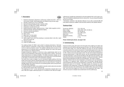
1. DescriptionGB1. Electronic temperature adjustment, continuously variable from 50°C - 450°C orwith encoder models, fixed temperatures are obtained using encoder plugs.2. Antistatic soldering iron LR-21 (24V/50W).3. High performance heating element. Insulation 500V.4. Selection of 22 WELLER "Longlife" Soldering tips.5. Temperature resistant silicon cord.6. Digital temperature display. Setting accuracy ±1 digit. Visible regulation control.7. Switching between set/actual temperature display.8. Socket for potential equalisation.9. Potentiometer locking10. Mains switch11. Mains fuse T 0.315A (5x20)12. 5 channel plug, interlocking13. Safety support rack, can be free-standing or connected either to the left or rightside of the control unit14. Cleaning sponge15. Holder for additional tips.The soldering Station <strong>EC</strong> <strong>2002</strong> is best suited for soldering electrically or thermallysensitive electronic components. A large variety of soldering tools can be connectedvia the 6 channel connection socket. The available soldering tools are given in theaccessories list. All soldering tools are electrically isolated from mains and operatewith a protective low voltage of 24V AC.Analogue temperature regulation is carried out using a potentiometer which can beused to set the temperature continuously in the range of 50°C to 450°C. The set andactual temperatures are displayed digitally. The digital temperature display can beswitched between the set and actual temperature using a slide switch. An LED illuminatesin the display to indicate the status of the temperature regulation.The mains fuse is easy to change. It can be removed by lightly pushing in the fuseholder and turning it to the left. Potential equalisation of the soldering tip can be achievedusing the corresponding connection socket on the front side of the unit. Through the<strong>antistatic</strong> design of the control unit and iron, the Soldering Station fulfils all requirementsof the EGB safety regulations.The Soldering Station <strong>EC</strong> <strong>2002</strong> is also available in encoder versions and can be convertedto a COD (encoder) version with a conversion kit.The soldering iron LR 21* comes standard with a temperature resistant silicon cordand a "WELLER Longlife" soldering tip type ET-B. The lifetime of the "WELLER Longlife"soldering tip is lengthened substantially by the electroplated finish on the copper core.There are 22 different soldering tip forms to choose from. You can choose the optimaltip from one of these.*Information contained in the Operation Manuals of any other connected WELLERtools should be observed in addition to the information contained in this Operation Manual.Technical DataDimensions (WxDxH): 115 x 150 x 94Mains voltage:230V (240V, 120V), 50 (60) HzHeating voltage:24V, 50 (60) HzSoldering iron power: max. 50W at 24VMains fuse: T 0.315ARegulation accuracy: ± 2% of final valueWeight:2.1 kgPicture: Soldering tip choices, see page 47+482. CommissioningFasten the holder spring with funnel to the foot plate of the soldering iron holder (seeexploded view) and soak the cleaning sponge with water (14). Place the soldering ironinto the safety holder (13). Insert the soldering iron plug (12) into the 6-channelconnection socket of the control unit and lock it. Connect the control unit to mains. Besure to check for the correct voltage. Set the switch for SET/ACTUAL temperature (7)to "SET". Switch on the unit at the mains switch (10) and set the desired temperatureusing the potentiometer (1). With COD versions, use the corresponding encoder plugto set the temperature. A red LED (6) illuminates to the right next to the numbers. ThisLED indicates the status of the temperature regulation. Continuous illumination": indicatesthat the actual temperature lies below the set temperature. The system is heating."Blinking" indicates that the actual temperature corresponds to the set temperature.The system is in regulation range. "Indicator does not illuminate" indicates that theactual temperature lies above the set temperature (overshoot). Set the SET/ACTUALtemperature switch (7) to "ACTUAL". The digital display (6) indicates the actualtemperature of the soldering tip. Temperature fluctuations (overshoot when heating ortemperature decrease when soldering) are also readable. When using a tip for the firsttime, once the tip has heated up, tin the end of the soldering tip with solder. Thisremoves any layers of oxidation and contaminants from the soldering tip.18<strong>EC</strong><strong>2002</strong>.pm651811.03.<strong>2002</strong>, 11:06 Uhr


