Evaluation of Organic Coatings with Electrochemical Impedance ...
Evaluation of Organic Coatings with Electrochemical Impedance ...
Evaluation of Organic Coatings with Electrochemical Impedance ...

Create successful ePaper yourself
Turn your PDF publications into a flip-book with our unique Google optimized e-Paper software.
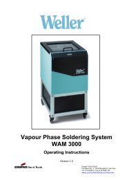
<strong>Evaluation</strong> <strong>of</strong> <strong>Organic</strong> <strong>Coatings</strong> <strong>with</strong><strong>Electrochemical</strong> <strong>Impedance</strong> SpectroscopyPart 3: Protocols for Testing <strong>Coatings</strong> <strong>with</strong> EISDavid Loveday, Pete Peterson, and Bob Rodgers—Gamry Instruments*In Parts 1 1 and 2 2 <strong>of</strong> this Series, we discussed the technology <strong>of</strong> applying electrochemicalimpedance spectroscopy (EIS) to organic coatings on a metallic substrate such as aircraft,marine, or industrial maintenance coatings. This article describes several experimental protocolsto evaluate these coatings <strong>with</strong> EIS. These experimental protocols differ primarily in theprocess used to stress the coating and accelerate the degradation <strong>of</strong> the coating.There is no standard recipe for an EIS-based evaluation program that is guaranteed towork for every coating in every environment. This may come in time and, indeed, a standardfor EIS evaluation <strong>of</strong> coatings is under development at ASTM and ISO. 3 However, EIS canbe employed in a variety <strong>of</strong> ways to evaluate virtually any coating.It may be useful to think <strong>of</strong> EIS as a very sensitive detector that provides a snapshot <strong>of</strong>coating status. However, a single EIS measurement <strong>of</strong> an organic coating tells you nothing.To measure coating lifetime or performance, the coating must be stressed to bring about itsfailure. By making periodic EIS measurements during the stress process, a rate <strong>of</strong> coatingfailure can be estimated and a series <strong>of</strong> coatings may be ranked.Even though some publications discuss the determination <strong>of</strong> the time-to-failure <strong>of</strong> a coating,this may be an unrealistic goal. There are too many variables that separate us from this“Holy Grail,” most <strong>of</strong> which are not related to EIS. A more achievable objective is to use EISin an experimental program that results in a performance ranking <strong>of</strong> a series <strong>of</strong> coatings foruse in a specific environment.The nature <strong>of</strong> the stress applied to the coating is, <strong>of</strong> course, very important in several aspects.The experimental design to prompt the failure <strong>of</strong> the coating must (1) simulate theservice environment the coating will encounter and (2) it must not change the failure mechanism.4To use EIS to evaluate a specific coating system, (1) place the coated sample in an environmentdesigned to accelerate the degradation <strong>of</strong> the coating, (2) measure the EIS curvesover time, and (3) identify an “index” that tracks coating quality. The index could be the<strong>Coatings</strong> Capacitance or the Pore Resistance, for example. The index can be very simple ormore complex and we will look at several examples in this article. Unfortunately, all coatingsdo not fail in the same way, so there is no universal index for assessing coating quality <strong>with</strong>EIS.This complex nature <strong>of</strong> coatings is no surprise to coatings scientists. A coating system mayconsist <strong>of</strong> the metal substrate, surface pretreatment, a primer, and one or more topcoats.Results can vary depending on types <strong>of</strong> coatings, thickness, number <strong>of</strong> layers, surface treatment,and the nature <strong>of</strong> the metal substrate.EXPOSURE TESTSFor the purposes <strong>of</strong> this discussion,an “exposure test” implies a testing periodequivalent to a typical standardizedcabinet or atmospheric test. This maybe as short as 15–30 days or as long asseveral years.EIS and AtmosphericExposure TestsFor the ultimate in coatings evaluation,atmospheric exposure is still the“gold standard.” Every other test is anattempt to simulate the results <strong>of</strong> atmospherictests. The problem <strong>with</strong> atmospherictests, <strong>of</strong> course, is that theyrequire a long, long time. Nothing canaccelerate the deleterious effects <strong>of</strong> atmosphericexposure, but EIS can observethe deterioration <strong>of</strong> the coatinglong before visual defects appear.Measure the EIS curve periodicallyduring the exposure period. Place thesample in contact <strong>with</strong> the electrolyte inan electrochemical cell and measure theopen-circuit potential (Eoc) as a function<strong>of</strong> time. The electrolyte can be chosento simulate the particular atmosphericconditions <strong>of</strong> the exposure test.Run the EIS experiment when the samplehas reached a steady state, signaledby a stable value <strong>of</strong> Eoc. Most computerizedEIS instruments can measure thestability <strong>of</strong> Eoc. You can run the experimentwhen the stability is better than0.1 mV/sec.Immersion and Measurement <strong>of</strong><strong>Impedance</strong> Magnitude at 0.1 HzThe most straightforward use <strong>of</strong> EISto characterize coatings is to immersethe sample in an electrolyte and periodicallymeasure the impedance spectrum.This approach is exemplified by Grayand Appleman, 5 who developed amethod to determine the barrier protectionproperties <strong>of</strong> coatings. Sampleswere immersed in 5% NaCl solution,sealed, and placed in an oven at 65°Cto accelerate attack. The panels were removedfrom the oven at 1, 4, 7, 14, and28 days and the EIS curve was run. (SeeFigure 1.)The limiting impedance at low frequencyis equal to the sum <strong>of</strong> PoreResistance (Rpore), the PolarizationResistance (Rp), and the SolutionResistance (Rs). Rp and Rpore are ini-*734 Louis Dr., Warminster, PA 18974; Voice: 215.682.9330; Fax: 215.682.9331; Email: brodgers@gamry.com.22 February 2005 JCT <strong>Coatings</strong>Tech
Analytical SeriesFigure 1—EIS response <strong>of</strong> a pipeline coating in 5% NaCl at 65°C.(Figure 8 from reference 5.)tially quite high and usually decrease<strong>with</strong> time as a result <strong>of</strong> the attack onthe coating and initiation <strong>of</strong> under-filmcorrosion. Rs is usually very low andcan be ignored. The log <strong>of</strong> the impedancemodulus at 0.1 Hz was plotted asa function <strong>of</strong> immersion time. The datasuggests that if the log <strong>of</strong> the impedancemodulus is above 7 (impedance >10 7 ohm-cm 2 ), then the coating was affordingadequate corrosion protectionto the surface. Below this impedance,the protection was poor. Above a value<strong>of</strong> 9 (impedance > 10 9 ohm-cm 2 ), theprotection is good to excellent. Thesetests were conducted on both laboratoryand field samples.Long-Term Shelf-Life TestsIn an early publication, 6 Tait detailedthe results <strong>of</strong> extended shelf-lifetests. A large population <strong>of</strong> internallycoated metal containers was aged in“typical” proprietary electrolytes at normalstorage temperatures (21°C or70°F) for longer than two years.<strong>Impedance</strong> measurements were made atperiodic intervals. The coatings fell intothree classes.In the first class, the EIS responsewas essentially that <strong>of</strong> a capacitor (seeFigure 3A <strong>of</strong> Part 2 <strong>of</strong> this series 1 ). Aftersix months, the capacitance values werevirtually the same as when the exposuretest was started. After 24 months, nocorrosion or coating delamination wasobserved upon physical examination <strong>of</strong>the samples. The constancy <strong>of</strong> the coatingcapacitance indicates little or no wateruptake in the first six months.In the second class <strong>of</strong> coatings, theEIS response closely followed the “coatingmodel” (Figure3 in Part 2 <strong>of</strong> thisseries). Tait foundthat the time-t<strong>of</strong>ailuretracked therate at which thepolarization resistancevalue in themodel dropped<strong>with</strong> time. If theRp changed rapidlyin the firstdays <strong>of</strong> exposure,the containerfailed after threemonths. Thosecontainers <strong>with</strong> aslowly changingRp lasted morethan two years.In the third class <strong>of</strong> coatings, the EISresponse was also similar to that <strong>of</strong> the“coating model.” However, another circuitelement, the Warburg <strong>Impedance</strong>that models diffusion, was required t<strong>of</strong>it the data. In this class, the fraction <strong>of</strong>delaminated coating was found to trackthe rate at which the coating capacitance,Ccoating, changed over the fourmonthtest period.EIS and Cabinet TestsThe most common testing techniquefor coatings is exposure to a series <strong>of</strong>controlled aggressive conditions in acabinet constructed for this purpose.The conditions include a variety <strong>of</strong>chemistries as well as exposure to UVradiation and cycles <strong>of</strong> wetness/drynessand heat/cold. These cabinets have beenin common use for decades and attemptto simulate atmospheric or industrialconditionsthat can be used todegrade the coatingin a realistic fashion.The goal is to correlatecabinet tests<strong>with</strong> actual exposuretests to predict timeto-failure.It is generallyaccepted thatcabinet tests providecomparative resultsand not absolute results.When used <strong>with</strong>cabinet tests, EIS actsas a quantitative detector<strong>of</strong> coatingsquality. The EIS response<strong>of</strong> a sampleundergoing cabinet tests will follow thegeneral trend described in Figure 3 <strong>of</strong>Part 2 in this series. 2 An EIS experimentis conducted on the specimens in thecabinet on a regular basis. If the samplesare deteriorating rapidly, the EIScurves should be run daily. For moredurable paints, a weekly EIS evaluationmay be sufficient.Some <strong>of</strong> the more popular cabinettests are ASTM B 117 Salt Spray, ASTMD 5894 Cyclic Salt Fog/UV Exposure,and SAE J2234 Laboratory CyclicCorrosion Test. The cabinet test standardsspecify the conditions for exposurein the cabinet, but do not providetesting methods or pass-fail criteria.This is addressed in ASTM D 1654,“<strong>Evaluation</strong> <strong>of</strong> Painted or CoatedSpecimens Subjected to CorrosiveEnvironments.” All <strong>of</strong> these testing protocolsare qualitative in nature.Coupling EIS <strong>with</strong> these standard cabinettests can provide a quantitativemeasure <strong>of</strong> coating deterioration.ASTM D 1654 discusses both scribedand unscribed panels. A scribed panel isgenerally used to simulate major damageto the coating that exposes the substrate-coatinginterface. The loss <strong>of</strong> adhesionis quantitated by measuring thelength <strong>of</strong> “creepage” <strong>of</strong> the paint filmfrom the scribe after air blow-<strong>of</strong>f orscraping. Adhesion may also be measured<strong>with</strong> a tape pull-<strong>of</strong>f test (ASTM D3359). Tests on a scribed panel do notmeasure the barrier properties <strong>of</strong> thecoating; they measure the ability <strong>of</strong> thecoating-substrate to self-repair when thesubstrate is exposed.The Knife Adhesion Test in ASTM D6677 tests the adhesion <strong>of</strong> the coatingon an unscribed sample, usually after aFigure 2—Reversible behavior <strong>of</strong> a coating during thermal cycling.Open circles indicate heating, closed circles indicate cooling. (Figure6 from reference 9.)www.coatingstech.orgFebruary 2005 23
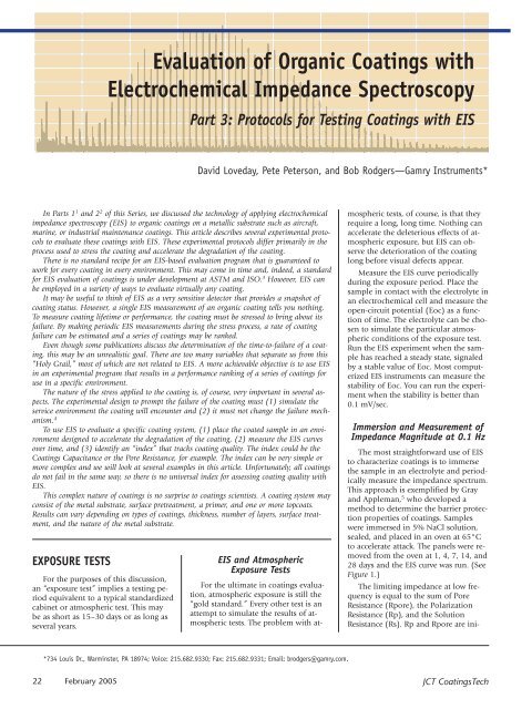
Figure 3—Irreversible behavior <strong>of</strong> a coating during thermal cycling.Open circles indicate heating, closed circles are cooling. (Figure 8from reference 9.)controlled exposure <strong>of</strong> some sort. Thereis a fundamental difference betweenpulling the coating <strong>of</strong>f <strong>with</strong> tape andlifting the coating <strong>with</strong> a knife, andsome workers prefer the latter.An unscribed panel is used to test forrusting (ASTM D 610), blistering (ASTMD 714), or adhesion (ASTM D 3359)through the coating. Both D 610 and D714 provide a semi-quantitative rankingtechnique involving the comparison <strong>of</strong>the tested panel to a series <strong>of</strong> photographs.The quantitative numerical resultsfrom EIS are seen as a major technicaladvancement in this area.Since one <strong>of</strong> the key advantages <strong>of</strong>EIS is the ability to simultaneouslymeasure the barrier properties and thecorrosion properties, scribed panels arerarely used <strong>with</strong> EIS. The scribe inflictsphysical damage to the paint film andunderlying substrate and contributes topoor reproducibility. 7ASTM B 117 Salt Spray is the oldeststandard cabinet test and, therefore, thetest <strong>with</strong> the most history. B 117 is usedto test bare metals and painted metals.With regard to painted metals, historyhas not been kind to ASTM B 117 andmost users accept that B 117 does notcorrelate well <strong>with</strong> actual exposure.Nevertheless, it is still in common use,particularly for quality control applicationsor comparing different materials.ASTM B 117 uses a salt fog <strong>of</strong> 5% NaClto accelerate the natural corrosionprocess.Based on comments from <strong>with</strong>in theindustry, ASTM B 117 is not consideredto be a useful technique for evaluatingcoatings and its use <strong>with</strong> EIS is not recommended.ASTM D 5894Cyclic Salt Fog/UVExposure <strong>of</strong> PaintedMetal differs fromB 117 in three keyfactors: UV exposure,more dilutesalt solution, andwet/dry cycles. Theintense UV radiationat 340 nmphotochemicallydegrades the coatingand is a key factorin simulatingexposure in exteriorconditions. The wetand dry cycles providerealistic conditionsfor corrosion.The test involves:• A one-week (168 hr) exposure cycle<strong>of</strong> 4-hr UV at 60°C and 4-hrcondensation at 50°C followedby:• A one-week (168 hr) fog/dry cycle<strong>of</strong> 1-hr fog (0.05% NaCl and0.35% NH 4SO 4) at ambient temperatureand 1-hr dry-<strong>of</strong>f at 35°C.• The cycles may be repeated ifagreed by the parties involved.ASTM D 5894, unlike B 117, was developedspecifically for coatings and isgenerally agreed to give more realisticresults. These results, however, are comparativeand not absolute. ASTM D5894 is also referred to as a ProhesionTest, from “Protection by Adhesion.”ASTM D 5894 has enjoyed wide acceptanceby the coatings community.Bierwagen 4 recommends the use <strong>of</strong> D5894 <strong>with</strong> weekly EIS analysis to trackthe status <strong>of</strong> the coating.To employ EIS as a quantitative sensor<strong>of</strong> coating degradation during D5894, remove the panel from the fog cycle,immerse the panel in an electrolyte<strong>of</strong> 0.05% NaCl and 0.35% NH 4SO 4, allowthe sample to equilibrate for30 min, then run the EIS curve. Toobtain the most consistent results,the samples should be removedfrom the cabinet at the samepoint in the cycle. If possible, coordinatemultiple panels so theyare outside <strong>of</strong> the cabinet for thesame amount <strong>of</strong> time.SAE J2334 Laboratory CyclicCorrosion Test 8 was developed bythe automotive and steel industryspecifically for automotive coatingsand is widely used by boththe automobile manufacturers and theirvendors. The development involvedcomparing several different test conditionson standard panels that had beenexposed to an urban industrial environmentfor five years. The test conditionsthat gave the best correlation to the exposuretests were selected. The conditions<strong>of</strong> J2334 were selected primarilyto simulate the effects <strong>of</strong> road salts. It isinteresting that J2334 does not employUV exposure.One 24-hr cycle <strong>of</strong> SAE J2334 consists<strong>of</strong> three stages:• Humid Stage—50°C and 100%relative humidity for 6 hr.• Salt Application Stage—Dip, fog,or spray a salt solution (0.5%NaCl, 0.1% CaCl 2, 0.075%NaHCO 3) for 15 min.• Dry Stage—60°C and 50% relativehumidity for 17 hr, 45 min.The typical SAE J2334 test is conductedfor 60 cycles for coated samples.The test allows for either manual or automaticoperation. Because SAE J2334was developed for a relatively specificsample, there is a correlation to actualexposure time: 80 cycles <strong>of</strong> SAE J2334corresponds to about five years <strong>of</strong> exposure.ACCELERATED TESTSEven though a cabinet test is fasterthan real-world exposure, it still takes along time. One cycle <strong>of</strong> ASTM D 5894requires two weeks. One cycle <strong>of</strong> SAEJ2334 takes 24 hours and the normaltest requires 60 cycles, or two months!Since nothing is ever fast enough, severalattempts have been made to developquicker tests for paints. Theseshort-term tests introduce more aggressivestress conditions to induce failurein a shorter time. The user <strong>of</strong> the acceleratedtests must be concerned that (1)Figure 4—Equivalent circuit used in the REAP procedure.The Constant Phase Element is indicated by . O24 February 2005 JCT <strong>Coatings</strong>Tech
Analytical Seriesthe stress method does not change themechanism <strong>of</strong> failure and (2) the stressmethod is sufficiently analogous to theservice conditions to be relevant. Theultimate goal is a short test that producesa predictive result.Thermal CyclingBierwagen 9 has investigated the acceleration<strong>of</strong> coatings failure by hightemperature. An increase in temperaturewill increase the rate <strong>of</strong> diffusion <strong>of</strong> theelectrolyte into the coating, reducingthe barrier properties <strong>of</strong> the coating andpossibly enhancing the chemical andphysical “aging effects” from attack bythe electrolyte.The sample is immersed in the electrolyte(0.05% NaCl and 0.35%NH 4SO 4) from ASTM D 5894. An EIScurve is obtained at room temperature,35º, 55º, 75º, and 85ºC, then in thesame sequence back to room temperature.The EIS data is obtained at eachtemperature after equilibrating for 20min. A complete test procedure consists<strong>of</strong> three temperature cycles, followed bya three-day immersion, and a final EISscan. A complete test period requiresabout one week. To obtain similar results<strong>with</strong> a Prohesion Test may require4–12 weeks.The behavior <strong>of</strong> the EIS curves duringthe thermal excursions provides anindication <strong>of</strong> coating quality and corrosionresistance. As the temperature is increased,the total impedance at low frequenciesis reduced. When the sampleis cooled, the low frequency impedancemay (Figure 2), or may not (Figure 3),return to its original value. The return <strong>of</strong>the impedance at low frequency to itsinitial value is an indication <strong>of</strong> good corrosionresistance <strong>of</strong> the coated sample.If the temperature range <strong>of</strong> the thermalcycling test includes the glass transitiontemperature (T g), it might be wiseto run two tests: one that remains belowT gand another that incorporatesthe normal temperature limits.Rapid <strong>Electrochemical</strong>Assessment <strong>of</strong> Paint (REAP)In 1996, Kendig and coworkers publishedan electrochemical approach to a24-hour determination <strong>of</strong> the time-t<strong>of</strong>ailure<strong>of</strong> an automotive coating onmild steel. 10 The Rapid <strong>Electrochemical</strong>Assessment <strong>of</strong> Paint (REAP) protocol incorporatesan impedance measurementwww.coatingstech.orgto determine thebarrier properties<strong>of</strong> the coating anda cathodic disbondingprocedureto determine thedamage caused bycorrosion at themetal-paint interface.To our knowledge,the REAP testis the only publishedprocedure tocombine an EISmeasurement <strong>with</strong>a physical test forpaint adhesion.The EIS measurementswere performedin 0.5 MNaCl. The impedancewas measuredimmediately afterimmersion andagain after 24 hr.Although a frequencysweep from10 4 to 0.1 Hz issufficient to characterizethe sampleinitially, a lowerfrequency <strong>of</strong> 0.01Hz is needed forthe later scan. Thelower frequency isnecessary to definethe EIS curve afterthe development <strong>of</strong>a Pore Resistanceand a Polarization Resistance.The equivalent circuit shown inFigure 4 was used to model the system.Notice that the authors chose to use aConstant Phase Element (CPE) instead<strong>of</strong> a capacitor to model the coatingmetalinterface. A CPE has been describedas an “imperfect capacitor” andis mathematically expressed as:Zcpe = (1/Y 0)/ (jω) αY 0is a constant, j = (–1) ½ , ω = 2πf, andα is a constant between 0 and 1. If α =1, Y 0is the capacitance. The use <strong>of</strong> theCPE as an element in the equivalent circuitis left to the discretion <strong>of</strong> the user.Use <strong>of</strong> a CPE can sometimes give a betterfit <strong>with</strong> a model. Even though theCPE does not have a simple explanation,it is relatively popular in the electrochemicalliterature.The cathodic disbonding experimentis performed on a second identical sample.The sample is scribed through theFigure 5a—<strong>Impedance</strong> response <strong>of</strong> an epoxy coating on steel to theAC-DC-AC procedure. (Figure 3 from reference 12.)Figure 5b—Phase response <strong>of</strong> an epoxy coating on steel to the AC-DC-AC procedure. (Figure 3 from reference 12.)paint to expose the underlying metal.The scribed sample is immersed in 0.5M NaCl and a potential <strong>of</strong> -1050 mV isapplied for 24 hr. The primary reactionis the reduction <strong>of</strong> oxygen.O 2+ 4e – + 2H 2O → 4OH –The alkaline environment producedby the cathodic reaction is particularlydetrimental to the adhesion <strong>of</strong> the coatingto the metal. The coating is furtherstressed by the oxidation <strong>of</strong> the metal(usually iron) to the oxides, which havea higher volume than the base metal.After completion <strong>of</strong> the cathodic polarization,delamination <strong>of</strong> the coatingis measured by placing tape across thescribe and pulling to remove the portion<strong>of</strong> the coating that has disbonded.The goal <strong>of</strong> the REAP technique isambitious, since the authors not onlyhad to define the parameters to predicttime-to-failure, they also had to definetime-to-failure itself, a not insignificantFebruary 2005 25
Figure 6—EIS response <strong>of</strong> a free PVC plastisol film during immersionin 3% NaCl. (Figure 2 from reference 13.)The concept <strong>of</strong> combining EIS tomeasure the barrier properties andmore conventional physical techniquesto evaluate adhesion is attractive tomany researchers. The consensus seemsto be that barrier properties and adhesionare both important, but very different.Since adhesion is a function <strong>of</strong>chemical, electrochemical, and physicalproperties, EIS may not alwaysserve to evaluate adhesion. In additionto the tape pull-back test, adhesion canbe tested <strong>with</strong> ASTM D 6677 (KnifeAdhesion Test). It can also be useful tocombine cathodic disbonding <strong>with</strong>tests such as D 6677. In the case <strong>of</strong> D6677, cut the coating <strong>with</strong> the knife,then apply a potential <strong>of</strong> about –1 voltvs. SCE to encourage cathodic disbonding.Assess the disbondingas describedin D 6677.contacting the sample using a copperdisk and filter paper moistened <strong>with</strong> theappropriate electrolyte.task that, regardless <strong>of</strong> the definition, iscertain to attract critics. ASTM B 117 saltfog was chosen as the accelerated test,not so much for its successful prediction<strong>of</strong> lifetimes, but because <strong>of</strong> itswidespread use in the coatings industry.The best correlation was obtained byusing Rcor, % water uptake, and pullback(dx/dt) to estimate time-to-failure.Note that Rcor and Rp are identical.TTF = –830.1 + 118 log Rcor – 169.2 logdx/dt – 48.03 (%water)The water uptake was calculated bymeasuring the initial EIS spectrum andagain after 24 hr. Coating capacitances(C) were evaluated from the EIS measurements.Volume fraction <strong>of</strong> water =Log (Ct/Co)Log 80AC-DC-ACThe AC-DC-ACtest employs EIS toobserve the condition<strong>of</strong> the coatingbefore and after anelectrochemical disbondingstep. 11,12The test consists <strong>of</strong>three steps: (1) anEIS curve is run toestablish the initialcondition <strong>of</strong> thecoating; (2) thesample is cathodicallypolarized to generate an alkalineenvironment and stimulate delamination;and (3) an EIS curve is run to assessthe condition <strong>of</strong> the coating afterdelamination. Steps 2 and 3 may be repeatedto apply additional stress to thesample if desired (Figure 5).The cathodic potential (a negativepotential is termed “cathodic” becauseit prompts a reduction reaction) generateshydrogen and hydroxide ions at thesurface <strong>of</strong> the metal beneath the coating.H 2O + e – → H 2+ OH –The adhesion <strong>of</strong> the coating is compromisedby the alkaline environmentand delamination is further encouragedby the pressure <strong>of</strong> the hydrogen beneaththe coating.For fresh, intact coatings, it is necessaryto apply a pronounced negativepotential (from –2 to –3 volts) to inducea stress. Based on the interpretation<strong>of</strong> the structure <strong>of</strong> a paint film ona metallic substrate, the cathodic polarizationstep must attack the coating byopening pores, allowing access to themetal surface. From the EIS response tothis applied stress, that is exactly whatis happening as noted by the reductionin the limiting impedance at low frequency.The AC-DC-AC test can be conductedon a paint panel in a typicalthree-electrode electrochemical cell. Ithas also been successfully employed onroutine samples or on samples outside<strong>of</strong> the laboratory by using the EIS instrumentin “two-electrode mode” andSTUDIES OF FREEPAINT FILMSThe effect <strong>of</strong> the paint film can beseparated from effects <strong>of</strong> the metal substrateor the metal-paint interface bystudying the free paint films. The freefilms can be produced by applying toglass, plastic, or smooth metal and carefullyremoving. The free films aremounted in an electrochemical cell thatallows an electrolyte to be placed on eitherside <strong>of</strong> the film. The EIS curve isgenerated using a “four-terminal” or“four-electrode” measurement, in whicha reference electrode and an inert electrode(usually platinum) are placed oneither side <strong>of</strong> the membrane.Permeation <strong>of</strong> the coating <strong>with</strong> ionsor water can be precisely studied <strong>with</strong>free films. 13,14 The changes in impedance<strong>of</strong> a free film after immersion aresimilar to the changes observed in coatingsapplied to substrates, but they occurfaster. The EIS response typicallydisplays a decrease in impedance andan increase in capacitance as water penetratesthe film (see Figure 6).PRACTICAL ISSUESEIS and Coating ThicknessA newcomer to EIS may have concernsregarding the maximum coatingthickness that can be measured. Thethickness <strong>of</strong> the coating is not the issue;the impedance <strong>of</strong> the coating is the figure<strong>of</strong> merit. Thickness is immaterial.For example, a two-inch filled polymericcoating on the high-strength steelhull <strong>of</strong> an ocean-going vessel can beevaluated using EIS. The impedance isabout 10 13 ohms-cm 2 , which is veryhigh. The EIS measurement was assistedby using a 12 in. 2 sample.Precision <strong>of</strong> EIS MeasurementsTo have confidence in a scientificmeasurement, it is important to understandthe accuracy and precision <strong>of</strong> themeasurement. The accuracy and precision<strong>of</strong> modern EIS instrumentation is26 February 2005 JCT <strong>Coatings</strong>Tech
Analytical Seriestypically ±1% for impedances between1 and 10 megaohms at frequencies between10 µHz and 100 kHz. For organiccoatings <strong>with</strong> impedances higher than10 Mohms (10 7 ohms), the user shouldconfirm that the EIS instrument is capable<strong>of</strong> proper operation in this impedanceregion by running an Open LeadCurve. (See Part 1 <strong>of</strong> this Series.)The greatest source <strong>of</strong> error is thevariation in coating thickness. This variationcan occur on the surface <strong>of</strong> an individualsample and from sample-tosampleand can be remarkably high.These issues are discussed for coatedaerosol containers by Tait. 15 When dealing<strong>with</strong> sample variability, it is best toincrease the number <strong>of</strong> sample replications.Tait recommends eight replicatesfor coated samples.Cable LengthIn the field, the sample can be a longdistance from the EIS instrument. Thisis particularly true for towers, aircraft, orwatercraft. This requires the use <strong>of</strong> longcables that, because <strong>of</strong> the additionalcapacitance they add to the system, cancause serious problems <strong>with</strong> noise pickup.Cable length should be kept asshort as possible. In the event that extendedcables are required, seek the advice<strong>of</strong> the manufacturer and, if possible,purchase the cables from themanufacturer. In spite <strong>of</strong> this potentialproblem, EIS measurements have beensuccessfully performed on an aircraft inan operating hangar <strong>with</strong> 80-ft (25 m)cables on aircraft coatings <strong>with</strong> impedancesas high as 10 11 ohms.FUTURE DIRECTIONSEIS is a unique measurement tool inthat it provides a quantitative test onthe complete coating system (metal substrateand coating). We expect that thesteady proliferation <strong>of</strong> EIS into the coatingscommunity will lead to a greaterunderstanding <strong>of</strong> the breadth <strong>of</strong> applicationsto various coatings. Within generalclasses <strong>of</strong> coatings, it is likely thatfailure mechanisms will be classifiedand routinized.The need for more rapid results willdrive the continued development <strong>of</strong> acceleratedtests. To incorporate delaminationinto testing procedures, the combination<strong>of</strong> EIS and adhesion testing willprobably be exploited. As EIS gains acceptabilityby coatings researchers, therewill be a need for multichannel instrumentsfor greater sample throughput atlower cost. If cabinet tests remain popular,there will be a demand for automatedEIS measurements during the exposureperiod.ACKNOWLEDGMENTSThe authors thank the following colleaguesfor their input and discussion:Gordon Bierwagen and Vicki Gelling(North Dakota State University),Richard Granata (Florida AtlanticUniversity), Linda Gray (KTA-Tator),Lingyun He (General Electric Corp.),Jochen Hollaender (Fraunh<strong>of</strong>erInstitute), Yuly Korobov (Carboline),Larry Laliberte (ConcurrentTechnologies), Martin Kendig (RockwellScientific), Oscar Mattos (FederalUniversity <strong>of</strong> Rio de Janeiro), AldaSimoes (Instituto Superior Tecnico),Brian Skerry (Sherwin-Williams), JulioSuay (Castellon University), and MarcWirtz (PPG Industries). CTReferences(1) Loveday, D., Peterson, P., and Rodgers, B.,“<strong>Evaluation</strong> <strong>of</strong> <strong>Organic</strong> <strong>Coatings</strong> <strong>with</strong><strong>Electrochemical</strong> <strong>Impedance</strong> Spectroscopy:Fundamentals <strong>of</strong> <strong>Electrochemical</strong><strong>Impedance</strong> Spectroscopy,” JCTCOATINGSTECH, 1, No. 8, p. 46 (August2004).(2) Loveday, D., Peterson, P., and Rodgers, B.,“<strong>Evaluation</strong> <strong>of</strong> <strong>Organic</strong> <strong>Coatings</strong> <strong>with</strong><strong>Electrochemical</strong> <strong>Impedance</strong> Spectroscopy:Application <strong>of</strong> EIS to <strong>Coatings</strong>,” JCTCOATINGSTECH, 1, No. 10, p. 88 (October2004).(3) ISO TC 35 SC9 WG 29/ASTM D01.27.32.Standard Practice for Performing<strong>Electrochemical</strong> <strong>Impedance</strong> Spectroscopy(EIS) on High <strong>Impedance</strong> CoatedSamples. Expected publication in Spring2005.(4) Bierwagen, G., Tallman, D., Li, J., and He,L., “EIS Studies <strong>of</strong> Coated Metals inAccelerated Exposure,” Prog. Org. Coat., 46,148 (2003).(5) Gray, L. and Appleman, B., “<strong>Electrochemical</strong><strong>Impedance</strong> Spectroscopy: A Tool toPredict Remaining Coating Life,” J. Prot.Coat. Linings, p. 66, February 2003.(6) Tait, W.S., “Using <strong>Electrochemical</strong><strong>Impedance</strong> Spectroscopy to StudyCorrosion Behavior <strong>of</strong> Internally CoatedMetal Containers,” JOURNAL OF COATINGSTECHNOLOGY, 61, No. 768, 57 (1989).(7) Yasuka, H.K. et al., “Effect <strong>of</strong> ScribingMode on Corrosion Test Results,”Corrosion, 57, 29 (2001).(8) Society <strong>of</strong> Automotive Engineers, 400Commonwealth Dr., Warrendale, PA15096-0001 USA; web: www.sae.org;phone: 724-776-4970.(9) Bierwagen, G.P., He, L., Li, J., Ellingston,L., and Tallman, D.E., “Studies <strong>of</strong> NewAccelerated <strong>Evaluation</strong> Method forCoating Corrosion Resistance—ThermalCycling Testing,” Prog. Org. Coat., 39, 67(2000).(10) Kendig, M., Jeanjaquet, S., Brown, R., andThomas, F., “Rapid <strong>Electrochemical</strong>Assessment <strong>of</strong> Paint,” JOURNAL OF COATINGSTECHNOLOGY, 68, No. 863, 39 (1996).(11) Hollaender, J., Food Additives andContaminants, 14, 617 (1997).(12) Suay, J.J. et al., “Rapid Assessment <strong>of</strong>Automotive Epoxy Primers by<strong>Electrochemical</strong> Techniques,” JOURNAL OFCOATINGS TECHNOLOGY, 75, No. 946, 103(2003).(13) Castela, A.A. and Simoes, A.M., “WaterSorption in Freestanding PVC Films byCapacitance Measurements,” Prog. Org.Coat., 46, 130 (2003).(14) Mattos, O.R. and Margarit, I.C.P., “About<strong>Coatings</strong> and Cathodic Protection:Properties <strong>of</strong> the <strong>Coatings</strong> InfluencingDelamination and Cathodic ProtectionCriteria,” Electrochimica Acta, 44, 84(2003).(15) Tait, W.S., “Using <strong>Electrochemical</strong>Measurements to Estimate <strong>Coatings</strong> andPolymer Film Durability,” JOURNAL OFCOATINGS TECHNOLOGY, 75, No. 942, 45(2003).www.coatingstech.orgFebruary 2005 27