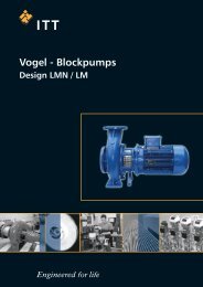
LSB german_french_english 771076129 - Water Solutions
LSB german_french_english 771076129 - Water Solutions
LSB german_french_english 771076129 - Water Solutions

You also want an ePaper? Increase the reach of your titles
YUMPU automatically turns print PDFs into web optimized ePapers that Google loves.
de VOGEL-SpiralgehäusepumpenBaureihe: <strong>LSB</strong>Einbau-, Betriebs- und WartungsanleitungOriginalbetriebsanleitungfrenVOGEL-Pompes à voluteSérie: <strong>LSB</strong>VOGEL-Volute Casing PumpsModel: <strong>LSB</strong>Instructions de montage, de service et de maintenanceTraduction de la notice d’exploitation originaleInstallation, Operation and Maintenance InstructionTranslation of the Original Operation ManualdefrenFür künftige Verwendung aufbewahren !Diese Betriebsanleitung vor dem Transport, dem Einbau, der Inbetriebnahme usw. genau beachten!Conserver soigneusement ces instructions pour consultations ultérieures !Lire attentivement ces instructions de service avant le transport, le montage, la mise en service etc. !Keep for further use !Pay attention to this operating instruction before the delivery, installation, start-up a.s.o.!Artikel Nr. <strong>771076129</strong> Rev. 02 01/2012
EG-Konformitätserklärung (nur gültig für komplette von Xylem <strong>Water</strong> <strong>Solutions</strong> Austria GmbH gelieferteAggregate)(gemäß EG-Maschinenrichtlinie 2006/42/EG Anhang II A)Hiermit erklärt der Hersteller:Xylem <strong>Water</strong> <strong>Solutions</strong> Austria GmbHErnst Vogel-Strasse 22000 StockerauAustriader Pumpenaggregate der Baureihe<strong>LSB</strong>40-25-160, <strong>LSB</strong>40-25-200, <strong>LSB</strong>40-25-250, <strong>LSB</strong>50-32-160, <strong>LSB</strong>50-32-200, <strong>LSB</strong>50-32-250,<strong>LSB</strong>50-32-315, <strong>LSB</strong>65-40-160, <strong>LSB</strong>65-40-200, <strong>LSB</strong>65-40-250, <strong>LSB</strong>65-40-315, <strong>LSB</strong>80-50-160,<strong>LSB</strong>80-50-200, <strong>LSB</strong>80-50-250, <strong>LSB</strong>80-50-315, <strong>LSB</strong>100-65-160, <strong>LSB</strong>100-65-200, <strong>LSB</strong>100-65-250,<strong>LSB</strong>100-65-315, <strong>LSB</strong>125-80-160, <strong>LSB</strong>125-80-200, <strong>LSB</strong>125-80-250, <strong>LSB</strong>125-80-315, <strong>LSB</strong>125-100-200, <strong>LSB</strong>125-100-250, <strong>LSB</strong>125-100-315, <strong>LSB</strong>150-125-250, <strong>LSB</strong>150-125-315, <strong>LSB</strong>200-150-250Die gelieferten Aggregate entsprechen den einschlägigen Bestimmungen der EG-Maschinenrichtlinie2006/42/EG.Die mitgelieferten Drehstrommotore entsprechen den Bestimmungen der Richtlinie 2004/108/EG.Die speziellen technischen Unterlagen nach Anhang VII A wurden erstellt.Ich werde der zuständigen Behörde gegebenenfalls die vorgenannten speziellen technischen Unterlagen inelektronischer Form auf Datenträgern übermitteln.Die vorgenannten speziellen technischen Unterlagen können angefordert werden beiDipl.Ing. Gerhard FaschingAbtlg. Research & DevelopmentXylem <strong>Water</strong> <strong>Solutions</strong> Austria GmbHErnst Vogel-Strasse 22000 StockerauAustriaAngewendete harmonisierte Normen, insbesondereEN 809 :1998+A1:2009+AC:2010(D)EN 953 :1997+A1:2009(D)EN ISO 12100 :2010(D)EN 60204-1 :2006/A1:2009 DBei einer nicht mit uns abgestimmten Veränderung des Aggregates verliert diese Erklärung ihre Gültigkeit,ebenso wenn das Aggregat in Anlagen eingebaut wird, bei denen keine Konformitätserklärungentsprechend Maschinenrichtlinie 2006/42/EG vorliegt.Stockerau, 09.01.2012 ................................................................................................Dir. Peter SteinbachProduction manager
Déclaration CE de conformité (valable uniquement pour les agrégats complets, fournis par la sociétéXylem <strong>Water</strong> <strong>Solutions</strong> Austria GmbH)(en vertu de la Directive 2006/42/CE relatives aux machines, annexe II A)Par la présente,Xylem <strong>Water</strong> <strong>Solutions</strong> Austria GmbHErnst Vogel-Strasse 22000 StockerauAustriafabricant de groupes de pompage de série type déclare :<strong>LSB</strong>40-25-160, <strong>LSB</strong>40-25-200, <strong>LSB</strong>40-25-250, <strong>LSB</strong>50-32-160, <strong>LSB</strong>50-32-200, <strong>LSB</strong>50-32-250,<strong>LSB</strong>50-32-315, <strong>LSB</strong>65-40-160, <strong>LSB</strong>65-40-200, <strong>LSB</strong>65-40-250, <strong>LSB</strong>65-40-315, <strong>LSB</strong>80-50-160,<strong>LSB</strong>80-50-200, <strong>LSB</strong>80-50-250, <strong>LSB</strong>80-50-315, <strong>LSB</strong>100-65-160, <strong>LSB</strong>100-65-200, <strong>LSB</strong>100-65-250,<strong>LSB</strong>100-65-315, <strong>LSB</strong>125-80-160, <strong>LSB</strong>125-80-200, <strong>LSB</strong>125-80-250, <strong>LSB</strong>125-80-315, <strong>LSB</strong>125-100-200, <strong>LSB</strong>125-100-250, <strong>LSB</strong>125-100-315, <strong>LSB</strong>150-125-250, <strong>LSB</strong>150-125-315, <strong>LSB</strong>200-150-250 Les groupes fournis répondent aux dispositions afférentes de la Directive 2006/42/CE relative auxmachines. Les moteurs triphasés qui sont livrés avec ces groupes répondent aux dispositions afférentes de laDirective 2004/108/CE relative à la basse tension. Un dossier technique spécial a été établi en vertu de l’annexe VII A. Je mettrai éventuellement le dossier technique susmentionné à la disposition des autorités compétentes etce, sous format électronique, sur un support de stockage de données. Le dossier technique susmentionné peut être demandé à l’adresse suivante :Dipl.Ing. Gerhard FaschingAbtlg. Research & DevelopmentXylem <strong>Water</strong> <strong>Solutions</strong> Austria GmbHErnst Vogel-Strasse 22000 StockerauAustria Normes harmonisées appliquées – principalement :EN 809 :1998+A1:2009+AC:2010(D)EN 953 :1997+A1:2009(D)EN ISO 12100 :2010(D)EN 60204-1 :2006/A1:2009 DSi une modification qui n’a pas été approuvée de notre part est effectuée sur le groupe, la présentedéclaration n’est plus valable. Ceci est également le cas lorsque le groupe est incorporé dans desmachines pour lesquelles il n’existe aucune déclaration de conformité en vertu de la Directive 2006/42/CErelative aux machines.Stockerau, 09.01.2012 ................................................................................................Dir. Peter SteinbachProduction manager
EC Declaration of Conformity (valid only for Xylem <strong>Water</strong> <strong>Solutions</strong> Austria GmbH aggregate supplied in itsentirety)(according to EC Directive on Machinery 2006/42/EC, Annex II A)The manufacturer,Xylem <strong>Water</strong> <strong>Solutions</strong> Austria GmbHErnst Vogel-Strasse 22000 StockerauAustriaof the pumps from the standard product line hereby declares:<strong>LSB</strong>40-25-160, <strong>LSB</strong>40-25-200, <strong>LSB</strong>40-25-250, <strong>LSB</strong>50-32-160, <strong>LSB</strong>50-32-200, <strong>LSB</strong>50-32-250,<strong>LSB</strong>50-32-315, <strong>LSB</strong>65-40-160, <strong>LSB</strong>65-40-200, <strong>LSB</strong>65-40-250, <strong>LSB</strong>65-40-315, <strong>LSB</strong>80-50-160,<strong>LSB</strong>80-50-200, <strong>LSB</strong>80-50-250, <strong>LSB</strong>80-50-315, <strong>LSB</strong>100-65-160, <strong>LSB</strong>100-65-200, <strong>LSB</strong>100-65-250,<strong>LSB</strong>100-65-315, <strong>LSB</strong>125-80-160, <strong>LSB</strong>125-80-200, <strong>LSB</strong>125-80-250, <strong>LSB</strong>125-80-315, <strong>LSB</strong>125-100-200, <strong>LSB</strong>125-100-250, <strong>LSB</strong>125-100-315, <strong>LSB</strong>150-125-250, <strong>LSB</strong>150-125-315, <strong>LSB</strong>200-150-250 The supplied aggregates meet the relevant regulations of the EC Directive on Machinery, 2006/42/EC The three-phase electric motor supplied at the same time meets the relevant regulations of Directive2004/108/EC. Special technical documentation has been prepared, in accordance with Annex VII A. If necessary, we can submit the above-listed special technical documentation, in electronic form on a datastorage medium, to the relevant authorities. The above-listed special documentation can be requested at the following address:Dipl. Ing. Gerhard FaschingAbtlg. Research & DevelopmentXylem <strong>Water</strong> <strong>Solutions</strong> Austria GmbHErnst Vogel-Strasse 22000 StockerauAustriaAmong others, the following harmonised standards have been applied:EN 809 :1998+A1:2009+AC:2010(D)EN 953 :1997+A1:2009(D)EN ISO 12100 :2010(D)EN 60204-1 :2006/A1:2009 DA change to an aggregate which was not approved by us invalidates this declaration. This also applies inthe case that the aggregate is installed in equipment that does not have the declaration of conformity inaccordance with the Directive on Machinery, 2006/42/EC.Stockerau, 09.01.2012 ................................................................................................Dir. Peter SteinbachProduction manager
Einbau-, Betriebs- und WartungsanleitungBaureihe <strong>LSB</strong>Leistungsschild der Pumpe......................................... 2ATEX-Schild (nur für Pumpen entsprechend 94/9/EG).................................................................................... 21. Allgemeines ............................................................ 31.1 Gewährleistung ................................................. 32. Sicherheitshinweise ................................................ 32.1 Kennzeichnung von Hinweisen in derBetriebsanleitung..................................................... 32.2 Gefahren bei Nichtbeachtung derSicherheitshinweise................................................. 42.3 Sicherheitshinweise für den Betreiber / Bediener................................................................................ 42.4 Sicherheitshinweise für Wartungs-, InspektionsundMontagearbeiten .............................................. 42.5 Eigenmächtiger Umbau undErsatzteilherstellung................................................ 42.6 Unzulässige Betriebsweisen ............................. 42.7 Explosionsschutz............................................... 52.8 Bestimmungsgemäße Verwendung.................. 63. Ausführungsbeschreibung...................................... 63.1 Bauart................................................................ 63.1.1 Bezeichnungsschema .................................... 73.2 Wellenabdichtung.............................................. 73.3 Lagerung ........................................................... 73.4 Richtwerte für Schalldruckpegel........................ 73.5 Zulässige Stutzenkräfte und Momente an denPumpenstutzen ... ................................................... 73.6 Zulässige Drücke und Temperaturen................ 83.7 Kondenswasser................................................. 94. Transport, Handhabung, Zwischenlagerung........... 94.1 Transport, Handhabung .................................... 94.2 Zwischenlagerung / Konservierung................... 95. Aufstellung / Einbau................................................ 95.1 Aufstellung des Aggregates .............................. 95.2 Anschluss der Rohrleitungen an die Pumpe... 105.3 Antrieb............................................................. 105.4 Elektrischer Anschluss.................................... 115.5 Endkontrolle .................................................... 116. Inbetriebnahme, Betrieb, Außerbetriebnahme...... 116.1 Erstinbetriebnahme ......................................... 116.2 Antriebsmaschine einschalten. ....................... 116.3 Wiederinbetriebnahme.................................... 116.4 Grenzen des Betriebes.................................... 11INHALTSVERZEICHNIS6.5 Schmierung .....................................................126.6 Überwachung...................................................126.7 Außerbetriebnahme.........................................126.8 Zwischenlagerung / Längerer Stillstand...........127. Instandhaltung, Wartung.......................................137.1 Allgemeine Hinweise .......................................137.2 Gleitringdichtungen..........................................137.3 Motorlager........................................................137.4 Reinigung der Pumpe......................................138. Demontage der Pumpe und Reparatur.................138.1 Allgemeine Hinweise .......................................138.2 Allgemeines .....................................................148.3 Aus- und Einbau der Schutzgitter aus derAntriebslaterne.......................................................148.4 Ausbau der Laufeinheit....................................148.5 Ausbau des Laufrades.....................................148.6 Ausbau der Wellenabdichtung.........................158.7 Ausbau der Steckwelle ....................................158.8 Instandsetzung ................................................158.9 Montage...........................................................159. Ersatzteilempfehlung, Reservepumpen ................169.1 Ersatzteile ........................................................169.2 Reservepumpen ..............................................1710. Störungen - Ursachen und Behebung.................1811. Motorbetriebsanleitung........................................19Montageanleitung Einzel-Gleitringdichtung ohneWellenschutzhülse (Ausführungscode S1..2)........... 21Montageanleitung Einzel-Gleitringdichtung mit Quenchohne Wellenschutzhülse (Ausführungscode S4..2).. 23Schnittzeichnung Aggregat Ausführung S1..2, Laufradmit Rückenschaufeln................................................ 26Schnittzeichnung Aggregat Ausführung S1..2, Laufradmit Entlastungsbohrungen........................................ 27Schnittzeichnung Aggregat Ausführung S4..2, Laufradmit Rückenschaufeln................................................ 28Schnittzeichnung Aggregat Ausführung S4..2, Laufradmit Entlastungsbohrungen........................................ 29Anschlüsse............................................................... 30Maßzeichnung.......................................................... 31<strong>LSB</strong> 100-<strong>german</strong> Seite 1 Revision 02Artikel Nr. <strong>771076129</strong> Ausgabe 01/2010
Einbau-, Betriebs- und WartungsanleitungBaureihe <strong>LSB</strong>Leistungsschild der PumpeType *) Typenbezeichnung der PumpeS/N *) FabrikationsnummerYear BaujahrQ Förderstrom im BetriebspunktP Antriebsleistung im BetriebspunktH Förderhöhe (Energiehöhe) im Betriebspunktn Drehzahlp all w C Maximal zulässiger Gehäuse-Betriebsdruck(=der höchste Austrittsdruck bei der festgelegtenArbeitstemperatur, bis zu dem dasPumpengehäuse verwendet werden kann).t max op Maximal zulässige Arbeitstemperatur derFörderflüssigkeitItem No kundenspezifische AuftragsnummerImp∅ Außendurchmesser des Laufrades*) Mit diesen Angaben sind für den Hersteller alleAusführungsdetails und Werkstoffe genau definiert.Sie sind daher bei allen Rückfragen beim Herstellerund bei der Bestellung von Ersatzteilen unbedingtanzugeben.ATEX-Schild (nur für Pumpen entsprechend 94/9/EG)CE Kennzeichnung der Übereinstimmung mit derRichtlinie 94/9/EGEx spezifische Kennzeichnug für denExplosionsschutzII Symbol für die Gerätegruppe2G Symbol für die Gerätekategorie (2),explosionsfähige Atmosphäre durch Gase,Dämpfe oder Nebel (G)c Symbol für die verwendete Zündschutzart(konstruktive Sicherheit "c")T1-T. Symbol zur Bezeichnung des theoretischverfügbaren Bereiches der Temperaturklassen- Angaben zur Temperaturklassesiehe Kapitel 2.7.5; Angaben zur maximalzulässigen Temperatur der Förderflüssigkeitsiehe Leistungsschild, Datenblatt und / oderAuftragsbestätigung.Die Konformität mit der Richtlinie 94/9/EG "Geräte undSchutzsysteme zur bestimmungsgemäßen Verwendungin explosionsgefährdeten Bereichen" wird durchdie Ausstellung der EG-Konformitätserklärung und derAnbringung des ATEX-Schild auf der Pumpe(Antriebslaterne) erklärt. Das ATEX-Schild wirdzusätzlich zum Leistungsschild angebracht.<strong>LSB</strong> 100-<strong>german</strong> Seite 2 Revision 02Artikel Nr. <strong>771076129</strong> Ausgabe 01/2010
Einbau-, Betriebs- und WartungsanleitungBaureihe <strong>LSB</strong>1. AllgemeinesDieses Produkt entspricht den Anforderungen derMaschinenrichtlinie 2006/42/EG.Das Personal für Montage, Bedienung, Inspektionund Wartung muss die entsprechendenKenntnisse der Unfallverhütungsvorschriftenbzw. Qualifikation für diese Arbeiten aufweisen.Liegen beim Personal nicht die entsprechendenKenntnisse vor, so ist dieses zu unterweisen.Die Betriebssicherheit der gelieferten Pumpe bzw. desgelieferten Aggregates (= Pumpe mit Motor) ist nurbeim bestimmungsgemäßen Gebrauch entsprechenddem beiliegenden Datenblatt und / oder derAuftragsbestätigung bzw. Kapitel 6 "Inbetriebnahme,Betrieb, Außerbetriebnahme" gewährleistet.Der Betreiber ist für die Einhaltung der Instruktionenund Sicherheitsvorkehrungen gemäß dieserBetriebsanleitung verantwortlich.Ein störungsfreier Betrieb der Pumpe bzw. desAggregates wird nur dann erreicht, wenn die Montageund Wartung nach den im Maschinenbau und in derElektrotechnik gültigen Regeln sorgfältig durchgeführtwird.Sofern nicht alle Informationen in dieser Betriebsanleitunggefunden werden, ist rückzufragen.Der Hersteller übernimmt für die Pumpe bzw. dasAggregat keine Verantwortung, wenn diese Betriebsanleitungnicht beachtet wird.Diese Betriebsanleitung ist für künftige Verwendungsorgfältig aufzubewahren.Bei Weitergabe dieser Pumpe oder dieses Aggregatesan Dritte ist diese Betriebsanleitung sowie die in derAuftragsbestätigung genannten Betriebsbedingungenund Einsatzgrenzen unbedingt vollständig mitzugeben.Diese Betriebsanleitung berücksichtigt weder alleKonstruktionseinzelheiten und Varianten noch allemöglichen Zufälligkeiten und Ereignisse, die beiMontage, Betrieb und Wartung auftreten können.Das Urheberrecht an dieser Betriebsanleitungverbleibt uns, sie ist nur dem Besitzer der Pumpe bzw.des Aggregates zum persönlichen Gebrauchanvertraut. Die Bedienungsanleitung enthältVorschriften technischer Art und Zeichnungen, dieweder vollständig noch teilweise vervielfältigt,verbreitet oder zu Zwecken des Wettbewerbsunbefugt verwendet oder an andere mitgeteilt werdendürfen.1.1 GewährleistungGewährleistung gemäß unseren Lieferbedingungenbzw. der Auftragsbestätigung.Instandsetzungsarbeiten während der Garantiezeitdürfen nur durch uns durchgeführt werden oder setzenunsere schriftliche Zustimmung voraus. Andernfallsgeht der Garantieanspruch verloren.Längerfristige Garantien beziehen sich grundsätzlichnur auf die einwandfreie Verarbeitung undVerwendung des spezifizierten Materials.Ausgenommen von der Garantie ist natürlicheAbnutzung und Verschleiß, sowie sämtlicheVerschleißteile wie beispielsweise Laufräder, Wellenabdichtungen,Wellen, Wellenschutzhülsen, Lager,Spalt- und Schleißringe, usw., weiters durch Transportoder unsachgemäße Lagerung verursachte Schäden.Voraussetzung für die Gewährleistung ist, dass diePumpe bzw. das Aggregat gemäß der amTypenschild, im Datenblatt und / oder derAuftragsbestätigung angeführten Betriebsbedingungeneingesetzt wird. Das gilt insbesondere für dieBeständigkeit der Materialien sowie einwandfreieFunktion der Pumpe und Wellenabdichtung.Sollten die tatsächlichen Betriebsbedingungen ineinem oder mehreren Punkten abweichen, so mussdie Eignung durch Rückfrage bei uns schriftlichbestätigt werden.2. SicherheitshinweiseDiese Betriebsanleitung enthält grundlegendeHinweise, die bei der Aufstellung, Inbetriebnahmesowie während des Betriebes und bei der Wartung zubeachten sind.Daher ist diese Betriebsanleitung unbedingt vorMontage und Inbetriebnahme vom zuständigenFachpersonal bzw. dem Betreiber der Anlage zulesen und muss ständig griffbereit am Einsatzort derPumpe bzw. des Aggregates zur Verfügung stehen.Diese Betriebsanleitung berücksichtigt nicht dieallgemeinen Unfallverhütungsvorschriften sowieortsbezogene Sicherheits- und / oder Betriebsvorschriften.Für deren Einhaltung (auch durchhinzugezogenes Montagepersonal) ist derBetreiber verantwortlich.Ebenso sind Vorschriften und Sicherheitsvorkehrungenbezüglich der Handhabung und Entsorgung desgeförderten Mediums und / oder Hilfsmedien fürSpülung, Sperrung, Schmierung, usw., insbesonderewenn diese explosiv, giftig, heiß, usw. sind, nicht Teildieser Betriebsanleitung.Für die fachgerechte und vorschriftkonforme Handhabungist ausschließlich der Betreiber verantwortlich.2.1 Kennzeichnung von Hinweisen in derBetriebsanleitungDie in dieser Betriebsanleitung enthaltenenSicherheitshinweise sind mit Sicherheitszeichen nachDIN 4844 besonders gekennzeichnet:Sicherheitshinweis!Bei Nichtbeachtung kann die Pumpe und derenFunktion beeinträchtigt werden.EU-Gemeinschaftszeichen!Explosionsgeschützte Betriebsmittel müssen fürArbeiten in explosionsfähigen Atmosphärengekennzeichnet sein.<strong>LSB</strong> 100-<strong>german</strong> Seite 3 Revision 02Artikel Nr. <strong>771076129</strong> Ausgabe 01/2010
Einbau-, Betriebs- und WartungsanleitungBaureihe <strong>LSB</strong>Allgemeines Gefahrensymbol!Personen können gefährdet werden.Warnung vor elektrischer Spannung!Direkt auf der Pumpe bzw. dem Aggregat angebrachteSicherheitshinweise müssen unbedingt beachtet undin vollständig lesbarem Zustand gehalten werden.In gleicher Weise, wie diese Pumpen-Betriebsanleitung sind auch alle eventuell beiliegendenBetriebsanleitungen von Zubehör (z.B. fürMotor) zu beachten und verfügbar zu halten.2.2 Gefahren bei Nichtbeachtung derSicherheitshinweiseDie Nichtbeachtung der Sicherheitshinweise kannzum Verlust jeglicher Schadensersatzansprücheführen.Nichtbeachtung kann folgende Gefährdung nach sichziehen :Versagen wichtiger Funktionen der Maschine oderAnlage. Versagen von elektronischen Geräten undMessinstrumenten durch Magnetfelder. Gefährdung von Personen und derenpersönlichem Eigentum durch Magnetfelder.Gefährdung von Personen durch elektrische,mechanische und chemische Einwirkungen.Gefährdungen der Umwelt durch Leckage vongefährlichen Stoffen.Beim Einsatz des Aggregates in explosionsgefährdetenBereichen sind die mit Ex gekennzeichnetenAbschnitte dieser Betriebsanleitungbesonders zu beachten.2.3 Sicherheitshinweise für den Betreiber/ BedienerIn Abhängigkeit der Betriebsbedingungen sinddurch Verschleiß, Korrosion oder alterungsbedingtdie Lebensdauer und damit die spezifizierten Eigenschaftenbegrenzt. Der Betreiber hat dafürSorge zu tragen, dass durch regelmäßige Kontrolleund Wartung alle Teile rechtzeitig ersetztwerden, die einen sicheren Betrieb nicht mehrgewährleisten. Jede Beobachtung einer abnormalenBetriebsweise oder einer wahrnehmbarenBeschädigung verbietet die weitere Benutzung.Anlagen, bei denen der Ausfall oder das Versagenzu Personen- oder Sachschäden führen kann,sind mit Alarmeinrichtungen und / oderReserveaggregaten auszustatten und derenFunktionstüchtigkeit in regelmäßigen Abständenzu prüfen.Besteht Verletzungsgefahr durch heiße oder kalteMaschinenteile, müssen diese Teile bauseitiggegen Berührung gesichert sein, bzw.entsprechende Warnhinweise angebracht werden.Berührungsschutz für sich bewegende Teile (z.B.Laternenschutzblech) darf bei sich in Betrieb befindlichenAnlagen nicht entfernt werden. Bei Pumpen bzw. Aggregaten mit einemSchallpegel über 85 dB(A) ist bei längeremAufenthalt in der unmittelbaren Umgebung einGehörschutz zu verwenden. Leckagen (z.B. der Wellenabdichtung) gefährlicherFördergüter (z.B. explosiv, giftig, heiß)müssen so abgeführt werden, dass keine Gefährdungfür Personen und die Umwelt entsteht.Gesetzliche Bestimmungen sind einzuhalten. Gefährdungen durch elektrische Energie sindauszuschließen (z.B. durch Beachten der örtlichgeltenden Vorschriften für elektrische Anlagen).Bei Arbeiten an spannungsführenden Bauteilenvorher Netzstecker ziehen bzw. Hauptschalterausschalten und Sicherung herausdrehen. EinMotorschutzschalter ist vorzusehen.2.4 Sicherheitshinweise für Wartungs-,Inspektions- und MontagearbeitenDer Betreiber hat dafür zu sorgen, dass alleWartungs-, Inspektions- und Montagearbeiten vonautorisiertem und qualifiziertem Fachpersonalausgeführt werden, das sich durch eingehendesStudium der Betriebsanleitung ausreichendinformiert hat.Grundsätzlich sind Arbeiten an der Pumpe oderam Aggregat nur im Stillstand und im drucklosenZustand durchzuführen. Alle Teile müssen Umgebungstemperaturangenommen haben. Sicherstellen,dass während der Arbeiten der Motor vonniemand in Betrieb gesetzt werden kann. Die inder Betriebsanleitung beschriebene Vorgehensweisezum Stillsetzen der Anlage muss unbedingteingehalten werden. Pumpen oder Anlagen, diegesundheitsgefährdende Medien fördern, müssenvor dem Zerlegen dekontaminiert werden. Sicherheitsdatenblätterder jeweiligen Fördermedien beachten.Unmittelbar nach Abschluss der Arbeitenmüssen alle Sicherheits- und Schutzeinrichtungenwieder angebracht bzw. in Funktion gebrachtwerden.2.5 Eigenmächtiger Umbau undErsatzteilherstellungUmbau oder Veränderungen der Maschine sind nurnach Absprache mit dem Hersteller zulässig.Originalersatzteile und vom Hersteller autorisiertesZubehör dienen der Sicherheit.Die Verwendung anderer Teile kann die Haftung fürdie daraus entstehenden Folgen aufheben.2.6 Unzulässige BetriebsweisenDie Betriebssicherheit der gelieferten Maschine ist nurbei bestimmungsgemäßer Verwendung entsprechendder nachfolgenden Kapitel der Betriebsanleitunggewährleistet.Die im Datenblatt und / oder der Auftragsbestätigungangegebenen Grenzwerte dürfen auf keinen Fallüberschritten werden.<strong>LSB</strong> 100-<strong>german</strong> Seite 4 Revision 02Artikel Nr. <strong>771076129</strong> Ausgabe 01/2010
Einbau-, Betriebs- und WartungsanleitungBaureihe <strong>LSB</strong>2.7 ExplosionsschutzBeim Einsatz der Aggregate in explosionsgefährdetenBereichen sind zur Gewährleistung des Explosionsschutzesdie Maßnahmen und Hinweise in Kapitel2.7.1 bis 2.7.7 zwingend erforderlich.2.7.1 Füllung des AggregatesBeim Pumpenbetrieb muss das System derSaug- und Druckleitung und der flüssigkeitsberührteInnenraum der Pumpe ständig mitFörderflüssigkeit gefüllt sein.Es kann somit keine explosionsfähigeAtmosphäre dort vorliegen und die Gefahr vonTrockenlauf wird verhindert.Kann der Betreiber dies nicht sicherstellen, sindentsprechende Überwachungsmaßnahmen vorzusehen.Ebenso müssen alle Dichtungsräume undHilfssysteme der Wellenabdichtung sorgfältiggefüllt sein.2.7.2 KennzeichnungDie Kennzeichnung auf der Pumpe bezieht sichauf den Pumpenteil. Für den Motor bzw. fürweitere Anbauten muss eine separateKonformitätserklärung vorliegen sowie eineentsprechende Kennzeichnung vorhanden sein.Beispiel der Kennzeichnung auf dem Pumpenteil:CE Ex II 2 G c T1-T.Die Kennzeichnung gibt den theoretisch verfügbarenBereich der Temperaturklassen an. Die je nachPumpenausführung zulässigen Temperaturenergeben sich gemäß Kapitel 2.7.5. Das gleiche gilt fürden Antrieb.Für ein Gesamtaggregat (Pumpe und Motor) mitverschiedenen Temperaturklassen gilt die jeweilsniedrigste.2.7.3 DrehrichtungskontrolleBesteht auch während der InstallationsphaseExplosionsgefahr, darf die Drehrichtungskontrollekeinesfalls durch kurzes Einschalten derungefüllten Pumpe erfolgen, um eineunzulässige Temperaturerhöhung im Falle derBerührung drehender und stehender Teile zuverhindern.2.7.4 Betriebsweise der PumpeDie Pumpe darf nur mit voll geöffnetem saugseitigenund leicht geöffnetem druckseitigem Absperrorgangestartet werden. Das Anfahren gegen einegeschlossene Rückschlagarmatur ist jedoch möglich.Unmittelbar nach dem Hochlauf ist das druckseitigeAbsperrorgan auf den Betriebspunkt einzuregeln.Siehe auch Kapitel 6.2.Ein Betrieb mit geschlossenen Absperrorganen inSaug- und / oder Druckleitung ist nicht erlaubt!Es besteht die Gefahr, dass bereits nach kurzerZeit hohe Oberflächentemperaturen amPumpengehäuse durch rasches Aufheizen derFlüssigkeit im Pumpeninneren entstehen.Ein rascher Druckanstieg im Innern der Pumpebirgt die Gefahr der Überbeanspruchung biszum Bersten.Im Kapitel 6.4.1 sind die Mindestmengen angegeben.Längere Betriebsphasen bei diesen Mengen und dengenannten Flüssigkeiten verursachen keinezusätzliche Erhöhung der Oberflächentemperaturenan der Pumpe.Darüber hinaus sind die Hinweise in Kapitel 6 dieserBetriebsanleitung zu beachten.Bei Pumpen mit Gleitringdichtungen könnendurch Trockenlauf die zulässigen Temperaturgrenzenüberschritten werden. Trockenlaufkann nicht nur bei nicht hinreichend gefülltemDichtungsraum auftreten, sondern auch bei zuhohen Gasanteilen im Medium.Das Betreiben der Pumpe außerhalb deszulässigen Betriebsbereichs kann ebenfallseinen Trockenlauf nach sich ziehen.2.7.5 TemperaturgrenzenIm normalen Betriebszustand sind die höchstenTemperaturen an der Oberfläche desPumpengehäuses zu erwarten.Die am Pumpengehäuse auftretende Oberflächentemperaturentspricht der Temperatur der zufördernden Flüssigkeit.Im Bereich der Laterne und des Motors muss freierKontakt der Oberfläche zur Umgebung bestehen.Beim Betreiben der Pumpe muss sichergestelltwerden, dass eine übermäßige Ablagerung vonStaub verhindert wird (evtl. regelmäßiges Säubern),um ein Aufheizen der Pumpenoberflächeüber die zulässige Temperatur zu vermeiden.Der Betreiber der Anlage muss sicherstellen, dassdie festgelegte Arbeitstemperatur eingehaltenwird. Die maximal zulässige Temperatur derFörderflüssigkeit am Pumpeneintritt ist abhängigvon der jeweils vorliegenden Temperaturklasse.Die nachstehende Tabelle enthält unter Berücksichtigungder Temperaturklassen gemäß EN 13463-1 diesich ergebenden theoretischen Grenzwerte derTemperatur der Förderflüssigkeit.Temperaturklasse gemäßEN 13463-1Grenzwert der Temperaturder FörderflüssigkeitT4 (135°C) 135°CT3 (200°C) 140°CT2 (300°C) 140°CT1 (450°C) 140°CDie jeweils zulässige Arbeitstemperatur derPumpe ist dem Datenblatt und / oder derAuftragsbestätigung bzw. dem Typenschild aufder Pumpe zu entnehmen.<strong>LSB</strong> 100-<strong>german</strong> Seite 5 Revision 02Artikel Nr. <strong>771076129</strong> Ausgabe 01/2010
Einbau-, Betriebs- und WartungsanleitungBaureihe <strong>LSB</strong>2.7.6 WartungFür einen sicheren und zuverlässigen Betriebmuss durch regelmäßige Inspektionsintervallesichergestellt werden, dass das Aggregatsachgemäß gewartet und in technischeinwandfreiem Zustand gehalten wird.Beispiel: Funktion der Wälzlager. Betriebsweise undEinsatzbedingungen bestimmen wesentlich derentatsächlich erreichbare Lebensdauer.Durch regelmäßige Kontrollen des Laufgeräuscheswird die Gefahr der Entstehung von Übertemperaturendurch heißlaufende Lager verhindert. Siehe Kapitel 6.6und 7.4.Die Funktion der Wellenabdichtung ist durchregelmäßige Überwachung sicherzustellen.Werden Hilfssysteme (z.B. externe Spülung) installiert,muss überprüft werden, obÜberwachungseinrichtungen zur Sicherstellung derFunktion notwendig sind.2.7.7 Elektrische Schalt- und Regelgeräte,Instrumentierung und ZubehörteileElektrische Schalt- und Regelgeräte,Instrumentierungen und Zubehörteile müssenden gültigen Sicherheitsanforderungen undExplosionsschutzbestimmungen entsprechen.2.8 Bestimmungsgemäße Verwendung2.8.1 Drehzahl, Druck, TemperaturAnlagenseitig müssen geeignete Sicherheitsmaßnahmenvorgesehen sein, damit Drehzahl,Druck und Temperatur in der Pumpe und an derWellenabdichtung die im Datenblatt und / oderder Auftragsbestätigung angegebenenGrenzwerte mit Sicherheit nicht übersteigen.Angegebene Zulaufdrücke (Systemdrücke)dürfen auch nicht unterschritten werden.Weiters sind Druckstöße, wie sie bei zu raschemAbschalten der Anlage entstehen können, unbedingtvon der Pumpe fernzuhalten (z.B. durch druckseitigesRückschlagventil, Schwungscheibe, Windkessel).Rasche Temperaturwechsel sind zu vermeiden. Siekönnen einen Temperaturschock verursachen und zurZerstörung oder Beeinträchtigung der Funktioneinzelner Komponenten führen.2.8.2 Zulässige Stutzenkräfte und Momente2.8.3 NPSHGrundsätzlich muss die Saug- und Druckleitungso ausgeführt sein, dass möglichst geringeKräfte auf die Pumpe wirken. Ist dies nichtdurchführbar, so dürfen die im Kapitel 3.5 angegebenenWerte auf keinen Fall überschrittenwerden. Dies gilt sowohl im Betrieb als auch beiStillstand der Pumpe, also für alle in der Anlagevorkommenden Drücke und Temperaturen.Das Fördermedium muss am Laufradeintritteinen Mindestdruck NPSH aufweisen, damitkavitationsfreies Arbeiten gesichert ist bzw. einAbschnappen der Pumpe verhindert wird. DieseBedingung ist erfüllt, wenn der Anlagen-NPSH-Wert (NPSHA) unter allen Betriebsbedingungenmit Sicherheit über dem Pumpen-NPSH-Wert(NPSHR) liegt.Besonders bei Förderung von Flüssigkeit nahe demSiedepunkt ist auf den NPSH-Wert zu achten. Wennder Pumpen-NPSH-Wert unterschritten wird, kanndies zu Materialschäden infolge Kavitation bis zuZerstörungen durch Überhitzen führen.Der Pumpen-NPSH-Wert (NPSHR) ist bei jederPumpentype in den Kennlinienblättern angegeben.2.8.4 Sperrung, Spülung, KühlungFür geeignete Regulierungs- undÜberwachungsmöglichkeit einer eventuellvorhandenen Sperrung oder Spülung ist zu sorgen.Bei gefährlichen Fördermedien oder hohenTemperaturen ist dafür Sorge zu tragen, dass beiAusfall des Sperr- oder Spülsystems die Pumpe außerBetrieb gesetzt wird.Sperr- und Spülsysteme müssen stets vorInbetriebnahme der Pumpe bereits in Betrieb sein.Außerbetriebnahme erst bei Stillstand der Pumpe,sofern dies durch die Art des Betriebes zulässig ist.2.8.5 RücklaufIn Anlagen, wo Pumpen in einem geschlossenenSystem unter Druck (Gaspolster, Dampfdruck)arbeiten, darf eine Entspannung des Gaspolsters aufkeinen Fall über die Pumpe erfolgen, da dieRücklaufdrehzahl ein Vielfaches der Betriebsdrehzahlsein kann und das Aggregat zerstört würde.3. Ausführungsbeschreibung3.1 Bauart<strong>LSB</strong>-Pumpen sind einstufige Spiralgehäusepumpenin Blockbauweise. Die hydraulische Auslegungentspricht ISO 2858 / EN 22858, die technischenAnforderungen ISO 5199 / EN 25199.Die Motoren entsprechen DIN 42677-IM B5. Motorund Pumpenwelle sind starr gekuppelt.Die zulässigen Einsatzbedingungen und die Ausführungsdetailsder gelieferten Pumpe sind im beiliegendenDatenblatt und / oder der Auftragsbestätigungangegeben (siehe Bezeichnungsschema in Kapitel3.2).Einbaulage: <strong>LSB</strong>-Pumpen sind für Verwendung mithorizontaler Welle, Druckstutzen oben, vorgesehen.Davon abweichende Einbaulagen müssen zuvor vomHersteller freigeben werden.<strong>LSB</strong> 100-<strong>german</strong> Seite 6 Revision 02Artikel Nr. <strong>771076129</strong> Ausgabe 01/2010
Einbau-, Betriebs- und WartungsanleitungBaureihe <strong>LSB</strong>3.1.1 BezeichnungsschemaAuf Grund der Bezeichnung laut Datenblatt und / oderder Auftragsbestätigung können alle Informationenbetreffend der gelieferten Pumpe in dieser Einbau-,Betriebs- und Wartungsanleitung nachgelesenwerden, z.B.:<strong>LSB</strong> 100 - 65 - 250 S1 V L 2 - 132(0) (1) (2) (3) (4) (5) (6) (7) (8)Position (0) - Baureihenbezeichnung<strong>LSB</strong> - ISO BlockpumpePosition (1) - Saugstutzen in mmPosition (2) - Druckstutzen in mmPosition (3) - Laufradnenndurchmesser in mmPosition (4) - WellenabdichtungS1 - Einfach-Gleitringdichtung nach DIN24960 l1k / EN 12756 Form US4 - Einfach-Gleitringdichtung nach DIN24960 l1k / EN 12756 Form Umit Quench (Drosselbuchse)Position (5) - Material LaufradN = Grauguss (0.6025)L = Sphäroguss (0.7043)V = legierter Stahlguss (1.4408)W = Duplex (1.4517)Position (6) - Material Pumpengehäuse (gleicheCodierung wie für Laufrad, Grauguss nicht verfügbar)Position (7) - Steckwelle2 - ohne Wellenschutzhülse (Duplex 1.4462std)Position (8) - IEC Motorbaugröße3.2 WellenabdichtungPumpen der Bauart <strong>LSB</strong> sind ausschließlich mitEinfach-Gleitringdichtungen mit Einbaumaßen nachEN 12756 (DIN 24960), Ausführung "K", Form "U"abgedichtet.Es stehen zwei Wellenabdichtungsvarianten zurVerfügung. Auf dem Datenblatt und / oder derAuftragsbestätigung ist die Art der Wellenabdichtungangegeben. Eine Anleitung zu Montage und Betriebvon Gleitringdichtungen ist auf der jeweiligen"Montageanleitung der Wellenabdichtung" enthalten.Die Nenngröße (d 1 ) der Gleitringdichtung entnehmenSie der nachstehenden Tabelle.TypeNenngrößeNenngrößeTyped 1 der Glrd.d 1 der Glrd.40-25-160 33 100-65-160 4340-25-200 33 100-65-200 4340-25-250 43 100-65-250 4350-32-160 33 100-65-315 5350-32-200 33 125-80-160 4350-32-250 43 125-80-200 4350-32-315 43 125-80-250 4365-40-160 33 125-80-315 5365-40-200 33 125-100-200 4365-40-250 43 125-100-250 5365-40-315 43 125-100-315 5380-50-160 33 150-125-250 5380-50-200 33 150-125-315 5380-50-250 43 200-150-250 5380-50-315 43Die in der Standardausführung verwendeteGleitringdichtung ist nicht beständig gegenMineralöle.Nähere Angaben über Gleitringdichtungensowie den damit verbundenen Unfallgefahrenfinden Sie im Kapitel 6.6 sowie in Kapitel 7.2.3.3 LagerungDie Lagerung erfolgt in den Wälzlagern des Motors.Die Lager sind auf Lebensdauer fettgeschmiert undsomit wartungsfrei.3.4 Richtwerte für SchalldruckpegelNennleistSchalldruckpegel L pA in dB(A)ungsbed Pumpe alleinePumpe + Motorarf P N in 2950 14502950 1450 975kW min -1 min -1 975min -1 min -1 min -1 min -10,55 50,5 49,5 49,0 58,0 52,0 51,50,75 52,0 51,0 50,5 59,0 54,0 53,01,1 54,0 53,0 52,5 60,0 55,5 54,51,5 55,5 55,0 54,5 63,5 57,0 56,02,2 58,0 57,0 56,5 64,5 59,0 58,53,0 59,5 58,5 58,0 68,5 61,0 62,04,0 61,0 60,0 59,5 69,0 63,0 63,05,5 63,0 62,0 61,5 70,0 65,0 65,07,5 64,5 63,5 63,0 70,5 67,0 67,011,0 66,5 65,5 65,0 72,0 69,0 68,515,0 68,0 67,0 66,5 72,5 70,0 70,518,5 69,0 68,5 68,0 73,0 70,5 74,022,0 70,5 69,5 69,0 74,5 71,0 74,030,0 72,0 71,0 - 75,0 72,0 -37,0 73,0 - - 76,0 - -Schalldruckpegel L pA gemessen in 1 m Abstand vomPumpenumriss nach DIN 45635, Teil 1 und 24. RaumundFundamenteinflüsse sind nicht berücksichtigt. DieToleranz für diese Werte beträgt ±3 dB(A).Zuschlag bei 60 Hz-Betrieb:Pumpe allein: −Pumpe mit Motor: +4 dB(A)3.5 Zulässige Stutzenkräfte und Momentean den Pumpenstutzen ...... in Anlehnung an die Europump-Empfehlung fürPumpen nach ISO 5199.Die Angaben für Kräfte und Momente gelten nur fürstatische Rohrleitungslasten.Alle Werte für Kräfte und Momente sind auf dieStandardwerkstoffe EN-GJS400-18LT und 1.4408bezogen.Bild 1<strong>LSB</strong> 100-<strong>german</strong> Seite 7 Revision 02Artikel Nr. <strong>771076129</strong> Ausgabe 01/2010
Einbau-, Betriebs- und WartungsanleitungBaureihe <strong>LSB</strong>SaugstutzenDruckstutzenBaugrößenKräfte in N Momente in Nm Kräfte in N Momente in Nm∅DN∅DNFx Fy Fz ∑F Mx My Mz ∑M Fx Fy Fz ∑F Mx My Mz ∑M40-25-160 40 700 620 560 1100 730 500 590 1070 25 420 400 480 730 500 340 400 73040-25-200 40 700 620 560 1100 730 500 590 1070 25 420 400 480 730 500 340 400 73040-25-250 40 700 620 560 1100 730 500 590 1070 25 420 400 480 730 500 340 400 73050-32-160 50 920 840 760 1450 780 560 650 1150 32 500 480 590 930 620 420 480 90050-32-200 50 920 840 760 1450 780 560 650 1150 32 500 480 590 930 620 420 480 90050-32-250 50 920 840 760 1450 780 560 650 1150 32 500 480 590 930 620 420 480 90050-32-315 50 920 840 760 1450 780 560 650 1150 32 500 480 590 930 620 420 480 90065-40-160 65 1180 1040 950 1850 840 620 670 1230 40 620 560 700 1100 730 500 590 106065-40-200 65 1180 1040 950 1850 840 620 670 1230 40 620 560 700 1100 730 500 590 106065-40-250 65 1180 1040 950 1850 840 620 670 1230 40 620 560 700 1100 730 500 590 106065-40-315 65 1180 1040 950 1850 840 620 670 1230 40 620 560 700 1100 730 500 590 106080-50-160 80 1400 1260 1150 2200 900 650 730 1320 50 840 760 920 1450 780 560 650 115080-50-200 80 1400 1260 1150 2200 900 650 730 1320 50 840 760 920 1450 780 560 650 115080-50-250 80 1400 1260 1150 2200 900 650 730 1320 50 840 760 920 1450 780 560 650 115080-50-315 80 1400 1260 1150 2200 900 650 730 1320 50 840 760 920 1450 780 560 650 1150100-65-160 100 1880 1680 1520 2950 980 700 810 1450 65 1040 950 1180 1850 840 620 670 1230100-65-200 100 1880 1680 1520 2950 980 700 810 1450 65 1040 950 1180 1850 840 620 670 1230100-65-250 100 1880 1680 1520 2950 980 700 810 1450 65 1040 950 1180 1850 840 620 670 1230100-65-315 100 1880 1680 1520 2950 980 700 810 1450 65 1040 950 1180 1850 840 620 670 1230125-80-160 125 2210 2000 1800 3480 1180 840 1070 1710 80 1260 1150 1400 2200 900 650 730 1320125-80-200 125 2210 2000 1800 3480 1180 840 1070 1710 80 1260 1150 1400 2200 900 650 730 1320125-80-250 125 2210 2000 1800 3480 1180 840 1070 1710 80 1260 1150 1400 2200 900 650 730 1320125-80-315 125 2210 2000 1800 3480 1180 840 1070 1710 80 1260 1150 1400 2200 900 650 730 1320125-100-200 125 2210 2000 1800 3480 1180 840 1070 1710 100 1680 1520 1880 2950 980 700 810 1450125-100-250 125 2210 2000 1800 3480 1180 840 1070 1710 100 1680 1520 1880 2950 980 700 810 1450125-100-315 125 2210 2000 1800 3480 1180 840 1070 1710 100 1680 1520 1880 2950 980 700 810 1450150-125-250 150 2800 2520 2270 4400 1400 980 1150 2050 125 2000 1800 2210 3480 1180 840 1070 1710150-125-315 150 2800 2520 2270 4400 1400 980 1150 2050 125 2000 1800 2210 3480 1180 840 1070 1710200-150-250 200 3750 3360 3030 5850 1820 1290 1490 2700 150 2520 2270 2800 4400 1400 980 1150 20503.6 Zulässige Drücke und TemperaturenGrundsätzlich gelten die im Datenblatt und / oder derAuftragsbestätigung sowie am Leistungsschildangegebenen Werte bezüglich Drücke undTemperatur. Eine Über- oder Unterschreitung dieserWerte ist unzulässig. Sind im Datenblatt und / oder derAuftragsbestätigung keine Drücke und / oderFür alle Pumpentypen, außer:50-32-315 - 65-40-315 - 80-50-315 - 100-65-315 -125-80-315 - 125-100-315Temperatur festgelegt, so gelten die folgendenGrenzen für Zulaufdruck und Raumtemperatur:Zulaufdruck (Systemdruck) = Druck amPumpeneintritt: max. 5 barRaumtemperatur max. 40°C.Bei Einsatz der Pumpen auch einschlägige Gesetzeund Vorschriften beachten (z.B. DIN 4747 oder DIN4752, Abschnitt 4.5).Nur für:50-32-315 - 65-40-315 - 80-50-315 - 100-65-315 -125-80-315 - 125-100-315Kurve Gehäusewerkstoff BeschreibungA 1.4408 Austenitischer StahlB 1.4517 Duplex StahlCEN-GJS-400-18-LT(0.7043)SphärogußDie angegebenen Druck- und Temperaturgrenzengelten für Standard-Gleitringdichtungen.Einsatzgrenzen für andere Werkstoffe auf Anfrage.<strong>LSB</strong> 100-<strong>german</strong> Seite 8 Revision 02Artikel Nr. <strong>771076129</strong> Ausgabe 01/2010
Einbau-, Betriebs- und WartungsanleitungBaureihe <strong>LSB</strong>3.7 KondenswasserBei Motoren, die starken Temperaturschwankungenoder extremen klimatischen Verhältnissen ausgesetztsind, empfehlen wir die Verwendung eines Motors mitStillstandsheizung um eine Kondenswasserbildung imMotorinneren zu verhindern. Während desMotorbetriebes darf die Stillstandsheizung nichteingeschaltet sein.4. Transport, Handhabung, Zwischenlagerung4.1 Transport, HandhabungÜberprüfen Sie die Pumpe / das Aggregat gleichbei Anlieferung bzw. Eingang der Sendung aufVollständigkeit oder Schäden.Der Transport der Pumpe / des Aggregates mussfachgerecht und schonend durchgeführt werden.Harte Stöße unbedingt vermeiden.Die bei Auslieferung vom Werk vorgegebeneTransportlage beibehalten. Beachten Sie auch dieauf der Verpackung angebrachten Hinweise.Saug- und Druckseite der Pumpe müssenwährend Transport und Aufbewahrung mitStopfen verschlossen bleiben.Entsorgen Sie die Verpackungsteile denörtlichen Vorschriften entsprechend.Hebehilfen (z.B. Stapler, Kran, Kranvorrichtung,Flaschenzüge, Anschlagseile, usw.) müssenausreichend dimensioniert sein und dürfen nurvon dazu befugten Personen bedient werden.Das Anheben der Pumpe / des Aggregates darfnur an stabilen Aufhängungspunkten wieGehäuse, Stutzen, Rahmen erfolgen. Bild 2 zeigtdie richtige Handhabung bei Krantransport.Nicht unter schwebenden Lasten aufhalten,allgemeine Unfallverhütungsvorschriften beachten.Solange die Pumpe / das Aggregatnicht am endgültigen Aufstellungsort befestigtist, muss es gegen Umkippen und Abrutschengesichert sein.Die Anschlagseile dürfen nicht an den Ringösendes Motors oder an Wellen befestigt werden.Ein Herausrutschen der Pumpe / des Aggregatesaus der Transportaufhängung kann Personen-und Sachschäden verursachen.Bild 24.2 Zwischenlagerung / KonservierungPumpen oder Aggregate, die vor der Inbetriebnahmelängere Zeit zwischengelagert werden (max. 6 Monate),vor Feuchtigkeit, Vibrationen und Schmutz schützen(z.B. durch Einschlagen in Ölpapier oder Kunststofffolie).Die Aufbewahrung hat grundsätzlich aneinem von äußeren Einflüssen geschützten Ort, z.B.unter trockenem Dach, zu erfolgen. Während dieserZeit müssen Saug- und Druckstutzen sowie alle anderenZu- und Ablaufstutzen immer mit Blindflanschenoder Blindstopfen verschlossen werden.Bei längeren Zwischenlagerungszeiten können Konservierungsmaßnahmenan bearbeiteten Bauteiloberflächenund eine Verpackung mit Feuchtigkeitsschutznotwendig werden!5. Aufstellung / Einbau5.1 Aufstellung des AggregatesDie Pumpen müssen auf einem festen Unterbau festgeschraubtwerden (z.B. Betonfundament, Stahlplatte,Stahlträger, etc.). Der Unterbau muß allen währenddes Betriebes entstehenden Belastungen standhalten.Die Bauwerkgestaltung muss gemäss denAbmessungen der Maßzeichnung vorbereitet sein. DieBetonfundamente sollen eine ausreichendeBetonfestigkeit nach DIN 1045 oder gleichwertigerNorm (min. BN 15) haben, um eine sichere,funktionsgerechte Aufstellung zu ermöglichen.Das Betonfundament muss abgebunden haben, bevordas Aggregat aufgesetzt wird. Seine Oberfläche musswaagrecht und eben sein. Die Lage und Größe derPumpenfüße und der Fundamentschraubenentnehmen Sie der Maßzeichnung.Als Fundamentschrauben können Spreizanker,Klebeanker oder mit dem Fundament vergosseneFundamentanker (Steinschrauben) verwendet werden.Für Wartung und Instandhaltung ist genügendRaum vorzusehen, besonders für das Auswechselndes Antriebsmotors oder des komplettenPumpenaggregates. Der Lüfter desMotors muss genügend Kühlluft ansaugen können.Daher ist mindestens 10 cm Abstand desAnsauggitters zu einer Wand, etc. erforderlich.<strong>LSB</strong> 100-<strong>german</strong> Seite 9 Revision 02Artikel Nr. <strong>771076129</strong> Ausgabe 01/2010
Einbau-, Betriebs- und WartungsanleitungBaureihe <strong>LSB</strong> Die Pumpe ist beim Aufsetzen auf das Fundamentmit Hilfe einer Wasserwaage (am Druckstutzen)auszurichten. Die zulässige Lageabweichung beträgt0,2 mm/m. Unterlagsbleche müssen in unmittelbarerNähe der Fundamentanker eingesetztwerden und alle plan aufliegen. Werden von benachbarten AnlagenbauteilenSchwingungen auf das Pumpenfundamentübertragen, muss dieses durch entsprechendeschwingungsdämpfende Unterlagen abgeschirmtwerden (Schwingungen von außen können dieLagerung beeinträchtigen). Soll die Übertragung von Schwingungen auf benachbarteAnlagenbauteile vermieden werden, istdas Fundament auf entsprechende schwingungsdämpfendeUnterlagen zu gründen.Die Dimensionierung dieser schwingungsisolierendenUnterlagen ist für jeden Anwendungsfallverschieden und soll daher von einemerfahrenen Fachmann durchgeführt werden.5.2 Anschluss der Rohrleitungen an diePumpeDie Pumpe darf auf keinen Fall als Festpunktfür die Rohrleitung verwendet werden. Diezulässigen Rohrleitungskräfte dürfen nichtüberschritten werden, siehe Kapitel 3.5.5.2.1 Saug- und Druckleitung Die Rohrleitungen müssen so bemessen undausgeführt sein, dass eine einwandfreieAnströmung der Pumpe gewährleistet ist unddaher die Funktion der Pumpe nicht beeinträchtigtwird. Besonderes Augenmerk ist auf dieLuftdichtheit von Saugleitungen und Einhaltungder NPSH-Werte zu legen. Bei Saugbetrieb dieSaugleitung im horizontalen Teil zur Pumpe leichtsteigend verlegen, so dass keine Luftsäckeentstehen. Bei Zulaufbetrieb die Zulaufleitungleicht fallend zur Pumpe verlegen. KeineArmaturen oder Krümmer unmittelbar vor demPumpeneintritt vorsehen. Bei Förderung aus unter Vakuum stehendenBehältern ist die Anordnung einerVakuumausgleichsleitung vorteilhaft. DieRohrleitung soll eine Mindestnennweite von 25mm aufweisen und muss über dem höchsten imBehälter zulässigen Flüssigkeitsstand münden. Eine zusätzliche absperrbare Rohrleitung (Bild 3) -Pumpendruckstutzen-Ausgleichsleitung - erleichtertdas Entlüften der Pumpe vor dem Anfahren.Achten Sie bei der Leitungsführung auf dieZugängigkeit zur Pumpe bezüglich Wartung,Montage, Demontage und Entleerung."Zulässige Stutzenkräfte und Momente an denPumpenstutzen ..." (Kapitel 3.7) beachten.Wenn in den Rohrleitungen Kompensatorenverwendet werden, so sind diese so abzufangen,dass die Pumpe nicht durch den Druck in derRohrleitung unzulässig hoch belastet wird. Vor Anschluss an die Pumpe:Schutzabdeckungen der Pumpenstutzenentfernen.Vor Inbetriebnahme muss das Rohrsystem,installierte Armaturen und Apparate vonSchweißperlen, Zunder usw. gereinigt werden.Anlagen, die in direktem oder indirektemZusammenhang mit Trinkwassersystemenstehen, sind vor Einbau und Inbetriebnahme voneventuellen Verunreinigungen sicher zu befreien.Zum Schutz der Wellenabdichtung (insbesondereGleitringdichtungen) vor Fremdkörpern empfohlenim Anfahrbetrieb: Sieb 800 Mikron in Saug- /Zulaufleitung.Wird das Rohrsystem mit eingebauter Pumpeabgedrückt, dann: maximal zulässigenGehäuseenddruck der Pumpe bzw. derWellenabdichtung beachten, siehe Datenblatt und/ oder der Auftragsbestätigung.Bei Entleerung der Rohrleitung nach DruckprobePumpe entsprechend konservieren (sonstFestrosten und Probleme bei Inbetriebnahme).5.2.2 ZusatzanschlüsseEventuell erforderliche Sperr- oder Spülleitungen sindzu installieren. Dem Datenblatt und / oder derAuftragsbestätigung entnehmen Sie, welcheLeitungen, Drücke und Mengen notwendig sind. Lageund Größe der Anschlüsse an die Pumpe sieheAnhang "Anschlüsse".Diese Anschlüsse sind funktionsentscheidendund daher unerlässlich!Eine Leitung zum Abführen eventueller Leckage derWellenabdichtung wird empfohlen. Anschluss sieheAnhang "Anschlüsse".5.3 AntriebDie Betriebsanleitung des Motorherstellers ist zubeachten.Bei Verwendung in Zone 1 und 2 ist ein Motormit gültiger Atex-Zulassung zu verwenden.Wenn im Zuge der Reparatur ein neuer Motorverwendet wird, dann ist folgendes zu beachten: Der Motor muß den in Blatt 1220.1A608Dgenannten Anforderungen entsprechen (beiBedarf beim Hersteller anfordern). Motorstummel und Motorflansch des neuenMotors gut säubern (Lackreste entfernen).Bild 3<strong>LSB</strong> 100-<strong>german</strong> Seite 10 Revision 02Artikel Nr. <strong>771076129</strong> Ausgabe 01/2010
Einbau-, Betriebs- und WartungsanleitungBaureihe <strong>LSB</strong>5.4 Elektrischer AnschlussDer Elektroanschluss darf nur durch einenbefugten Elektrofachmann erfolgen. Die in derElektrotechnik gültigen Regeln und Vorschriften,insbesondere hinsichtlich Schutzmaßnahmensind zu beachten. Die Vorschriften derörtlichen nationalen Energieversorgungsunternehmensind ebenso einzuhalten.Vor Beginn der Arbeiten die Angaben auf demMotorleistungsschild auf Übereinstimmung mit demörtlichen Stromnetz überprüfen. Das Anklemmen derStromzuführungskabel des gekuppelten Antriebsmotorsist entsprechend dem Schaltplan desMotorherstellers vorzunehmen. Ein Motorschutzschalterist vorzusehen.In explosionsgefährdeten Bereichen ist für dieelektrische Installation zusätzlich IEC 60079-14zu beachten.Eine Überprüfung der Drehrichtung darf nur beigefüllter Pumpe erfolgen. Jeder Trockenlaufführt zu Zerstörungen an der Pumpe.5.5 EndkontrolleDas Aggregat muss sich an der Steckwelle von Handleicht durchdrehen lassen.6. Inbetriebnahme, Betrieb, AußerbetriebnahmeDie Anlage darf nur von Personal in Betriebgenommen werden, das mit den örtlichenSicherheitsbestimmungen und mit dieserBetriebsanleitung (insbesondere mit den darinenthaltenen Sicherheitsvorschriften undSicherheitshinweisen) vertraut ist.6.1 ErstinbetriebnahmeVor dem Einschalten der Pumpe muss sichergestelltsein, dass nachstehende Punkte geprüft unddurchgeführt wurden:Vor der Erstinbetriebnahme sind keine Schmiermaßnahmennotwendig. Pumpe und Saugleitung müssen beiInbetriebnahme vollständig mit Flüssigkeit gefülltsein.Aggregat noch einmal von Hand aus durchdrehenund leichten, gleichmäßigen Gang prüfen.Kontrollieren, ob Laternenschutzbleche montiertsind und alle Sicherheitseinrichtungen betriebsbereitsind.Eventuell vorhandene Sperr- oder Spülleitungeneinschalten. Mengen und Drücke siehe Datenblattund / oder der Auftragsbestätigung. Schieber in Saug- bzw. Zulaufleitung öffnen. Druckseitigen Schieber auf ca. 25% derAuslegungs-Fördermenge einstellen. Bei Pumpenmit Druckstutzen-Nennweite kleiner DN 200 kannder Schieber beim Anfahren auch geschlossenbleiben.Sicherstellen, dass das Aggregat vorschriftgerechtelektrisch mit allen Schutzeinrichtungen angeschlossenist. Kurz Ein- und Ausschalten und dabeiDrehrichtung kontrollieren. Sie muss demDrehrichtungspfeil auf der Antriebslaterneentsprechen.6.2 Antriebsmaschine einschalten. Sofort (max. 10 Sekunden bei 50 Hz bzw. max. 7Sekunden bei 60 Hz Stromversorgung) nach demHochlauf auf die Betriebsdrehzahl druckseitigenSchieber öffnen und damit den gewünschtenBetriebspunkt einstellen. Die am Typenschild bzw.im Datenblatt und / oder der Auftragsbestätigungangegebenen Förderdaten müssen eingehaltenwerden. Jede Änderung ist nur nach Rücksprachemit dem Hersteller zulässig!Der Betrieb mit geschlossenem Absperrorganin der Saug- und / oder Druckleitung ist nichtzulässig.Bei Anfahren gegen fehlenden Gegendruck istdieser durch druckseitiges Drosseln herzustellen(Schieber nur wenig öffnen). NachErreichen des vollen Gegendruckes Schieberöffnen.Erreicht die Pumpe nicht die vorgeseheneFörderhöhe oder treten atypische Geräuscheoder Schwingungen auf: Pumpe wieder außerBetrieb setzen (siehe Kapitel 6.7) und Ursachesuchen (siehe Kapitel 10).6.3 WiederinbetriebnahmeBei jeder Wiederinbetriebnahme ist grundsätzlich wiebei der Erstinbetriebnahme vorzugehen. Die Kontrollevon Drehrichtung und Leichtgängigkeit desAggregates kann jedoch entfallen.Eine automatische Wiederinbetriebnahme darf nurdann erfolgen, wenn sichergestellt ist, dass die Pumpebei Stillstand mit Flüssigkeit gefüllt bleibt.Besondere Vorsicht vor Berührung heißerMaschinenteile und im ungeschützten Bereichder Wellenabdichtung. Automatisch gesteuerteAnlagen können sich jederzeit undüberraschend einschalten. Anlagenseitigentsprechende Warnschilder anbringen.6.4 Grenzen des BetriebesDie Einsatzgrenzen der Pumpe / desAggregates bezüglich Druck, Temperatur,Leistung und Drehzahl sind im Datenblatt und /oder der Auftragsbestätigung angegeben undunbedingt einzuhalten!<strong>LSB</strong> 100-<strong>german</strong> Seite 11 Revision 02Artikel Nr. <strong>771076129</strong> Ausgabe 01/2010
Einbau-, Betriebs- und WartungsanleitungBaureihe <strong>LSB</strong> Die auf dem Typenschild der Antriebsmaschineangegebene Leistung darf nicht überschrittenwerden. Plötzlich auftretende Temperaturänderungen(Temperaturschocks) sind zu vermeiden. Pumpe und Antriebsmaschine sollen gleichmäßigund erschütterungsfrei laufen, mindestenswöchentlich kontrollieren.6.4.1 Förderstrom min. / max.Sofern in den Kennlinien oder Datenblättern keineanderen Angaben gemacht sind, gilt:Q min = 0,1 x Q BEP für KurzzeitbetriebQ min = 0,3 x Q BEP für DauerbetriebQ max = 1,2 x Q BEP für Dauerbetrieb *)Q BEP = Förderstrom im Wirkungsgradoptimum*) unter der Voraussetzung NPSH Anlage > (NPSH Pumpe + 0,5 m)6.4.2 Abrasive MedienBeim Fördern von Flüssigkeiten mit abrasivenBestandteilen ist ein erhöhter Verschleiß anHydraulik und Wellenabdichtung zu erwarten.Die Inspektionsintervalle sollen gegenüber denüblichen Zeiten reduziert werden.6.4.3 Zulässige SchalthäufigkeitDie zulässige Schalthäufigkeit der Pumpe darf nichtüberschritten werden, siehe Diagramm 6.max. zulässige Anläufe pro Stunde100,010,01,01 10 100 1000Diagramm 6Bei Elektromotoren ist die zulässige Schalthäufigkeitder Betriebs- und Wartungsanleitung desMotorlieferanten zu entnehmen.Bei von einander abweichenden Werten ist diekleinere Schalthäufigkeit zulässig.6.5 SchmierungMotorleistung [kW]Der Pumpenteil hat keine Lager und muss somit nichtgeschmiert werden.Für die möglicherweise erforderliche Schmierung derMotorlager bitte die Empfehlung in der Betriebs- undWartungsanleitung des Motorlieferanten beachten.6.6 ÜberwachungIn explosionsgefährdeten Betrieben ist essinnvoll, die Lagertemperatur und die Pumpenschwingungenzu überwachen.Regelmäßig durchgeführte Überwachungs- undWartungsarbeiten verlängern die LebensdauerIhrer Pumpe oder Anlage.Pumpe mindestens wöchentlich auf Dichtheitkontrollieren.Die Regulierungs- und Überwachungsmöglichkeiteneventuell vorhandener Sperr- oderSpülsysteme sind wöchentlich auf ihre Funktion zuüberprüfen. Der Kühlwasseraustritt soll handwarmsein.Pumpen, die funktionsbedingt einem chemischenAngriff bzw. abrasiven Verschleiß ausgesetzt sind,müssen periodisch auf chemischen oder abrasivenAbtrag inspiziert werden. Die Erstinspektionist nach einem halben Jahr durchzuführen. Alleweiteren Inspektionsintervalle sind auf Grund desjeweiligen Zustandes der Pumpe festzulegen.6.7 Außerbetriebnahme Schieber in der Druckleitung unmittelbar (max. 10Sekunden) vor Abschaltung des Motors schließen.Nicht erforderlich, wenn druckbelastete Rückschlagklappevorhanden ist. Antriebsmaschine abschalten. Auf ruhigen Auslaufachten. Schieber auf der Saugseite schließen. Hilfskreisläufe schließen. Bei Frostgefahr Pumpe und Leitungen vollständigentleeren.Bleibt die Pumpe auch im Stillstand unter Druckund Temperatur: Alle vorhandenen Sperr- undSpülsysteme eingeschaltet lassen. Sperrung der Wellenabdichtung musseingeschaltet bleiben, wenn Gefahr desLufteinsaugens besteht (bei Zulauf ausVakuumanlagen oder bei Parallelbetrieb mitgemeinsamer Saugleitung).6.8 Zwischenlagerung / LängererStillstand6.8.1 Zwischenlagerung neuer PumpenWenn die Inbetriebnahme längere Zeit nach der Lieferungerfolgen soll, empfehlen wir zur Zwischenlagerungder Pumpe die folgenden Maßnahmen:Pumpe an einem trockenen Ort lagern.Durchdrehen der Pumpe von Hand einmalmonatlich.6.8.2 Maßnahmen für längere AußerbetriebnahmePumpe bleibt eingebaut mit Betriebsbereitschaft: In regelmäßigen Abständen sind Probeläufe voneiner Dauer von mindestens 5 Minuten durchzuführen.Die Zeitspanne zwischen den Probeläufenhängt von der Anlage ab, sollte jedoch mindestens1x pro Woche durchgeführt werden.<strong>LSB</strong> 100-<strong>german</strong> Seite 12 Revision 02Artikel Nr. <strong>771076129</strong> Ausgabe 01/2010
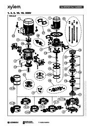
Einbau-, Betriebs- und WartungsanleitungBaureihe <strong>LSB</strong>6.8.3 Längerer StillstandInbetriebnahme ist als Erstinbetriebnahme zuverstehen (siehe Kapitel 6).a) Gefüllte Pumpen Reservepumpen 1x wöchentlich kurz ein- undsofort wieder ausschalten. Eventuell alternativ alsHauptpumpe betreiben. Steht die Reservepumpe unter Druck undTemperatur: alle vorhandenen Sperr- undSpülsysteme eingeschaltet lassen. Nach 5 Jahren Motorlager erneuern.b) Leerstehende Pumpen Mindestens 1x wöchentlich von Hand ausdurchdrehen (nicht einschalten wegenTrockenlauf). Nach 5 Jahren Motorlager erneuern.7. Instandhaltung, Wartung7.1 Allgemeine HinweiseArbeiten an der Pumpe oder Anlage sind nur imStillstand durchzuführen. Beachten Sieunbedingt Kapitel 2.Instandhaltungsarbeiten und Wartung darf nurvon geschultem und erfahrenem Personal, dasmit dem Inhalt dieser Betriebsanleitung vertrautist oder vom Service-Personal des Herstellersdurchgeführt werden.7.2 GleitringdichtungenVor dem Öffnen der Pumpe unbedingt Kapitel 2und Kapitel 8 beachten.Tritt bei der Gleitringdichtung tropfenweiseFördermedium aus, so ist diese beschädigt und mussersetzt werden.Austausch der Gleitringdichtung laut beigelegter"Montageanleitung für Wellenabdichtung".7.3 MotorlagerNach durchschnittlich 5 Jahren ist das Fett in denMotorlagern so gealtert, dass ein Austausch der Lagerempfehlenswert ist. Jedoch sind die Lager nachspätestens 25000 Betriebsstunden zu ersetzen bzw.entsprechend der Wartungsanleitung des Motorlieferanten,wenn dieser eine kürzere Wartungsdauerempfiehlt.7.4 Reinigung der Pumpe Äußerliche Verschmutzung an der Pumpebeeinträchtigt die Wärmeabführung. Daher ist inregelmäßigen Abständen (je nachVerschmutzungsgrad) die Pumpe mit Wasser zureinigen.Die Pumpe darf nicht mit unter Druckstehendem Wasser (z.B. Hochdruckreiniger)gereinigt werden - Wassereintritt in Lager.8. Demontage der Pumpe und Reparatur8.1 Allgemeine HinweiseReparaturen an der Pumpe oder Anlage dürfennur von autorisiertem Fachpersonal oder durchFachpersonal des Herstellers durchgeführtwerden.Bei Ausbau der Pumpe unbedingt Kapitel 2sowie Kapitel 4.1 beachten.Für Montagen und Reparaturen stehen aufAnforderung geschulte Kundendienst-Monteure zurVerfügung.Pumpen, die gesundheitsgefährdende Flüssigkeitenfördern, müssen dekontaminiert werden.Beim Ablassen des Fördermediums ist daraufzu achten, dass keine Gefährdungen fürPersonen und Umwelt entsteht. GesetzlicheBestimmungen sind einzuhalten, ansonstenbesteht Lebensgefahr!Vor Beginn der Demontage muss das Aggregat sogesichert werden, dass es nicht eingeschaltetwerden kann.Das Pumpengehäuse muss drucklos und entleertsein.Alle Absperrorgane in der Saug-, Zulauf- undDruckleitung müssen geschlossen sein. Alle Teile müssen Umgebungstemperaturangenommen haben.Ausgebaute Pumpe, Baugruppen oder Einzelteilegegen Umkippen oder Wegrollen sichern.Offene Flamme (Lötlampe, etc.) beim Zerlegennur dann als Hilfe verwenden, wenn dadurchkeine Brand- oder Explosionsgefahr oder dieGefahr der Entwicklung schädlicher Dämpfeentsteht.Nur Original-Ersatzteile verwenden. Aufrichtigen Werkstoff und passende Ausführungachten.<strong>LSB</strong> 100-<strong>german</strong> Seite 13 Revision 02Artikel Nr. <strong>771076129</strong> Ausgabe 01/2010
Einbau-, Betriebs- und WartungsanleitungBaureihe <strong>LSB</strong>8.2 AllgemeinesArbeiten, die eine Schlagbeanspruchung erfordern,dürfen nur außerhalb der explosiven Atmosphäredurchgeführt werden oder es dürfennur nicht funkenbildende Werkzeuge verwendetwerden.Demontage und Montage grundsätzlich nach derzugehörigen Schnittzeichnung durchführen.Es ist nur handelsübliches Werkzeug erforderlich.Vor dem Zerlegen prüfen, ob die erforderlichenErsatzteile bereit liegen.Die Pumpe immer nur so weit zerlegen, als dies fürden Austausch des zu reparierenden Teils erforderlichist.8.3 Aus- und Einbau der Schutzgitter ausder AntriebslaterneDie Schutzgitter (680) sind in die Fenster derAntriebslaterne (681) geklemmt.Zum Ausbau einen Schraubendreher ca. 4 cm durchdie unterste Lochreihe des Schutzgitters stecken.Dann den Griff des Schraubendrehers soweit nachoben ziehen, bis die Unterkante des Schutzgittersetwas vom Fenster abhebt. Nun kann derSchraubendreher samt Schutzgitter aus dem Fensterherausgezogen werden (siehe Bild 8).8.4 Ausbau der LaufeinheitUnter Laufeinheit versteht man alle Pumpenteile mitAusnahme des Spiralgehäuses (102V). Da diePumpen in Blockbauweise konstruiert sind, kann dasSpiralgehäuse (102V) auf dem Fundament und in derRohrleitung verbleiben, sofern nicht dasSpiralgehäuse selbst repariert werden soll. Spiralgehäuse (102V) über Entleerungsstopfen(912.11) entleeren. Verschraubung etwaiger Sperr- oderSpülwasserleitungen lösen. Stützfuß (183) Verschraubung am Fundamentlösen (nicht bei allen Baugrößen vorhanden). Laufeinheit an Hebezeug hängen, so dass beimAusbau die Laufeinheit weder nach unten sackt,noch nach oben im Spiralgehäuse drückt.Befestigungsbeispiel siehe Bild 9.Bild 9 Gehäuseverschraubung (Kopfschrauben 901.11)komplett abschrauben. Laufeinheit axial aus dem Spiralgehäuse ziehen.Dabei können die Abdrückschrauben (901.42)verwendet werden.8.5 Ausbau des LaufradesBild 8Beim Einbau zuerst Schraubendreher ca. 4 cm durchdie unterste Lochreihe des Schutzgitters stecken.Dann den oberen Teil des Schutzgitters in den oberenRand der Fensteröffnung stecken. Nun den Griff desSchraubendrehers so weit nach oben ziehen, bis dieDurchbiegung des Schutzgitters ausreicht, um diesesbis zum Anschlag in das Fenster der Antriebslaternehinein zu schieben.Schraubendreher nur so weit anheben, als zumEinschieben des Schutzgitters in das Fensterunbedingt notwendig ist. Wenn das Schutzgitternach dem Einbau zu wenig im Fenster klemmt:Schutzgitter noch einmal ausbauen, etwasflacher drücken und wieder einbauen.Beigelegte "Montageanleitung zu Wellenabdichtung"beachten. Hat das Laufrad Rückenschaufeln, sokontrollieren Sie vor dem weiteren Zerlegen dieaxiale Spaltweite "a" zwischen Laufrad (230) undGehäusedeckel (161). Beurteilung dergemessenen Spaltweite siehe Kapitel 8.8.1.Laufradmutter (922) durch kurzen gefühlvollenSchlag auf den Schraubenschlüssel lösen(Rechtsgewinde). Eventuell mit einem Dorn in derQuerbohrung der Steckwelle (im Klemmbereich)gegenhalten. Laufrad (230) abziehen mit Hilfe zweierSchraubendreher oder Montiereisen (Bild 10).Passfeder (940.31) herausnehmen.Schraubendreher oder Montiereisen nur imBereich von Laufradschaufeln ansetzen, damitdie Strömungskanäle nicht deformiert werden.<strong>LSB</strong> 100-<strong>german</strong> Seite 14 Revision 02Artikel Nr. <strong>771076129</strong> Ausgabe 01/2010
Einbau-, Betriebs- und WartungsanleitungBaureihe <strong>LSB</strong>Ein weiteres Zerlegen sowie der Zusammenbauder Laufeinheit erfolgt leichter in vertikalerAufstellung. Kippgefahr beachten!Ablagerungen am Laufrad (230), im Spiralgehäuse(102V) oder am Gehäusedeckel (161) sind zuentfernen.8.8.1 Dichtspalte beim LaufradSaugseite des Laufrades Rückenschaufeln desLaufradesAntriebseite des LaufradesNur bei Pumpengröße100-65-315125-80-315125-100-315150-125-315Bild 108.6 Ausbau der Wellenabdichtung Vor der Demontage des Gehäusedeckels"Montageanleitung zu Wellenabdichtung"beachten. Sechskantmutter (902.32) lösen (nicht bei allenPumpengrößen vorhanden) und Gehäusedeckel(161) aus Lagerträgerlaterne (344) nehmen.8.7 Ausbau der SteckwelleVerschraubung (920.41) lösen und Motor samtSteckwelle (210) aus der Antriebslaterne (341)herausziehen.Radiale Steckwellenverschraubung (904.41 und904.42) lösen (Gewindestifte) und Steckwelle(210) von der Motorwelle abziehen. Eventuell zurUnterstützung (losbrechen) einen kräftigenSchraubendreher in die Querbohrung derSteckwelle einführen, damit gegen die Stirnflächeder Motorwelle drücken und so die beiden Wellengegeneinander verschieben.8.8 InstandsetzungNach dem Zerlegen sind alle Teile sorgfältig zureinigen und auf Verschleiß zu prüfen. Abgenützteoder beschädigte Teile sind gegen Neuteile(Ersatzteile) auszutauschen.Es sind grundsätzlich neue Dichtelemente zuverwenden.Alle PTFE-Dichtelemente und Graphitdichtungensind nur zur einmaligen Verwendunggeeignet.In den meisten Fällen ist es zweckmäßig, fallsbeschädigt absolut notwendig, die Wellenabdichtungzu erneuern.Nenndurchmesser D (mm)606885100120135155175220min. 0,15 0,17 0,20 0,22 0,25Radialer Spalt neumax. 0,19 0,22 0,24 0,27 0,30s (mm)abgenützt 0,78 0,85 0,90 1,05 1,15Axialer Spalt neu 0,8 - 1,2a (mm) abgenützt max. 1,7Sind die Werte für "abgenützt" erreicht oderüberschritten, müssen die betroffenen Teileersetzt werden.Bei Spiralgehäusen (102V) mit Spaltring (502.11) bzw.bei Gehäusedeckeln (161) mit Spaltring (502.31) gibtes zur Wiederherstellung des korrekten Spaltesfolgende Möglichkeiten:a) Laufrad (230) und Spaltring erneuern. Damit sinddie Originalmaße wiederhergestellt.b) Spaltringe mit entsprechendem Innendurchmesseranfertigen und so wieder die Original-Spaltweiteerreichen. Bitte nehmen Sie Kontakt mit demHersteller auf.Bei Spiralgehäusen (102V) bzw. Gehäusedeckeln(161) ohne Spaltring kann im Reparaturfall auchnachträglich ein Spaltring eingesetzt werden. Dazu istaber eine Nacharbeit (Nachdrehen) im Spiralgehäusebzw. im Gehäusedeckel erforderlich. Bitte nehmen SieKontakt mit dem Hersteller auf.8.9 Montage8.9.1 AllgemeinesDie Montage wird in umgekehrter Reihenfolgevorgenommen wie die Demontage, wobei zusätzlichfolgendes zu beachten ist: Auf größte Reinlichkeit ist bei der Montage zuachten.<strong>LSB</strong> 100-<strong>german</strong> Seite 15 Revision 02Artikel Nr. <strong>771076129</strong> Ausgabe 01/2010
Einbau-, Betriebs- und WartungsanleitungBaureihe <strong>LSB</strong>Enge Schiebesitze, z.B. zwischen Steckwelle(210) und Motorwelle oder Laufrad (230) undWelle (210) sowie Gewinde eventuell mitgeeignetem Gleitmittel (z.B. Molykote / Never-Seeze) bestreichen, damit die Montage und auchdie nächste Demontage erleichtert wird.Gleitmittel jedoch nur dann verwenden, wennsichergestellt ist, dass es zwischenFördermedium und Gleitmittel zu keinengefährlichen Reaktionen kommen kann.Schrauben sind mit folgenden Drehmomentenanzuziehen:VerschraubungGehäuseschraubenAlle übrigen SchraubenAnziehdrehmoment in NmGröße Geschmiertes TrockenesGewinde GewindeM12 35 50M16 105 150M20 210 305M10 35 50M12 60 90M16 150 220 Keine übertriebene Gewalt anwenden. Montage der Steckwelle siehe Kapitel 8.9.2. Montage der Gleitringdichtung siehe separateBeschreibung "Montageanleitung derWellenabdichtung" und Kapitel 8.5. Bei Laufrädern mit Rückenschaufeln nach derMontage des Laufrades (230) und nachFestziehen der Laufradmutter (922) korrektenAxialspalt zwischen Rückenschaufeln undGehäusedeckel (161) kontrollieren. Siehe Kapitel8.8.1. Nach dem Zusammenbau der Laufeinheit undauch nach dem Einbau in das SpiralgehäuseWelle drehen und damit Leichtgängigkeit derPumpe kontrollieren. Die Wellenabdichtungenverursachen etwas Drehwiderstand, es darf aberkeine Berührung zwischen Metallteilen bemerkbarsein.Vor Inbetriebnahme unbedingt wieder alleHilfsleitungen und Sicherheitseinrichtungenmontieren bzw. anschließen und in Betriebsetzen.8.9.2 Montage der Steckwelle Paßfeder in den Motorstummel einlegen. Motorwellenstummel mit Gleitmittel bestreichen(siehe Punkt 8.9.1.). Steckwelle so weit auf die Motorwelleaufschieben, bis das Maß A erreicht ist (siehe Bild11 und Tabelle). Motorwelle durch die radialen Steckwellenbohrungenca. 2-3 mm tief mit einem Spiralbohrermit 90° Spitze ansenken (siehe Bild 11).Späne aus dem Gewindeloch entfernen (z.B. mitDruckluft), Gewindestifte (904.41 und 904.42)einschrauben und sichern (z.B. mit Omnifit 100 Moder Loctite).Korrekten Rundlauf der Steckwelle gegenüberdem Motorflansch mittels Meßuhr kontrollieren(siehe Bild 11.). Der Zeigerausschlag der Meßuhrdarf max. 0,1 mm betragen.Bild 11TypeMaß A bei Motor-Baugröße80 90 100 112 132 160 180 20040-25-160 157 157 197 197 197 232 - -40-25-200 157 157 197 197 197 232 - -40-25-250 162 162 202 202 202 237 237 23750-32-160 157 157 197 197 197 232 - -50-32-200 157 157 197 197 197 232 - -50-32-250 162 162 202 202 202 237 237 23750-32-315 - - 202 202 197 237 237 23765-40-160 157 157 197 197 197 232 - -65-40-200 157 157 197 197 197 232 232 -65-40-250 162 162 202 202 202 237 237 23765-40-315 - - 202 202 197 237 237 23780-50-160 157 157 197 197 197 232 232 -80-50-200 157 157 197 197 202 232 232 23280-50-250 - 162 202 202 202 237 237 23780-50-315 - - 202 202 202 237 237 237100-65-160 162 162 202 202 202 237 237 237100-65-200 - 162 202 202 202 237 237 237100-65-250 - 162 202 202 206 237 237 237100-65-315 - - 206 206 202 241 241 241125-80-160 - 162 202 202 202 237 237 237125-80-200 - 162 202 202 202 237 237 237125-80-250 - - 202 202 202 237 237 237125-80-315 - - - 206 206 241 241 241125-100-200 - - 202 202 202 237 237 237125-100-250 - - 216 216 216 251 251 251125-100-315 - - - - 206 241 241 241150-125-250 - - - - 216 251 251 251150-125-315 - - - - - 241 241 241200-150-250 - - - - - 251 251 2519. Ersatzteilempfehlung, Reservepumpen9.1 ErsatzteileDie Ersatzteile sind für die Bedingungen eineszweijährigen Dauerbetriebes auszuwählen. Falls keineanderen Richtlinien zu beachten sind, werden die inunten angeführter Liste angegebenen Stückzahlen fürErsatzteile empfohlen (nach DIN 24296).<strong>LSB</strong> 100-<strong>german</strong> Seite 16 Revision 02Artikel Nr. <strong>771076129</strong> Ausgabe 01/2010
Einbau-, Betriebs- und WartungsanleitungBaureihe <strong>LSB</strong>Zur Sicherung einer optimalen Verfügbarkeitempfehlen wir, insbesondere bei Ausführungenaus Sonderwerkstoffen und Gleitringdichtung,auf Grund der längeren Beschaffungszeitenentsprechende Ersatzteile zu bevorraten.Anzahl der Pumpen(einschließlich Reservepumpen)2 3 4 5 6/7 8/9 10/+ErsatzteileStückzahl der ErsatzteileLaufrad 1 1 1 2 2 2 20%Spaltring 2 2 2 3 3 4 50%Welle mit Passfedernund Muttern1 1 1 2 2 2 20%Dichtungen fürPumpengehäuse Sätze4 6 8 8 9 12 150%sonstige Dichtungen 4 6 8 8 9 10 100%SätzeGleitringdichtung Satz 1 1 2 2 2 3 25%ErsatzteilbestellungBei Ersatzteilbestellung bitten wir Sie um folgendeAngaben:Type: ______________________________________________________________________S/N (Auftrags Nr.) ___________________________________________________Teilebezeichnungen _______________________________________________Schnittzeichnung ____________________________________________________Alle Angaben finden Sie auf dem Datenblatt und / oderder Auftragsbestätigung und der dazugehörigenSchnittzeichnung.Ersatzteile in trockenen Räumen und vorSchmutz geschützt aufbewahren!9.2 ReservepumpenFür Pumpen in Anlagen, deren AusfallMenschenleben gefährden bzw. hoheSachschäden oder Kosten verursachen können,ist unbedingt eine ausreichende Anzahl vonReservepumpen in der Anlage betriebsbereit zuhalten. Die Betriebs-bereitschaft ist durchlaufende Kontrolle sicherzustellen, siehe Kapitel6.8.Reservepumpen entsprechend Kapitel 6.8aufbewahren!<strong>LSB</strong> 100-<strong>german</strong> Seite 17 Revision 02Artikel Nr. <strong>771076129</strong> Ausgabe 01/2010
Einbau-, Betriebs- und WartungsanleitungBaureihe <strong>LSB</strong>10. Störungen - Ursachen und BehebungDie angeführten Hinweise auf Ursachen undBehebung von Störungen sollen zur Erkennung desProblems dienen. Für Störungen, die der Betreibernicht selbst beseitigen kann oder will, steht derKundendienst des Herstellers zur Verfügung. BeiReparaturen und Änderungen an der Pumpe durchden Betreiber sind besonders die Auslegungsdatenauf dem Datenblatt und / oder der Auftragsbestätigungsowie Kapitel 2 dieser Betriebsanleitung zu beachten.Gegebenenfalls ist das schriftliche Einverständnis desHerstellers einzuholen.Förderstrom zu geringFörderstrom hört nach einiger Zeit aufFörderhöhe zu geringFörderhöhe zu hochAntriebsmaschine überlastetUnruhiger Lauf der PumpeZu hohe Temperatur in der PumpeZu hohe Temperatur an derWellendichtungZu hohe Temperatur an der LagerungUndichtheit an der PumpeZu starke Leckage der WellendichtungUrsacheBehebung■ Gegendruck zu hoch Anlage auf Verunreinigungen überprüfen, Schieber geöffnetWiderstände in der Druckleitung vermindern (Filter reinigen, ...)größeres Laufrad verwenden (Antriebsleistung beachten)■ ■ ■ Gegendruck zu gering, Förderstrom zu groß druckseitigen Schieber drosseln■ ■ Drehzahl zu hoch Drehzahl verringernDrehzahl der Antriebsmaschine mit vorgeschriebenerPumpendrehzahl (Leistungsschild) vergleichenBei Drehzahlregelung (Frequenzumformer) Sollwert-Einstellung kontrollieren■ ■ Drehzahl zu klein Drehzahl erhöhen (verfügbare Antriebsleistung beachten)Drehzahl der Antriebsmaschine mit vorgeschriebenerPumpendrehzahl (Leistungsschild) vergleichenBei Drehzahlregelung (Frequenzumformer) Sollwert-Einstellung kontrollieren■ ■ ■ ■ Förderstrom zu klein Mindestfördermenge vergrößern (Schieber öffnen, Bypass)■ Förderstrom zu groß Fördermenge verringern (Schieber drosseln)■ ■ Laufraddurchmesser zu groß kleineres Laufrad verwenden■ ■ Laufraddurchmesser zu klein größeres Laufrad verwenden (verfügbare Antriebsleistungbeachten)■ ■ ■ ■ Pumpe und / oder Rohrleitung nicht völlig mit Flüssigkeit füllengefülltentlüften■ ■ ■ Pumpe oder Saug- / Zulaufleitung verstopft reinigen■ ■ Luftsack in Rohrleitung entlüftenLeitungsführung verbessern■ ■ ■ ■ ■ Saughöhe zu groß / NPSH der Anlage zu klein Flüssigkeitsspiegel erhöhenVordruck erhöhenWiderstände der Zulauf- / Saugleitung verringern (Verlauf undNennweite ändern, Absperrorgane öffnen, Siebe reinigen)■ ■ ■ Luft wird angesaugt Flüssigkeitsspiegel erhöhenVakuumdichtheit der Saugleitung prüfen und herstellen■ ■ ■ Ansaugen von Luft durch die Wellenabdichtung Sperrleitung reinigenSperrdruck erhöhenWellenabdichtung erneuern■ ■ Drehrichtung falsch Zwei Phasen der Stromzuführung vertauschen (vomElektrofachmann durchzuführen)■ ■ ■ ■ Verschleiß der Innenteile abgenützte Teile erneuern■ ■ ■ Dichte und / oder Viskosität des Fördermediums zu hoch Rückfrage erforderlich■ ■ Riefen und Rauigkeit an Welle Teil erneuern■ ■ Ablagerungen an Gleitringdichtung reinigengegebenenfalls Gleitringdichtung erneuerneventuell Fremdspülung oder Quench vorsehen■ ■ Unwucht des Laufrades Verstopfungen / Ablagerungen beseitigenev. Laufrad erneuern; Welle auf Rundlauf prüfen■ ■ ■ ■ ■ Rohrleitungskräfte zu hoch (Aggregat verspannt) ändern (Rohrleitungen abfangen, Kompensatoren, etc.)Fundamentplatte / Rahmen korrekt montiert / vergossen?■ Elektrische Anspeisung nicht korrekt (2-Phasenlauf) Spannung aller Phasen kontrollierenKabelanschlüsse bzw. Sicherungen prüfen■ Dichtung unzureichend Schrauben nachziehenDichtung erneuern■ ■ Lager schadhaft erneuern■ Entlastungseinrichtung ungenügend Entlastungsbohrungen im Laufrad reinigenabgenützte Teile ersetzen (Laufrad, Spaltringe)an den bei Bestellung angegebenen Systemdruck /Zulaufdruck angleichen■ Anlagenbedingte Schwingungen Rückfrage erforderlich<strong>LSB</strong> 100-<strong>german</strong> Seite 18 Revision 02Artikel Nr. <strong>771076129</strong> Ausgabe 01/2010
Einbau-, Betriebs- und WartungsanleitungBaureihe <strong>LSB</strong>11. MotorbetriebsanleitungDie nachstehenden Anweisungen sind genau zubefolgen, um die Sicherheit bei der Installation,beim Betrieb und bei der Wartung des Motorszu gewährleisten. Alle Personen, die mit diesenAufgaben befaßt sind, sind auf die vorliegendeAnleitung hinzuweisen. Die Nichtbefolgung derhierin enthaltenen Anweisungen kann denVerlust der Gewährleistung zur Folge haben.StromanschlussVergewissern Sie sich, dass die auf demLeistungsschild angegebene Spannung denWerten Ihres Speisenetzes entspricht.Die Erdung vor allen anderen Anschlüssenvornehmen.Es empfiehlt sich der Einbau eineshochsensiblen Fehlerstrom-Schutzschalters (30mA) als zusätzlicher Schutz gegenlebensgefährliche Stromstöße im Falle einerfehlerhaften Erdung.Den Netzanschluss mit einem allpoligen Schalter odereiner anderen Vorrichtung, die die allpoligeNetzausschaltung sichert (also alle Speiseleitungenunterbricht) und einen Abstand der Öffnungskontaktevon mindestens 3 mm aufweist, vornehmen.Die Abdeckung des Klemmenbretts abnehmen, indemman die Befestigungsschrauben aufschraubt. DieVerbindungen wie auf der Rückseite derKlemmenbrettabdeckung angegeben bzw. inAbbildung 3 - 4.Die Wechselstromausführung hat einen eingebautenÜberlastschutz, während die Drehstromausführungkundenseitig gesichert werden muss. Verwenden Siedazu einen magnetothermischen Motorschutzschalteroder einen Anlasser komplett mit Fernschalter,Thermorelais und vorgelagerter Schmelzsicherung.Das Überstromrelais ist auf dem Nennstrom desMotors entsprechend dem Leistungsschildeinzustellen.Das Thermorelais kann auf einen leicht niedrigerenWert als den der Volllast eingestellt werden, wenn dieMotorpumpe sicher nicht voll ausgelastet wird;hingegen darf der Thermoschutz nicht auf einenhöheren Wert als den Nennstrom eingestellt werden.StörungssucheStörung Mögliche Ursache Abhilfe1. Die Pumpe startetnicht2. Überlastschutzspricht an:- zufälligA) Spannungsabfallim NetzB) SicherungendurchgebranntB1 UngeeigneteSicherungen(Ansprechstrom zuniedrig)B2 Motor oderSpeisekabelbeschädigtC) Überlastschutz hateingegriffenA) MomentanerAusfall einer Phase- systematisch C) FalscheEinstellung desMotorschutzschaltersD) Zu hoheFördermengeE) Die Dichte oderViskosität derFlüssigkeitübersteigen dieGrenzwerteA) StromversorgungsicherstellenB1 GeeigneteSicherungeneinbauenB2 Motor reparierenoder KabelaustauschenC) Überlastschutzrückstellen (beierneutem Ausfallsiehe Punkt 2)C) Auf denNennstrom desLeistungsschildeseinstellenD) Druckventilschließen, bis dieFördermenge demArbeitsbereich derPumpe entsprichtE) EffektiverforderlicheMotorleistungbestimmen und MotorentsprechendersetzenKontrolle der Drehrichtung bei Elektropumpen mitDrehstrommotorenDie Kontrolle der Drehrichtung kann vor dem Anfüllender Pumpe mit der zu pumpenden Flüssigkeiterfolgen, vorausgesetzt, dass man die Pumpe nurkurz drehen lässt.Der Betrieb der Pumpe vor dem Anfüllen mitder Flüssigkeit ist nicht zulässig.Kontinuierlicher Trockenlauf beschädigt dieGleitringdichtung.Ist die Drehrichtung nicht entgegen dem Uhrzeigersinn(von der Seite des Saugstutzens gesehen), so sindzwei Speisedrähte umzustecken.<strong>LSB</strong> 100-<strong>german</strong> Seite 19 Revision 02Artikel Nr. <strong>771076129</strong> Ausgabe 01/2010
Einbau-, Betriebs- und WartungsanleitungBaureihe <strong>LSB</strong><strong>LSB</strong> 100-<strong>german</strong> Seite 20 Revision 02Artikel Nr. <strong>771076129</strong> Ausgabe 01/2010
Einbau-, Betriebs- und WartungsanleitungBaureihe <strong>LSB</strong>Montageanleitung Einzel-Gleitringdichtung ohne Wellenschutzhülse (AusführungscodeS1..2)1. SicherheitshinweiseJede Person, die mit dem Ein- und Ausbau, derBedienung, Inbetriebnahme und Instandhaltungder Wellenabdichtung beschäftigt ist, mussneben dieser Montageanleitung auch dieEinbau-, Betriebs- und Wartungsanleitung derjeweiligen Pumpe und besonders Kapitel 8.1"Allgemeine Hinweise" und Kapitel 8.2"Allgemeines" gelesen und verstanden habenund diese unbedingt beachten!Für Pumpen die komform der Richtlinie 94/9/EG(Atex95) für explosionsgefährdete Umgebungausgeführt sind, ist unbedingt dieZusatzbetriebsanleitung zum Explosionsschutzder Gleitringdichtung zu beachten.Die folgenden Angaben sind, so weit sie den innerenAufbau der Gleitringdichtung betreffen, nur allgemeingültig. Etwaige Besonderheiten entnehmen Sie demTypenblatt der Gleitringdichtung oder der Anleitungdes Gleitringdichtungherstellers.2. AusführungsbeschreibungDiese Wellenabdichtung ist eine Einzel-Gleitringdichtung mit Einbaumaßen nach EN 12756(DIN 24960) Ausführung "K". API Plan 02 / ISO Plan00.Durch den patentierten Zyklon-Dichtungsraum istkeine zusätzliche Spülung des Gleitringdichtungsraumeserforderlich.Angaben über Werkstoffe und Einsatzbereich derverwendeten Gleitringdichtungen entnehmen Sie demDatenblatt in der Betriebsanleitung bzw. derAuftragsbestätigung.Teilbezeichnungen:161 Gehäusedeckel210 Welle230 Laufrad412.21 O-Ring433 Gleitringdichtung502.31*) Spaltring524 Wellenschutzhülse527 a) Stellring560 b) Stift904.31 a) Gewindestift904.32*) Gewindestift922 Laufradmutter940.31 Passfeder*) optionala) nicht bei allen Gleitringdichtungs-Bauartenb) nur bei Gleitringdichtungen mit PTFE-O-RingenTechnische Änderungen vorbehalten!Nenngrößeder Glrd.∅d 1 ∅d 7 l 1K A B ∅d L33 33 48 42,5 7,5 50 1943 43 61 45 7,5 52,5 2853 53 73 47,5 10 57,5 38<strong>LSB</strong> 100-<strong>german</strong> Seite 21 Revision 02Artikel Nr. <strong>771076129</strong> Ausgabe 01/2010
Einbau-, Betriebs- und WartungsanleitungBaureihe <strong>LSB</strong>3. Ausbau der GleitringdichtungVerwenden Sie dazu die zugehörige Schnittzeichnungund das beiliegende Typenblatt derGleitringdichtung. Ausbau und Zerlegen der Pumpe entsprechendder Einbau-, Betriebs- und Wartungsanleitung bisinklusive Kapitel 8.6. Stellring (527) (sofern vorhanden) und rotierendenTeil der Gleitringdichtung (433) von der Welle(210) abziehen. Dem beiliegenden Typenblatt derGleitringdichtung ist zu entnehmen, ob vorherKlemmschrauben an der Gleitringdichtung zulösen sind. Stationären Teil der Gleitringdichtung (433) ausdem Gehäusedeckel (161) ziehen. Aufnahmebohrung (∅d 7 ) im Gehäusedeckel (161)und die Oberfläche der Welle (210) reinigen.Die Wiederverwendung von Gleitringdichtungen,die bereits längere Zeit im Einsatzwaren, birgt die Gefahr von Undichtheiten ander Gleitfläche nach dem Wiedereinbau. Eswird daher der Ersatz der Gleitringdichtungdurch eine neue empfohlen. Die ausgebauteGleitringdichtung kann vom Hersteller überholtwerden und als Ersatz-Gleitringdichtung dienen.4. Einbau der GleitringdichtungVerwenden Sie dazu die zugehörige Schnittzeichnungund das beiliegende Typenblatt derGleitringdichtung.Es dürfen nur Gleitringdichtungen eingebautwerden, bei denen eine schriftlicheBescheinigung der Konformität gemäß derRichtlinie 94/9/EG vorliegt.Bei Änderung der Gleitringdichtungstypebzw.des Gleitringdichtungsherstellers müssendie Angaben der maximalen Betriebstemperaturdes Fördermediums und derTemperaturklasse erneut überprüft werden.Auf größte Sauberkeit achten! Besonders dieGleitflächen müssen sauber, trocken undunbeschädigt bleiben. Auch keine SchmieroderGleitmittel auf die Gleitflächen derGleitringdichtung auftragen.Falls bei der Ersatzgleitringdichtung Gleitmittelbeigepackt ist, dann dieses verwenden.Mineralische Fette oder Öle nur dannverwenden, wenn völlig sicher ist, dass dieElastomere der Gleitringdichtung ölbeständigsind. Kein Silicon verwenden.Nur Gleitmittel verwenden, von denensichergestellt ist, dass es zwischen ihnen unddem Fördermedium zu keiner gefährlichenReaktion kommen kann.Stellen Sie alle erforderlichen Teile bereit, damitdie Montage zügig vor sich geht. Die Gleitmittelwirken nur kurze Zeit, so dass danach dieVerschiebbarkeit und damit die automatischeEinstellung der Elastomere verloren geht.Schieben Sie die Elastomere nie über scharfeKanten. Falls erforderlich Montagehülsenverwenden.Stationären Teil der Gleitringdichtung gleichmäßigin den Gehäusedeckel (161) drücken. Dazueventuell einen Stempel mit weicher Oberflächeverwenden. Ungleiche Belastung bedeutetBruchgefahr für die Gleitfläche.Gleitfläche nicht beschädigen!Auf satte axiale Anlage der stationären Einheit imGehäusedeckel achten. Die Gleitfläche mussgenau senkrecht zur Welle stehen.Falls ein Fixierstift (560) vorhanden ist, daraufachten, dass dieser in die Nut derGleitringdichtung eingreift, ohne dass er dieGleitringdichtung berührt.Rotierende Einheit der Gleitringdichtung auf dieWelle (210) aufschieben.Laufradseitige Anlagefläche der Gleitringdichtunggenau mit Wellenbund abschließen lassen (Maßl 1K ). Für Gleitringdichtungen ohne eigeneKlemmschrauben dient der Stellring (527) alsAnschlag.Gleitringdichtungen mit Faltenbälgen beiMontage so schieben, dass der Balgzusammengedrückt und nicht gestreckt wird(Reißgefahr!).Weiterer Zusammenbau und Einbau der Pumpeentsprechend Kapitel 8 der Einbau-, Betriebs- undWartungsanleitung.<strong>LSB</strong> 100-<strong>german</strong> Seite 22 Revision 02Artikel Nr. <strong>771076129</strong> Ausgabe 01/2010
Einbau-, Betriebs- und WartungsanleitungBaureihe <strong>LSB</strong>Montageanleitung Einzel-Gleitringdichtung mit Quench ohne Wellenschutzhülse(Ausführungscode S4..2)1. SicherheitshinweiseJede Person, die mit dem Ein- und Ausbau, derBedienung, Inbetriebnahme und Instandhaltungder Wellenabdichtung beschäftigt ist, mussneben dieser Montageanleitung auch dieEinbau-, Betriebs- und Wartungsanleitung derjeweiligen Pumpe und besonders Kapitel 8.1"Allgemeine Hinweise" und Kapitel 8.2"Allgemeines" gelesen und verstanden habenund diese unbedingt beachten!Für Pumpen die komform der Richtlinie 94/9/EG(Atex95) für explosionsgefährdete Umgebungausgeführt sind, ist unbedingt dieZusatzbetriebsanleitung zum Explosionsschutzder Gleitringdichtung zu beachten.Die folgenden Angaben sind, so weit sie den innerenAufbau der Gleitringdichtung betreffen, nur allgemeingültig. Etwaige Besonderheiten entnehmen Sie demTypenblatt der Gleitringdichtung oder der Anleitungdes Gleitringdichtungsherstellers.2. AusführungsbeschreibungDiese Wellenabdichtung ist eine Einzel-Gleitringdichtung mit Einbaumaßen nach EN 12756(DIN 24960) Ausführung "K", Form "U". API Plan 62 /ISO Plan 09. Die Beständigkeit der Werkstoffe imGleitringdichtungsraum (speziell die der Elastomere)gegenüber der Quenchflüssigkeit ist zu beachten.Der Quenchraum muß drucklos von Quenchflüssigkeitdurchströmt werden. Anschluß siehefolgende Schnittzeichnung.Die Quenchflüssigkeit muß so ausgewähltwerden, daß es zwischen ihr und demFördermedium zu keinen gefährlichenReaktionen kommen kann. Die Quenchflüssigkeitkann durch das Fördermediumkontaminiert werden, daher ist durch denBetreiber gegebenenfalls auf eine entsprechendeEntsorgung zu achten.Durch den patentierten Zyklon-Dichtungsraum istkeine zusätzliche Spülung des Gleitringdichtungsraumeserforderlich.Angaben über Werkstoffe und Einsatzbereich derverwendeten Gleitringdichtungen entnehmen Sie demDatenblatt in der Betriebsanleitung bzw. derAuftragsbestätigung.QI ... Quench Eintritt (471Q)Q0 ... Quench Austritt (471Q)<strong>LSB</strong> 100-<strong>german</strong> Seite 23 Revision 02Artikel Nr. <strong>771076129</strong> Ausgabe 01/2010
Einbau-, Betriebs- und WartungsanleitungBaureihe <strong>LSB</strong>Teilbezeichnungen:161 Gehäusedeckel210 Welle230 Laufrad412.21 O-Ring412.32 O-Ring433 Gleitringdichtung471Q Quenchdeckel502.31*) Spaltring527 a) Stellring542.31 Drosselbuchse560 b) Stift904.31 a) Gewindestift904.32*) Gewindestift923 Laufradmutter940.31 Passfeder*) optionala) nicht bei allen Gleitringdichtungs-Bauartenb) nur bei Gleitringdichtungen mit PTFE-O-RingenTechnische Änderungen vorbehalten!Nenngrößeder Glrd.∅d 1 ∅d 7 l 1K A B ∅d L QI, Q033 33 48 42,5 7,5 50 1943 43 61 45 7,5 52,5 2853 53 73 47,5 10 57,5 381/4-18NPT3/8-18NPT3/8-18NPT3. Ausbau der GleitringdichtungVerwenden Sie dazu die zugehörige Schnittzeichnungund das beiliegende Typenblatt derGleitringdichtung. Ausbau und Zerlegen der Pumpe entsprechendder Einbau-, Betriebs- und Wartungsanleitung bisinklusive Kapitel 8.6.Stellring (527) (sofern vorhanden) und denrotierenden Teil der Gleitringdichtung (433) vonder Welle (210) abziehen. Dem beiliegenden Typenblatt der Gleitringdichtungist zu entnehmen, ob vorherKlemmschrauben an der Gleitringdichtung zulösen sind.Gehäusedeckel (161) samt Quenchdeckel (471Q)ausbauen. Sechskantschrauben (901.42) alsAbdrückhilfe verwenden..Stationären Teil der Gleitringdichtung (433) unddie Drosselbuchse (542.31) aus demQuenchdeckel (471Q) herausziehen.Aufnahmebohrung (∅d 7 ) im Quenchdeckel (471Q)und die Oberfläche der Welle (210) reinigen.Die Wiederverwendung von Gleitringdichtungen,die bereits längere Zeit im Einsatzwaren, birgt die Gefahr von Undichtheiten ander Gleitfläche nach dem Wiedereinbau. Eswird daher der Ersatz der Gleitringdichtungdurch eine neue empfohlen. Die ausgebauteGleitringdichtung kann vom Hersteller überholtwerden und als Ersatz-Gleitringdichtung dienen.4. Einbau der GleitringdichtungVerwenden Sie dazu die zugehörige Schnittzeichnungund das beiliegende Typenblatt derGleitringdichtung.Es dürfen nur Gleitringdichtungen eingebautwerden, bei denen eine schriftlicheBescheinigung der Konformität gemäß derRichtlinie 94/9/EG vorliegt.Bei Änderung der Gleitringdichtungstypebzw.des Gleitringdichtungsherstellers müssendie Angaben der maximalen Betriebstemperaturdes Fördermediums und derTemperaturklasse erneut überprüft werden.Auf größte Sauberkeit achten! Besonders dieGleitflächen müssen sauber, trocken undunbeschädigt bleiben. Auch keine SchmieroderGleitmittel auf die Gleitflächen derGleitringdichtung auftragen.Falls bei der Ersatzgleitringdichtung Gleitmittelbeigepackt ist, dann dieses verwenden.Mineralische Fette oder Öle nur dannverwenden, wenn völlig sicher ist, dass dieElastomere der Gleitringdichtung ölbeständigsind. Kein Silicon verwenden.Nur Gleitmittel verwenden, von denensichergestellt ist, dass es zwischen ihnen unddem Fördermedium zu keiner gefährlichenReaktion kommen kann.Stellen Sie alle erforderlichen Teile bereit, damitdie Montage zügig vor sich geht. Die Gleitmittelwirken nur kurze Zeit, so dass danach dieVerschiebbarkeit und damit die automatischeEinstellung der Elastomere verloren geht.Schieben Sie die Elastomere nie über scharfeKanten. Falls erforderlich Montagehülsenverwenden.Drosselbuchse (542.31) in den Quenchdeckel(471Q) vorsichtig hineindrücken.Stationären Teil der Gleitringdichtung gleichmäßigin den Quenchdeckel (471Q) drücken. Dazueventuell einen Stempel mit weicher Oberfläche<strong>LSB</strong> 100-<strong>german</strong> Seite 24 Revision 02Artikel Nr. <strong>771076129</strong> Ausgabe 01/2010
Einbau-, Betriebs- und WartungsanleitungBaureihe <strong>LSB</strong>verwenden. Ungleiche Belastung bedeutetBruchgefahr für die Gleitfläche.Gleitfläche nicht beschädigen!Auf satte axiale Anlage der stationären Einheit imQuenchdeckel achten. Die Gleitfläche mussgenau senkrecht zur Welle stehen.Falls ein Fixierstift (560) vorhanden ist, daraufachten, dass dieser in die Nut derGleitringdichtung eingreift, ohne dass er dieGleitringdichtung berührt.Gehäusedeckel (161) vorsichtig einsetzen, bis eraxial in der Lagerträgerlaterne (344) anliegt.Rotierende Einheit der Gleitringdichtung auf dieWelle (210) aufschieben.Laufradseitige Anlagefläche der Gleitringdichtunggenau auf Maß A einstellen. Für Gleitringdichtungohne eigene Klemmschrauben dient der Stellring(527) als Anschlag.Gleitringdichtungen mit Faltenbälgen beiMontage so schieben, dass der Balgzusammengedrückt und nicht gestreckt wird(Reißgefahr!).Gleitmittel (Molykote, etc.) zwischen Wellenschutzhülseund Welle nur dann verwenden,wenn sichergestellt ist, dass es zwischenFördermedium und Gleitmittel zu keinengefährlichen Reaktionen kommen kann.Weiterer Zusammenbau und Einbau der Pumpeentsprechend Kapitel 8 der Einbau-, Betriebs- undWartungsanleitung.Vor dem Einschalten der Pumpe unbedingt dasSpülsystem für den Quench wieder anschließenund in Betrieb nehmen.<strong>LSB</strong> 100-<strong>german</strong> Seite 25 Revision 02Artikel Nr. <strong>771076129</strong> Ausgabe 01/2010
Einbau-, Betriebs- und WartungsanleitungBaureihe <strong>LSB</strong>Ausführung: S1...2 Einzel-GLRD, nicht entlastet (DIN 24960, l 1k / EN 12756, Ausf. K, Form U), Laufrad mitRückenschaufelnDie Wellenabdichtung Ihrer Pumpe finden Sie auf dem Datenblatt / der Auftragsbestätigung. Siehe auch Kapitel3.1.1 Bezeichnungsschema.Nr.102 V161183 ***)183P **)210230341400412.21433502.11 *)527 **)554.41554.42 ***)554.43 ***)554.44 ***)681801901.11901.31 **)901.42901.43 ***)902.41904.11 *)904.31 **)904.41904.42912.11920.41922940.31TeilebezeichnungSpiralgehäuseGehäusedeckelStützfussPumpenunterlageSteckwelleLaufradAntriebslaterneFlachdichtungO-RingGleitringdichtungSpaltringStellringUnterlegscheibeKugelscheibeKegelpfanneUnterlegscheibeSchutzblechFlanschmotorSechskantschraubeSechskantschraubeSechskantschraubeSechskantschraubeStiftschraubeGewindestiftGewindestiftGewindestiftGewindestiftEntleerungsstopfenSechskantmutterLaufradmutterPassfeder*) ... optional**) ... nicht bei allen Ausführungen***) ... nur bei IEC-Motorbaugröße:160MA, 160M, 160L, 180M, 180L,200L, 200LAGültig fürType:40-25-16040-25-20040-25-25050-32-16050-32-20050-32-25050-32-31565-40-16065-40-20065-40-25065-40-31580-50-16080-50-20080-50-25080-50-315100-65-160100-65-200100-65-250125-80-160125-80-200125-80-250125-100-200125-100-250150-125-250200-150-250Technische Änderungen vorbehalten!Nicht maßstäblich!<strong>LSB</strong> 100-<strong>german</strong> Seite 26 Revision 02Artikel Nr. <strong>771076129</strong> Ausgabe 01/2010
Einbau-, Betriebs- und WartungsanleitungBaureihe <strong>LSB</strong>Ausführung: S1...2 Einzel-GLRD, nicht entlastet (DIN 24960, l 1k / EN 12756, Ausf. K, Form U), Laufrad mitEntlastungsbohrungenDie Wellenabdichtung Ihrer Pumpe finden Sie auf dem Datenblatt / der Auftragsbestätigung. Siehe auch Kapitel3.1.1 Bezeichnungsschema.Nr.102 V161183 ***)183P **)210230341400412.21433502.11 *)502.31 *)527 **)554.41554.42 ***)554.43 ***)554.44 ***)681801901.11901.31 **)901.42901.43 ***)902.41904.11 *)904.32 *)904.31 **)904.41904.42912.11920.41922940.31TeilebezeichnungSpiralgehäuseGehäusedeckelStützfussPumpenunterlageSteckwelleLaufradAntriebslaterneFlachdichtungO-RingGleitringdichtungSpaltringSpaltringStellringUnterlegscheibeKugelscheibeKegelpfanneUnterlegscheibeSchutzblechFlanschmotorSechskantschraubeSechskantschraubeSechskantschraubeSechskantschraubeStiftschraubeGewindestiftGewindesiftGewindestiftGewindestiftGewindestiftEntleerungsstopfenSechskantmutterLaufradmutterPassfeder*) ... optional**) ... nicht bei allen Ausführungen***) ... nur bei IEC-Motorbaugröße:160MA, 160M, 160L, 180M, 180L,200L, 200LAGültig fürType:100-65-315125-80-315125-100-315150-125-315Technische Änderungen vorbehalten!Nicht maßstäblich!<strong>LSB</strong> 100-<strong>german</strong> Seite 27 Revision 02Artikel Nr. <strong>771076129</strong> Ausgabe 01/2010
Einbau-, Betriebs- und WartungsanleitungBaureihe <strong>LSB</strong>Ausführung: S4...2 Einzel-GLRD, nicht entlastet (DIN 24960, l 1k / EN 12756, Ausf. K, Form U), mit Quench,Laufrad mit RückenschaufelnDie Wellenabdichtung Ihrer Pumpe finden Sie auf dem Datenblatt / der Auftragsbestätigung. Siehe auch Kapitel3.1.1 Bezeichnungsschema.Nr.102 V161183 ***)183P **)210230341400412.21412.32433471Q502.11 *)527 **)542.31554.41554.42 ***)554.43 ***)554.44 ***)681801901.11901.31 **)901.42901.43 ***)902.31902.41904.11 *)904.31 **)904.41904.42912.11920.31920.41922940.31TeilebezeichnungSpiralgehäuseGehäusedeckelStützfussPumpenunterlageSteckwelleLaufradAntriebslaterneFlachdichtungO-RingO-RingGleitringdichtungQuenchdeckelSpaltringStellringDrosselbuchseUnterlegscheibeKugelscheibeKegelpfanneUnterlegscheibeSchutzblechFlanschmotorSechskantschraubeSechskantschraubeSechskantschraubeSechskantschraubeStiftschraubeStiftschraubeGewindestiftGewindestiftGewindestiftGewindestiftEntleerungsstopfenSechskantmutterSechskantmutterLaufradmutterPassfeder*) ... optional**) ... nicht bei allen Ausführungen***) ... nur bei IEC-Motorbaugröße:160MA, 160M, 160L, 180M, 180L,200L, 200LAGültig fürType:40-25-16040-25-20040-25-25050-32-16050-32-20050-32-25050-32-31565-40-16065-40-20065-40-25065-40-31580-50-16080-50-20080-50-25080-50-315100-65-160100-65-200100-65-250125-80-160125-80-200125-80-250125-100-200125-100-250150-125-250200-150-250Technische Änderungen vorbehalten!Nicht maßstäblich!<strong>LSB</strong> 100-<strong>german</strong> Seite 28 Revision 02Artikel Nr. <strong>771076129</strong> Ausgabe 01/2010
Einbau-, Betriebs- und WartungsanleitungBaureihe <strong>LSB</strong>Ausführung: S4...2 Einzel-GLRD, nicht entlastet (DIN 24960, l 1k / EN 12756, Ausf. K, Form U), mit Quench,Laufrad mit EntlastungsbohrungenDie Wellenabdichtung Ihrer Pumpe finden Sie auf dem Datenblatt / der Auftragsbestätigung. Siehe auch Kapitel3.1.1 Bezeichnungsschema.Nr.102 V161183 ***)183P **)210230341400412.21412.32433471Q502.11 *)502.31 *)527 **)542.31554.41554.42 ***)554.43 ***)554.44 ***)681801901.11901.31 **)901.42901.43 ***)902.31902.41904.11 *)904.31 **)904.32 **)904.41904.42912.11920.31920.41922940.31TeilebezeichnungSpiralgehäuseGehäusedeckelStützfussPumpenunterlageSteckwelleLaufradAntriebslaterneFlachdichtungO-RingO-RingGleitringdichtungQuenchdeckelSpaltringSpaltringStellringDrosselbuchseUnterlegscheibeKugelscheibeKegelpfanneUnterlegscheibeSchutzblechFlanschmotorSechskantschraubeSechskantschraubeSechskantschraubeSechskantschraubeStiftschraubeStiftschraubeGewindestiftGewindestiftGewindestiftGewindestiftGewindestiftEntleerungsstopfenSechskantmutterSechskantmutterLaufradmutterPassfeder*) ... optional**) ... nicht bei allen Ausführungen***) ... nur bei IEC-Motorbaugröße:160MA, 160M, 160L, 180M, 180L,200L, 200LAGültig fürType:100-65-315125-80-315125-100-315150-125-315Technische Änderungen vorbehalten!Nicht maßstäblich!<strong>LSB</strong> 100-<strong>german</strong> Seite 29 Revision 02Artikel Nr. <strong>771076129</strong> Ausgabe 01/2010
Einbau-, Betriebs- und WartungsanleitungBaureihe <strong>LSB</strong>AnschlüsseCode Anzahl AnschlüsseLagerträger24 32, 42, 48PM1 *) 1 Druckmessung 1/4-18 NPTPM2 *) 1 Druckmessung 1/4-18 NPTD 1 Entleerung (Gehäuse) 3/8-18 NPTDL 1 Entleerung (Laterne) G 1/2QI **) 1 Quench-Eintritt 1/4-18 NPT 3/8-18 NPTQO **) 1 Quench-Austritt 1/4-18 NPT 3/8-18 NPT*) ... optional, bei Ausführung S2..1 und S4..2 möglich**) ... nur bei Ausführung S4..2Technische Änderungen vorbehalten!Nicht maßstäblich!<strong>LSB</strong> 100-<strong>german</strong> Seite 30 Revision 02Artikel Nr. <strong>771076129</strong> Ausgabe 01/2010
Einbau-, Betriebs- und WartungsanleitungBaureihe <strong>LSB</strong>Maßzeichnung - Die Bezeichnung Ihrer Pumpe finden Sie auf dem Datenblatt / der Auftragsbestätigung. Sieheauch Kapitel 3.1.1 Bezeichnungsschema.H kann je nach Motorerzeuger variierenG ... Gewicht für Pumpe ohne Motor in kgToleranzen entsprechend DIN EN 735Maße in mmTechnische Änderungen vorbehalten!Nicht maßstäblich!Pumpe DN S DN D a b g2 h1 h2 m1 m2 n1 n2 p1 p2 s1 s2 x<strong>LSB</strong> 40-25-160 .... - ... 40 25 80 50 10 132 160 100 70 240 190 15 30 14 13,5 100<strong>LSB</strong> 40-25-200 .... - ... 40 25 80 50 10 160 180 100 70 240 190 15 30 14 13,5 100<strong>LSB</strong> 40-25-250 .... - ... 40 25 100 65 10 180 225 125 95 320 250 15 30 14 13,5 100<strong>LSB</strong> 50-32-160 .... - ... 50 32 80 50 10 132 160 100 70 240 190 15 30 14 13,5 100<strong>LSB</strong> 50-32-200 .... - ... 50 32 80 50 10 160 180 100 70 240 190 15 30 14 13,5 100<strong>LSB</strong> 50-32-250 .... - ... 50 32 100 65 10 180 225 125 95 320 250 15 30 14 13,5 100<strong>LSB</strong> 50-32-315 .... - ... 50 32 125 65 10 200 250 125 95 345 280 15 30 14 13,5 100<strong>LSB</strong> 65-40-160 .... - ... 65 40 80 50 10 132 160 100 70 240 190 15 30 14 13,5 100<strong>LSB</strong> 65-40-200 .... - ... 65 40 100 50 10 160 180 100 70 265 212 15 30 14 13,5 100<strong>LSB</strong> 65-40-250 .... - ... 65 40 100 65 10 180 225 125 95 320 250 15 30 14 13,5 100<strong>LSB</strong> 65-40-315 .... - ... 65 40 125 65 10 200 250 125 95 345 280 15 30 14 13,5 100<strong>LSB</strong> 80-50-160 .... - ... 80 50 100 50 10 160 180 100 70 265 212 15 30 14 13,5 100<strong>LSB</strong> 80-50-200 .... - ... 80 50 100 50 10 160 200 100 70 265 212 15 30 14 13,5 100<strong>LSB</strong> 80-50-250 .... - ... 80 50 125 65 10 180 225 125 95 320 250 15 30 14 13,5 100<strong>LSB</strong> 80-50-315 .... - ... 80 50 125 65 10 225 280 125 95 345 280 15 30 14 13,5 100<strong>LSB</strong> 100-65-160 .... - ... 100 65 100 65 10 160 200 125 95 280 212 15 30 14 13,5 100<strong>LSB</strong> 100-65-200 .... - ... 100 65 100 65 10 180 225 125 95 320 250 15 30 14 13,5 140<strong>LSB</strong> 100-65-250 .... - ... 100 65 125 80 10 200 250 160 120 360 280 15 30 18 13,5 140<strong>LSB</strong> 100-65-315 .... - ... 100 65 128 80 10 225 280 160 120 400 315 15 30 18 13,5 140<strong>LSB</strong> 125-80-160 .... - ... 125 80 125 65 10 180 225 125 95 320 250 15 30 14 13,5 140<strong>LSB</strong> 125-80-200 .... - ... 125 80 125 65 10 180 250 125 95 345 280 15 30 14 13,5 140<strong>LSB</strong> 125-80-250 .... - ... 125 80 125 80 10 225 280 160 120 400 315 15 30 18 13,5 140<strong>LSB</strong> 125-80-315 .... - ... 125 80 125 80 10 250 315 160 120 400 315 15 30 18 13,5 140<strong>LSB</strong> 125-100-200 .... - ... 125 100 125 80 10 200 280 160 120 360 280 15 30 18 13,5 140<strong>LSB</strong> 125-100-250 .... - ... 125 100 140 80 10 225 280 160 120 400 315 15 30 18 13,5 140<strong>LSB</strong> 125-100-315 .... - ... 125 100 140 80 10 250 315 160 120 400 315 15 30 18 13,5 140<strong>LSB</strong> 150-125-250 .... - ... 150 125 140 80 10 250 355 160 120 400 315 15 30 18 13,5 140<strong>LSB</strong> 150-125-315 .... - ... 150 125 140 100 10 280 355 200 150 500 400 15 30 22 13,5 140<strong>LSB</strong> 200-150-250 .... - ... 200 150 160 100 10 280 375 200 150 500 400 15 30 22 13,5 180<strong>LSB</strong> 100-<strong>german</strong> Seite 31 Revision 02Artikel Nr. <strong>771076129</strong> Ausgabe 01/2010
Einbau-, Betriebs- und WartungsanleitungBaureihe <strong>LSB</strong>Pumpe Bmax g1 ~H h U n4 n5 w ~G<strong>LSB</strong> 40-25-160 .... - 80 119 15 408 176 - - - - 31<strong>LSB</strong> 40-25-160 .... - 90 119 15 457 176 - - - - 31<strong>LSB</strong> 40-25-160 .... - 100 144 15 530 216 - - - - 37<strong>LSB</strong> 40-25-160 .... - 112 144 15 539 216 - - - - 37<strong>LSB</strong> 40-25-160 .... - 132 150 35 666 216 20 - - - 37<strong>LSB</strong> 40-25-160 .... - 160 175 60 771 251 45 210 180 206 43<strong>LSB</strong> 40-25-200 .... - 80 119 15 408 176 - - - - 39<strong>LSB</strong> 40-25-200 .... - 90 119 15 457 176 - - - - 39<strong>LSB</strong> 40-25-200 .... - 100 144 15 530 216 - - - - 45<strong>LSB</strong> 40-25-200 .... - 112 144 15 539 216 - - - - 45<strong>LSB</strong> 40-25-200 .... - 132 150 15 666 216 - - - - 45<strong>LSB</strong> 40-25-200 .... - 160 175 60 815 251 45 210 180 206 54<strong>LSB</strong> 40-25-250 .... - 80 171 15 421 189 - - - - 60<strong>LSB</strong> 40-25-250 .... - 90 171 15 470 189 - - - - 60<strong>LSB</strong> 40-25-250 .... - 100 171 15 543 229 - - - - 65<strong>LSB</strong> 40-25-250 .... - 112 171 15 552 229 - - - - 65<strong>LSB</strong> 40-25-250 .... - 132 171 15 679 229 - - - - 65<strong>LSB</strong> 40-25-250 .... - 160 175 15 828 264 - 210 180 219 75<strong>LSB</strong> 40-25-250 .... - 180 180 20 859 264 5 210 180 219 75<strong>LSB</strong> 40-25-250 .... - 200 225 65 964 264 50 280 250 219 75<strong>LSB</strong> 50-32-160 .... - 80 119 15 408 176 - - - - 31<strong>LSB</strong> 50-32-160 .... - 90 119 15 457 176 - - - - 31<strong>LSB</strong> 50-32-160 .... - 100 144 15 530 216 - - - - 37<strong>LSB</strong> 50-32-160 .... - 112 144 15 539 216 - - - - 37<strong>LSB</strong> 50-32-160 .... - 132 150 35 666 216 20 - - - 37<strong>LSB</strong> 50-32-160 .... - 160 175 60 771 251 45 210 180 206 43<strong>LSB</strong> 50-32-200 .... - 80 119 15 408 176 - - - - 39<strong>LSB</strong> 50-32-200 .... - 90 119 15 457 176 - - - - 39<strong>LSB</strong> 50-32-200 .... - 100 144 15 530 216 - - - - 45<strong>LSB</strong> 50-32-200 .... - 112 144 15 539 216 - - - - 45<strong>LSB</strong> 50-32-200 .... - 132 150 15 666 216 - - - - 45<strong>LSB</strong> 50-32-200 .... - 160 175 60 815 251 45 210 180 206 54<strong>LSB</strong> 50-32-250 .... - 80 171 15 421 189 - - - - 60<strong>LSB</strong> 50-32-250 .... - 90 171 15 470 189 - - - - 60<strong>LSB</strong> 50-32-250 .... - 100 171 15 543 229 - - - - 65<strong>LSB</strong> 50-32-250 .... - 112 171 15 552 229 - - - - 65<strong>LSB</strong> 50-32-250 .... - 132 171 15 679 229 - - - - 65<strong>LSB</strong> 50-32-250 .... - 160 175 15 828 264 - 210 180 219 75<strong>LSB</strong> 50-32-250 .... - 180 180 20 859 264 5 210 180 219 75<strong>LSB</strong> 50-32-250 .... - 200 225 65 964 264 50 280 250 219 75<strong>LSB</strong> 50-32-315 .... - 100 201 15 543 229 - - - - 102<strong>LSB</strong> 50-32-315 .... - 112 201 15 552 229 - - - - 102<strong>LSB</strong> 50-32-315 .... - 132 201 15 679 229 - - - - 102<strong>LSB</strong> 50-32-315 .... - 160 201 15 828 264 - 210 180 219 112<strong>LSB</strong> 50-32-315 .... - 180 201 15 859 264 - 210 180 219 112<strong>LSB</strong> 50-32-315 .... - 200 225 65 964 264 50 280 250 219 112<strong>LSB</strong> 65-40-160 .... - 80 124 15 408 176 - - - - 32<strong>LSB</strong> 65-40-160 .... - 90 124 15 457 176 - - - - 32<strong>LSB</strong> 65-40-160 .... - 100 144 15 530 216 - - - - 39<strong>LSB</strong> 65-40-160 .... - 112 144 15 539 216 - - - - 39<strong>LSB</strong> 65-40-160 .... - 132 150 35 666 216 20 - - - 39<strong>LSB</strong> 65-40-160 .... - 160 175 60 815 251 45 210 180 206 44<strong>LSB</strong> 65-40-200 .... - 80 139 15 408 176 - - - - 44<strong>LSB</strong> 65-40-200 .... - 90 139 15 457 176 - - - - 44<strong>LSB</strong> 65-40-200 .... - 100 144 15 530 216 - - - - 50<strong>LSB</strong> 65-40-200 .... - 112 144 15 539 216 - - - - 50<strong>LSB</strong> 65-40-200 .... - 132 150 15 666 216 - - - - 50<strong>LSB</strong> 65-40-200 .... - 160 175 35 815 251 20 210 180 206 60<strong>LSB</strong> 65-40-200 .... - 180 180 60 846 251 45 210 180 206 60<strong>LSB</strong> 65-40-250 .... - 80 171 15 421 189 - - - - 62<strong>LSB</strong> 65-40-250 .... - 90 171 15 470 189 - - - - 62<strong>LSB</strong> 65-40-250 .... - 100 171 15 543 229 - - - - 68<strong>LSB</strong> 65-40-250 .... - 112 171 15 552 229 - - - - 68<strong>LSB</strong> 65-40-250 .... - 132 171 15 679 229 - - - - 68<strong>LSB</strong> 65-40-250 .... - 160 175 15 828 264 - 210 180 219 77<strong>LSB</strong> 65-40-250 .... - 180 180 20 859 264 5 210 180 219 77<strong>LSB</strong> 65-40-250 .... - 200 225 65 964 264 50 280 250 219 77<strong>LSB</strong> 100-<strong>german</strong> Seite 32 Revision 02Artikel Nr. <strong>771076129</strong> Ausgabe 01/2010
Einbau-, Betriebs- und WartungsanleitungBaureihe <strong>LSB</strong>Pumpe Bmax g1 ~H h U n4 n5 w ~G<strong>LSB</strong> 65-40-315 .... - 100 201 15 543 229 - - - - 102<strong>LSB</strong> 65-40-315 .... - 112 201 15 552 229 - - - - 102<strong>LSB</strong> 65-40-315 .... - 132 201 15 679 229 - - - - 102<strong>LSB</strong> 65-40-315 .... - 160 201 15 828 264 - 210 180 219 112<strong>LSB</strong> 65-40-315 .... - 180 201 15 859 264 - 210 180 219 112<strong>LSB</strong> 65-40-315 .... - 200 225 65 964 264 50 280 250 219 112<strong>LSB</strong> 80-50-160 .... - 80 141 15 408 176 - - - - 36<strong>LSB</strong> 80-50-160 .... - 90 141 15 457 176 - - - - 36<strong>LSB</strong> 80-50-160 .... - 100 144 15 530 216 - - - - 43<strong>LSB</strong> 80-50-160 .... - 112 144 15 539 216 - - - - 43<strong>LSB</strong> 80-50-160 .... - 132 150 15 666 216 - - - - 43<strong>LSB</strong> 80-50-160 .... - 160 175 35 815 251 20 210 180 206 49<strong>LSB</strong> 80-50-160 .... - 180 180 60 846 251 45 210 180 206 49<strong>LSB</strong> 80-50-200 .... - 80 157 15 408 176 - - - - 45<strong>LSB</strong> 80-50-200 .... - 90 157 15 457 176 - - - - 45<strong>LSB</strong> 80-50-200 .... - 100 157 15 530 216 - - - - 51<strong>LSB</strong> 80-50-200 .... - 112 157 15 539 216 - - - - 51<strong>LSB</strong> 80-50-200 .... - 132 157 15 666 216 - - - - 51<strong>LSB</strong> 80-50-200 .... - 160 175 35 815 251 20 210 180 206 60<strong>LSB</strong> 80-50-200 .... - 180 180 60 846 251 45 210 180 206 60<strong>LSB</strong> 80-50-200 .... - 200 225 85 951 251 70 280 250 206 60<strong>LSB</strong> 80-50-250 .... - 90 181 15 470 189 - - - - 69<strong>LSB</strong> 80-50-250 .... - 100 181 15 543 229 - - - - 75<strong>LSB</strong> 80-50-250 .... - 112 181 15 552 229 - - - - 75<strong>LSB</strong> 80-50-250 .... - 132 181 15 679 229 - - - - 75<strong>LSB</strong> 80-50-250 .... - 160 181 15 828 264 - 210 180 219 84<strong>LSB</strong> 80-50-250 .... - 180 181 20 859 264 5 210 180 219 84<strong>LSB</strong> 80-50-250 .... - 200 225 65 964 264 50 280 250 219 84<strong>LSB</strong> 80-50-315 .... - 100 212 15 543 229 - - - - 108<strong>LSB</strong> 80-50-315 .... - 112 212 15 552 229 - - - - 108<strong>LSB</strong> 80-50-315 .... - 132 212 15 679 229 - - - - 108<strong>LSB</strong> 80-50-315 .... - 160 212 15 828 264 - 210 180 219 118<strong>LSB</strong> 80-50-315 .... - 180 212 15 859 264 - 210 180 219 118<strong>LSB</strong> 80-50-315 .... - 200 225 40 964 264 25 280 250 219 118<strong>LSB</strong> 100-65-160 .... - 80 164 15 421 189 - - - - 49<strong>LSB</strong> 100-65-160 .... - 90 164 15 470 189 - - - - 49<strong>LSB</strong> 100-65-160 .... - 100 164 15 543 229 - - - - 55<strong>LSB</strong> 100-65-160 .... - 112 164 15 552 229 - - - - 55<strong>LSB</strong> 100-65-160 .... - 132 164 15 679 229 - - - - 55<strong>LSB</strong> 100-65-160 .... - 160 175 40 828 264 25 210 180 219 64<strong>LSB</strong> 100-65-160 .... - 180 180 40 859 264 25 210 180 219 64<strong>LSB</strong> 100-65-160 .... - 200 225 85 964 264 70 280 250 219 64<strong>LSB</strong> 100-65-200 .... - 90 173 15 470 189 - - - - 53<strong>LSB</strong> 100-65-200 .... - 100 173 15 543 229 - - - - 58<strong>LSB</strong> 100-65-200 .... - 112 173 15 552 229 - - - - 58<strong>LSB</strong> 100-65-200 .... - 132 173 15 679 229 - - - - 58<strong>LSB</strong> 100-65-200 .... - 160 175 15 828 264 - 210 180 219 68<strong>LSB</strong> 100-65-200 .... - 180 180 20 859 264 5 210 180 219 68<strong>LSB</strong> 100-65-200 .... - 200 225 65 964 264 50 280 250 219 68<strong>LSB</strong> 100-65-250 .... - 90 193 18 470 189 - - - - 74<strong>LSB</strong> 100-65-250 .... - 100 193 18 543 229 - - - - 80<strong>LSB</strong> 100-65-250 .... - 112 193 18 552 229 - - - - 80<strong>LSB</strong> 100-65-250 .... - 132 193 18 679 229 - - - - 80<strong>LSB</strong> 100-65-250 .... - 160 193 18 828 264 - 210 180 219 89<strong>LSB</strong> 100-65-250 .... - 180 193 18 859 264 - 210 180 219 89<strong>LSB</strong> 100-65-250 .... - 200 225 48 964 264 30 280 250 219 89<strong>LSB</strong> 100-65-315 .... - 100 221 18 555 241 - - - - 115<strong>LSB</strong> 100-65-315 .... - 112 221 18 564 241 - - - - 115<strong>LSB</strong> 100-65-315 .... - 132 221 18 691 241 - - - - 115<strong>LSB</strong> 100-65-315 .... - 160 221 18 840 276 - 210 180 231 125<strong>LSB</strong> 100-65-315 .... - 180 221 18 871 276 - 210 180 231 125<strong>LSB</strong> 100-65-315 .... - 200 225 18 976 276 - 210 180 231 125<strong>LSB</strong> 125-80-160 .... - 90 188 15 470 189 - - - - 56<strong>LSB</strong> 125-80-160 .... - 100 188 15 543 229 - - - - 62<strong>LSB</strong> 125-80-160 .... - 112 188 15 552 229 - - - - 62<strong>LSB</strong> 125-80-160 .... - 132 188 15 679 229 - - - - 62<strong>LSB</strong> 125-80-160 .... - 160 188 15 828 264 - 210 180 219 71<strong>LSB</strong> 100-<strong>german</strong> Seite 33 Revision 02Artikel Nr. <strong>771076129</strong> Ausgabe 01/2010
Einbau-, Betriebs- und WartungsanleitungBaureihe <strong>LSB</strong>Pumpe Bmax g1 ~H h U n4 n5 w ~G<strong>LSB</strong> 125-80-160 .... - 180 188 20 859 264 5 210 180 219 71<strong>LSB</strong> 125-80-160 .... - 200 225 65 964 264 50 280 250 219 71<strong>LSB</strong> 125-80-200 .... - 90 202 15 470 189 - - - - 63<strong>LSB</strong> 125-80-200 .... - 100 202 15 543 229 - - - - 69<strong>LSB</strong> 125-80-200 .... - 112 202 15 552 229 - - - - 69<strong>LSB</strong> 125-80-200 .... - 132 202 15 679 229 - - - - 69<strong>LSB</strong> 125-80-200 .... - 160 202 15 828 264 - 210 180 219 78<strong>LSB</strong> 125-80-200 .... - 180 202 20 859 264 5 210 180 219 78<strong>LSB</strong> 125-80-200 .... - 200 225 65 964 264 50 280 250 219 78<strong>LSB</strong> 125-80-250 .... - 100 229 18 543 229 - - - - 91<strong>LSB</strong> 125-80-250 .... - 112 229 18 552 229 - - - - 91<strong>LSB</strong> 125-80-250 .... - 132 229 18 679 229 - - - - 91<strong>LSB</strong> 125-80-250 .... - 160 229 18 828 264 - 210 180 219 100<strong>LSB</strong> 125-80-250 .... - 180 229 18 859 264 - 210 180 219 100<strong>LSB</strong> 125-80-250 .... - 200 229 23 964 264 5 280 250 219 100<strong>LSB</strong> 125-80-315 .... - 112 240 18 564 241 - - - - 129<strong>LSB</strong> 125-80-315 .... - 132 240 18 691 241 - - - - 129<strong>LSB</strong> 125-80-315 .... - 160 240 18 840 276 - 280 250 231 139<strong>LSB</strong> 125-80-315 .... - 180 240 18 871 276 - 280 250 231 139<strong>LSB</strong> 125-80-315 .... - 200 240 18 976 276 - 280 250 231 139<strong>LSB</strong> 125-100-200 .... - 100 217 18 543 229 - - - - 90<strong>LSB</strong> 125-100-200 .... - 112 217 18 552 229 - - - - 90<strong>LSB</strong> 125-100-200 .... - 132 217 18 679 229 - - - - 90<strong>LSB</strong> 125-100-200 .... - 160 217 23 828 264 5 210 180 219 99<strong>LSB</strong> 125-100-200 .... - 180 217 23 859 264 5 210 180 219 99<strong>LSB</strong> 125-100-200 .... - 200 225 48 964 264 30 280 250 219 99<strong>LSB</strong> 125-100-250 .... - 100 227 18 565 251 - - - - 100<strong>LSB</strong> 125-100-250 .... - 112 227 18 574 251 - - - - 100<strong>LSB</strong> 125-100-250 .... - 132 227 18 701 251 - - - - 100<strong>LSB</strong> 125-100-250 .... - 160 227 18 850 286 - 220 180 241 109<strong>LSB</strong> 125-100-250 .... - 180 227 18 881 286 - 220 180 241 109<strong>LSB</strong> 125-100-250 .... - 200 227 23 986 286 5 280 250 241 109<strong>LSB</strong> 125-100-315 .... - 132 257 18 691 241 - - - - 139<strong>LSB</strong> 125-100-315 .... - 160 257 18 840 276 - 280 250 231 150<strong>LSB</strong> 125-100-315 .... - 180 257 18 871 276 - 280 250 231 150<strong>LSB</strong> 125-100-315 .... - 200 257 18 976 276 - 280 250 231 150<strong>LSB</strong> 150-125-250 .... - 132 249 18 701 251 - - - - 114<strong>LSB</strong> 150-125-250 .... - 160 249 18 850 286 - 280 250 241 123<strong>LSB</strong> 150-125-250 .... - 180 249 18 881 286 - 280 250 241 123<strong>LSB</strong> 150-125-250 .... - 200 249 18 986 286 - 280 250 241 123<strong>LSB</strong> 150-125-315 .... - 160 263 20 840 276 - 280 250 231 149<strong>LSB</strong> 150-125-315 .... - 180 263 20 871 276 - 280 250 231 149<strong>LSB</strong> 150-125-315 .... - 200 263 20 976 276 - 280 250 231 149<strong>LSB</strong> 200-150-250 .... - 160 293 20 850 286 - 280 250 241 163<strong>LSB</strong> 200-150-250 .... - 180 293 20 881 286 - 280 250 241 163<strong>LSB</strong> 200-150-250 .... - 200 293 20 986 286 - 280 250 241 163Flanschabmessungen DN S, DN D*)ISO PN16 ISO PN25 ANSI Class 150RFDN C d D K L DN C d D K L NPS C d D K L25 16 65 115 85 4x14 - - - - - - 1 16 51 115 79,5 4x1632 18 78 140 100 4x19 32 20 78 140 100 4x19 1 1/2 18 73 140 98,5 4x1640 19 88 150 110 4x19 40 19 88 150 110 4x19 1 1/2 19 73 150 98,5 4x1650 20 102 165 125 4x19 50 20 102 165 125 4x19 2 20 92 165 120,5 4x1965 20 122 185 145 4x19 65 22 122 185 145 8x19 2 1/2 20 105 185 139,5 4x1980 20 128 200 160 8x19 80 24 138 200 160 8x19 3 20 128 200 152,5 4x19100 24 157 230 180 8x19 100 24 162 235 190 8x22 4 24 157 230 190,5 8x19125 24 186 255 210 8x19 125 26 186 270 220 8x22 5 24 186 255 216 8x22150 25,5 216 285 240 8x22 - - - - - - 6 25,5 216 285 241,5 8x22200 29 270 345 295 12x22 - - - - - - 8 29 270 345 298,5 12x22*) ... Die Flanschgrößen sowie den Nenndruck finden Sie auf dem Datenblatt / der Auftragsbestätigung. Siehe auchKapitel 3.1.1 Bezeichnungsschema.<strong>LSB</strong> 100-<strong>german</strong> Seite 34 Revision 02Artikel Nr. <strong>771076129</strong> Ausgabe 01/2010
Instructions de montage, de service et de maintenanceSérie <strong>LSB</strong>Plaque signalétique de la pompe.............................. 36Plaque ATEX (exclusivement pour les pompesconformes à 94/9/CE)............................................... 361. Généralités............................................................ 371.1 Garantie........................................................... 372. Règles de sécurité ................................................ 372.1 Identification des consignes dans lesinstructions de service........................................... 372.2 Dangers en cas d’inobservation des consignesde sécurité............................................................. 382.3 Consignes de sécurité destinées à l’exploitant /l’opérateur ............................................................. 382.4 Consignes de sécurité pour les travaux demaintenance, d’inspection et de montage............. 382.5 Modifications arbitraires et fabrication de piècesdétachées.............................................................. 382.6 Modes de fonctionnement inadmissibles ........ 392.7 Protection contre les explosions ..................... 392.8 Utilisation selon les réglementations............... 403. Description de l’exécution..................................... 413.1 Pompes ........................................................... 413.1.1 Schéma de spécifications ............................ 413.2 Garniture d’arbre ............................................. 413.3 Logement ........................................................ 413.4 Valeurs indicatives pour le N.P.A.................... 413.5 Forces et moments admissibles au niveau destubulures................................................................ 423.6 Pressions et températures admissibles .......... 423.7 Eau de condensation....................................... 434. Transport, manutention, stockage ........................ 434.1 Transport, manutention................................... 434.2 Stockage / conservation.................................. 435. Mise en place, montage........................................ 445.1 Installation du groupe...................................... 445.2 Raccordement des conduites à la pompe....... 445.3 Entraînement................................................... 455.4 Raccordement électrique ................................ 455.5 Contrôle final ................................................... 456. Mise en service, exploitation, mise hors service... 456.1 Première mise en service................................ 456.2 Brancher la machine d’entraînement. ............. 466.3 Remise en service........................................... 466.4 Limites de l’exploitation ................................... 46SOMMAIRE6.5 Lubrification .....................................................476.6 Contrôle ...........................................................476.7 Mise hors service.............................................476.8 Stockage / arrêt prolongé ................................477. Entretien, maintenance .........................................487.1 Consignes générales.......................................487.2 Garnitures mécaniques ...................................487.3 Paliers du moteur ............................................487.4 Nettoyage de la pompe....................................488. Démontage de la pompe et réparation..................488.1 Consignes générales.......................................488.2 Généralités ......................................................488.3 Démontage et montage des grilles de protectionde la lanterne d’entraînement................................488.4 Démontage de l’unité de marche.....................498.5 Démontage de la roue mobile .........................498.6 Démontage de la garniture d’arbre..................508.7 Démontage de l’arbre d’emboîtement .............508.8 Remise en état ................................................508.9 Montage...........................................................509. Recommandations pour les pièces détachées,pompes de réserve ...................................................529.1 Pièces détachées ............................................529.2 Pompes de réserve .........................................5210. Dysfonctionnements - origine et réparation ........5211. Mode d’emploi pour les moteurs.........................54Garniture mécanique simple sans chemise deprotection d’arbre (code d’exécution S1..2).............. 56Garniture mécanique simple avec quench sanschemise de protection d’arbre (Code d’exécutionS4..2)………………………………………………….... 58Schéma de coupe Exécution S1..2, roue mobile avecailettes dorsales........................................................ 61Schéma de coupe Exécution S1..2, roue mobile avecforages de déversement........................................... 62Schéma de coupe Exécution S4..2, roue mobile avecailettes dorsales........................................................ 63Schéma de coupe Exécution S4..2, roue mobile avecforages de déversement........................................... 64Raccordements........................................................ 65Plan coté................................................................... 66<strong>LSB</strong> 100-france Page 35 Revision 02Artikel Nr. <strong>771076129</strong> Ausgabe 01/2010
Instructions de montage, de service et de maintenanceSérie <strong>LSB</strong>Plaque signalétique de la pompeType *) Code de série de la pompeS/N *) Code de fabricationYear Année de constructionQ Débit au point de fonctionnement dynamiqueP Puissance d’entraînement au point defonctionnement dynamiqueH Hauteur manométrique (hauteur d’énergie) aupoint de fonctionnement dynamiquen Vitesse de rotationp all w C Pression de service maximale admissible dans lecorps (= la pression de sortie maximale pour latempérature de service définie avec laquelle lecorps de la pompe peut être utilisé).t max op Température de service maximale admissible duliquide de refoulementItem Nr Numéro de commande spécifique au clientImp∅ diamètre extérieur de la roue mobile*) Avec ces indications, tous les détails d’exécution etmatériaux sont exactement définis par le fabricant. Ilsdevront donc être stipulés en cas de demande deprécisions supplémentaires et pour toute commandede pièces détachées auprès du fabricant.Plaque ATEX (exclusivement pour les pompes conformes à 94/9/CE)CE Certification de conformité avec la directive94/9/CEEx Certification spécifique pour la protection contrel’explosionII Symbole pour le groupe d’appareils2G Symbole pour la catégorie d’appareils (2),atmosphère explosible par gaz, vapeurs oubrouillards (G)c Symbole pour la protection «e» utilisée (sécuritéconstructive "c")T1-T. Symbole servant à indiquer le domainethéoriquement disponible des classes detempérature – Indications en matière de classe detempérature, voir chapitre 2.7.5 ; Indications enmatière de température maximale admissible duliquide de refoulement, voir plaque signalétique,fiche technique et / ou confirmation de commande.La conformité avec la directive 94/9/CE "Appareils etsystèmes de protection destinés à être utilisés selonles prescriptions en atmosphères explosibles" estconfirmée par l’établissement de la déclaration deconformité CE et la fixation de la plaque ATEX sur lapompe (lanterne d’entraînement). La plaque ATEX estapposée en sus de la plaque signalétique.<strong>LSB</strong> 100-france Page 36 Revision 02Artikel Nr. <strong>771076129</strong> Ausgabe 01/2010
Instructions de montage, de service et de maintenanceSérie <strong>LSB</strong>1. GénéralitésCe produit est conforme aux règles de sécurité de ladirective machines 2006/42/CE.Les personnes chargées du montage, del’exploitation, de l’inspection et l’entretiendoivent disposer des connaissances requisesdes règles de prévention d’accidents et desqualifications nécessaires pour ces travaux. Lepersonnel doit suivre une formation si cesconnaissances ne sont pas acquises.La sécurité de fonctionnement de la pompe ou dugroupe (= pompe et moteur) livré n’est assurée qu’encas d’utilisation conforme à sa destination stipulée surla fiche technique jointe et / ou dans la confirmation decommande tout comme dans le chapitre 6 "Mise enservice, exploitation, mise hors service".L’exploitant est responsable du respect desinstructions et des consignes de sécurité contenuesdans la présente notice.Le montage et l’entretien effectués avec soin et selonles règles applicables en construction de machines eten électrotechnique sont la condition préalable d’unbon fonctionnement de la pompe.S’adresser au fabricant pour tout renseignement noncontenu dans cette notice.En cas d’inobservation de ces instructions d’emploi, lefabricant s’exonère de sa responsable pour la pompeou le groupe.Conserver soigneusement ces instructions d’emploipour consultations ultérieures.La cession de la pompe ou du groupe à un tiers nepeut se faire qu’accompagnée de l’intégralité desinstructions, des conditions d’utilisation et limitesd’exploitation stipulées dans la confirmation decommande.Ces instructions d’emploi ne tiennent compte ni desdétails de construction ou des versions, ni des casfortuits ou d’événements pouvant se produire lors dumontage, de l’exploitation ou de l’entretien.Nous conservons les droits d’auteur sur cesinstructions d’emploi que nous confions au propriétairede la pompe ou du groupe à des fins d’utilisationpersonnelle. Ces instructions d’emploi contiennent desindications techniques et des schémas dont lareproduction partielle ou intégrale, leur diffusion ouleur utilisation dans des buts concurrentiels ainsi queleur divulgation sont interdites.1.1 GarantieGarantie selon nos conditions de vente ou laconfirmation de la commande.Nous nous réservons le droit d’effectuer ou desoumettre à notre accord écrit préalable lesinterventions pendant le délai de garantie. Toute autreintervention met un terme à la garantie.En principe, les garanties à long terme sont limitées àla bonne exécution et l’utilisation de matériauxspécifiés. Sont exclus de la garantie l’usure et ladégradation naturelles, ainsi que la totalité des piècesd’usure, comme par exemple les roues mobiles, lesdispositifs d’étanchéité des arbres, les arbres, lesmanchons de protection des arbres, les paliers, lesbagues à fente et les bagues d’usure etc. ainsi que lesdommages dus au transport ou à un stockageincorrect.L’utilisation de la pompe ou du groupe dans lesconditions indiquées sur la plaque signalétique, lafiche technique et / ou la confirmation de commande,est la condition préalable pour la garantie. Cette règles’applique notamment à la résistance des matériaux,au bon fonctionnement de la pompe et de la garnitured’arbre.Le fonctionnement dans des conditions d’utilisationréelles différentes par rapport à celles stipulées, estsoumis à la délivrance d’un certificat d’aptitude écritpar nos soins.2. Règles de sécuritéIl faut veiller au respect des consignes importantescontenues dans ces instructions d’emploi concernantle montage, l’installation, le fonctionnement etl’entretien.Aussi le personnel technique ou l’exploitant doit-ilprendre connaissance de la présente notice avant lemontage et la mise en service et la conserverfacilement accessible sur le site d’exploitation de lapompe ou du groupe.La présente notice ne contient ni les règlesgénérales sur la prévention des accidents ni laréglementation locale en matière de sécurité et /ou d’exploitation. Le respect de ces règles(également par le personnel de montage extérieur)est à la charge de l’exploitant.Ne sont pas non plus inclues dans ces instructions deservice les réglementations et mesures de sécurité enmatière de manutention et d’évacuation du liquide derefoulement ou de tout autre liquide auxiliaire servantà la vidange, à l’arrêt, à la lubrification etc.,particulièrement lorsque ceux-ci sont explosifs,toxiques, brûlants etc.La responsabilité de manutention adéquate selon lesprescriptions est à la charge exclusive de l’exploitant.2.1 Identification des consignes dans lesinstructions de serviceLes symboles de sécurité selon DIN 4844 distinguentles consignes de sécurité contenues dans la présentenotice :Consigne de sécurité !Une inobservation peut porter préjudice à lapompe et à ses fonctions.<strong>LSB</strong> 100-france Page 37 Revision 02Artikel Nr. <strong>771076129</strong> Ausgabe 01/2010
Instructions de montage, de service et de maintenanceSérie <strong>LSB</strong>Symbole communautaire CE !Les moyens d’exploitation antidéflagrantsdoivent être identifiés pour les travaux enatmosphères explosibles.Symbole général de danger !Risques de dommages corporels.Avertissement contre les risquesd’électrocution !Il est indispensable de suivre les consignes desécurité figurant directement sur la pompe ou legroupe et elles doivent rester entièrement lisibles.Tout comme pour les instructions de service de lapompe, toutes les instructions de serviced’accessoires (moteur par exemple)éventuellement jointes doivent être respectées etrester accessibles.2.2 Dangers en cas d’inobservation desconsignes de sécuritéL’inobservation des consignes de sécurité peutmettre un terme à toute prétention à desdommages et intérêts.L’inobservation peut provoquer les risques suivants : Défaillance de fonctions importantes de la pompeou de l’installation. Défaillance des appareils électroniques et desinstruments de mesure à cause de champsmagnétiques. Risques de dommages corporels et de bienspersonnels à cause de champs magnétiques. Risques de dommages corporels parélectrocution, action mécanique et chimique. Risques de détérioration de l’environnement parfuite de substances dangereuses.En cas d’exploitation du groupe dans desatmosphères explosibles, les sections de cesinstructions de service portant le symbole Exdoivent être particulièrement respectées.2.3 Consignes de sécurité destinées àl’exploitant / l’opérateurLes conditions d’utilisation entraînant l’usure, lacorrosion et le vieillissement limitent la durée devie et donc les caractéristiques spécifiées. Lecontrôle et l’entretien continus sont à la charge del’exploitant qui doit assurer le remplacement entemps voulu de toute pièce compromettant le bonfonctionnement. Tout dysfonctionnement ouendommagement perceptible interdit l’utilisation.Si les pannes ou défaillances d’une installationrisquent de provoquer des dommages corporelsou matériels, prévoir un système d’alarme et / oudes doublons dont la sécurité de fonctionnementest à vérifier à intervalles réguliers.Toutes les parties brûlantes ou froides del’installation susceptibles de provoquer desblessures doivent être isolées au niveau del’exécution contre tout contact ou apposer desconsignes d’avertissement conformes.La protection contre les contacts accidentels desparties mobiles (p.ex. protection del’accouplement) ne peut être retirée pendantl’exploitation de l’installation.Pour les pompe ou groupes ayant un niveausonore supérieur à 85 dB(A), il est impératif deporter une protection acoustique en cas de séjourprolongé à proximité immédiate.L’écoulement des fuites (p.ex. de la garnitured’arbre) de fluides dangereux (p.ex. explosifs,toxiques ou chauds) doit s’effectuer sansprovoquer de risques corporels ou pollutions.Observer la réglementation en vigueur.Prévenir les risques électriques (notamment par lerespect des règles locales applicables auxinstallations électriques). Avant toute interventionsur des pièces conductrices, couper l’alimentationen débranchant la prise ou actionner le disjoncteurprincipal et retirer les fusibles. Prévoir undisjoncteur-protecteur.2.4 Consignes de sécurité pour lestravaux de maintenance, d’inspection etde montageL’exploitant doit veiller à ce que les travauxd’entretien, d’inspection et de montage soientréalisés par un personnel spécialisé autorisé etqualifié qui aura soigneusement prisconnaissance, au préalable, de ces instructions deservice.En principe, les interventions au niveau de lapompe ou du groupe ne s’effectuent qu’à l’arrêt ethors pression. Toutes les pièces doivent être àtempérature ambiante. S’assurer que personne nepeut remettre la pompe en marche pendant lesinterventions. Il est indispensable de suivre laprocédure de mise à l’arrêt de l’installation décritedans les instructions de service. Avant ledémontage, décontaminer les pompes ouinstallations véhiculant des fluides dangereux pourla santé. Consulter les fiches techniquesrespectives pour chaque liquide de refoulement.Remettre en place et en service tous lesdispositifs de sécurité dès la fin des interventions.2.5 Modifications arbitraires et fabricationde pièces détachéesToute modification ou transformation de la machinen’est autorisée qu’après avoir consulté le fabricant.Les pièces détachées d’origine et les accessoiresautorisés par le fabricant contribuent à la sécurité.L’utilisation d’autres pièces peut mettre un terme à laresponsabilité pour les dommages qui pourraient enrésulter.<strong>LSB</strong> 100-france Page 38 Revision 02Artikel Nr. <strong>771076129</strong> Ausgabe 01/2010
Instructions de montage, de service et de maintenanceSérie <strong>LSB</strong>2.6 Modes de fonctionnementinadmissiblesLa sécurité d’exploitation de la pompe livrée ne peutêtre garantie que s’il en est fait une utilisationconforme à sa destination décrite dans les chapitressuivants de ces instructions de service.Ne dépasser en aucun cas les valeurs limite stipuléesdans la fiche technique et / ou dans la confirmation decommande.2.7 Protection contre les explosionsEn cas d’exploitation du groupe en atmosphèresexplosibles, respecter impérativement les mesures etconsignes des chapitres 2.7.1 à 2.7.7 afin de garantirla protection contre toute explosion.2.7.1 Remplissage du groupeDurant l’exploitation de la pompe, les conduitesd'aspiration et de refoulement ainsi quel’intérieur de la pompe en contact avec le liquidedoivent être constamment remplis de liquide derefoulement.On évitera ainsi toute atmosphère explosible ettout risque de marche à sec.Si l’exploitant n’est pas en mesure de garantirde telles conditions, prévoir des mesures decontrôle adéquates.De la même manière, toutes les chambresd’étanchéité et les systèmes auxiliaires de lagarniture d’arbre doivent être soigneusementremplis.2.7.2 IdentificationL’identification au niveau de la pompe faitréférence à la partie de la pompe. Pour lemoteur et tout autre élément additionnel, unedéclaration de conformité particulière et uneidentification adéquate doivent être établies.Exemple d’identification sur la partie de la pompe :CE Ex II 2 G c T1-T.L’identification indique la plage théoriquementdisponible des classes de température. Lestempératures admissibles en fonction du type depompes sont déterminées dans le chapitre 2.7.5. Il enva de même pour l’entraînement.Pour un groupe complet (pompe et moteur) avecdifférentes classes de température, c’est la plus faiblequi prévaut.2.7.3 Contrôle du sens de rotationS’il y a risque d’explosion durant la phased’installation, le contrôle du sens de rotation nedoit jamais se faire par une brève mise enmarche de la pompe non remplie afin d’éviterune élévation de température inadmissible encas de contact de parties rotatives etstationnaires.2.7.4 Mode de fonctionnement de la pompeLa pompe ne peut être démarrée qu’avec un organed’arrêt entièrement ouvert du côté d’aspiration etlégèrement ouvert du côté de refoulement. Undémarrage contre une garniture d’arrêt fermée estcependant possible. Immédiatement aprèsl'accélération, l’organe d’arrêt du côté de refoulementdoit être ajusté au point de fonctionnementdynamique.Voir également chapitre 6.2.Une exploitation avec un organe d’arrêt fermédans la conduite d’aspiration et / ou derefoulement est interdite !De hautes températures risquent de semanifester au niveau de la surface du corps dela pompe par réchauffement rapide du liquide àl’intérieur de la pompe.Une augmentation rapide de la pression àl’intérieur de la pompe peut provoquer un risquede surcharge pouvant aller jusqu’à l’explosion.Les quantités minimales sont indiquées dans lechapitre 6.4.1. De longues phases d’exploitation avecde telles quantités et avec les liquides stipulés neprovoquent aucune augmentation supplémentaire destempératures en surface au niveau de la pompe.Par ailleurs, il est impératif de respecter les consignesdu chapitre 6 de ces instructions de service.Les pompes avec garnitures mécaniquespeuvent dépasser les limites admissibles detempérature par marche à sec. Une marche àsec peut se produire, non seulement en cas dezone d’étanchéité insuffisamment remplie, maisaussi en présence de proportions trop élevéesde gaz dans le liquide.Une exploitation de la pompe en dehors dudomaine d’exploitation admissible peutégalement provoquer une marche à sec.2.7.5 Limites de températureEn exploitation normale, les plus hautestempératures se manifestent au niveau de lasurface du corps de la pompe.La température de surface qui se manifeste au niveaudu corps de la pompe correspond à la température duliquide à véhiculer.Au niveau de la lanterne et du moteur, éviterimpérativement tout contact de la surface avecl’environnement.Durant l’exploitation de la pompe, veiller à évitertout dépôt excessif de poussière(éventuellement par nettoyage régulier) afind’éviter un échauffement de la surface de lapompe qui dépasserait la températureadmissible.L’exploitant de l’installation doit s’assurer que latempérature de service définie est bien respectée.La température maximale admissible du liquide derefoulement au niveau de l’entrée de la pompedépend de la classe de température réelle.<strong>LSB</strong> 100-france Page 39 Revision 02Artikel Nr. <strong>771076129</strong> Ausgabe 01/2010
Instructions de montage, de service et de maintenanceSérie <strong>LSB</strong>En prenant en compte les classes de températureconformes à EN 13463-1, le tableau ci-après contientles valeurs limite théoriques de la température duliquide de refoulement qui en résultent.Valeur limite de laClasse de températuretempérature du liquide deconforme à EN 13463-1refoulementT4 (135°C) 135°CT3 (200°C) 140°CT2 (300°C) 140°CT1 (450°C) 140°CLa température admissible de la pompe eststipulée sur la fiche technique et / ou dans laconfirmation de commande et sur la plaquesignalétique de la pompe.2.7.6 MaintenanceAfin de garantir une exploitation sûre et fiable,veiller régulièrement à ce que le groupe soitentretenu convenablement et maintenu dans unétat technique irréprochable.Exemple : fonctionnalité des roulements. Le mode defonctionnement et les conditions d’exploitationinfluencent grandement sur la durée de vie réellementescomptable.Un contrôle régulier du bruit de marche permetd’éviter le risque d’apparition de températuressupérieures à la normale à cause de palierssurchauffés. Voir les chapitres 6.6 et 7.4.Le fonctionnement de la garniture d’arbre est garantipar un contrôle régulier.En cas d’installation de systèmes auxiliaires (p.ex.écurage externe), s’assurer de la nécessité dedispositifs de contrôle garantissant le bonfonctionnement.2.7.7 Appareils de distribution et réglageélectriques, installation d’instruments etd’éléments accessoiresLes appareils de distribution et de réglageélectriques, l’installation d’instruments etd’éléments accessoires doivent être conformesaux normes de sécurité et aux réglementationsen vigueur en matière de protection contre lesexplosions.2.8 Utilisation selon les réglementations2.8.1 Vitesse de rotation, pression, températureL’installation doit être munie de dispositifs desécurité adéquats garantissant avec certitude lerespect des valeurs limite de vitesse, depression et de température à l’intérieur de lapompe et au niveau de la garniture d’arbre,conformément à la fiche technique et / ou à laconfirmation de commande. Les pressionsd’entrée stipulées (pressions du système) nedoivent pas non plus être en deçà de la valeurminimale.En outre, protéger impérativement la pompe (p.ex. parune vanne d’arrêt du côté de refoulement, un disquevolant, un réservoir d’air) contre les coups de bélierqui risquent de se produire en cas de démarrage troprapide de l’installation. Eviter les changementsbrusques de température. Ils peuvent provoquer unchoc thermique provoquant la destruction oul’endommagement de la fonctionnalité de certainséléments.2.8.2 Forces et moments admissibles au niveaudes tubulures2.8.3 NPSHEn principe, les conduites d’aspiration et derefoulement doivent exécutées de telle sortequ’elles n’opèrent que de faibles forces sur lapompe. Dans le cas contraire, les valeursstipulées dans le chapitre 3.5 ne doivent enaucun cas être dépassées. Cela vaut aussi bienpour la pompe en exploitation qu’à l’arrêt, c’està-direpour toutes les pressions et températuresprésentes dans l’installation.Afin d’assurer un bon fonctionnement sanscavitation et d’éviter les arrêts brusques, lefluide véhiculé doit présenter une pressionminimale NPSH à l’entrée de la roue. Cesconditions sont réunies, si la valeur NPSH del’installation (NPSHA) se situe avec certitudedans toutes les conditions d’utilisation audessusde la valeur NPSH de la pompe(NPSHR).Respecter tout particulièrement la valeur NPSH encas de refoulement de liquides proches du pointd'ébullition. Des valeurs NPSH trop basses risquentde provoquer des dégâts matériels dus à la cavitation,voire la destruction par surchauffement.Les courbes caractéristiques précisent la NPSHR pourchaque type de pompe.2.8.4 Arrêt, écurage, refroidissementPrévoir des options de régulation et de contrôle pourles éventuels arrêts ou écurages en place.En cas de liquides dangereux ou de températuresélevées, veiller à ce que la pompe soit mise horsservice en cas de défaillance du système d’arrêt, oud’écurage.Les systèmes d’arrêt et d’écurage doivent toujoursêtre mis en marche avant la mise en service de lapompe. Mise hors service après arrêt de la pompedans la mesure où le type d’exploitation le permet.2.8.5 RefluxPour les installations où les pompes travaillent ensystème fermé sous pression (coussin de gaz,pression à vapeur), la détente du coussin de gaz parla pompe est inadmissible car la vitesse de reflux peutreprésenter un multiple de la vitesse de service, ce quipourrait détruire le groupe.<strong>LSB</strong> 100-france Page 40 Revision 02Artikel Nr. <strong>771076129</strong> Ausgabe 01/2010
Instructions de montage, de service et de maintenanceSérie <strong>LSB</strong>3. Description de l’exécution3.1 PompesPompes <strong>LSB</strong> sont des pompes à volute à un étagede processus. Conception hydraulique et cotes deraccordement conformes à ISO 2858 / EN 22858,exigences techniques à ISO 5199 / EN 25199.Les moteurs sont conformes à DIN 42677-IM B5. Lemoteur et l’arbre de la pompe sont accouplésrigidement.Les conditions d’exploitation admissibles et les détailsd’exécution de la pompe livrée sont stipulés sur lafiche technique jointe et / ou dans la confirmation decommande (voir schéma de spécifications dans lechapitre 3.2).Position de montage : Les pompes <strong>LSB</strong> sontprévues pour une utilisation avec un arbre horizontalet des tubulures de refoulement sur le haut. Touteposition de montage qui différerait est soumise àl'accord préalable du fabricant.3.1.1 Schéma de spécificationsGrâce à l’identification figurant sur la fiche techniqueet / ou dans la confirmation de commande, toutes lesinformations concernant la pompe livrée peuvent êtreconsultées dans ces instructions de montage, deservice et de maintenance, comme par exemple :<strong>LSB</strong> 100 - 65 - 250 S1 V L 2 - 132(0) (1) (2) (3) (4) (5) (6) (7) (8)Position (0) - Identification de la série<strong>LSB</strong> - Pompe bloc ISOPosition (1) - Tubulures d’aspiration en mmPosition (2) - Tubulures de refoulement en mmPosition (3) - Diamètre nominal de la roue mobile enmmPosition (4) - Garniture d’arbreS1 - Garniture mécanique simple conforme àDIN 24960 l1k / EN 12756 forme US1 - Garniture mécanique simple conforme àDIN 24960 l1k / EN 12756 forme Uavec quench (douille de laminage)Position (5) - Matériel roue mobileN = Fonte grise (0.6025)L = Fonte à graphite sphéroïdal (0.7043)V = Acier moulé allié (1.4408)W = Duplex (1.4517)Position (6) - Matériel corps de pompe (mêmecodification que pour la roue mobile, fonte grise nondisponible)Position (7) - Arbre d’emboîtement2 - sans chemise de protection d’arbre(Duplex 1.4462)Position (8) - IEC taille du moteur3.2 Garniture d’arbreLes pompes de la série <strong>LSB</strong> sont exclusivementétanchéifiées par des garnitures mécaniques simplesaux mesures d'installation conformes à EN 12756(DIN 24960), exécution "K", forme "U".Il existe deux types de garniture d’arbre. Le type degarniture d’arbre est stipulé sur la fiche technique et /ou dans la confirmation de commande. Un moded’emploi concernant le montage et l’exploitation degarnitures mécaniques figure dans les "Consignes demontage de la garniture d’arbre" respectives.La taille nominale (d 1 ) de la garniture mécanique eststipulée dans le tableau suivant.TypeTailled 1 de lagarnituremécaniqueTypeTailled 1 de lagarnituremécanique40-25-160 33 100-65-160 4340-25-200 33 100-65-200 4340-25-250 43 100-65-250 4350-32-160 33 100-65-315 5350-32-200 33 125-80-160 4350-32-250 43 125-80-200 4350-32-315 43 125-80-250 4365-40-160 33 125-80-315 5365-40-200 33 125-100-200 4365-40-250 43 125-100-250 5365-40-315 43 125-100-315 5380-50-160 33 150-125-250 5380-50-200 33 150-125-315 5380-50-250 43 200-150-250 5380-50-315 43La garniture mécanique utilisée dans l’exécutionstandard ne résiste pas aux huiles minérales.Pour plus d’informations concernant lesgarnitures mécaniques et les risques d’accidentqui y sont liés, consulter le chapitre 6.6 et lechapitre 7.2.3.3 LogementLe logement s’effectue dans les paliers à roulementsdu moteur. Les paliers sont lubrifiés à la graisse à vieet ne requièrent donc aucune maintenance.3.4 Valeurs indicatives pour le N.P.A.Consommation Niveau de pression acoustique L pA en dB(A)en puissance pompe seule pompe + moteurnominale P N 2950 1450 975 2950 1450 975en kW min -1 min -1 min -1 min -1 min -1 min -10,55 50,5 49,5 49,0 58,0 52,0 51,50,75 52,0 51,0 50,5 59,0 54,0 53,01,1 54,0 53,0 52,5 60,0 55,5 54,51,5 55,5 55,0 54,5 63,5 57,0 56,02,2 58,0 57,0 56,5 64,5 59,0 58,53,0 59,5 58,5 58,0 68,5 61,0 62,04,0 61,0 60,0 59,5 69,0 63,0 63,05,5 63,0 62,0 61,5 70,0 65,0 65,07,5 64,5 63,5 63,0 70,5 67,0 67,011,0 66,5 65,5 65,0 72,0 69,0 68,515,0 68,0 67,0 66,5 72,5 70,0 70,518,5 69,0 68,5 68,0 73,0 70,5 74,022,0 70,5 69,5 69,0 74,5 71,0 74,030,0 72,0 71,0 - 75,0 72,0 -37,0 73,0 - - 76,0 - -<strong>LSB</strong> 100-france Page 41 Revision 02Artikel Nr. <strong>771076129</strong> Ausgabe 01/2010
Instructions de montage, de service et de maintenanceSérie <strong>LSB</strong>N.P.A. L pA mesuré à une distance d’1 m du périmètrede la pompe selon DIN 45635, Partie 1 et 24.L’influence de la pièce et du socle n’a pas été prise encompte. La tolérance pour ces valeurs est de ±3dB(A).Cœfficient de majoration pour une exploitation à 60Hz :Pompe seule : −Pompe avec moteur : +4 dB(A)3.5 Forces et moments admissibles auniveau des tubulures… en s’appuyant sur la recommandationeuropéenne pour les pompes conformes à ISO5199.Les données en matière de forces et de moments nes’appliquent qu’aux charges statiques des conduites.Toutes les valeurs pour les forces et les moments serapportent aux matériaux standard EN-GJS400-18LTet 1.4408.Illustr. 1Taille deconstruction ∅DNTubulures d’aspirationTubulures de refoulementForces en N Moments en Nm Forces en N Moments en Nm∅DNFx Fy Fz ∑F Mx My Mz ∑M Fx Fy Fz ∑F Mx My Mz ∑M40-25-160 40 700 620 560 1100 730 500 590 1070 25 420 400 480 730 500 340 400 73040-25-200 40 700 620 560 1100 730 500 590 1070 25 420 400 480 730 500 340 400 73040-25-250 40 700 620 560 1100 730 500 590 1070 25 420 400 480 730 500 340 400 73050-32-160 50 920 840 760 1450 780 560 650 1150 32 500 480 590 930 620 420 480 90050-32-200 50 920 840 760 1450 780 560 650 1150 32 500 480 590 930 620 420 480 90050-32-250 50 920 840 760 1450 780 560 650 1150 32 500 480 590 930 620 420 480 90050-32-315 50 920 840 760 1450 780 560 650 1150 32 500 480 590 930 620 420 480 90065-40-160 65 1180 1040 950 1850 840 620 670 1230 40 620 560 700 1100 730 500 590 106065-40-200 65 1180 1040 950 1850 840 620 670 1230 40 620 560 700 1100 730 500 590 106065-40-250 65 1180 1040 950 1850 840 620 670 1230 40 620 560 700 1100 730 500 590 106065-40-315 65 1180 1040 950 1850 840 620 670 1230 40 620 560 700 1100 730 500 590 106080-50-160 80 1400 1260 1150 2200 900 650 730 1320 50 840 760 920 1450 780 560 650 115080-50-200 80 1400 1260 1150 2200 900 650 730 1320 50 840 760 920 1450 780 560 650 115080-50-250 80 1400 1260 1150 2200 900 650 730 1320 50 840 760 920 1450 780 560 650 115080-50-315 80 1400 1260 1150 2200 900 650 730 1320 50 840 760 920 1450 780 560 650 1150100-65-160 100 1880 1680 1520 2950 980 700 810 1450 65 1040 950 1180 1850 840 620 670 1230100-65-200 100 1880 1680 1520 2950 980 700 810 1450 65 1040 950 1180 1850 840 620 670 1230100-65-250 100 1880 1680 1520 2950 980 700 810 1450 65 1040 950 1180 1850 840 620 670 1230100-65-315 100 1880 1680 1520 2950 980 700 810 1450 65 1040 950 1180 1850 840 620 670 1230125-80-160 125 2210 2000 1800 3480 1180 840 1070 1710 80 1260 1150 1400 2200 900 650 730 1320125-80-200 125 2210 2000 1800 3480 1180 840 1070 1710 80 1260 1150 1400 2200 900 650 730 1320125-80-250 125 2210 2000 1800 3480 1180 840 1070 1710 80 1260 1150 1400 2200 900 650 730 1320125-80-315 125 2210 2000 1800 3480 1180 840 1070 1710 80 1260 1150 1400 2200 900 650 730 1320125-100-200 125 2210 2000 1800 3480 1180 840 1070 1710 100 1680 1520 1880 2950 980 700 810 1450125-100-250 125 2210 2000 1800 3480 1180 840 1070 1710 100 1680 1520 1880 2950 980 700 810 1450125-100-315 125 2210 2000 1800 3480 1180 840 1070 1710 100 1680 1520 1880 2950 980 700 810 1450150-125-250 150 2800 2520 2270 4400 1400 980 1150 2050 125 2000 1800 2210 3480 1180 840 1070 1710150-125-315 150 2800 2520 2270 4400 1400 980 1150 2050 125 2000 1800 2210 3480 1180 840 1070 1710200-150-250 200 3750 3360 3030 5850 1820 1290 1490 2700 150 2520 2270 2800 4400 1400 980 1150 20503.6 Pressions et températuresadmissiblesEn principe, les valeurs de pressions et températuresstipulées sur la fiche technique et / ou dans laconfirmation de commande ainsi que sur la plaquesignalétique doivent être respectées. Des valeurs audelàou en deçà de ces valeurs de référence sontinadmissibles. Si aucune pression et / ou températuren’est stipulée sur la fiche technique et / ou dans laconfirmation de commande, respecter les limites depression d’arrivée et de température ambiantesuivantes :Pression d’arrivée (pression du système) =Pression à l’entrée de la pompe : max. 5 barTempérature ambiante max. 40°C.Lors de l’exploitation de la pompe, respecterégalement les réglementations et prescriptions légalesen la matière (p.ex. DIN 4747 ou DIN 4752, section4.5).<strong>LSB</strong> 100-france Page 42 Revision 02Artikel Nr. <strong>771076129</strong> Ausgabe 01/2010
Instructions de montage, de service et de maintenanceSérie <strong>LSB</strong>Pour tous les types de pompes, sauf :50-32-315 - 65-40-315 - 80-50-315 - 100-65-315 - 125-80-315 - 125-100-315Seulement pour :50-32-315 - 65-40-315 - 80-50-315 - 100-65-315 - 125-80-315 - 125-100-315Courbe Matériau du corps DescriptionA 1.4408 Acier austénitiqueB 1.4517 Acier duplexCEN-GJS-400-18-LT(0.7043)Fonte à graphite sphéroïdalLes limites de pression et de température stipuléess’appliquent aux garnitures mécaniques standard.Sur demande, les limites d’exploitation pour d’autresmatériaux peuvent être communiquées.3.7 Eau de condensationPour les moteurs soumis à de fortes variations detempérature ou à des conditions climatiquesextrêmes, l’utilisation d’un moteur à chauffage anticondensationest recommandée pour empêcher laformation d’eau condensée à l’intérieur du moteur. Lechauffage anti-condensation ne doit pas être branchépendant l'exploitation du moteur.4. Transport, manutention, stockage4.1 Transport, manutentionDès la réception de la pompe / du groupe, vérifierque la livraison est complète et contrôler l’absenced’endommagements.Le transport de la pompe / du groupe doits’effectuer avec précautions et selon les règles.Eviter les chocs brutaux.Maintenir la position de transport imposée à lasortie d’usine. Respecter également les consignesfigurant sur l’emballage.Le côté d’aspiration et le côté de refoulement de lapompe doivent rester fermés par un bouchondurant le transport et le stockage.Le recyclage des emballages s’effectueconformément à la réglementation en vigueur.Ne pas fixer les filins d’élingue aux œilletsannulaires du moteur ou aux arbres.Tout glissement de la pompe / du groupe horsde sa suspension de transport peut provoquerdes dommages corporels et matériels.Illustr. 2Les auxiliaires de levage (p.ex. chariot élévateur,grue, système de grue, palan, filin d’élingue etc.)doivent avoir les dimensions suffisantes et nedoivent être exploités que par le personnelautorisé.Pour le levage, fixer la pompe / le groupe à desattaches solides, telles que corps, brides oucadre. Le bon choix des attaches pour le transportpar grue figure sur l’illustration 2.Ne pas rester sous la charge pendante etobserver les règles générales de préventiond’accidents. Avant la fixation sur son site defonctionnement définitif, il faut protéger lapompe ou le groupe contre le basculement oule glissement.4.2 Stockage / conservationLes pompes et groupes qui sont stockés pendant unepériode prolongée avant leur mise en service (6 moismax.) doivent être protégés contre l’humidité, lesvibrations et les impuretés (en les enveloppant dansdu papier huilé ou dans des feuilles en matièreplastique). En principe, ils doivent être conservés dansun lieu à l’abri de toute influence extérieure, p.ex. sous<strong>LSB</strong> 100-france Page 43 Revision 02Artikel Nr. <strong>771076129</strong> Ausgabe 01/2010
Instructions de montage, de service et de maintenanceSérie <strong>LSB</strong>un toit sec. Pendant tout ce temps, les tubuluresd’aspiration et de refoulement tout comme les autresbuses d’admission et d’écoulement doivent toujoursrester fermées par des brides ou des bouchonsd’obturation.En cas de période de stockage prolongée, desmesures de conservation peuvent s’avérernécessaires au niveau de la surface façonnée decertains éléments ainsi qu’un emballage protégeantcontre l’humidité!5. Mise en place, montage5.1 Installation du groupeLes pompes doivent être solidement boulonnées à unsoubassement ferme (p.ex. socle en béton, plaqued’acier, poutres en acier etc.). Le soubassement doitpouvoir résister à toutes les sollicitations éventuellesdurant l’exploitation. La configuration de laconstruction doit être préparée en fonction desdimensions du dessin à l’échelle. Les socles en bétondoivent avoir une solidité suffisante conforme à DIN1045 ou à toute autre norme équivalente (min. BN 15)afin de permettre une mise en place sûre garantissantune parfaite fonctionnalité.Laisser prendre le socle en béton avant l’installationdu groupe. Sa surface doit être horizontale et plane.Pour l’emplacement des béquilles de la pompe et desboulons du socle de base, consulter le dessin àl’échelle.Il est possible d’utiliser comme boulons de socle desancres à expansion, des boulons d’ancrage à coller oudes points d’ancrage scellés avec le socle (tigesfiletées à scellement à queue de carpe).Prévoir un espace suffisant pour l’entretien et lamaintenance, particulièrement pour remplacerle moteur d’entraînement ou l’intégralité dugroupe. Le ventilateur du moteur doit pouvoiraspirer une quantité suffisante d’air derefroidissement. Prévoir donc au moins 10 cmd’écart entre la grille d'aspiration et le mur etc.Ajuster la pompe à l’aide d’un niveau à bulle d’air(au niveau de la tubulure de refoulement) lors desa mise en place sur le socle. L’écart depositionnement admissible est de 0,2 mm/m. Lesplaques de calage doivent être posées à proximitéimmédiate des points d’ancrage et être couchéesde manière plane.S’il y a transmission de vibrations sur le socle dela pompe à partir d’éléments d’installation placés àproximité, il devra être protégé à l’aide de sellesd’appui antivibratoires adéquates (les vibrationsextérieures pouvant endommager le logement).Afin d’éviter la transmission de vibrations sur deséléments situés à proximité, le socle doit êtreassis sur une selle d’appui antivibratoireadéquate.Le dimensionnement de ces selles d’appuiantivibratoires varie selon les utilisations et doitdonc être réalisé par un spécialisteexpérimenté.5.2 Raccordement des conduites à lapompeLa pompe ne doit en aucun cas servir de pointde fixation pour la conduite. Les forcesadmissibles au niveau des conduites ne doiventpas être dépassées. Voir chapitre 3.5.5.2.1 Conduite d’aspiration et de refoulement La présentation et le dimensionnement desconduites doivent pouvoir garantir une parfaitearrivée à la pompe pour éviter de porter préjudiceau fonctionnement de la pompe. Accorder uneattention toute particulière à l’imperméabilité à l’airdes conduites d’aspiration et au respect desvaleurs NPSH. En mode d’aspiration, disposer laconduite d’aspiration dans la partie horizontale dela pompe en position légèrement ascendante afind’éviter la formation de poches d’air. En moded’arrivée, disposer la conduite d’arrivée enposition légèrement descendante vers la pompe.Ne prévoir aucune robinetterie ou raccord àproximité immédiate de l’entrée de la pompe. En cas de refoulement à partir de réservoirs sousvide, la mise en place d’une conduitecompensatrice de vide offre un avantage certain.La conduite doit présenter une section nominalede passage minimale de 25 mm et déboucher audessusde la plus haute hauteur admissible deliquide dans le réservoir. Une conduite supplémentaire obturable (illustr. 3)- conduite compensatrice de refoulement de lapompe - facilite le désaérage de la pompe avant ledémarrage.Illustr. 3Veiller au niveau du tracé de la conduite à garantirl’accessibilité à la pompe pour l’entretien, lemontage, le démontage et la vidange."Forces et moments admissibles au niveau destubulures de la pompe ..." Voir chapitre 3.7.Si des compensateurs sont utilisés dans lesconduites, ils doivent être arrêtés de manière à ce<strong>LSB</strong> 100-france Page 44 Revision 02Artikel Nr. <strong>771076129</strong> Ausgabe 01/2010
Instructions de montage, de service et de maintenanceSérie <strong>LSB</strong>que la pompe ne soit pas sollicitée de manièreinadmissible par la pression dans la conduite.Avant le raccordement à la pompe : Retirer leschapeaux de protection des tubulures de lapompe.Avant la mise en service, nettoyer impérativementle système de conduites, les robinetteriesinstallées et les appareils en essuyant les gouttesde sueur, en éliminant le mâchefer etc. Lesinstallations directement ou indirectement encontact avec des systèmes d’eau potable doiventêtre libérées de toute impureté éventuelle avantleur installation et leur mise en service.Pour la protection de la garniture d'arbre(particulièrement des garnitures mécaniques)contre les impuretés au moment du démarrage,nous recommandons : filtre 800 microns dans laconduite d’aspiration / de refoulement.Si le système de conduites est soumis à pressionpar une pompe incorporée : respecter la pressionmaximale admissible à la sortie du corps de lapompe ou de la garniture d’arbre. Voir fichetechnique et / ou confirmation de commande.En cas de vidange de la conduite après épreuvede pression, conserver la pompe de manièreadéquate (sinon fixation par la rouille et problèmesau moment de la mise en service).5.2.2 Raccordements supplémentairesInstaller les conduites d’arrêt et d’écurageéventuellement nécessaires. Les conduites, lespressions et les quantités nécessaires sont stipuléessur la fiche technique et / ou dans la confirmation decommande. Pour le positionnement et la taille desraccordements à la pompe, voir l’annexe“Raccordements“.Ces raccordements sont vitaux pour le bonfonctionnement et donc indispensables !Une conduite pour évacuer d’éventuelles fuites de lagarniture d’arbre est recommandée. Pour leraccordement, voir l’annexe "Raccordements".En cas d’utilisation en zone 1 et 2, utiliser unmoteur avec une certification ATEX valable.Si un nouveau moteur est utilisé au cours desréparations, respecter les points suivants : Le moteur doit être conforme aux exigencesstipulées dans la fiche 1220.1A608D (en cas debesoin, la demander auprès du fabricant). Bien nettoyer moignons et les brides du nouveaumoteur (éliminer les restes de peinture).5.4 Raccordement électriqueLe raccordement électrique ne peut êtreeffectué que par un spécialiste autorisé.Respecter les règles et dispositions en vigueuren électrotechnique, en particulier au niveaudes mesures de sécurité. Respecter égalementles dispositions nationales applicables auniveau local des compagnies d’alimentation enénergie.Avant d’entamer les travaux, vérifier la compatibilitéentre les données stipulées sur la plaque signalétiquedu moteur et le réseau électrique local. Effectuer laconnexion à la borne des câbles d’alimentationélectrique du moteur d’entraînement accoupléconformément au plan de couplage du fabricant dumoteur. Prévoir un disjoncteur-protecteur.Dans les atmosphères explosibles, respecterpar ailleurs IEC 60079-14 pour l’installationélectrique.Un contrôle du sens de rotation ne peut se faireque si la pompe est remplie. Toute marche àsec entraîne de graves dommages au niveaude la pompe.5.5 Contrôle finalLe groupe doit pouvoir pivoter facilement au niveau del’arbre d’emboîtement à l’aide de la main.5.3 EntraînementRespecter les consignes d’exploitation dufabricant du moteur.6. Mise en service, exploitation, mise hors serviceLa mise en service de l’installation est réservéeaux personnes maîtrisant les règles de sécuritélocales et les instructions de service présentes(notamment leurs consignes et règles desécurité).6.1 Première mise en serviceAvant de brancher la pompe, vérifier que les pointssuivants ont été respectés et appliqués : Aucune mesure de lubrification n’est nécessaireavant la première mise en service.La pompe et la conduite d’aspiration doivent êtrecomplètement remplies de liquide lors de la miseen service.Faire pivoter une nouvelle fois avec la main legroupe et vérifier qu’il tourne facilement etuniformément.Vérifier que la tôle de protection de la lanterne estmontée et que tous les dispositifs de sécurité sontprêts à l’exploitation.Brancher les conduites d'arrêt et d’épurageéventuellement en place. Pour les quantités et<strong>LSB</strong> 100-france Page 45 Revision 02Artikel Nr. <strong>771076129</strong> Ausgabe 01/2010
Instructions de montage, de service et de maintenanceSérie <strong>LSB</strong>pressions, se référer à la fiche technique et / ou àla confirmation de commande. Ouvrir la vanne de la conduite d’aspiration oud’arrivée. Régler la vanne du côté de refoulement à 25%env. de la cylindrée de référence. Pour lespompes ayant une section nominale de passageau niveau des tubulures de refoulement, inférieureà DN 200, la vanne peut aussi rester fermée aumoment du démarrage. Vérifier que le groupe est bien raccordéélectriquement à tous les dispositifs de protectionselon les consignes. Mettre la pompe brièvement en marche et l’arrêterpour contrôler le sens de rotation. Il doit êtreconforme à la flèche du sens de rotation figurantsur la lanterne d’entraînement.6.2 Brancher la machine d’entraînement.Immédiatement (max. 10 secondes pour unealimentation électrique de 50 Hz et max. 7secondes pour une alimentation de 60 Hz) aprèsaccélération à la vitesse de régime, ouvrir lavanne au niveau de la conduite de refoulement etrégler ainsi le point de fonctionnement dynamiquesouhaité. Respecter impérativement les valeursde refoulement stipulées sur la plaquesignalétique, sur la fiche technique et / ou dans laconfirmation de commande. Toute modificationdoit être soumise au préalable à l’avis dufabricant!Toute exploitation avec un organe d’arrêt fermédans la conduite d’aspiration et / ou derefoulement est interdite !En cas de démarrage contre une contrepressiondéfaillante, la créer par étranglementau niveau de la conduite de refoulement(n’ouvrir la vanne que légèrement). Dès que lacontre-pression est entièrement atteinte, ouvrirla vanne.Si la pompe n’atteint pas la hauteurmanométrique prévue ou si des bruits etvibrations atypiques se manifestent : arrêter lapompe (voir chapitre 6.7) et en chercher lescauses (voir chapitre 10).6.3 Remise en serviceEn principe, la remise en service s’effectue comme lapremière mise en service. Mais le contrôle du sens derotation et du libre fonctionnement du groupe n’est pasutile.Une remise en service automatique ne peut se fairequ’après avoir vérifié que la pompe reste remplie deliquide à l’arrêt.Faire preuve d’une précaution particulière avantde toucher les éléments chauds de la machineet au niveau non protégé de la garniture d’arbre.Les installations à commande automatiquepeuvent à tout moment se remettre en marche.Apposer les panneaux d’avertissementadéquats sur l’installation.6.4 Limites de l’exploitationLes limites d’exploitation de la pompe / dugroupe en matière de pression, de température,de puissance et de vitesse de rotation sontstipulées sur la fiche technique et / ou dans laconfirmation de commande et elles doivent êtrerespectées impérativement !La puissance stipulée sur la plaque signalétiquede la machine d’entraînement ne doit pas êtredépassée.Eviter toute modification brutale de température(choc thermique).La pompe et la machine d’entraînement doiventfonctionner uniformément et sans aucunevibration et être contrôlées au moins une fois parsemaine.6.4.1 Débit min. / max.Dans la mesure où aucune autre donnée ne figuredans les courbes caractéristiques ou sur les fichestechniques, les données à appliquer sont :Q min = 0,1 x Q BEP pour une courte exploitationQ min = 0,3 x Q BEP en exploitation continueQ max = 1,2 x Q BEP en exploitation continue )*Q BEP = débit à rendement optimum*) à condition que NPSH installation > (NPSH pompe + 0,5 m)6.4.2 Liquides abrasifsNe pas oublier que le refoulement de liquidescontenant des éléments abrasifs entraîne uneusure majeure au niveau de l’hydraulique et dujoint d’arbre. Les intervalles d’inspection doiventêtre réduits en conséquence par rapport auxintervalles normaux.6.4.3 Fréquence d’enclenchement admissibleLa fréquence d’enclenchement admissible de lapompe ne doit pas être dépassée. Voir diagramme 6.fréquence max. max. zulässige d´enclenchements Anläufe pro Stunde adm./h100,010,01,01 10 100 1000puissance d´entrainement [kW]Diagramme 6<strong>LSB</strong> 100-france Page 46 Revision 02Artikel Nr. <strong>771076129</strong> Ausgabe 01/2010
Instructions de montage, de service et de maintenanceSérie <strong>LSB</strong>Pour les moteurs électriques, voir la fréquenced’enclenchement admissible stipulée dans lesinstructions de service et de maintenance dufournisseur du moteur.En cas de valeurs divergentes, adopter la plus petitefréquence d’enclenchement.6.5 LubrificationL’élément de pompe ne possédant aucun palier, toutelubrification est superflue.Pour ce qui de la lubrification éventuellementnécessaire des paliers du moteur, consulter lesrecommandations stipulées dans les instructions deservice et de maintenance fournies par le fournisseurdu moteur.6.6 ContrôleDans les atmosphères explosibles, il estrecommandé de contrôler la température despaliers et les vibrations de la pompe.Afin de prolonger la durée de vie de la pompeou installation, effectuer régulièrement lestravaux de contrôle et d’entretien.Contrôler l’étanchéité de la pompe au moins unefois par semaine.Vérifier chaque semaine le bon fonctionnementdes options de régulation et de contrôled’éventuels système d’arrêt et d’épurage en place.L’eau de refroidissement doit être tiède à la sortie.Les pompes qui, par leur destination, sontexposées à une attaque chimique ou à une usureabrasive doivent être inspectées périodiquementafin de déceler toute altération chimique ouabrasive. La première inspection doit se faire sixmois après la première mise en service. Toutautre intervalle d’inspection est à définir enfonction de l’état de la pompe.6.8 Stockage / arrêt prolongé6.8.1 Stockage de nouvelles pompesSi la mise en service n’a lieu que longtemps après lalivraison, il est recommandé de prendre les mesuresde stockage suivantes pour la pompe :Stocker la pompe dans un endroit sec.Faire pivoter la pompe à la main une fois parmois.6.8.2 Mesures en cas d’arrêt prolongéLa pompe reste montée en état de service : Effectuer à intervalles réguliers des coursesd’essai d’au moins 5 minutes. Les intervalles entreles courses d’essai dépendent de l’installation.Néanmoins, effectuer une course d‘essai aumoins une fois par semaine.6.8.3 Immobilisation prolongéePour la remise en service, procéder comme pour lapremière mise en service (voir chapitre 6).a) Pompes remplies Brancher brièvement les pompes de réserve et lesredébrancher aussitôt 1 x par semaine.Eventuellement et alternativement les mettre enservice comme pompe principale. Si la pompe de réserve est sous pression ettempérature : Ne pas débrancher les systèmesd’arrêt et d’épurage en place. Remplacer les paliers du moteur au bout de 5ans.b) Pompes videsLa faire pivoter à la main au moins 1x parsemaine (ne pas la brancher pour éviter toutemarche à sec). Remplacer les paliers du moteur au bout de 5ans.6.7 Mise hors serviceFermer la vanne d’arrêt de la conduite derefoulement immédiatement (max. 10 secondes)avant d’arrêter le moteur. Opération inutile sil’installation est équipée d’un clapet de retenuesous charge.Mettre à l’arrêt la machine d’entraînement. Veillerl’absence de perturbations lors du ralentissement.Fermer la vanne du côté d’aspiration.Fermer les circuits auxiliaires.En cas de risque de gel, vider intégralement lapompe et les conduites.Si la pompe reste sous pression et températuremême à l’arrêt : Ne pas débrancher les systèmesd’arrêt et d’épurage en place.Le blocage de la garniture d’arbre doit resterbranché quand il y a risque d’aspiration d’air (encas d’arrivée à partir d’installations sous vide oud’exploitation parallèle avec une conduited’aspiration commune).<strong>LSB</strong> 100-france Page 47 Revision 02Artikel Nr. <strong>771076129</strong> Ausgabe 01/2010
Instructions de montage, de service et de maintenanceSérie <strong>LSB</strong>7. Entretien, maintenance7.1 Consignes généralesLes interventions au niveau de la pompe ou del’installation ne sont effectuées qu’à l’arrêt.Respecter impérativement le chapitre 2.Les travaux d’entretien et de maintenance sonteffectués exclusivement par des personnesexpérimentées, disposant de la formationrequise et maîtrisant le contenu des instructionsde service présentes ou par le personnel S.A.Vdu fabricant.7.2 Garnitures mécaniquesConsulter impérativement les chapitres 2 et 8avant d'ouvrir la pompe.Si du liquide de refoulement s’écoule au goutte àgoutte au niveau de la garniture mécanique, celasignifie qu’elle est endommagée et qu’elle doit êtreremplacée.Remplacer la garniture mécanique conformément aux"Consignes de montage de la garniture d’arbre ".7.3 Paliers du moteurAprès 5 ans en moyenne, la graisse est tellementusée dans les paliers du moteur qu’il est recommandéde remplacer les paliers. Néanmoins, les paliersdoivent être remplacés au plus tard après 25000heures de service ou en fonction des instructions demaintenance du fournisseur du moteur si celui-cirecommande des intervalles de maintenance pluscourts.7.4 Nettoyage de la pompeUn encrassement extérieur au niveau de lapompe nuit à l’évacuation de la chaleur. Nettoyerà intervalles réguliers (en fonction du degréd’encrassement) la pompe à l’eau.Ne pas nettoyer la pompe avec de l’eau souspression (p.ex. nettoyeur haute pression) -risque d’infiltration d’eau au niveau du palier.8. Démontage de la pompe et réparation8.1 Consignes généralesLes réparations au niveau de la pompe ou del’installation ne peuvent être effectuées que parun personnel spécialisé ou autorisé par lefabricant.Lire impérativement le chapitre 2 ainsi que lechapitre 4.1 avant de démonter la pompe.Sur demande, des monteurs expérimentés du S.A.V.sont disponibles pour le montage et les réparations.Les pompes qui véhiculent des liquides pouvantnuire à la santé doivent être décontaminées.L’écoulement du liquide de refoulement doitexclure tout danger pour les personnes etl’environnement. Respecter les réglementationslégales. Dans le cas contraire, il y a dangermortel ! Avant de procéder au démontage, s’assurer quele groupe ne puisse être remis en service. Le corps de la pompe doit être sans pression etvide. Tous les organes d’arrêt des conduitesd’aspiration, d’arrivée et de refoulement doiventêtre fermés. Toutes les pièces doivent être à températureambiante.S’assurer que les pompes, groupes ouéléments démontés ne puissent pas basculerou rouler.Ne faire usage d’une flamme nue (lampe àsouder etc.) pour démonter que s’il n’y a aucunrisque d’explosion ou d’émanation de vapeursnocives.N’utiliser que des pièces détachées d’origine.Veiller à utiliser l’exécution et le matériauadéquats.8.2 GénéralitésLes interventions qui requièrent une contraintedynamique ne peuvent être effectuées qu’endehors d’atmosphères explosibles ouuniquement avec des outils ne produisant pasd’étincelles.En principe, le démontage et le montage s’effectuentconformément au plan-coupe adéquat.Seuls les outils courants dans le commerce sontindispensables.Avant le démontage, s’assurer de bien avoir toutes lespièces détachées nécessaires.N’effectuer que le démontage strictement nécessaireau remplacement de la pièce à réparer.8.3 Démontage et montage des grilles deprotection de la lanterne d’entraînementLes grilles de protection (680) sont encastrées dansles fenêtres de la lanterne d’entraînement (681).Pour le démontage, introduire de 4 cm. un tournevis àtravers la rangée de trous la plus inférieure de la grillede protection. Puis tirer le manche du tournevis vers lehaut jusqu’à ce que le bord inférieur de la grille se<strong>LSB</strong> 100-france Page 48 Revision 02Artikel Nr. <strong>771076129</strong> Ausgabe 01/2010
Instructions de montage, de service et de maintenanceSérie <strong>LSB</strong>soulève légèrement de la fenêtre. Retirer à présent letournevis avec toute la grille de protection de lafenêtre (voir illustr. 8).démontage, elle ne fléchisse pas vers le bas ouqu’elle n’exerce aucune pression par le haut sur lavolute. Exemple de fixation voir illustr. 9.Illustr. 8Pour le démontage, introduire de 4 cm. un tournevis àtravers la rangée de trous la plus inférieure de la grillede protection. Puis placer la partie supérieure de lagrille de protection au niveau du bord supérieur del’ouverture de la fenêtre. Tirer à présent le manche dutournevis vers le haut jusqu’à ce que la flexion de lagrille de protection soit suffisante pour la pousserjusqu’à la butée dans la fenêtre de la lanterned’entraînement.Ne tirer le tournevis vers le haut que dans laproportion absolument nécessaire àl’encastrement de la grille de protection dans lafenêtre. Si la grille de protection, aprèsencastrement, est encore un peu trop lâchedans la fenêtre :Redémonter la grille de protection, l’aplatir unpeu et la réencastrer.8.4 Démontage de l’unité de marcheL’unité de marche comprend tous les éléments de lapompe à l’exception de la volute (102V). Les pompesétant construites en processus, la volute (102V) peutrester sur le socle de base et dans la conduite dans lamesure où ce n’est pas la volute qu’il faut réparer. Vider la volute (102V) par le biais du bouchon devidange (912.11). Desserrer les raccords à vis d’éventuellesconduites d’arrêt ou à eau d’épurage. Desserrer le raccord à vis de la béquille (183) auniveau du socle de base (il n’existe pas sur toutesles séries). Accrocher l’unité de marche au dispositif delevage de telle manière qu’au moment duIllustr. 9Dévisser complètement le raccord à vis du corps(boulon à tête 901.11).Tirer axialement l’unité de marche hors de lavolute. Il est possible d’utiliser les vis dedégagement (901.42).8.5 Démontage de la roue mobileLire les "consignes de montage de la garnitured’arbre" jointes.Si la roue mobile a des ailettes dorsales, vérifieravant de poursuivre le démontage le jeu axial "a"entre la roue mobile (230) et le couvercle de corps(161). Pour estimer le jeu mesuré, voir le chapitre8.8.1.Desserrer l’écrou de la roue mobile (922) enfrappant légèrement et brièvement sur le tournevis(filetage à droite). Maintenir éventuellement àl’aide d’un poinçon dans le forage transversal del’arbre d’emboîtement (au niveau des brides).Retirer la roue mobile (230) à l’aide de deuxtournevis ou de démonte-pneu (Illustr. 10). Retirerla clavette (940.31).N’appliquer les tournevis ou démonte-pneuqu’au niveau des ailettes de la roue mobile afinde ne pas déformer les canaux de circulation.Tout autre démontage ou l’assemblage de l’unitéde marche est plus facile en position verticale.Attention au risque de basculement !<strong>LSB</strong> 100-france Page 49 Revision 02Artikel Nr. <strong>771076129</strong> Ausgabe 01/2010
Instructions de montage, de service et de maintenanceSérie <strong>LSB</strong>Tout dépôt au niveau de la roue mobile (230), de lavolute (102V) ou du couvercle de corps (161) est àéliminer.8.8.1 Interstice étanche au niveau de la rouemobileCôté d’aspiration de la Ailettes dorsales de laroue mobileroue mobileIllustr. 108.6 Démontage de la garniture d’arbreLire “Consignes de montage de la garnitured’arbre“ avant de procéder au démontage ducouvercle de corps.Desserrer l’écrou à six pans (902.32) (qui n’estpas sur toutes les pompes) et retirer le couverclede corps (161) de la lanterne du corps de palier(344).8.7 Démontage de l’arbre d’emboîtementDesserrer le raccord à vis (920.41) et retirer lemoteur avec l’arbre d’emboîtement (210) de lalanterne d’entraînement (341).Desserrer le raccord à vis radial de l’arbred’emboîtement (904.41 et 904.42 - vis sans tête)et l’arbre d’emboîtement (210) de l’arbre dumoteur. Introduire éventuellement commeauxiliaire (pour décoller) un tournevis résistantdans le forage transversal de l’arbred’emboîtement, faire pression sur la surfaceextérieure du moteur et pousser ainsi les deuxarbres l’un par rapport à l’autre.8.8 Remise en étatNettoyer soigneusement toutes les pièces après ledémontage et vérifier qu’elles ne sont pas usées.Remplacer les pièces usées ou endommagées par denouvelles (pièces détachées).En principe, utiliser de nouveaux élémentsd’étanchéité.Tous les éléments d’étanchéité en PTFE et lesgarnitures en graphite ne peuvent être utilisésqu’une seule fois.Dans la plupart des cas, il est opportun, voireindispensable, en cas de détérioration, de remplacerla garniture d’arbre.Côté d’entraînement de la roue mobileUniquement pour les tailles de pompe100-65-315125-80-315125-100-315150-125-315Diamètre nominal D (mm)606885100120135155175220Intersticemin. 0,15 0,17 0,20 0,22 0,25neufradialmax. 0,19 0,22 0,24 0,27 0,30s (mm) usé 0,78 0,85 0,90 1,05 1,15Interstice axial neuf 0,8 - 1,2a (mm) usé max. 1,7Si les valeurs "d’état usé" sont atteintes oudépassées, les pièces concernées doivent êtreimpérativement changées.Pour les volutes (102V) avec une bague à fente(502.11) ou les couvercles de corps (161) avec unebague à fente (502.31), les possibilités suivantespermettant de rétablir l’interstice correct peuvent êtreappliquées :c) Remplacer la roue mobile (230) et la bague à fente.Les dimensions d’origine sont alors rétablies.d) Fabriquer des bagues à fente d’un diamètre interneadéquat et rétablir ainsi la largeur d’interstice d’origine.Se mettre en contact avec le fabricant.Pour les volutes (102V) ou les couvercles de corps(161) qui n’en possèdent pas, il est possible, au coursd’une réparation de les pourvoir d’une bague à fente.Pour ce faire, un travail ultérieur (retorsion) dans lavolute ou le couvercle de corps est nécessaire. Semettre en contact avec le fabricant.8.9 Montage8.9.1 GénéralitésLe montage se fait dans l’ordre inverse du démontage.Les points suivants doivent cependant être respectés :<strong>LSB</strong> 100-france Page 50 Revision 02Artikel Nr. <strong>771076129</strong> Ausgabe 01/2010
Instructions de montage, de service et de maintenanceSérie <strong>LSB</strong>Veiller à ce que le montage se fasse dans la plusgrande propreté.Enduire éventuellement les ajustements étroitsentre l’arbre d’emboîtement (210) et l’arbre dumoteur ou la roue mobile (230) et l’arbre (210)ainsi que les filetages d’un lubrifiant adéquat(p.ex. Molykote / Never-Seeze) afin que cemontage et le prochain démontage soient plusfaciles.Avant d’utiliser un lubrifiant, s’assurer qu’il n’y aaucun risque de réaction grave entre le liquidede refoulement et ce lubrifiant.Serrer les vis avec les couples de rotationsuivants :Moment de torsion en NmRaccord à vis taille Filetage Filetage seclubrifiéM12 35 50Vis du corpsM16 105 150M20 210 305M10 35 50Toutes les autres vis M12 60 90M16 150 220Ne pas faire usage d’une force démesurée.Pour le montage de l’arbre d’emboîtement, voirchapitre 8.9.2.Pour le montage de la garniture d’arbre, se référerà la description à part "Consignes de montage dela garniture d’arbre" et au chapitre 8.5.Pour les roues mobiles à ailettes dorsales, vérifierl’interstice axial correct entre les ailettes dorsaleset le couvercle de corps (161) après avoir montéla roue mobile (230) et avoir serré fortementl’écrou de la roue mobile (922). Voir chapitre8.8.1.Après avoir assemblé l’unité de marche et l’avoirincorporée à la volute, faire pivoter l’arbre pourvérifier que la pompe fonctionne librement. Lesgarnitures d’arbre provoquent une certainerésistance à la rotation. Néanmoins, aucunfrottement ne doit être perceptible entre les partiesmétalliques.Avant la mise en service, remonter ou raccorderimpérativement toutes les conduites auxiliaireset dispositifs de sécurité et remettre en marche.8.9.2 Montage de l’arbre d’emboîtement Insérer la clavette sur le moignon du moteur. Enduire de lubrifiant le moignon de l’arbre dumoteur (voir point 8.9.1.). Pousser l’arbre d’emboîtement aussi loin quepossible sur l’arbre du moteur jusqu’à ce que lacote A soit atteinte (voir illustr. 11 et tableau). A l’aide d’un foret hélicoïdal avec une pointe de90°, chanfreiner l’arbre du moteur à travers lesforages radiaux de l’arbre d’emboîtement d’uneprofondeur de 2-3 mm env. (voir illustr. 11). Retirer les particules du trou taraudé (p.ex. avecde l’air comprimé), serrer les vis sans tête (904.41et 904.42) et consolider (p.ex. avec Omnifit 100 Mou Loctite).Vérifier la rotation de l’arbre d’emboîtement parrapport à la bride de moteur à l’aide d’uncomparateur à cadran (voir illustr. 11.). Ladéviation de l’aiguille du comparateur à cadrandoit être au plus de 0,1 mm.Illustr. 11TypeCote A pour les tailles80 90 100 112 132 160 180 20040-25-160 157 157 197 197 197 232 - -40-25-200 157 157 197 197 197 232 - -40-25-250 162 162 202 202 202 237 237 23750-32-160 157 157 197 197 197 232 - -50-32-200 157 157 197 197 197 232 - -50-32-250 162 162 202 202 202 237 237 23750-32-315 - - 202 202 197 237 237 23765-40-160 157 157 197 197 197 232 - -65-40-200 157 157 197 197 197 232 232 -65-40-250 162 162 202 202 202 237 237 23765-40-315 - - 202 202 197 237 237 23780-50-160 157 157 197 197 197 232 232 -80-50-200 157 157 197 197 202 232 232 23280-50-250 - 162 202 202 202 237 237 23780-50-315 - - 202 202 202 237 237 237100-65-160 162 162 202 202 202 237 237 237100-65-200 - 162 202 202 202 237 237 237100-65-250 - 162 202 202 206 237 237 237100-65-315 - - 206 206 202 241 241 241125-80-160 - 162 202 202 202 237 237 237125-80-200 - 162 202 202 202 237 237 237125-80-250 - - 202 202 202 237 237 237125-80-315 - - - 206 206 241 241 241125-100-200 - - 202 202 202 237 237 237125-100-250 - - 216 216 216 251 251 251125-100-315 - - - - 206 241 241 241150-125-250 - - - - 216 251 251 251150-125-315 - - - - - 241 241 241200-150-250 - - - - - 251 251 251<strong>LSB</strong> 100-france Page 51 Revision 02Artikel Nr. <strong>771076129</strong> Ausgabe 01/2010
Instructions de montage, de service et de maintenanceSérie <strong>LSB</strong>9. Recommandations pour les pièces détachées, pompes de réserve9.1 Pièces détachéesSélectionner des pièces détachées susceptibles defonctionner en exploitation continue pendant deuxans. Si aucune autre directive n’est à respecter, lenombre d’unités pour les pièces détachées indiquédans la liste ci-après est recommandé (selon DIN24296).En raison des délais d’approvisionnement etpour assurer une disponibilité optimale, nouspréconisons de stocker les pièces détachéesrequises notamment pour les exécutions enmatériaux spéciaux et les garnituresmécaniques.Nombre de pompes(y compris pompes de réserve)2 3 4 5 6/7 8/9 10/+Pièces détachées Nombre d’unités de pièces détachéesRoue mobile 1 1 1 2 2 2 20%Bague à fente 2 2 2 3 3 4 50%Arbre avec clavettes etécrous1 1 1 2 2 2 20%Joints du corps depompejeux4 6 8 8 9 12 150%Autres joints jeux 4 6 8 8 9 10 100%Garniture mécaniquejeu1 1 2 2 2 3 25%Commande des pièces détachées :Type : _____________________________________________________________________S/N (N° de commande): _________________________________________Désignation pièce: __________________________________________________Schéma de coupe: _________________________________________________Tous les renseignements figurent sur la fichetechnique et / ou dans la confirmation de commandeet les schémas (coupe) correspondants.Conserver les pièces détachées dans unendroit sec et à l’abri de la poussière !9.2 Pompes de réserveSi la défaillance d’une pompe est susceptible deprovoquer des risques corporels ou des dégâtsmatériels lourds, prévoir un nombre suffisant depompes de réserve. Et contrôler régulièrementleur bon fonctionnement (voir chapitre 6.8.).Conserver les pompes de réserveconformément aux consignes du chapitre 6.8 !10. Dysfonctionnements - origine et réparationLes remarques concernant l’origine et la réparation dedysfonctionnements sont censées permettre undiagnostic du mauvais fonctionnement. Le S.A.V. dufabricant intervient en cas de pannes que l’exploitantne veut ou ne peut pas réparer lui-même. Pour lesréparations ou les modifications de la pompeeffectuées par l’exploitant, il faut observer notammentles indications concernant la construction figurant surla fiche technique et / ou dans la confirmation decommande ainsi que les stipulations du chapitre 2 deces instructions d’emploi. Le cas échéant, il fautdemander l’accord écrit du fabricant.<strong>LSB</strong> 100-france Page 52 Revision 02Artikel Nr. <strong>771076129</strong> Ausgabe 01/2010
Instructions de montage, de service et de maintenanceSérie <strong>LSB</strong>Débit trop faibleDébit s’arrête après un certain tempsHauteur manométrique trop faibleHauteur manométrique trop élevéeMachine d’entraînement en surchargeMarche perturbée de la pompeTempérature trop élevée de la pompeTempérature trop élevée au niveau dela garniture d’arbreTempérature trop élevée au niveau dulogementFuite au niveau de la pompeDrainage trop important au niveau dela garniture d’arbreOrigineRéparation Contre-pression trop élevée Vérifier l’encrassement de l’installation, vanne ouverteRéduire les résistances dans la conduite de refoulement(nettoyer le filtre, ...)Utiliser une roue mobile plus grande (vérifier la puissanced’entraînement) Contre-pression trop faible, débit trop grand Etrangler la vanne du côté de refoulement Vitesse de rotation trop grande Réduire la vitesse de rotationComparer la vitesse de rotation de la machine d’entraînementavec la vitesse de rotation prescrite pour la pompe (plaquesignalétique)En cas de régulation de la vitesse (convertisseur defréquences), contrôler le réglage de la valeur de consigne Vitesse de rotation trop faible Augmenter la vitesse de rotation (vérifier la puissanced’entraînement admissible)Comparer la vitesse de rotation de la machine d’entraînementavec la vitesse de rotation prescrite pour la pompe (plaquesignalétique)En cas de régulation de la vitesse (convertisseur defréquences), contrôler le réglage de la valeur de consigne Débit trop faible Augmenter la quantité de refoulement (ouvrir la vanne, Bypass) Débit trop important Réduire la quantité de refoulement (étrangler la vanne) Diamètre de la roue mobile trop grand Utiliser une roue mobile plus petite Diamètre de la roue mobile trop petit Utiliser une roue mobile plus grande (vérifier la puissanced’entraînement admissible) Pompe et / ou conduite non remplies intégralement de RemplirliquideDésaérer Pompe ou conduite d’aspiration / d’arrivée bouchée Nettoyer Poche d’air dans la conduite DésaérerAméliorer le tracé de la conduite Hauteur d’aspiration trop importante / NPSH del’installation trop faibleAugmenter le niveau du liquideAugmenter la pression d’entréeRéduire les résistances de la conduite d’arrivée / d’aspiration(modifier le tracé et la section nominale de passage, ouvrir lesorganes d’arrêt, nettoyer le tamis) L’air est aspiré Augmenter le niveau du liquideVérifier et rétablir l’étanchéité au vide de la conduited’aspiration Aspiration d’air par la garniture d'arbre Nettoyer la conduite de barrageAugmenter la pression de barrageRemplacer la garniture mécanique Sens de rotation incorrect Permuter 2 phases du câble d’amenée du courant (à effectuerpar un électricien spécialisé) Usure des pièces internes Remplacer les pièces usées Densité et / ou viscosité du liquide véhiculé trop Demander des informations plus détailléesélevée Rainures et rugosité au niveau de l’arbre Remplacer la pièce Dépôts au niveau de la garniture mécanique NettoyerLe cas échéant, remplacer la garniture mécaniquePrévoir éventuellement un épurage externe ou un quench Déséquilibrage de la roue mobile Eliminer l’engorgement / les dépôtsRemplacer éventuellement la roue mobile; vérifier que l’arbretourne parfaitement Forces des conduites trop importantes (groupegauchi)Modifier (arrêter les conduites, compensateurs, etc.)Plaque de base / socle correctement montés / coulés ?Alimentation électrique incorrecte (propagationdiphasée)Contrôler la tension de toutes les phasesVérifier les raccords de câbles et les fusibles Etoupage insuffisant Resserrer les visRemplacer les joints Palier défectueux Remplacer Dispositif de décharge insuffisant Nettoyer les alésages de décharge au niveau de la roue mobileRemplacer les pièces usées (roue mobile, bagues à fente)Adapter à la pression du système / à la pression d’arrivéestipulées au moment de la commande Vibrations inhérentes à l’installation Demander des informations plus détaillées<strong>LSB</strong> 100-france Page 53 Revision 02Artikel Nr. <strong>771076129</strong> Ausgabe 01/2010
Instructions de montage, de service et de maintenanceSérie <strong>LSB</strong>11. Mode d’emploi pour les moteursLes instructions suivantes doivent êtreimpérativement respectées afin de garantir uneinstallation, une exploitation et une maintenancedu moteur en toute sécurité. Toute personne quise voit confier ces tâches doit connaître lemode d’emploi présent. L’inobservation de cemode d’emploi peut exonérer le fabricant de saresponsabilité.Branchement électriqueVérifiez que la tension de secteur correspond àcelle de la plaque signalétique.La mise à terre doit être effectuée avant toutautre branchement. On recommandel’installation d’un interrupteur différentiel à hautesensibilité (30 mA), comme protectionsupplémentaire contre les déchargesélectriques mortelles en cas de mise à la terreinsuffisante.Connecter la pompe par l’intermédiaire d’uninterrupteur omnipolaire ou de tout autre dispositifassurant la déconnexion omnipolaire (qui interrompttous les fils d’alimentation) de la pompe par rapport ausecteur électrique: la distance entre les contacts nedevra pas être inférieure à 3 mm.Enlever le couvercle du bornier en dévissant les vis defixation. Effectuer les connexions suivant lesindications figurant sous le couvercle pour les versionsmonophasées et comme à la fig. 3 - 4.La série monophasée a une protection contre lasurcharge incorporée. La protection de la sérietriphasée doit être effectuée par l’utilisateur parl’intermédiaire d’un coupe-circuit magnétothermiqueréglé selon le courant nominal de la plaquette aumoyen d’un disjoncteur rapide ou d’un démarreur avecdéclencheur, relais de protection et fusibles en amont.Le relais de protection doit être étalonné suivant lavaleur nominale du courant du moteur, indiquée sur laplaque.On peut étalonner le relais suivant une valeur decourant légèrement inférieure à celle de pleine charge,lorsque la pompe est certainement sous-chargée,mais on ne peut pas étalonner la protectionthermoampèremétrique à une valeur supérieure àcelle de pleine charge.Recherche des pannesINCONVENIENT CAUSE PROBABLE REMEDESPOSSIBLES1. L’électropompe nedémarre pas2. La protectioncontre la surchargeintervient:- accidentellementA) Absence detension de secteurB) Fusibles grillés:B1 Inadéquats(courantd’intervention tropbas)B2 Le moteur ou lecâble d’alimentationsont endommagésC) Intervention de laprotection contre lasurchargeA) Absencemomentanée d’unephase- systématiquement C) Réglage incorrectD) La pompe a undébit supérieur audébit indiqué sur laplaqueE) Liquide dense etvisqueuxA) FourniralimentationélectriqueB1 Les remplacer pardes fusiblesappropriésB2 Réparer le moteurou remplacer le câbleC) Réarmer laprotection. Si elleintervient de nouveauvoir Pannes 2)C) Régler suivant lecourant de la plaqueD) Fermer la vanneen refoulementjusqu’à ce que lavaleur du débitcoïncide avec cellede la plaqueE) Déterminer lapuissance effectivenécessaire etremplacer le moteuren conséquenceContrôle du sens de rotation pour les moteurstriphasésCe contrôle peut être effectué avant de remplir lapompe avec le liquide à pomper, pourvu que la pompene tourne que par brèves impulsions.Aucun fonctionnement à sec n’est permis. Lafaire tourner à sec, de façon continue, peutabîmer irrémédiablement la garnituremécanique.Si la pompe ne tourne pas dans le sens inverse auxaiguilles d’une montre, inverser deux fils del’alimentation.<strong>LSB</strong> 100-france Page 54 Revision 02Artikel Nr. <strong>771076129</strong> Ausgabe 01/2010
Instructions de montage, de service et de maintenanceSérie <strong>LSB</strong><strong>LSB</strong> 100-france Page 55 Revision 02Artikel Nr. <strong>771076129</strong> Ausgabe 01/2010
Instructions de montage, de service et de maintenanceSérie <strong>LSB</strong>Garniture mécanique simple sans chemise de protection d’arbre (coded’exécution S1..2)1. Règles de sécuritéToute personne qui se voit confier le montage,le démontage, l’exploitation, la mise en serviceet la remise en état de la garniture mécaniquedoit, outre ces instructions de montage,connaître également les instructions demontage, de service et de maintenance de lapompe en question et notamment avoir lu etcompris le chapitre 8.1 "Consignes générales"et le chapitre 8.2 "Généralités" qu’il respecteraimpérativement !Pour les pompes à exécution conforme à ladirective 94/9/CE (Atex95) en matièred’atmosphères explosibles, consulterimpérativement les instructions de servicesupplémentaires de la garniture mécaniqueconcernant la protection contres explosions.Les données suivantes n’ont qu’une valeur généraledans la mesure où elles concernent la structureinterne de la garniture mécanique. Consulter lesparticularités éventuelles sur la fiche technique de lagarniture mécanique ou dans les instructions fourniespar le fabricant de la garniture mécanique.2. Description de l’exécutionCette garniture mécanique est une garnituremécanique simple avec des cotes de montageconformes à EN 12756 (DIN 24960) exécution "K".API Plan 02 / ISO Plan 00.La chambre d’étanchement à cyclone patentée rendsuperflu tout autre épurage de la chambre de lagarniture mécanique.Pour ce qui est des matériaux et du domained’exploitation des garnitures mécaniques utilisées,consulter la fiche technique figurant dans lesinstructions de service ou dans la confirmation decommande.Désignation des pièces :161 Couvercle de corps210 Arbre230 Roue mobile412.21 Joint torique433 Garniture mécanique502.31*) Bague à fente524 Chemise de protection d’arbre527 a) Bague de butée560 b) Goupille904.31 a) Vis sans tête904.32*) Vis sans tête924 Ecrou de la roue mobile940.31 Clavette*) optionnela) n’existe pas pour tous les types de garnituresmécaniquesb) seulement pour les garnitures mécaniquesavec joints toriques en PTFESous réserve de modifications techniques !Taillenominalede la ∅d 1 ∅d 7 l 1K A B ∅d Lgarnituremécanique33 33 48 42,5 7,5 50 1943 43 61 45 7,5 52,5 2853 53 73 47,5 10 57,5 38<strong>LSB</strong> 100-france Page 56 Revision 02Artikel Nr. <strong>771076129</strong> Ausgabe 01/2010
Instructions de montage, de service et de maintenanceSérie <strong>LSB</strong>3. Démontage de la garniture mécaniquePour ce faire, utiliser le plan-coupe adéquat et la fichetechnique jointe de la garniture mécanique. Démonter la pompe conformément auxinstructions de montage, d’exploitation et demaintenance jusqu’au chapitre 8.6 inclus. Retirer la bague de butée (527) (si elle existe) etl’élément rotatif de la garniture mécanique (433)de l’arbre (210). Consulter la fiche technique jointede la garniture mécanique pour savoir si les visd’arrêt au niveau de la garniture mécaniquedoivent être desserrées auparavant. Retirer l’élément stationnaire de la garnituremécanique (433) du couvercle de corps (161).Nettoyer le perçage de positionnement (∅d 7 ) dansle couvercle de corps (161) et la surface de l’arbre(210).Réutiliser des garnitures mécaniques qui ontété longtemps en service peut entraîner desrisques de fuite au niveau de la surface deglissement après le remontage. Il est doncrecommandé de remplacer la garnituremécanique par une nouvelle. La garnituredémontée peut être révisée par le fabricant etservir de garniture mécanique deremplacement.4. Montage de la garniture mécaniquePour ce faire, utiliser le plan-coupe adéquat et la fichetechnique jointe de la garniture mécanique.Seules peuvent être utilisées des garnituresmécaniques faisant l’objet d’une confirmationécrite de conformité selon la directive 94/9/CE.En cas de modification du type de garnituremécanique ou de changement de fabricant,vérifier à nouveau les données relatives à latempérature de service maximale du liquide derefoulement et à la classe de température.Veiller à la plus grande propreté ! Les surfacesde glissement doivent tout particulièrementdemeurer propres, sèches et en parfait état. Nepas enduire non plus de lubrifiant les surfacesde glissement de la garniture mécanique. Utiliser le lubrifiant qui accompagneéventuellement la garniture mécanique deremplacement.N’utiliser des graisses minérales ou des huilesqu’après s’être vraiment assuré quel'élastomère de la garniture mécanique résiste àl’huile. Ne jamais utiliser de silicone.Avant d’utiliser un lubrifiant, s’assurer qu’il n’y aaucun risque de réaction grave entre le liquidede refoulement et ce lubrifiant.Préparer toutes les pièces nécessaires pourque le montage se fasse rapidement. Leslubrifiants n’agissant que peu de temps, lamobilité et le réglage automatique del’élastomère s’estompent peu après.Ne jamais pousser l’élastomère sur des bordseffilés. Utiliser des douilles de montage sinécessaire. Presser uniformément l’élément stationnaire de lagarniture mécanique dans le couvercle de corps(161). Utiliser éventuellement un poinçon àsurface souple. Une sollicitation inégale peutentraîner une rupture de la surface de glissement. Ne pas endommager la surface de glissement !Veiller au joint à plat point axial de l’unitéstationnaire dans le couvercle de corps. Lasurface de glissement doit être exactement à laverticale de l’arbre.S’il y a une goupille d’ajustage (560), veiller à cequ’elle s’engrène avec la rainure de la garnituremécanique sans toucher celle-ci.Enfiler l’unité rotative de la garniture mécaniquesur l’arbre (210).Faire concorder exactement la surface d’appui dela garniture mécanique du côté de la roue mobileavec le collier de l’arbre (dimension l 1K ). Pour lesgarnitures mécaniques sans propres vis d’arrêt, labague de butée (527) sert de butée.Pousser les garnitures mécaniques à souffletsde telle manière qu’ils soient comprimés et nonétirés lors du montage (risque de déchirure !).Pour tout autre assemblage et pour le montage dela pompe, consulter les instructions de montage,de service et de maintenance du chapitre 8.<strong>LSB</strong> 100-france Page 57 Revision 02Artikel Nr. <strong>771076129</strong> Ausgabe 01/2010
Instructions de montage, de service et de maintenanceSérie <strong>LSB</strong>Garniture mécanique simple avec quench sans chemise de protectiond’arbre (Code d’exécution S4..2)1. Règles de sécuritéToute personne qui se voit confier le montage,le démontage, l’exploitation, la mise en serviceet la remise en état de la garniture mécaniquedoit, outre ces instructions de montage,connaître également les instructions demontage, de service et de maintenance de lapompe en question et notamment avoir lu etcompris le chapitre 8.1 "Consignes générales"et le chapitre 8.2 "Généralités" qu’il respecteraimpérativement !Pour les pompes à exécution conforme à ladirective 94/9/CE (Atex95) en matièred’atmosphères explosibles, consulterimpérativement les instructions de servicesupplémentaires de la garniture mécaniqueconcernant la protection contres explosions.Les données suivantes n’ont qu’une valeurgénérale dans la mesure où elles concernent lastructure interne de la garniture mécanique.Consulter les particularités éventuelles sur la fichetechnique de la garniture mécanique ou dans lesinstructions fournies par le fabricant de lagarniture mécanique.2. Description de l’exécutionCette garniture mécanique est une garnituremécanique simple avec des cotes de montageconformes à EN 12756 (DIN 24960) exécution "K",forme "U". API Plan 62 / ISO Plan 09. Vérifier larésistance des matériaux dans la chambre de lagarniture mécanique (notamment l’élastomère) parrapport au liquide quench.La chambre du quench doit être irriguée de liquidequench sans pression. Pour le raccordement, voir leplan-coupe ci-après.Le liquide quench doit être sélectionné de tellesorte qu'il n’y ait aucun risque de réaction graveentre celui-ci et le liquide de refoulement. Leliquide quench peut être contaminé par leliquide de refoulement. L'exploitant veillera alorsà ce qu’il soit recyclé de manière adéquate.La chambre d’étanchement à cyclone patentée rendsuperflu tout autre épurage de la chambre de lagarniture mécanique.Pour ce qui est des matériaux et du domained’exploitation des garnitures mécaniques utilisées,consulter la fiche technique figurant dans lesinstructions de service ou dans la confirmation decommande.QI ... Entrée quench (471Q)Q0 ... Sortie quench (471Q)<strong>LSB</strong> 100-france Page 58 Revision 02Artikel Nr. <strong>771076129</strong> Ausgabe 01/2010
Instructions de montage, de service et de maintenanceSérie <strong>LSB</strong>Désignation des pièces :161 Couvercle de corps210 Arbre230 Roue mobile412.22 Joint torique412.32 Joint torique434 Garniture mécanique471Q Couvercle quench502.31*) Bague à fente527 a) Bague de butée542.31 Douille de laminage560 b) Goupille904.31 a) Vis sans tête904.32*) Vis sans tête925 Ecrou de la roue mobile940.31 Clavette*) optionnela)b) seulement pour les garnitures mécaniquesavec joints toriques en PTFESous réserve de modifications techniques !Taillenominale dela garnituremécanique∅d 1 ∅d 7 l 1K A B ∅d L QI, Q033 33 48 42,5 7,5 50 1943 43 61 45 7,5 52,5 2853 53 73 47,5 10 57,5 381/4-18NPT3/8-18NPT3/8-18NPT3. Démontage de la garniture mécaniquePour ce faire, utiliser le plan-coupe adéquat et la fichetechnique jointe de la garniture mécanique. Démonter la pompe conformément auxinstructions de montage, d’exploitation et demaintenance jusqu’au chapitre 8.6 inclus. Retirer la bague de butée (527) (si elle existe) etl’élément rotatif de la garniture mécanique (433)de l’arbre (210). Consulter la fiche technique jointe de la garnituremécanique pour savoir si les vis d’arrêt au niveaude la garniture mécanique doivent être desserréesauparavant. Démonter le couvercle de corps (161) avec lecouvercle quench (471Q). Utiliser les écrous à sixpans (901.42) comme auxiliaire de dégagement..Retirer l’élément stationnaire de la garnituremécanique (433) et la douille de laminage(542.31) du couvercle quench (471Q).Nettoyer le perçage de positionnement (∅d 7 ) dansle couvercle quench (471Q) et la surface del’arbre (210).Réutiliser des garnitures mécaniques qui ontété longtemps en service peut entraîner desrisques de fuite au niveau de la surface deglissement après le remontage. Il est doncrecommandé de remplacer la garnituremécanique par une nouvelle. La garnituredémontée peut être révisée par le fabricant etservir de garniture mécanique deremplacement.4. Montage de la garniture mécaniquePour ce faire, utiliser le plan-coupe adéquat et la fichetechnique jointe de la garniture mécanique.Seules peuvent être utilisées des garnituresmécaniques faisant l’objet d’une confirmationécrite de conformité selon la directive 94/9/CE.En cas de modification du type de garnituremécanique ou de changement de fabricant,vérifier à nouveau les données relatives à latempérature de service maximale du liquide derefoulement et à la classe de température.Veiller à la plus grande propreté ! Les surfacesde glissement doivent tout particulièrementdemeurer propres, sèches et en parfait état. Nepas enduire non plus de lubrifiant les surfacesde glissement de la garniture mécanique. Utiliser le lubrifiant qui accompagneéventuellement la garniture mécanique deremplacement.N’utiliser des graisses minérales ou des huilesqu’après s’être vraiment assuré quel'élastomère de la garniture mécanique résiste àl’huile. Ne jamais utiliser de silicone.Avant d’utiliser un lubrifiant, s’assurer qu’il n’y aaucun risque de réaction grave entre le liquidede refoulement et ce lubrifiant.Préparer toutes les pièces nécessaires pourque le montage se fasse rapidement. Leslubrifiants n’agissant que peu de temps, lamobilité et le réglage automatique del’élastomère s’estompent peu après.Ne jamais pousser l’élastomère sur des bordseffilés. Utiliser des douilles de montage sinécessaire.Enfoncer prudemment la douille de laminage(542.31) dans le couvercle quench (471Q).Presser uniformément l’élément stationnaire de lagarniture mécanique dans le couvercle quench(471Q). Utiliser éventuellement un poinçon à<strong>LSB</strong> 100-france Page 59 Revision 02Artikel Nr. <strong>771076129</strong> Ausgabe 01/2010
Instructions de montage, de service et de maintenanceSérie <strong>LSB</strong>surface souple. Une sollicitation inégale peutentraîner une rupture de la surface de glissement. Ne pas endommager la surface de glissement ! Veiller au joint à plat point axial de l’unitéstationnaire dans le couvercle quench. La surfacede glissement doit être exactement à la verticalede l’arbre. S’il y a une goupille d’ajustage (560), veiller à cequ’elle s’engrène avec la rainure de la garnituremécanique sans toucher celle-ci. Positionner prudemment le couvercle de corps(161) jusqu’à ce qu’il porte bien axialement dansla lanterne du corps de palier (344). Enfiler l’unité rotative de la garniture mécaniquesur l’arbre (210). Régler exactement la surface d’appui de lagarniture mécanique du côté de la roue mobile àla dimension A. Pour les garnitures mécaniquessans propres vis d’arrêt, la bague de butée (527)sert de butée.Pousser les garnitures mécaniques à souffletsde telle manière qu’ils soient comprimés et nonétirés lors du montage (risque de déchirure !).N’utiliser un lubrifiant (Molykote etc.) entre lachemise de protection d’arbre et l’arbrequ’après s’être assuré qu’il n’y a aucun risquede réaction grave entre le liquide derefoulement et ce lubrifiant.Pour tout autre assemblage et pour le montage dela pompe, consulter les instructions de montage,de service et de maintenance du chapitre 8.Avant de brancher la pompe, raccorderimpérativement le système d’épurage pour lequench et mettre en service.<strong>LSB</strong> 100-france Page 60 Revision 02Artikel Nr. <strong>771076129</strong> Ausgabe 01/2010
Instructions de montage, de service et de maintenanceSérie <strong>LSB</strong>Exécution : S1...2 Garniture mécanique simple, non équilibrée (DIN 24960, l 1k / EN 12756, exéc. K, forme U),roue mobile avec ailettes dorsalesPour connaître la garniture d’arbre de la pompe, consulter la fiche technique / la confirmation de commande. Voirégalement le chapitre 3.1.1 Schéma de désignation.N°102 V161183 ***)183P **)210230341400412.21433502.11 *)527 **)554.41554.42 ***)554.43 ***)554.44 ***)681801901.11901.31 **)901.42901.43 ***)902.41904.11 *)904.31 **)904.41904.42912.11920.41922940.31Désignation des piècesVoluteCouvercle de corpsBéquilleAppui de la pompeArbre d’emboîtementRoue mobileLanterne d’entraînementJoint platJoint toriqueGaniture mécaniqueBague à fenteBague de butéeRondelleRondelle sphériqueRondelle à rotule concaveRondelleTôle de protectionMoteur à brideVis à six pansVis à six pansVis à six pansVis à six pansGoujon filetéVis sans têteVis sans têteVis sans têteVis sans têteBouchon de purgeEcrou à six pansEcrou de la roue mobileClavette*) ... optionnel**) ... n’existe pas pour toutes lesexécutions ***) ... uniquement pour les tailles demoteurs IEC : 160MA, 160M, 160L, 180M,180L, 200L, 200LAValable pour :40-25-16040-25-20040-25-25050-32-16050-32-20050-32-25050-32-31565-40-16065-40-20065-40-25065-40-31580-50-16080-50-20080-50-25080-50-315100-65-160100-65-200100-65-250125-80-160125-80-200125-80-250125-100-200125-100-250150-125-250200-150-250Sous réserve de modifications techniques !Non à l’échelle !<strong>LSB</strong> 100-france Page 61 Revision 02Artikel Nr. <strong>771076129</strong> Ausgabe 01/2010
Instructions de montage, de service et de maintenanceSérie <strong>LSB</strong>Exécution : S1...2 Garniture mécanique simple, non équilibrée (DIN 24960, l 1k / EN 12756, exéc. K, forme U),roue mobile avec forages de déversementPour connaître la garniture d’arbre de la pompe, consulter la fiche technique / la confirmation de commande. Voirégalement le chapitre 3.1.1 Schéma de désignation.N°102 V161183 ***)183P **)210230341400412.21433502.11 *)502.31 *)527 **)554.41554.42 ***)554.43 ***)554.44 ***)681801901.11901.31 **)901.42901.43 ***)902.41904.11 *)904.32 *)904.31 **)904.41904.42912.11920.41922940.31Désignation des piècesVoluteCouvercle de corpsBéquilleAppui de la pompeArbre d’emboîtementRoue mobileLanterne d’entraînementJoint platJoint toriqueGarniture mécaniqueBague à fenteBague à fenteBague de butéeRondelleRondelle sphériqueRondelle à rotule concaveRondelleTôle de protectionMoteur à brideVis à six pansVis à six pansVis à six pansVis à six pansGoujon filetéVis sans têteVis sans têteVis sans têteVis sans têteVis sans têteBouchon de purgeEcrou à six pansEcrou de la roue mobileClavette*) ... optionnel**) ... n’existe pas pour toutes les exécutions***) …uniquement pour les tailles de moteursIEC : 160MA, 160M, 160L, 180M, 180L, 200L,200LAValable pour :100-65-315125-80-315125-100-315150-125-315Sous réserve de modifications techniques !Non à l’échelle<strong>LSB</strong> 100-france Page 62 Revision 02Artikel Nr. <strong>771076129</strong> Ausgabe 01/2010
Instructions de montage, de service et de maintenanceSérie <strong>LSB</strong>Exécution : S4...2 Garniture mécanique simple, non équilibrée (DIN 24960, l 1k / EN 12756, exéc. K, forme U),avec quench, roue mobile avec ailettes dorsalesPour connaître la garniture d’arbre de la pompe, consulter la fiche technique / la confirmation de commande. Voirégalement le chapitre 3.1.1 Schéma de désignation.N°Désignation des pièces102 V161183 ***)183P **)210230341400412.21412.32433471Q502.11 *)527 **)542.31554.41554.42 ***)554.43 ***)554.44 ***)681801901.11901.31 **)901.42901.43 ***)902.31902.41904.11 *)904.31 **)904.41904.42912.11920.31920.41922940.31VoluteCouvercle de corpsBéquilleAppui de la pompeArbre d’entraînementRoue mobileLanterne d’entraînementJoint platJoint toriqueJoint toriqueGarniture mécaniqueCouvercle quenchBague à fenteBague de butéeDouille de laminageRondelleRondelle sphériqueRondelle à rotule concaveRondelleTôle de protectionMoteur à brideVis à six pansVis à six pansVis à six pansVis à six pansGoujon filetéGoujon filetéVis sans têteVis sans têteVis sans têteVis sans têteBouchon de purgeEcrou à six pansEcrou à six pansEcrou de la roue mobileClavette*) ... optionnel**) ... n’existe pas pour toutes les exécutions***) ... uniquement pour les tailles de moteursIEC : 160MA, 160M, 160L, 180M, 180L,200L, 200LAValable pour:40-25-16040-25-20040-25-25050-32-16050-32-20050-32-25050-32-31565-40-16065-40-20065-40-25065-40-31580-50-16080-50-20080-50-25080-50-315100-65-160100-65-200100-65-250125-80-160125-80-200125-80-250125-100-200125-100-250150-125-250200-150-250Sous réserve de modifications techniques !Non à l’échelle<strong>LSB</strong> 100-france Page 63 Revision 02Artikel Nr. <strong>771076129</strong> Ausgabe 01/2010
Instructions de montage, de service et de maintenanceSérie <strong>LSB</strong>Exécution :S4...2 Garniture mécanique simple, non équilibrée (DIN 24960, l 1k / EN 12756, exéc. K, forme U),avec quench, roue mobile avec forages de déversementPour connaître la garniture d’arbre de la pompe, consulter la fiche technique / la confirmation de commande. Voirégalement le chapitre 3.1.1 Schéma de désignation.N°102 V161183 ***)183P **)210230341400412.21412.32433471Q502.11 *)502.31 *)527 **)542.31554.41554.42 ***)554.43 ***)554.44 ***)681801901.11901.31 **)901.42901.43 ***)902.31902.41904.11 *)904.31 **)904.32 **)904.41904.42912.11920.31920.41922940.31Désignation des piècesVoluteCouvercle de corpsBéquilleAppui de la pompeArbre d’entraînementRoue mobileLanterne d’entraînementJoint platJoint toriqueJoint toriqueGarniture mécaniqueCouvercle quenchBague à fenteBague À fenteBague de butéeDouille de laminageRondelleRondelle sphériqueRondelle à rotule concaveRondelleTôle de protectionMoteur à brideVis à six pansVis à six pansVis à six pansVis À six pansGoujon filetéGoujon filetéVis sans têteVis sans têteVis sans têteVis sans têteVis sans têteBouchon de purgeEcrou à six pansEcrou à six pansEcrou de la roue mobileClavette*) ... optionnel**) ... n’existe pas pour toutes lesexécutions ***) ... uniquement pour les tailles demoteurs IEC : 160MA, 160M, 160L, 180M,180L, 200L, 200LAValable pour :100-65-315125-80-315125-100-315150-125-315Sous réserve de modifications techniques !Non à l’échelle<strong>LSB</strong> 100-france Page 64 Revision 02Artikel Nr. <strong>771076129</strong> Ausgabe 01/2010
Instructions de montage, de service et de maintenanceSérie <strong>LSB</strong>RaccordementsCode Nombre RaccordementsCorps de palier24 32, 42, 48PM1 *) 1 Mesurage de la pression 1/4-18 NPTPM2 *) 1 Mesurage de la pression 1/4-18 NPTD 1 Vidange (corps) 3/8-18 NPTDL 1 Vidange (lanterne) G 1/2QI **) 1 Entrée quench1/4-18NPT3/8-18 NPTQO **) 1 Sortie quench1/4-18NPT3/8-18 NPT*) ... optionnel, possible pour les exécutions S2..1 et S4..2**) ... exclusivement pour l’exécution S4..2Sous réserve de modifications techniques !Non à l’échelle !<strong>LSB</strong> 100-france Page 65 Revision 02Artikel Nr. <strong>771076129</strong> Ausgabe 01/2010
Instructions de montage, de service et de maintenanceSérie <strong>LSB</strong>Plan coté - Pour connaître la désignation de la pompe, consulter la fiche technique / la confirmation de commande.Voir également le chapitre 3.1.1 Schéma de désignation.H peut varier selon le fabricant du moteurG ... Poids de la pompe sans moteur en kgTolérances conformes à DIN EN 735Dimensions en mmSous réserve de modifications techniques !Non à l’échelle !Pompe DN S DN D a b g2 h1 h2 m1 m2 n1 n2 p1 p2 s1 s2 x<strong>LSB</strong> 40-25-160 .... - ... 40 25 80 50 10 132 160 100 70 240 190 15 30 14 13,5 100<strong>LSB</strong> 40-25-200 .... - ... 40 25 80 50 10 160 180 100 70 240 190 15 30 14 13,5 100<strong>LSB</strong> 40-25-250 .... - ... 40 25 100 65 10 180 225 125 95 320 250 15 30 14 13,5 100<strong>LSB</strong> 50-32-160 .... - ... 50 32 80 50 10 132 160 100 70 240 190 15 30 14 13,5 100<strong>LSB</strong> 50-32-200 .... - ... 50 32 80 50 10 160 180 100 70 240 190 15 30 14 13,5 100<strong>LSB</strong> 50-32-250 .... - ... 50 32 100 65 10 180 225 125 95 320 250 15 30 14 13,5 100<strong>LSB</strong> 50-32-315 .... - ... 50 32 125 65 10 200 250 125 95 345 280 15 30 14 13,5 100<strong>LSB</strong> 65-40-160 .... - ... 65 40 80 50 10 132 160 100 70 240 190 15 30 14 13,5 100<strong>LSB</strong> 65-40-200 .... - ... 65 40 100 50 10 160 180 100 70 265 212 15 30 14 13,5 100<strong>LSB</strong> 65-40-250 .... - ... 65 40 100 65 10 180 225 125 95 320 250 15 30 14 13,5 100<strong>LSB</strong> 65-40-315 .... - ... 65 40 125 65 10 200 250 125 95 345 280 15 30 14 13,5 100<strong>LSB</strong> 80-50-160 .... - ... 80 50 100 50 10 160 180 100 70 265 212 15 30 14 13,5 100<strong>LSB</strong> 80-50-200 .... - ... 80 50 100 50 10 160 200 100 70 265 212 15 30 14 13,5 100<strong>LSB</strong> 80-50-250 .... - ... 80 50 125 65 10 180 225 125 95 320 250 15 30 14 13,5 100<strong>LSB</strong> 80-50-315 .... - ... 80 50 125 65 10 225 280 125 95 345 280 15 30 14 13,5 100<strong>LSB</strong> 100-65-160 .... - ... 100 65 100 65 10 160 200 125 95 280 212 15 30 14 13,5 100<strong>LSB</strong> 100-65-200 .... - ... 100 65 100 65 10 180 225 125 95 320 250 15 30 14 13,5 140<strong>LSB</strong> 100-65-250 .... - ... 100 65 125 80 10 200 250 160 120 360 280 15 30 18 13,5 140<strong>LSB</strong> 100-65-315 .... - ... 100 65 128 80 10 225 280 160 120 400 315 15 30 18 13,5 140<strong>LSB</strong> 125-80-160 .... - ... 125 80 125 65 10 180 225 125 95 320 250 15 30 14 13,5 140<strong>LSB</strong> 125-80-200 .... - ... 125 80 125 65 10 180 250 125 95 345 280 15 30 14 13,5 140<strong>LSB</strong> 125-80-250 .... - ... 125 80 125 80 10 225 280 160 120 400 315 15 30 18 13,5 140<strong>LSB</strong> 125-80-315 .... - ... 125 80 125 80 10 250 315 160 120 400 315 15 30 18 13,5 140<strong>LSB</strong> 125-100-200 .... - ... 125 100 125 80 10 200 280 160 120 360 280 15 30 18 13,5 140<strong>LSB</strong> 125-100-250 .... - ... 125 100 140 80 10 225 280 160 120 400 315 15 30 18 13,5 140<strong>LSB</strong> 125-100-315 .... - ... 125 100 140 80 10 250 315 160 120 400 315 15 30 18 13,5 140<strong>LSB</strong> 150-125-250 .... - ... 150 125 140 80 10 250 355 160 120 400 315 15 30 18 13,5 140<strong>LSB</strong> 150-125-315 .... - ... 150 125 140 100 10 280 355 200 150 500 400 15 30 22 13,5 140<strong>LSB</strong> 200-150-250 .... - ... 200 150 160 100 10 280 375 200 150 500 400 15 30 22 13,5 180<strong>LSB</strong> 100-france Page 66 Revision 02Artikel Nr. <strong>771076129</strong> Ausgabe 01/2010
Instructions de montage, de service et de maintenanceSérie <strong>LSB</strong>Pompe Bmax g1 ~H h U n4 n5 w ~G<strong>LSB</strong> 40-25-160 .... - 80 119 15 408 176 - - - - 31<strong>LSB</strong> 40-25-160 .... - 90 119 15 457 176 - - - - 31<strong>LSB</strong> 40-25-160 .... - 100 144 15 530 216 - - - - 37<strong>LSB</strong> 40-25-160 .... - 112 144 15 539 216 - - - - 37<strong>LSB</strong> 40-25-160 .... - 132 150 35 666 216 20 - - - 37<strong>LSB</strong> 40-25-160 .... - 160 175 60 771 251 45 210 180 206 43<strong>LSB</strong> 40-25-200 .... - 80 119 15 408 176 - - - - 39<strong>LSB</strong> 40-25-200 .... - 90 119 15 457 176 - - - - 39<strong>LSB</strong> 40-25-200 .... - 100 144 15 530 216 - - - - 45<strong>LSB</strong> 40-25-200 .... - 112 144 15 539 216 - - - - 45<strong>LSB</strong> 40-25-200 .... - 132 150 15 666 216 - - - - 45<strong>LSB</strong> 40-25-200 .... - 160 175 60 815 251 45 210 180 206 54<strong>LSB</strong> 40-25-250 .... - 80 171 15 421 189 - - - - 60<strong>LSB</strong> 40-25-250 .... - 90 171 15 470 189 - - - - 60<strong>LSB</strong> 40-25-250 .... - 100 171 15 543 229 - - - - 65<strong>LSB</strong> 40-25-250 .... - 112 171 15 552 229 - - - - 65<strong>LSB</strong> 40-25-250 .... - 132 171 15 679 229 - - - - 65<strong>LSB</strong> 40-25-250 .... - 160 175 15 828 264 - 210 180 219 75<strong>LSB</strong> 40-25-250 .... - 180 180 20 859 264 5 210 180 219 75<strong>LSB</strong> 40-25-250 .... - 200 225 65 964 264 50 280 250 219 75<strong>LSB</strong> 50-32-160 .... - 80 119 15 408 176 - - - - 31<strong>LSB</strong> 50-32-160 .... - 90 119 15 457 176 - - - - 31<strong>LSB</strong> 50-32-160 .... - 100 144 15 530 216 - - - - 37<strong>LSB</strong> 50-32-160 .... - 112 144 15 539 216 - - - - 37<strong>LSB</strong> 50-32-160 .... - 132 150 35 666 216 20 - - - 37<strong>LSB</strong> 50-32-160 .... - 160 175 60 771 251 45 210 180 206 43<strong>LSB</strong> 50-32-200 .... - 80 119 15 408 176 - - - - 39<strong>LSB</strong> 50-32-200 .... - 90 119 15 457 176 - - - - 39<strong>LSB</strong> 50-32-200 .... - 100 144 15 530 216 - - - - 45<strong>LSB</strong> 50-32-200 .... - 112 144 15 539 216 - - - - 45<strong>LSB</strong> 50-32-200 .... - 132 150 15 666 216 - - - - 45<strong>LSB</strong> 50-32-200 .... - 160 175 60 815 251 45 210 180 206 54<strong>LSB</strong> 50-32-250 .... - 80 171 15 421 189 - - - - 60<strong>LSB</strong> 50-32-250 .... - 90 171 15 470 189 - - - - 60<strong>LSB</strong> 50-32-250 .... - 100 171 15 543 229 - - - - 65<strong>LSB</strong> 50-32-250 .... - 112 171 15 552 229 - - - - 65<strong>LSB</strong> 50-32-250 .... - 132 171 15 679 229 - - - - 65<strong>LSB</strong> 50-32-250 .... - 160 175 15 828 264 - 210 180 219 75<strong>LSB</strong> 50-32-250 .... - 180 180 20 859 264 5 210 180 219 75<strong>LSB</strong> 50-32-250 .... - 200 225 65 964 264 50 280 250 219 75<strong>LSB</strong> 50-32-315 .... - 100 201 15 543 229 - - - - 102<strong>LSB</strong> 50-32-315 .... - 112 201 15 552 229 - - - - 102<strong>LSB</strong> 50-32-315 .... - 132 201 15 679 229 - - - - 102<strong>LSB</strong> 50-32-315 .... - 160 201 15 828 264 - 210 180 219 112<strong>LSB</strong> 50-32-315 .... - 180 201 15 859 264 - 210 180 219 112<strong>LSB</strong> 50-32-315 .... - 200 225 65 964 264 50 280 250 219 112<strong>LSB</strong> 65-40-160 .... - 80 124 15 408 176 - - - - 32<strong>LSB</strong> 65-40-160 .... - 90 124 15 457 176 - - - - 32<strong>LSB</strong> 65-40-160 .... - 100 144 15 530 216 - - - - 39<strong>LSB</strong> 65-40-160 .... - 112 144 15 539 216 - - - - 39<strong>LSB</strong> 65-40-160 .... - 132 150 35 666 216 20 - - - 39<strong>LSB</strong> 65-40-160 .... - 160 175 60 815 251 45 210 180 206 44<strong>LSB</strong> 65-40-200 .... - 80 139 15 408 176 - - - - 44<strong>LSB</strong> 65-40-200 .... - 90 139 15 457 176 - - - - 44<strong>LSB</strong> 65-40-200 .... - 100 144 15 530 216 - - - - 50<strong>LSB</strong> 65-40-200 .... - 112 144 15 539 216 - - - - 50<strong>LSB</strong> 65-40-200 .... - 132 150 15 666 216 - - - - 50<strong>LSB</strong> 65-40-200 .... - 160 175 35 815 251 20 210 180 206 60<strong>LSB</strong> 65-40-200 .... - 180 180 60 846 251 45 210 180 206 60<strong>LSB</strong> 65-40-250 .... - 80 171 15 421 189 - - - - 62<strong>LSB</strong> 65-40-250 .... - 90 171 15 470 189 - - - - 62<strong>LSB</strong> 65-40-250 .... - 100 171 15 543 229 - - - - 68<strong>LSB</strong> 65-40-250 .... - 112 171 15 552 229 - - - - 68<strong>LSB</strong> 65-40-250 .... - 132 171 15 679 229 - - - - 68<strong>LSB</strong> 65-40-250 .... - 160 175 15 828 264 - 210 180 219 77<strong>LSB</strong> 65-40-250 .... - 180 180 20 859 264 5 210 180 219 77<strong>LSB</strong> 65-40-250 .... - 200 225 65 964 264 50 280 250 219 77<strong>LSB</strong> 100-france Page 67 Revision 02Artikel Nr. <strong>771076129</strong> Ausgabe 01/2010
Instructions de montage, de service et de maintenanceSérie <strong>LSB</strong>Pompe Bmax g1 ~H h U n4 n5 w ~G<strong>LSB</strong> 65-40-315 .... - 100 201 15 543 229 - - - - 102<strong>LSB</strong> 65-40-315 .... - 112 201 15 552 229 - - - - 102<strong>LSB</strong> 65-40-315 .... - 132 201 15 679 229 - - - - 102<strong>LSB</strong> 65-40-315 .... - 160 201 15 828 264 - 210 180 219 112<strong>LSB</strong> 65-40-315 .... - 180 201 15 859 264 - 210 180 219 112<strong>LSB</strong> 65-40-315 .... - 200 225 65 964 264 50 280 250 219 112<strong>LSB</strong> 80-50-160 .... - 80 141 15 408 176 - - - - 36<strong>LSB</strong> 80-50-160 .... - 90 141 15 457 176 - - - - 36<strong>LSB</strong> 80-50-160 .... - 100 144 15 530 216 - - - - 43<strong>LSB</strong> 80-50-160 .... - 112 144 15 539 216 - - - - 43<strong>LSB</strong> 80-50-160 .... - 132 150 15 666 216 - - - - 43<strong>LSB</strong> 80-50-160 .... - 160 175 35 815 251 20 210 180 206 49<strong>LSB</strong> 80-50-160 .... - 180 180 60 846 251 45 210 180 206 49<strong>LSB</strong> 80-50-200 .... - 80 157 15 408 176 - - - - 45<strong>LSB</strong> 80-50-200 .... - 90 157 15 457 176 - - - - 45<strong>LSB</strong> 80-50-200 .... - 100 157 15 530 216 - - - - 51<strong>LSB</strong> 80-50-200 .... - 112 157 15 539 216 - - - - 51<strong>LSB</strong> 80-50-200 .... - 132 157 15 666 216 - - - - 51<strong>LSB</strong> 80-50-200 .... - 160 175 35 815 251 20 210 180 206 60<strong>LSB</strong> 80-50-200 .... - 180 180 60 846 251 45 210 180 206 60<strong>LSB</strong> 80-50-200 .... - 200 225 85 951 251 70 280 250 206 60<strong>LSB</strong> 80-50-250 .... - 90 181 15 470 189 - - - - 69<strong>LSB</strong> 80-50-250 .... - 100 181 15 543 229 - - - - 75<strong>LSB</strong> 80-50-250 .... - 112 181 15 552 229 - - - - 75<strong>LSB</strong> 80-50-250 .... - 132 181 15 679 229 - - - - 75<strong>LSB</strong> 80-50-250 .... - 160 181 15 828 264 - 210 180 219 84<strong>LSB</strong> 80-50-250 .... - 180 181 20 859 264 5 210 180 219 84<strong>LSB</strong> 80-50-250 .... - 200 225 65 964 264 50 280 250 219 84<strong>LSB</strong> 80-50-315 .... - 100 212 15 543 229 - - - - 108<strong>LSB</strong> 80-50-315 .... - 112 212 15 552 229 - - - - 108<strong>LSB</strong> 80-50-315 .... - 132 212 15 679 229 - - - - 108<strong>LSB</strong> 80-50-315 .... - 160 212 15 828 264 - 210 180 219 118<strong>LSB</strong> 80-50-315 .... - 180 212 15 859 264 - 210 180 219 118<strong>LSB</strong> 80-50-315 .... - 200 225 40 964 264 25 280 250 219 118<strong>LSB</strong> 100-65-160 .... - 80 164 15 421 189 - - - - 49<strong>LSB</strong> 100-65-160 .... - 90 164 15 470 189 - - - - 49<strong>LSB</strong> 100-65-160 .... - 100 164 15 543 229 - - - - 55<strong>LSB</strong> 100-65-160 .... - 112 164 15 552 229 - - - - 55<strong>LSB</strong> 100-65-160 .... - 132 164 15 679 229 - - - - 55<strong>LSB</strong> 100-65-160 .... - 160 175 40 828 264 25 210 180 219 64<strong>LSB</strong> 100-65-160 .... - 180 180 40 859 264 25 210 180 219 64<strong>LSB</strong> 100-65-160 .... - 200 225 85 964 264 70 280 250 219 64<strong>LSB</strong> 100-65-200 .... - 90 173 15 470 189 - - - - 53<strong>LSB</strong> 100-65-200 .... - 100 173 15 543 229 - - - - 58<strong>LSB</strong> 100-65-200 .... - 112 173 15 552 229 - - - - 58<strong>LSB</strong> 100-65-200 .... - 132 173 15 679 229 - - - - 58<strong>LSB</strong> 100-65-200 .... - 160 175 15 828 264 - 210 180 219 68<strong>LSB</strong> 100-65-200 .... - 180 180 20 859 264 5 210 180 219 68<strong>LSB</strong> 100-65-200 .... - 200 225 65 964 264 50 280 250 219 68<strong>LSB</strong> 100-65-250 .... - 90 193 18 470 189 - - - - 74<strong>LSB</strong> 100-65-250 .... - 100 193 18 543 229 - - - - 80<strong>LSB</strong> 100-65-250 .... - 112 193 18 552 229 - - - - 80<strong>LSB</strong> 100-65-250 .... - 132 193 18 679 229 - - - - 80<strong>LSB</strong> 100-65-250 .... - 160 193 18 828 264 - 210 180 219 89<strong>LSB</strong> 100-65-250 .... - 180 193 18 859 264 - 210 180 219 89<strong>LSB</strong> 100-65-250 .... - 200 225 48 964 264 30 280 250 219 89<strong>LSB</strong> 100-65-315 .... - 100 221 18 555 241 - - - - 115<strong>LSB</strong> 100-65-315 .... - 112 221 18 564 241 - - - - 115<strong>LSB</strong> 100-65-315 .... - 132 221 18 691 241 - - - - 115<strong>LSB</strong> 100-65-315 .... - 160 221 18 840 276 - 210 180 231 125<strong>LSB</strong> 100-65-315 .... - 180 221 18 871 276 - 210 180 231 125<strong>LSB</strong> 100-65-315 .... - 200 225 18 976 276 - 210 180 231 125<strong>LSB</strong> 125-80-160 .... - 90 188 15 470 189 - - - - 56<strong>LSB</strong> 125-80-160 .... - 100 188 15 543 229 - - - - 62<strong>LSB</strong> 125-80-160 .... - 112 188 15 552 229 - - - - 62<strong>LSB</strong> 125-80-160 .... - 132 188 15 679 229 - - - - 62<strong>LSB</strong> 125-80-160 .... - 160 188 15 828 264 - 210 180 219 71<strong>LSB</strong> 100-france Page 68 Revision 02Artikel Nr. <strong>771076129</strong> Ausgabe 01/2010
Instructions de montage, de service et de maintenanceSérie <strong>LSB</strong>Pompe Bmax g1 ~H h U n4 n5 w ~G<strong>LSB</strong> 125-80-160 .... - 180 188 20 859 264 5 210 180 219 71<strong>LSB</strong> 125-80-160 .... - 200 225 65 964 264 50 280 250 219 71<strong>LSB</strong> 125-80-200 .... - 90 202 15 470 189 - - - - 63<strong>LSB</strong> 125-80-200 .... - 100 202 15 543 229 - - - - 69<strong>LSB</strong> 125-80-200 .... - 112 202 15 552 229 - - - - 69<strong>LSB</strong> 125-80-200 .... - 132 202 15 679 229 - - - - 69<strong>LSB</strong> 125-80-200 .... - 160 202 15 828 264 - 210 180 219 78<strong>LSB</strong> 125-80-200 .... - 180 202 20 859 264 5 210 180 219 78<strong>LSB</strong> 125-80-200 .... - 200 225 65 964 264 50 280 250 219 78<strong>LSB</strong> 125-80-250 .... - 100 229 18 543 229 - - - - 91<strong>LSB</strong> 125-80-250 .... - 112 229 18 552 229 - - - - 91<strong>LSB</strong> 125-80-250 .... - 132 229 18 679 229 - - - - 91<strong>LSB</strong> 125-80-250 .... - 160 229 18 828 264 - 210 180 219 100<strong>LSB</strong> 125-80-250 .... - 180 229 18 859 264 - 210 180 219 100<strong>LSB</strong> 125-80-250 .... - 200 229 23 964 264 5 280 250 219 100<strong>LSB</strong> 125-80-315 .... - 112 240 18 564 241 - - - - 129<strong>LSB</strong> 125-80-315 .... - 132 240 18 691 241 - - - - 129<strong>LSB</strong> 125-80-315 .... - 160 240 18 840 276 - 280 250 231 139<strong>LSB</strong> 125-80-315 .... - 180 240 18 871 276 - 280 250 231 139<strong>LSB</strong> 125-80-315 .... - 200 240 18 976 276 - 280 250 231 139<strong>LSB</strong> 125-100-200 .... - 100 217 18 543 229 - - - - 90<strong>LSB</strong> 125-100-200 .... - 112 217 18 552 229 - - - - 90<strong>LSB</strong> 125-100-200 .... - 132 217 18 679 229 - - - - 90<strong>LSB</strong> 125-100-200 .... - 160 217 23 828 264 5 210 180 219 99<strong>LSB</strong> 125-100-200 .... - 180 217 23 859 264 5 210 180 219 99<strong>LSB</strong> 125-100-200 .... - 200 225 48 964 264 30 280 250 219 99<strong>LSB</strong> 125-100-250 .... - 100 227 18 565 251 - - - - 100<strong>LSB</strong> 125-100-250 .... - 112 227 18 574 251 - - - - 100<strong>LSB</strong> 125-100-250 .... - 132 227 18 701 251 - - - - 100<strong>LSB</strong> 125-100-250 .... - 160 227 18 850 286 - 220 180 241 109<strong>LSB</strong> 125-100-250 .... - 180 227 18 881 286 - 220 180 241 109<strong>LSB</strong> 125-100-250 .... - 200 227 23 986 286 5 280 250 241 109<strong>LSB</strong> 125-100-315 .... - 132 257 18 691 241 - - - - 139<strong>LSB</strong> 125-100-315 .... - 160 257 18 840 276 - 280 250 231 150<strong>LSB</strong> 125-100-315 .... - 180 257 18 871 276 - 280 250 231 150<strong>LSB</strong> 125-100-315 .... - 200 257 18 976 276 - 280 250 231 150<strong>LSB</strong> 150-125-250 .... - 132 249 18 701 251 - - - - 114<strong>LSB</strong> 150-125-250 .... - 160 249 18 850 286 - 280 250 241 123<strong>LSB</strong> 150-125-250 .... - 180 249 18 881 286 - 280 250 241 123<strong>LSB</strong> 150-125-250 .... - 200 249 18 986 286 - 280 250 241 123<strong>LSB</strong> 150-125-315 .... - 160 263 20 840 276 - 280 250 231 149<strong>LSB</strong> 150-125-315 .... - 180 263 20 871 276 - 280 250 231 149<strong>LSB</strong> 150-125-315 .... - 200 263 20 976 276 - 280 250 231 149<strong>LSB</strong> 200-150-250 .... - 160 293 20 850 286 - 280 250 241 163<strong>LSB</strong> 200-150-250 .... - 180 293 20 881 286 - 280 250 241 163<strong>LSB</strong> 200-150-250 .... - 200 293 20 986 286 - 280 250 241 163Dimensions des brides DN S, DN D*)ISO PN16 ISO PN25 ANSI Class 150RFDN C d D K L DN C d D K L NPS C d D K L25 16 65 115 85 4x14 - - - - - - 1 16 51 115 79,5 4x1632 18 78 140 100 4x19 32 20 78 140 100 4x19 1 1/2 18 73 140 98,5 4x1640 19 88 150 110 4x19 40 19 88 150 110 4x19 1 1/2 19 73 150 98,5 4x1650 20 102 165 125 4x19 50 20 102 165 125 4x19 2 20 92 165 120,5 4x1965 20 122 185 145 4x19 65 22 122 185 145 8x19 2 1/2 20 105 185 139,5 4x1980 20 128 200 160 8x19 80 24 138 200 160 8x19 3 20 128 200 152,5 4x19100 24 157 230 180 8x19 100 24 162 235 190 8x22 4 24 157 230 190,5 8x19125 24 186 255 210 8x19 125 26 186 270 220 8x22 5 24 186 255 216 8x22150 25,5 216 285 240 8x22 - - - - - - 6 25,5 216 285 241,5 8x22200 29 270 345 295 12x22 - - - - - - 8 29 270 345 298,5 12x22*) ... Pour connaître la taille des brides et la pression nominale, consulter la fiche technique / la confirmation decommande. Voir également le chapitre 3.1.1 Schéma de désignation.<strong>LSB</strong> 100-france Page 69 Revision 02Artikel Nr. <strong>771076129</strong> Ausgabe 01/2010
Instructions de montage, de service et de maintenanceSérie <strong>LSB</strong><strong>LSB</strong> 100-france Page 70 Revision 02Artikel Nr. <strong>771076129</strong> Ausgabe 01/2010
Installation, Operation and Maintenance InstructionModel <strong>LSB</strong>Pump Name Plate..................................................... 72ATEX-Label (only for pumps in compliance with ECdirective 94/9/EG) ..................................................... 721. General ................................................................. 731.1 Guarantee ....................................................... 732. Safety Regulations................................................ 732.1 Marking of References in the OperatingInstructions............................................................ 732.2 Dangers of non-observance of the SafetyInstructions............................................................ 782.3 Safety Instructions for the Operator / Worker . 782.4 Safety Instructions for Maintenance, Inspectionsand Mounting Work............................................... 782.5 Unauthorized Alteration and Spare PartsProduction ............................................................. 782.6 Undue Operation............................................. 782.7 Explosion Protection........................................ 782.8 Use acc. to Regulations .................................. 763. Description............................................................ 763.1 Design ............................................................. 763.2 Shaft Sealing................................................... 773.3 Bearing............................................................ 773.4 Approximate Value for Sound Pressure Level 773.5 Permitted Nozzle Loads and Torques at thePump Nozzles ... ................................................... 773.6 Permitted pressures and temperatures........... 783.7 Condensate..................................................... 794. Transport, Handling, Storage................................ 794.1 Transport, Handling......................................... 794.2 Storage / Conservation.................................... 795. Mounting / Installation........................................... 795.1 Mounting of Pump / Unit.................................. 795.2 Connection of Pipings to the Pump................. 805.3 Drive................................................................ 805.4 Electric Connection ......................................... 805.5 Final Control.................................................... 816. Start-up, Operation, Shut down ............................ 816.1 Initial start-up................................................... 816.2 Switch on drive................................................ 816.3 Restarting........................................................ 816.4 Limits of Operation.......................................... 81TABLE of CONTENTS6.5 Lubrication .......................................................826.6 Monitoring........................................................826.7 Shutting down ..................................................826.8 Storage / longer periods of non-operation .......827. Servicing, Maintenance.........................................837.1 General remarks..............................................837.2 Mechanical seals .............................................837.3 Motor bearings.................................................837.4 Cleaning of pump ............................................838. Dismantling and repair of pump ............................838.1 General remarks..............................................838.2 General............................................................838.3 Removal and Installation of screen in the motorlantern....................................................................838.4 Removal of the Back Pull Out Assembly.........848.5 Removal of Impeller.........................................848.6 Removal of Shaft Sealing ................................848.7 Removal of Stub Shaft.....................................848.8 Reconditioning.................................................858.9 Mounting..........................................................859. Spare parts, Spare pumps ....................................869.1 Spare parts ......................................................869.2 Stand-by pumps...............................................8610. Faults - Causes and <strong>Solutions</strong> ............................8711. Motor Operating Instructions...............................88Installation Manual - Single mech. seal without shaftsleeve (Design code S1..2) .......................................90Installation Manual - Single mech. seal with quenchwithout shaft sleeve (Design code S4..2) ……….......92Sectional drawing pump unit (Design code S1..2),Impeller with back vanes...........................................95Sectional drawing pump unit (Design code S1..2),Impeller with balancing holes ....................................96Sectional drawing pump unit (Design code S4..2),Impeller with back vanes...........................................97Sectional drawing pump unit (Design code S4..2),Impeller with balancing holes ....................................98Connections ..............................................................99Dimensional drawing...............................................100<strong>LSB</strong> 100-<strong>english</strong> page 71 Revision 02Artikel Nr. <strong>771076129</strong> Ausgabe 01/2010
Installation, Operation and Maintenance InstructionModel <strong>LSB</strong>Pump Name PlateType *) Type of pumpS/N *) Serial numberYear Year of constructionQ Rated capacity at the operating pointP Rated power at the operating pointH Head (Energy head) at the operating pointn Speedp all w C Max. permitted casing-operation-pressure(=highest discharge pressure at the ratedoperating temperature to which the pumpcasing can be used).t max op Maximum permitted operating temperature ofpumped liquidItem No Customer related order numberImp∅ Outer diameter of the impeller*) All details of design and materials are defined withthis information. They must be stated on all inquiries tothe manufacturer resp. orders of spare.ATEX-Label (only for pumps in compliance with EC directive 94/9/EG)CE Marking of compliance with the EC directive94/9/EGEx specific marking for explosion protectionII Symbol for the appliance group2G Symbol for the category (2), explosiveatmosphere due to gases, vapors or mist (G)c Symbol for used ignition protection(constructual safety "c")T1-T. Symbol for classification of the theoreticallyavailable range of the temperature classes -data for temperature class refer to chapter2.7.5; Data for maximum permittedtemperature of pumped liquid refer to pumpname plate, data sheet and / or orderconfirmation.The conformity with the EC directive 94/9/EG"Appliances and Protection Systems for designateduse in areas endangered to explosion" is declared bythe issue of the EC-Declaration of Conformity and theattachment of the ATEX-label at the pump (adapter).The ATEX-label is attached additionally to the pumpname plate.<strong>LSB</strong> 100-<strong>english</strong> page 72 Revision 02Artikel Nr. <strong>771076129</strong> Ausgabe 01/2010
Installation, Operation and Maintenance InstructionModel <strong>LSB</strong>1. GeneralThis product corresponds with the requirements of theMachine directive 2006/42/EG.The staff employed on installation, operation,inspection and maintenance must be able toprove that they know about the relevantaccident prevention regulations and that theyare suitably qualified for this work. If the staffdoes not have the relevant knowledge, theyshould be provided with suitable instruction.The operation safety of the delivered pump resp. unit(= pump with motor) can only be guaranteed ondesignated use according to the attached data sheetand / or order confirmation resp. chapter 6 "Start-up,Operation, Shut down".The operator is responsible for following theinstructions and complying with the safetyrequirements given in these Operating Instructions.Smooth operation of the pump or pump unit can onlybe achieved if installation and maintenance are carriedout carefully in accordance with the rules generallyapplied in the field of engineering and electricalengineering.If not all the information can be found in theseOperating Instructions, please contact us.The manufacturer takes no responsibility for the pumpor pump unit if the Operating Instructions are notfollowed.These Operating Instructions should be kept in a safeplace for future use.If this pump or pump unit is handed on to any thirdparty, it is essential that these Operating Instructionsand the operating conditions and working limits givenin the Confirmation of Order are also passed on in full.These Operating Instructions do not take into accountall design details and variants nor all the possiblechance occurrences and events which might happenduring installation, operation and maintenance.We retain all copyright in these Operating Instructions;they are intended only for personal use by the ownerof the pump or the pump unit. The OperatingInstructions contain technical instructions anddrawings which may not, as a whole or in part, bereproduced, distributed or used in any unauthorisedway for competitive purposes or passed on to others.1.1 GuaranteeThe guarantee is given in accordance with ourConditions of Delivery and / or the confirmation oforder.Repair work during the guarantee period may only becarried out by us, or subject to our written approval.Otherwise the guarantee ceases to apply.Longer-term guarantees basically only cover correcthandling and use of the specified material. Theguarantee shall not cover natural wear and tear and allparts subject to wear, such as impellers, shaftsealings, shafts, shaft sleeves, bearings, wear ringsetc. or damage caused by transport or improperhandling.In order for the guarantee to apply, it is essential thatthe pump or pump unit is used in accordance with theoperating conditions given on the name plate,confirmation of order and in the data sheet. Thisapplies particularly for the endurance of the materialsand smooth running of the pump and shaft sealing.If one or more aspects of the actual operatingconditions are different, we should be asked toconfirm in writing that the pump is suitable.2. Safety RegulationsThese Operating Instructions contain importantinstructions which must be followed when the pump isassembled and commissioned and during operatingand maintenance. For this reason, these OperatingInstructions must be read by the skilled staffresponsible and / or by the operator of the plant beforeit is installed and commissioned, and they must be leftpermanently available at the place where the pump orpump unit is in use.These Operating Instructions do not refer to theGeneral Regulations on Accident Prevention orlocal safety and / or operating regulations. Theoperator is responsible for complying with these(if necessary by calling in additional installationstaff).Equally, instructions and safety devices regardinghandling and disposal of the pumped media and/orauxilliary media for flushing, lubrication a.s.o.,especially if they are explosive, toxical, hot a.s.o., arenot part of this operating instruction.For the competent and prescribed handling only theoperator is responsible.2.1 Marking of References in theOperating InstructionsThe safety regulations contained in these OperatingInstructions are specially marked with safety signsacc. to nach DIN 4844:Safety reference!Non-observance can impair the pump and itsfunction.EC-Ex MarkingProducts intended for use in explosiveatmospheres must be marked.General Symbol for Danger!Persons can be endangered.Warning of electric voltage!<strong>LSB</strong> 100-<strong>english</strong> page 73 Revision 02Artikel Nr. <strong>771076129</strong> Ausgabe 01/2010
Installation, Operation and Maintenance InstructionModel <strong>LSB</strong>Safety instructions attached directly to the pump resp.unit must be followed under any circumstances.Further they must be kept in good readable condition.In the same way, as these Operating Instructionsof the pump, all possibly attached OperatingInstructions of accessories (e.g. motor) must benoticed and kept available.Measures should be taken to exclude any dangerfrom electricity (e.g. by complying with the localregulations on electrical equipment). If work iscarried out on live electrical components, theyshould be unplugged from the mains or the mainswitch turned off and fuse unscrewed. A motorprotection switch is to be provided.2.2 Dangers of non-observance of theSafety InstructionsNon-observance of the Safety Instructions canlead to loss of any claim for damages.Further, non-observance can lead to following risks: Failure of important functions of the machine orfacility. Failure of electronic appliances and measuringinstruments by magnetic fields. Endangering of persons and their personalproperty by magnetic fields. Endangering of persons by electric, mechanic andchemical influences. Endangering of environment through leakage ofdangerous substances.On application of the unit in areas endangeredto explosion special attention must be paid tosections marked with Ex.2.3 Safety Instructions for the Operator /WorkerDepending on the operating conditions, wear andtear, corrosion or age will limit the working life ofthe pump/pump unit, and its specifiedcharacteristics. The operator must ensure thatregular inspection and maintenance are carriedout so that all parts are replaced in good time,which would otherwise endanger the safeoperation of the system. If abnormal operation orany damage are observed, the pump must ceaseoperation immediately.If the breakdown or failure of any system or unitcould lead to people being hurt or property beingdamaged, such system or unit must be providedwith alarm devices and/or spare modules, andthey should be tested regularly to ensure that theyfunction properly.If there is any risk of injury from hot or coldmachine parts, these parts must be protectedagainst contact by the user, or suitable warningsigns must be affixed.Contact protection on moving parts (e.g. couplingguards) must not be removed from systems thatare in operation.If the sound level of a pump or pump unit is above85 dB(A) an ear protection has to be used whenstaying near the pump for some time.If dangerous media (e.g. explosive, toxic, hot) leakout (e.g. from shaft seals), these must be directedaway so that there is no danger to people or theenvironment. The provisions of the law must beobserved.2.4 Safety Instructions for Maintenance,Inspections and Mounting WorkThe operator is responsible that any maintenance,inspections and mounting work is made byauthorized competent personnel, which must beinformed by having read the OperatingInstructions.Basically, all work on the pump or pump unitshould only be carried out when the pump isstationary and not under pressure. All parts mustbe allowed to return to ambient temperature.Make sure that no-one can start the motor duringsuch work. It is essential that the procedure forstopping the system described in the OperatingInstructions is observed. Pumps or pump systemsthat carry media that are dangerous to health mustbe decontaminated before being taken apart.Safety Data Sheets for the various liquids handled.Immediately after finishing work, all safety andprotective devices must be replaced or restarted.2.5 Unauthorized Alteration and SpareParts ProductionAlteration or changes of the machine are permittedafter agreement with the manufacturer.Original spare parts and accessory authorized by themanufacturer are serving the safety.The use of other parts can lead to loss of liability fortherefrom resulting consequences.2.6 Undue OperationThe operating safety of the delivered machine canonly be guaranteed by designated use acc. to thefollowing chapters of the Operating Instructions.The limits stated in the data sheet and / or orderconfirmation must not be exceeded under anycircumstances.2.7 Explosion ProtectionOn application of units in areas endangered toexplosion measures and references in the chapters2.7.1 to 2.7.6 must be observed, so that explosionprotection is guaranteed.2.7.1 Filling of unitDuring operation of the pump the system of thesuction and pressure pipe and the pump itselfmust permanently be filled with the pumpedliquid.Thus, no explosive atmosphere can developand the danger of dry-run is avoided.<strong>LSB</strong> 100-<strong>english</strong> page 74 Revision 02Artikel Nr. <strong>771076129</strong> Ausgabe 01/2010
Installation, Operation and Maintenance InstructionModel <strong>LSB</strong>If the operator can´t guarantee that, accordingmonitoring measures must be provided.Equally all seal casings, auxiliary systems of theshaft sealing, as well as heating and coolingsystems must be filled carefully.2.7.2 MarkingThe marking of the pump refers to the pumpitself. For the motor resp. further additions aseparate Declaration of Conformity, as well as acorresponding marking must be available.Example of of marking at pump:CE Ex II 2 G c T1-T.The marking shows the theoretically applicable rangeof temperature classes. The different temperatures,permitted acc. to pump design, result as shown inchapter 2.7.5. The same is valid for the drive.For a whole unit (pump, motor) with differenttemperature classes the lowest is valid.2.7.3 Rotation ControlIf danger of explosion is also existing duringinstallation, the rotation control must not becarried out by short start-up of the empty pump,to avoid undue temperature increase in case ofcontact of rotating and stationary parts.2.7.4 Operation of pumpThe pump must only be started up with fully openedsuction side and slightly opened pressure side valve.The start-up against closed non-return valve, however,is possible. Immediately after the start-up thedischarge side valve must be adjusted to the operatingpoint.Refer to chapter 6.2, as well.Operation with closed valve in suction and / ordischarge pipe is not permitted!There´s a danger, that high surfacetemperatures are developing at the pumpcasing after relatively short time, through fastheating of the liquid inside the pump.Fast pressure increase inside the pump canlead to overload and, thus, the pump can burst.In chapter 6.4.1 the minimum flow is stated. Longeroperating phases with these flows and the namedliquids don´t cause additional increase of surfacetemperature at the pump.Furthermore the references in chapter 6 of theseoperating Instructions must be taken intoconsideration.On pumps with mech. seals the permittedtemperature limits can be exceeded due to dryrun.Dry run not only can occur on insufficientlyfilled seal casing, but also because of too muchgas in the medium.Operation of the pump out of the permittedoperating range can lead to dry-run, as well.2.7.5 Temperature limitsUnder normal operating conditions the highesttemperatures must be expected at the surfaceof the pump casing and in the area of thebearings.The surface temperature occurring at pump casingcorresponds with the temperature of the pumpedliquid.In the area of lantern and motor free contact ofsurface to environment must be given for propercooling.During operation of the pump it must besecured that an overabundant sedimentation ofdust is avoided (regular cleaning), to preventheating of pump surface over the permittedtemperature.The operator of the plant must secure that thedefined operating temperature is observed. Themax. allowed temperature of the pumped liquid atsuction depends on the particular temperatureclass.The following table shows the theoretical temperaturelimits of the pumped liquid in consideration of thetemperature classes acc. to EN 13463-1.Temperature class acc.EN 13463-1Temperature class acc.EN 13463-1T4 (135°C) 135°CT3 (200°C) 140°CT2 (300°C) 140°CT1 (450°C) 140°CThe particular allowed operating temperature ofthe pump is shown in the data sheet and / or theorder confirmation resp. the type plate at thepump.2.7.6 MaintenanceFor a secure and reliable operation it must besecured by regular inspections, that the unit ismaintained competently and is kept in goodtechnical condition.Example: Function of bearings. Operation andapplication conditions are essentially responsible fortheir achievable life cycle.By regular control of the lubricant and the runningsound the danger of occurring over temperatures bybearings running hot or defect bearing seals isavoided. Refer to chapter 6.6 and 7.4.The function of the shaft sealing must be secured byregular control.If auxiliary systems (e.g. external flushing, cooling,heating) are installed, it must be checked, if monitoringdevices are necessary to secure the function.<strong>LSB</strong> 100-<strong>english</strong> page 75 Revision 02Artikel Nr. <strong>771076129</strong> Ausgabe 01/2010
Installation, Operation and Maintenance InstructionModel <strong>LSB</strong>2.7.7 Electric switches and control device,Instrumentation and accessoriesElectric switches and control devices,instrumentation and accessories mustcorrespond with the valid safety requirementsand regulations for explosion protection.2.8 Use acc. to Regulations2.8.1 Speed, Pressure, TemperatureSuitable safety measures must be taken at theplant to ensure that the speed, pressure andtemperature of the pump and the shaft sealingdo not exceed the limit values given in the datasheet and / or order confirmation. The givenadmission pressures (system pressures) mustalso be sufficiently high.Further, pressure shocks, as can occur on too fastshut down of the facility, must be kept away from thepump (e.g. by non-return valve at pressure side,airtanks). Quick temperature changes must beavoided. They could cause a temperature shock andlead to damage or impair the function of singlecomponents.2.8.2 Permitted Nozzle Loads and TorquesBasically the suction and discharge piping mustbe designed in such way, that as little forces aspossible are effective to the pump. If that is notpossible, the values shown in chapter 3.5 mustnot be exceeded under any circumstances. Thisis valid for the operation as well as for thestandstill of the pump and therefore for allpossible pressures and temperatures of theunit.2.8.3 NPSHThe pumped liquid must have a min. pressureNPSH at the impeller inlet, so that cavitationfree work is secured resp. a "break off" of thepump flow is prevented. This condition isfulfilled, when NPSH-value of the system(NPSHA) lies above NPSH-value of the pump(NPSHR) under all operating conditions.Attentention must especially be piad to the NPSHvalueon pumping liquids near the vapour pressure. Ifthe NPSH-value of the pump remains under, this canlead from damage of the material due to cavitation todestruction by overheating.The NPSH-value of the pump (NPSHR) is shown inthe curves of every pump type.2.8.4 Sealing, Flushing, CoolingSuitable provisions for the regulation and monitoring ofsealing, flushing or cooling are to be provided.When handling dangerous liquids or if temperaturesare high, care should be taken to ensure that thepump ceases operating if the sealing, flushing orcooling system fails.Sealing, flushing and cooling systems must always beoperational before the pump is started up. Theyshould not be taken out of operation until the pumphas stopped, provided that the nature of the operationallows this at all.2.8.5 Back FlowIn systems where pumps are operating in closedcircuits under pressure (gas cushions, steampressure), the pressure of the gas cushion must notbe reduced via the pump, since the back flow speedmay be much higher than the operating speed, whichwould destroy the unit.3. Description3.1 Design<strong>LSB</strong>-pumps are single-stage volute casing pumps inblock design. Hydraulic design and dimensions complywith ISO 2858/ EN 22858, the technical designcomplies with ISO 5199/EN 25199.The motors comply with DIN 42677-IM B5. Motor andpump shaft are coupled rigidly.The permitted application conditions and designdetails of the delivered pump are shown in theattached data sheet and / or the order confirmation(see Design Coding System in chapter 3.2).Installation position: <strong>LSB</strong>-pump are intended for usewith horizontal shaft, discharge up. Installationpositions deviating therefrom must be approved by themanufacturer.3.1.1 Design Coding SystemDue to the coding on data sheet and / or orderconfirmation all information regarding the deliveredpump can be found in this Installation, Operation andMaintenance Instruction, e.g.:<strong>LSB</strong> 100 - 65 - 250 S1 V L 2 - 132(0) (1) (2) (3) (4) (5) (6) (7) (8)Position (0) - Name of Model<strong>LSB</strong> - ISO block pumpPosition (1) - Suction Nozzle in mmPosition (2) - Discharge Nozzle in mmPosition (3) - Nominal diameter of impeller in mmPosition (4) - Shaft sealingS1 - Single-mech. seal acc. DIN 24960 l1k /EN 12756 form US4 - Single-mech. seal acc. DIN 24960 l1k /EN 12756 form Uwith Quench (throttle bush)Position (5) - Material ImpellerN = Cast Iron (0.6025)L = Ductile Iron (0.7043)V = Carbon Steel (1.4408)W = Duplex (1.4517)Position (6) - Material pump casing (same coding asimpeller, cast iron not available)<strong>LSB</strong> 100-<strong>english</strong> page 76 Revision 02Artikel Nr. <strong>771076129</strong> Ausgabe 01/2010
Installation, Operation and Maintenance InstructionModel <strong>LSB</strong>Position (7) - Stub shaft2 - without shaft sleeve (Duplex 1.4462 std)Position (8) - IEC Motor size3.2 Shaft SealingPumps of design <strong>LSB</strong> are exclusively sealed withsingle mech. seals with installation dimensions acc. toEN 12756 (DIN 24960), design "K", form "U".Two shaft sealing variants are available. On the datasheet and / or the order confirmation the kind of shaftsealing is given. An instruction for the mounting andoperation of mech. seals is contained in the particular"Mounting Instruction of Shaft Sealing".For nominal size (d 1 ) of the mech. seal refer tofollowing chart.Typenom. sized 1 of mech.sealTypenom. sized 1 of mech.seal40-25-160 33 100-65-160 4340-25-200 33 100-65-200 4340-25-250 43 100-65-250 4350-32-160 33 100-65-315 5350-32-200 33 125-80-160 4350-32-250 43 125-80-200 4350-32-315 43 125-80-250 4365-40-160 33 125-80-315 5365-40-200 33 125-100-200 4365-40-250 43 125-100-250 5365-40-315 43 125-100-315 5380-50-160 33 150-125-250 5380-50-200 33 150-125-315 5380-50-250 43 200-150-250 5380-50-315 43The mech. seal used in the standard design isnot resistant to mineral oils.For further details about mech. seals, as well asthe dangers of accidents, connected to themrefer to chapter 6.6 and chapter 7.2.3.4 Approximate Value for SoundPressure LevelNominalpowerP Nin kWSound pressure level L pA in dB(A)Pump alonePump + Motor2950 1450 975 2950 1450min -1 min -1 min -1 min -1min min -1-19750,55 50,5 49,5 49,0 58,0 52,0 51,50,75 52,0 51,0 50,5 59,0 54,0 53,01,1 54,0 53,0 52,5 60,0 55,5 54,51,5 55,5 55,0 54,5 63,5 57,0 56,02,2 58,0 57,0 56,5 64,5 59,0 58,53,0 59,5 58,5 58,0 68,5 61,0 62,04,0 61,0 60,0 59,5 69,0 63,0 63,05,5 63,0 62,0 61,5 70,0 65,0 65,07,5 64,5 63,5 63,0 70,5 67,0 67,011,0 66,5 65,5 65,0 72,0 69,0 68,515,0 68,0 67,0 66,5 72,5 70,0 70,518,5 69,0 68,5 68,0 73,0 70,5 74,022,0 70,5 69,5 69,0 74,5 71,0 74,030,0 72,0 71,0 - 75,0 72,0 -37,0 73,0 - - 76,0 - -Sound pressure level L pA measured in 1 m distancefrom pump surface acc. to DIN 45635, part 1 and 24.Room and foundation influences are not considered.The tolerance for these values is ±3 dB(A).Addition with 60 Hz-operation:Pump alone: −Pump with motor: +4 dB(A)3.5 Permitted Nozzle Loads and Torquesat the Pump Nozzles ...... following the Europump-Recommendation forpump acc. to ISO 5199.The data for forces and torques are only valid for staticpiping loads.All values for forces and torques refer to standardmaterials EN-GJS400-18LT and 1.4408.3.3 BearingThe shaft is guided by the ball bearings of the motor.The bearings are grease lubricated for life and,therefore maintenance-free.pic 1<strong>LSB</strong> 100-<strong>english</strong> page 77 Revision 02Artikel Nr. <strong>771076129</strong> Ausgabe 01/2010
Installation, Operation and Maintenance InstructionModel <strong>LSB</strong>Suction nozzleDischarge nozzleSizesForces in N Torques in Nm Forces in N Torques in Nm∅DN∅DNFx Fy Fz ∑F Mx My Mz ∑M Fx Fy Fz ∑F Mx My Mz ∑M40-25-160 40 700 620 560 1100 730 500 590 1070 25 420 400 480 730 500 340 400 73040-25-200 40 700 620 560 1100 730 500 590 1070 25 420 400 480 730 500 340 400 73040-25-250 40 700 620 560 1100 730 500 590 1070 25 420 400 480 730 500 340 400 73050-32-160 50 920 840 760 1450 780 560 650 1150 32 500 480 590 930 620 420 480 90050-32-200 50 920 840 760 1450 780 560 650 1150 32 500 480 590 930 620 420 480 90050-32-250 50 920 840 760 1450 780 560 650 1150 32 500 480 590 930 620 420 480 90050-32-315 50 920 840 760 1450 780 560 650 1150 32 500 480 590 930 620 420 480 90065-40-160 65 1180 1040 950 1850 840 620 670 1230 40 620 560 700 1100 730 500 590 106065-40-200 65 1180 1040 950 1850 840 620 670 1230 40 620 560 700 1100 730 500 590 106065-40-250 65 1180 1040 950 1850 840 620 670 1230 40 620 560 700 1100 730 500 590 106065-40-315 65 1180 1040 950 1850 840 620 670 1230 40 620 560 700 1100 730 500 590 106080-50-160 80 1400 1260 1150 2200 900 650 730 1320 50 840 760 920 1450 780 560 650 115080-50-200 80 1400 1260 1150 2200 900 650 730 1320 50 840 760 920 1450 780 560 650 115080-50-250 80 1400 1260 1150 2200 900 650 730 1320 50 840 760 920 1450 780 560 650 115080-50-315 80 1400 1260 1150 2200 900 650 730 1320 50 840 760 920 1450 780 560 650 1150100-65-160 100 1880 1680 1520 2950 980 700 810 1450 65 1040 950 1180 1850 840 620 670 1230100-65-200 100 1880 1680 1520 2950 980 700 810 1450 65 1040 950 1180 1850 840 620 670 1230100-65-250 100 1880 1680 1520 2950 980 700 810 1450 65 1040 950 1180 1850 840 620 670 1230100-65-315 100 1880 1680 1520 2950 980 700 810 1450 65 1040 950 1180 1850 840 620 670 1230125-80-160 125 2210 2000 1800 3480 1180 840 1070 1710 80 1260 1150 1400 2200 900 650 730 1320125-80-200 125 2210 2000 1800 3480 1180 840 1070 1710 80 1260 1150 1400 2200 900 650 730 1320125-80-250 125 2210 2000 1800 3480 1180 840 1070 1710 80 1260 1150 1400 2200 900 650 730 1320125-80-315 125 2210 2000 1800 3480 1180 840 1070 1710 80 1260 1150 1400 2200 900 650 730 1320125-100-200 125 2210 2000 1800 3480 1180 840 1070 1710 100 1680 1520 1880 2950 980 700 810 1450125-100-250 125 2210 2000 1800 3480 1180 840 1070 1710 100 1680 1520 1880 2950 980 700 810 1450125-100-315 125 2210 2000 1800 3480 1180 840 1070 1710 100 1680 1520 1880 2950 980 700 810 1450150-125-250 150 2800 2520 2270 4400 1400 980 1150 2050 125 2000 1800 2210 3480 1180 840 1070 1710150-125-315 150 2800 2520 2270 4400 1400 980 1150 2050 125 2000 1800 2210 3480 1180 840 1070 1710200-150-250 200 3750 3360 3030 5850 1820 1290 1490 2700 150 2520 2270 2800 4400 1400 980 1150 20503.6 Permitted pressures and temperaturesBasically the values, regarding pressures andtemperatures, given in the data sheet and / or theorder confirmation, as well as on the name plate.Exceeding or remaining under of these values areundue. If there are no pressures and / or temperaturesmentioned in data sheet and / or order confirmation,the following limits are valid for suction pressure androom temperature:For all pump types, except:50-32-315 - 65-40-315 - 80-50-315 - 100-65-315 -125-80-315 - 125-100-315Suction pressure (System pressure) = Pressure atpump suction: max. 5 barAmbient temperature max. 40°C.On Application of pumps local laws and regulationsmust be noticed, as well (e.g. DIN 4747 or DIN 4752,section 4.5).Only for:50-32-315 - 65-40-315 - 80-50-315 - 100-65-315 -125-80-315 - 125-100-315Curve Casing material DescriptionA 1.4408 Austenitic SteelB 1.4517 Duplex SteelCEN-GJS-400-18-LT(0.7043)Ductile IronThe given pressure and temperature limits are validfor standard mech. seals.Application limits for other materials on request.<strong>LSB</strong> 100-<strong>english</strong> page 78 Revision 02Artikel Nr. <strong>771076129</strong> Ausgabe 01/2010
Installation, Operation and Maintenance InstructionModel <strong>LSB</strong>3.7 CondensateOn motors which are subject to strong temperaturedeviations or extreme climatic conditions, werecommend the use of a motor with stand-by heatingto avoid formation of condensate inside the motor.The stand-by heating must not be switched on duringthe operation of the motor.4. Transport, Handling, Storage4.1 Transport, HandlingCheck the pump / pump unit immediately upondelivery / receipt of despatch for damage ormissing parts.The pump / pump unit must be transportedcarefully and by competent personnel. Avoidserious impacts.Keep the pump / pump unit in the same position inwhich it was supplied from the factory. Take noteof the instructions on the packaging.The suction and discharge side of the pump mustbe closed with plugs during transport and storage.Dispose of all packing materials in accordancewith local regulations.Lifting devices (e.g. fork-lift truck, crane, cranedevice, pulleys, sling ropes, etc.) must besufficiently strong and must only be used byauthorized persons.The pump / pump unit may only be lifted by solidpoints such as the casing, flanges or frame.Picture 2 shows the correct method of carrying bycrane.Do not stand underneath suspended loads.Take note of the general regulations onprevention of accidents.The pump / pump unit must be secured againsttipping over and slipping until it has been fixedin its final location.Sling ropes must not be fixed to ends of shaftsor the ring loops of the motor.Slipping out of the pump / unit of the transportlifting device can cause damages to personsand things.pic 24.2 Storage / ConservationPumps or units, which are stored over a longer periodbefore start-up (max. 6 months), must be protectedfrom moisture, vibrations and dirt (e.g. by wrapping inoil paper or plastic). Pumps must basically be stored ina place where they are protected from the weather,e.g. under dry cover. During this time, all suction anddischarge branches and all other intakes and outletsmust be closed with dummy flanges or plugs.For longer periods of storage conservationmeasurements at machined surfaces and packing withmoisture protection can be necessary!5. Mounting / Installation5.1 Mounting of Pump / UnitThe pumps must be bolted to a solid base (e.g.concrete foundation, steel plate, steel bracket, etc.).This base must withstand all loads occurring duringoperation. The place, where the pump is mountedmust be prepared acc. to the dimensions of thedimensional drawings. The concrete foundationsshould have sufficient firmness acc. to DIN 1045 orequal standard (min. BN 15), to ensure a secure,functional mounting. The concrete foundation musthave set, before the unit is erected. Its surface mustbe horizontal and even. For the position and size ofthe pump feet and the foundation screws refer to thedimensional drawing.Concrete expansion bolts, epoxy capsule anchor boltsor anchor bolts grouted with the foundation (stonescrews), can be used for.Sufficient space must be provided formaintenance and repair work, especially forreplacing the drive motor or the complete pumpunit. The motor fan must be able to take inenough cool air, and the intake grille musttherefore be at least 10 cm away from any wall,etc.When mounting the pump on the foundation itmust be adjusted at the discharge nozzle bymeans of a spirit-level (at discharge nozzle). Thepermitted deviation is 0,2 mm/m. Levelling shims<strong>LSB</strong> 100-<strong>english</strong> page 79 Revision 02Artikel Nr. <strong>771076129</strong> Ausgabe 01/2010
Installation, Operation and Maintenance InstructionModel <strong>LSB</strong>must be inserted next to the foundation anchorsand must lie plainly.If vibrations are transmitted to the foundation fromadjoining components, it must be guarded throughadequate vibration damping paddings (vibrationsfrom outside can impair the bearing).To prevent vibrations being transmitted toadjoining components, the foundation should belaid on a suitable insulating base.The size of these insulating pads will vary,depending on circumstances, and shouldtherefore be determined by an experiencedspecialist.5.2 Connection of Pipings to the PumpThe pump must not be used as fixed point forthe piping. The permitted piping loads must notbe exceeded, refer to chapter 3.5.Before connecting up to pump: remove protectivecoverings from suction and discharge branches.Before starting up, the pipe system, fittings andequipment must be cleaned to remove weldspatter, scale etc. Any pollutants are to becompletely removed from pump units that aredirectly or indirectly connected to drinking watersystems before being installed and taken into use.To protect the shaft sealing (especially mechanicalseals) against foreign impurities, it isrecommended that a sieve, 800 micron, isinstalled in the suction / intake pipe when themotor is being started up.If the pipe system is tested with the pumpinstalled, do not exceed the maximum permittedcasing pressure of the pump and/or shaft sealing(see data sheet).When emptying the pipe after the pressure test,make sure that the pump is treated properly(danger of rust and problems when starting up).5.2.1 Suction and discharge pipe The pipes must be of a size and design that liquidcan flow freely into the pump and that the pumpfunctions without problems. Particular attention isto be paid to ensuring that suction pipes areairtight and that the NPSH values are observed.Under suction lift condition lay the suction pipe inthe horizontal section towards the pump so that itis slightly inclined upwards so that no air trapsoccur. Do not install fittings or elbows right beforethe suction nozzle. If the suction supply is under vacuum andentrained gas may be present in the liquid, it isrecommended that a vent line (min. diameter 25mm) be considered upstream of the pump suctionwith return to the suction supply, above the maxliquid level. An additional flushed piping - discharge branchventline - makes it easier to de-aerate the pumpbefore start-up (pic 3).5.2.2 Additional connectionsAny required sealing, flushing or cooling pipeconnections must be installed. Please consult the datasheet to see which pipes, pressures and amounts arenecessary. The position and size of connections to thepump are given in the appendix, "Connections".These connections are essential for thefunction!It is recommended that a pipeline is installed to takeoff any leakage from the shaft seal. For connection,see appendix, "Connections".5.3 DriveNote the Operating Instructions of the motormanufacturer.On application in zone 1 and 2 a motor withvalid Atex-certification must be used.If in the process of the repair a new motor is used , thefollowing has to be noticed: The motor must comply with the requirementsstated in sheet 1220.1A608 (order frommanufacturer, on demand). Clean motor end and motor flange of new motorcarefully (remove varnish).pic 3When laying the pipes, make sure that the pumpis accessible for maintenance, installation anddisassembly.Notice "Permitted Forces on Flanges" (chapter3.7).If expansion joints are used in the pipes, theyhave to be supported in such a way that the pumpis not loaded unduly high because of the pressurein the pipes.5.4 Electric ConnectionElectrical connection work may only be carriedout by an authorised professional. The rulesand regulations valid for electrical technology,especially those concerned with safetymeasures, must be observed. The regulationsof the national power supply companiesoperating in that area must also be observed.Before starting work, check that the information on themotor name plate is the same as the local mainsnetwork. The power supply cable of the coupled drive<strong>LSB</strong> 100-<strong>english</strong> page 80 Revision 02Artikel Nr. <strong>771076129</strong> Ausgabe 01/2010
Installation, Operation and Maintenance InstructionModel <strong>LSB</strong>motor must be connected up in accordance with thewiring diagram produced by the motor manufacturer.A protective motor switch must be provided.In areas endangered to explosion IEC 60079-14must additionally be noticed for the electricinstallation.The direction of rotation must only be checkedwhen the pump is full. Dry running will causedamage to the pump.5.5 Final ControlIt must be possible to turn the unit easily by hand atthe stub shaft.6. Start-up, Operation, Shut downThe plant may only be started up by people whoare familiar with the local safety regulations andwith these Operating Instructions (especiallywith the safety regulations and safetyinstructions given here).6.1 Initial start-upBefore starting up the pump, check, if the followingpoints were controlled and carried out: There´s no need to lubricate the pump beforestarting it up. Pump and suction pipe must be filled completelywith liquid when starting up. Turn pump unit once again by hand and checkthat it moves smoothly and evenly. Check that lantern guard sheets are mounted andthat all safety devices are operational. Switch on any existing sealing or flushing pipings.For quantities and pressures refer to data sheetand / or order confirmation. Open valve in suction /intake pipe. Set discharge side valve to approx. 25% of ratedflow quantity. With pumps with a discharge branchrated width less than 200, the valve can remainclosed when starting up. Secure, that unit is electrically connected acc. toall regulations and with all safety devices. Check direction of rotation by switching on and offbriefly. It must be the same as the directionalarrow on the drive lantern.6.2 Switch on driveImmediately (max. 10 seconds on 50 Hz resp.max. 7 seconds on 60 Hz currency feed) afterreaching normal operating speed open dischargevalve adjust the required operating point. Thepumping data shown at the type plate resp. in thedata sheet and / or the order confirmation must bemet. Every change is only permitted after talkingwith the manufacturer!Operation with closed valve in the suction and /or discharge piping is not permitted.On starting-up without back-pressure, the backpressuremust be produced through throttling atthe discharge side. After reaching full backpressureopen valve.If pump does not reach attended head or ifatypical sounds or vibrations do occur:Switch off pump (see chapter 6.7) and seek forcauses (see chapter 10).6.3 RestartingBasically, the same procedure should be followed asfor starting up for the first time. However, there is noneed to check the direction of rotation and theaccessibility of the pump unit.The pump should only be automatically restarted if ithas been made sure that the pump has remainedfilled whilst stand by.Be particularly careful not to touch hot machineparts and when working in the unprotected shaftseal area. Remember that automaticallycontrolled systems may switch themselves onsuddenly at any time. Suitable warning signsshould be affixed.6.4 Limits of OperationThe operating limits of the pump / unit regardingpressure, temperature, performance and speedare shown in the data sheet and / or orderconfirmation and must be observed under anycircumstances! Do not exceed the output given on the motorname plate. Avoid sudden changes in temperature(temperature shocks). The pump and motor should run evenly andwithout vibrations; check at least once a week.6.4.1 Flow min. / max.If no other data are given in the curves or data sheets,the following is valid:Q min = 0,1 x Q BEP for for short time operationQ min = 0,3 x Q BEP for continuous operationQ max = 1,2 x Q BEP for continuous operation *)Q BEP = Flow in efficiency optimum*) on condition that NPSH facility > (NPSH pump + 0,5 m)<strong>LSB</strong> 100-<strong>english</strong> page 81 Revision 02Artikel Nr. <strong>771076129</strong> Ausgabe 01/2010
Installation, Operation and Maintenance InstructionModel <strong>LSB</strong>6.4.2 Abrasive MediaOn pumping liquids with abrasive componentsan increased wear at hydraulic and shaft sealingmust be expected. The intervals of inspectionshould be reduced compared to the usualtimes.6.4.3 Permitted number of startsThe permitted number of starts of the pump must notbe exceeded, see diagram 6.max. perm. starts/h100,010,01,01 10 100 1000Motor power [kW]diagram 6With electric motors, the permitted number of starts isgiven in the attached motor operating instructions.If two different figures are given, the lower figure isvalid.6.5 LubricationThe pump has no bearings and, therefore there´s noneed for lubrication.For possibly required lubrication of the motor bearingsrefer to the Operation and Maintenance Instructions ofthe motor supplier.6.6 MonitoringIn areas endangered to explosion it isrecommended to monitor the temperature of thebearings and the vibrations of the pump.Regular monitoring and maintenance will extendthe life of your pump or pump system.Check pump for leaks at least once a week.Check the regulating and monitoring devices ofany sealing or flushing systems once a week toensure that they function properly. Outgoingcooling water should be handwarm.Pumps which are exposed to corrosive chemicalsor to wear through abrasion must be inspectedperiodically for corrosion or wear and tear. Thefirst inspection should be carried out after sixmonths. All further inspection intervals should bedetermined on the basis of the state of the pump.6.7 Shutting downClose the valve in discharge pipe right before(max. 10 seconds) switching off the motor. This isnot necessary if there is a spring-loaded checkvalve.Switch off motor (make sure it runs down quietly).Close the valve on suction side.Close auxiliary circuit.On danger of freezing empty pump and pipescompletely.If pump remains under pressure and temperaturewhen stationary: leave existing sealing andflushing systems switched on.The shaft sealing must remain sealed if there is arisk of air being sucked in (in the event of supplyfrom vacuum systems or parallel operation withshared suction pipe).6.8 Storage / longer periods of nonoperation6.8.1 Storage of new pumpsIf the putting into operation shall happen a longerperiod after the delivery, we recommend the followingmeasures for the storage of the pump: Store pump at a dry place. Rotate pump by hand at least once a month.6.8.2 Measures for longer putting out of operationPump remains installed and in ready for operation: Test runs of 5 min. duration must be made inregular intervals. The span between the test runsis depending on the plant. However, it should bemade once a week, at least.6.8.3 Longer periods of non-operationStart-up must be handled like initial start-up (seechapter 6).a) Filled pumps Switch stand-by pumps on and immediately offagain once a week. Possibly use as main pump. If the stand-by pump is under pressure andtemperature: leave all existing sealing and flushingsystems swiched on. Replace motor bearings after 5 years.b) Drained pumps Turn shaft at least 1x week (do not switch onbecause of dry running). Replace motor bearings after 5 years.<strong>LSB</strong> 100-<strong>english</strong> page 82 Revision 02Artikel Nr. <strong>771076129</strong> Ausgabe 01/2010
Installation, Operation and Maintenance InstructionModel <strong>LSB</strong>7. Servicing, Maintenance7.1 General remarksWork should only be carried out on the pump orpump unit when it is not in operation. You mustobserve chapter 2.Maintenance and servicing work must only becarried out by trained, experienced staff whoare familiar with the contents of these OperatingInstructions, or by the Manufacturer's ownservice staff.7.2 Mechanical sealsBefore opening the pump, it is essential that younote chapter 2 and chapter 8.If the liquid being handled leaks out at the mechanicalseal, it is damaged and must be replaced.Replacement of the mech. seal according toaccompanying "Mounting Instructions for Shaftsealing".7.3 Motor bearingsAfter approx. 5 years the grease in the motor bearingsis so aged, that a replacement of the bearings isrecommended. However, the bearings must bereplaced after 25000 operating hours, at least, resp.acc. to the Maintenance Instruction of the motorsupplier, if that recommends a shorter maintenanceperiod.7.4 Cleaning of pumpDirt on the outside of the pump has an adverseeffect on transmission of heat. The pump shouldtherefore be cleaned with water at regularintervals (depending on the degree of dirt).The pump must not be cleaned with pressurisedwater - water will get into the bearings.8. Dismantling and repair of pump8.1 General remarksRepair to the pump or pump system may onlybe carried out by authorised skilled personnel orby the manufacturer´s specialist staff.When disassembling the pump pay attention tochapter 2 and chapter 4.1.For mounting and repair you can order specializedpersonnel if you want.If dangerous liquids are pumped the appropriatedisposal of the handled liquid is necessarybefore the disassembly of the pump. Payattention to the fact, that even in drained pumpsthere are remainders of the handled liquid. Ifnecessary the pump must be flushed ordecontaminated. Laws must be observed,otherwise danger to health is existing!Before the disassembly the pump has to besecured in such a way, that it can´t be started.The pump casing must be drained and withoutpressure.All locking devices in the suction- and dischargepipemust be closed.All parts must have taken on the temperature ofthe environment.Secure disassembled pumps, units or singleparts against tipping over or rolling off.While disassembling the pump use of an openflame (blowlamp, etc.) only, when there is nodanger of setting fire, cause an explosion orcause injurious vapours.Use original spare parts only. Pay attention tothe right materials and the matching design.8.2 GeneralWorks, which require shocks (hammer), mustonly be performed outside the explosiveatmosphere or only non-sparking tools must beused.Carry out disassembly and mounting according to theappropriate sectional drawing.You will only need common tools.Before disassembly check if required parts are ready.Disassemble the pump only so far, as required for thereplacement of the repair part.8.3 Removal and Installation of screen inthe motor lanternThe guard plates (680) are fixed in the windows of themotor lantern (681).For removing insert a screwdriver about 4 cm into thelast row with punches of the guard plate. Then pull upthe screwdriver until the lower edge of the guard platelifts off the window. Now you can remove thescrewdriver together with the guard plate from thewindow (see picture 8).On installation insert the screwdriver about 4 cm intothe last row with punches of the guard plate. Then putthe upper part of the guard plate into the upper edgeof the window. Now pull up the screw driver until theguard plate is bent through so much, that it can beinserted into the lower edge of the window of themotor lantern.<strong>LSB</strong> 100-<strong>english</strong> page 83 Revision 02Artikel Nr. <strong>771076129</strong> Ausgabe 01/2010
Installation, Operation and Maintenance InstructionModel <strong>LSB</strong>Using the jack screws provided (901.42), separatethe Back Pull Out Assembly from the casing.8.5 Removal of ImpellerNotice attached "Mounting Instruction for ShaftSealing".pic 8Pull up screw driver only so far as is absolutelynecessary to insert the guard plate into thewindow. If the guard plate doesn´t stick fast inthe window after installation:Dismantle guard plate once again, flatten it andinstall again.8.4 Removal of the Back Pull OutAssemblyThe back pull out assembly consists of all pump partsexcept the volute casing (102V). As the pumps areconstructed in block design, the volute casing (102V)can remain on the foundation and in the piping, if it´snot the volute casing itself, which must be repaired. Drain volute casing (102V) via drain plug (912.11). Loosen screws of existing sealing or flushingpipings. Loosen screws of support food (183) from thefoundation (not existing on all sizes). Hang the Back Pull Out Assembly onto a liftingdevice, so that it won´t sink down or press into thevolute casing during the dismounting. Examplesee picture 9 for lifting recommendations.If the impeller has back vanes check the axialclearance "a" between the impeller (230) andcasing cover (161) before you continue thedismounting. Refer to sect. 8.8.1.Loosen impeller nut with a sensitive hit on thewrench (right-hand thread). If necessary back upwith a pry bar in the cross boring of the stud shaft(in clamp area).Draw off the impeller (230) with two screw driversor pry bars (picture 10). Remove key (940.31).Be sure to locate pry bars under impeller vanesto prevent damage to the impeller.For further dismounting, and for installation, theBack Pull Out Assembly should be placed in avertical position. Prevent assembly from tipping!pic 108.6 Removal of Shaft SealingBefore you remove casing cover notice "MountingInstructions for Shaft Sealing".Unfasten hexagonal nut (902.32) (not available onall pump sizes) and take casing cover (161) out ofbearing bracket (344).pic 9Loosen hexagen head bolt (901.11) from thecasing.8.7 Removal of Stub ShaftLoosen screws (920.41) and pull motor with stubshaft (210) out of the motor lantern (341).Loosen radial stub shaft screwing (904.41 and904.42) (stud bolts) and deduct stub shaft (210)from motor shaft. For support (break loose) youcan insert a solid screw driver into the crossboring, press it against the front face of the motorand move both shafts against each other.<strong>LSB</strong> 100-<strong>english</strong> page 84 Revision 02Artikel Nr. <strong>771076129</strong> Ausgabe 01/2010
Installation, Operation and Maintenance InstructionModel <strong>LSB</strong>8.8 ReconditioningAfter disassembly all parts must be cleaned andchecked for wear carefully. Worn or damaged partsmust be replaced by new parts (spare parts).It is recommended in most cases to replace mech.seal, ball bearings and seals (flat seal, O-rings).All PTFE-sealing elements and graphitesealings are intended for being used only once.In most cases it make sense, if damaged absolutelynecessary, to renew the mech. seal and the bearingsDeposits on the impeller (230), in the volute casing(102V) or on the casing cover must be removed.8.8.1 Clearance at impellerSuction side of impeller Back vanes of impellerDrive side of impellerOnly with pump size100-65-315125-80-315125-100-315150-125-315Nominal diameter D (mm)606885100120135155175220Radialmin. 0,15 0,17 0,20 0,22 0,25newclearancemax. 0,19 0,22 0,24 0,27 0,30s (mm) worn 0,78 0,85 0,90 1,05 1,15Axial new 0,8 - 1,2clearancea (mm)worn max. 1,7When the wear limits has been reached orexceeded, the worn parts must be replaced.For volute casings (102V) with a wear ring (502.11)and cover casings (161) with a wear ring (502.31)there are the following possibilities to restore thecorrect clearance:a) Renew impeller (230) and wear ring. Then theoriginal measures are restored.b) A customized wear ring (bored to fit) can besupplied to avoid replacement of the impeller.Please contact factory for details.When volute casing (102V) or casing cover (161)without wear ring must be repaired, a wear ring can beinstalled to renew pump performance. Remachining ofthe volute casing and / or casing cover is required.Please contact the factory for details and assistance.8.9 Mounting8.9.1 GeneralRe-assemble the pumps using the reverse order ofsteps as completed for pump disassembly. Howeverthe following observations should be considered:Pay attention to the utmost cleanliness whenreassembling the pump. For tight tolerances e.g. between stub shaft (210)and motor shaft or impeller (230) and shaft (210),as well as thread, use suitable anti-gallingcompound (e.g. Molykote / Never-Seeze), so thatthe next mounting and dismounting will be easier.Anti-galling compound must be compatible withthe pumpage.Screws should be tightened, with the followingtorque:LocationCasing ScrewsAll other scresScrew torque in NmScrewLubricatedSizeDry threadsthreadsM12 35 50M16 105 150M20 210 305M10 35 50M12 60 90M16 150 220 Do not use excessive force. For mounting of stub shaft refer to chapter 8.9.2. For mounting of mech. seal refer to separate"Mounting Instruction of Shaft Sealing" andchapter 8.5. For impellers with back vanes the axial clearancebetween the back vanes and the casing cover(161) should be checked after mounting theimpeller (230) and tightening the impeller nut (922)(see chapter 8.8.1). After the mounting of the back pull out assembly,and its assembly into the volute casing, turn theshaft and control the free moving of the pump inthis way. The shaft sealings will cause slightlyresistance when turning, but there must not beany contact between metal parts.Before starting the pump do not forget to installand connect all security devices.8.9.2 Mounting of Stub Shaft Insert key in the motor stump. Put anti-galling compound onto the motor stump(see point 8.9.1). Push stub shaft up the motor shaft to measure A(see pict. 11 and chart). Drill countersink into motorshaft, appr. 2-3 mmdepth, through the radial bore in the motor shaft(see pict. 11), by useing a twistdrill with 90° tip. Remove cuttings out of the stud hole (e.g. withcompressed-air), screw in and make safe threadpins (904.41 and 904.42) (e.g. with Omnifit 100 Mor Loctite). Check smooth running of stub shaft opposite tomotor flange with a dial gauge. The pointerdeflection of the dial gauge must not exceed 0,1mm.<strong>LSB</strong> 100-<strong>english</strong> page 85 Revision 02Artikel Nr. <strong>771076129</strong> Ausgabe 01/2010
Installation, Operation and Maintenance InstructionModel <strong>LSB</strong>pic 11TypeMeasure A by motor size80 90 100 112 132 160 180 20040-25-160 157 157 197 197 197 232 - -40-25-200 157 157 197 197 197 232 - -40-25-250 162 162 202 202 202 237 237 23750-32-160 157 157 197 197 197 232 - -50-32-200 157 157 197 197 197 232 - -50-32-250 162 162 202 202 202 237 237 23750-32-315 - - 202 202 197 237 237 23765-40-160 157 157 197 197 197 232 - -65-40-200 157 157 197 197 197 232 232 -65-40-250 162 162 202 202 202 237 237 23765-40-315 - - 202 202 197 237 237 23780-50-160 157 157 197 197 197 232 232 -80-50-200 157 157 197 197 202 232 232 23280-50-250 - 162 202 202 202 237 237 23780-50-315 - - 202 202 202 237 237 237100-65-160 162 162 202 202 202 237 237 237100-65-200 - 162 202 202 202 237 237 237100-65-250 - 162 202 202 206 237 237 237100-65-315 - - 206 206 202 241 241 241125-80-160 - 162 202 202 202 237 237 237125-80-200 - 162 202 202 202 237 237 237125-80-250 - - 202 202 202 237 237 237125-80-315 - - - 206 206 241 241 241125-100-200 - - 202 202 202 237 237 237125-100-250 - - 216 216 216 251 251 251125-100-315 - - - - 206 241 241 241150-125-250 - - - - 216 251 251 251150-125-315 - - - - - 241 241 241200-150-250 - - - - - 251 251 2519. Spare parts, Spare pumps9.1 Spare partsSpare parts should be selected to last for two-yearscontinuous operation. If no other guidelines areapplicable, we recommend that you stock the numberof parts listed below (in accordance with VDMA24296).To ensure optimum availability, we recommendthat suitable quantities of spare parts are held instock, especially if these are made from specialmaterials and in the case of mechanical seals,because of the longer delivery times.Number of pumps (incl. stand-by pumps)2 3 4 5 6/7 8/9 10/+Spare PartsNumber of spare partsImpeller 1 1 1 2 2 2 20%Wear ring 2 2 2 3 3 4 50%Shaft with keys and nuts 1 1 1 2 2 2 20%Joints for pump casingsets4 6 8 8 9 12 150%other joints4 6 8 8 9 10 100%setsMech. seal1 1 2 2 2 3 25%setsType: ______________________________________________________________________S/N (Order No.) _____________________________________________________Part name ______________________________________________________________Sectional drawing ___________________________________________________All the information is given in the data sheet and therelevant sectional drawing.Store spare parts in dry and clean rooms.9.2 Stand-by pumpsIt is essential that a sufficient number of standbypumps are kept ready for use in plants wherefailure of a pump could endanger human life orcause damage to property or high costs.Regular checks should be carried out to ensurethat such pumps are always ready for use (seePoint 6.8).Store stand-by pumps according to point 6.8.Ordering spare partsWhen ordering spare parts, please supply thefollowing information:<strong>LSB</strong> 100-<strong>english</strong> page 86 Revision 02Artikel Nr. <strong>771076129</strong> Ausgabe 01/2010
Installation, Operation and Maintenance InstructionModel <strong>LSB</strong>10. Faults - Causes and <strong>Solutions</strong>The following notes on causes of faults and how torepair them are intended as an aid to recognising theproblem. The manufacturer's Customer ServiceDepartment is available to help repair faults that theoperator cannot or does not want to repair. If theoperator repairs or changes the pump, the design dataon the data sheet and chapter 2 of these OperatingInstructions should be particularly taken into account.If necessary, the written agreement of themanufacturer must be obtained.Discharge too lowDischarge stops after a timeHead too lowHead too highDrive mechanism overloadedPump not running quietlyTemperature in pump too highTemperature in shaft sealing too highTemperature at the bearing too highPump leakingLeakage rate at shaft sealing too highCause■ Back-pressure too high check facility for pollution, open discharge valvereduce resistance in discharge pipe (e.g. clean filter ifnecessary)use larger impeller (note available motor power)■ ■ ■ Back-pressure too low, discharge too low throttle discharge valve■ ■ Speed too high reduce speedcompare speed of motor with specified pump speed (ratingplate)when adjusting speed (frequency transformer) check referencevalue setting■ ■ Speed too low increase speed (check available motor power)compare speed of motor with specified pump speed (ratingplate)when adjusting speed (frequency transformer) check referencevalue settings■ ■ ■ ■ Flow too little increase min. flow (open discharge valve, bypass)■ Flow too big reduce flow (throttle discharge valve)■ ■ Impeller diameter too big use smaller impeller■ ■ Impeller diameter too small use larger impeller (check available motor power)■ ■ ■ ■ Pump and/or pipes not completely filled with liquid fillvent■ ■ ■ Pump or suction/intake pipe blocked clean■ ■ Air pocket in pipeline ventimprove course of pipe■ ■ ■ ■ ■ Suction height too big / NPSH of system too small increase liquid level and admission pressurereduce resistance in the intake/suction pipe (change courseand rated width, open shut-off valves, clean filters)■ ■ ■ Air being sucked in increase liquid levelcheck if suction pipe is vacuum-tight■ ■ ■ Air being sucked in through shaft sealing clean sealing pipeincrease sealing pressurereplace shaft sealing■ ■ Direction of rotation is wrong swap over two phases of power supply (to be done by anelectrician)■ ■ ■ ■ Inner components suffering from wear replace worn parts■ ■ ■ Density and/or viscosity of liquid handled is too high seek assistance■ ■ Lines and roughness at shaft replace parts■ ■ Deposits on mechanical seal cleanreplace mechanical seal if necessaryif necessary provide additional rinsing or quench■ ■ Impeller out of balance remove blocks/depositsreplace impeller if broken or unevenly worncheck shafts to ensure that they are running true■ ■ ■ ■ ■ Forces in pipeline too high (pump unit under strain) change (support pipes, use compensators, etc.)is foundation plate/frame properly cast in place?■ Electricity supply not right (2-phase running) check voltage of all phasescheck cable connections and fuses■ Sealing insufficient tighten screwsreplace sealing■ ■ Bearing damaged replace■ Relief fittings insufficient clean relief openings in impellerreplace worn parts (impeller, split rings)adjust in line with the system pressure/intake pressure given onordering■ System-related vibrations (resonance) seek assistanceSolution<strong>LSB</strong> 100-<strong>english</strong> page 87 Revision 02Artikel Nr. <strong>771076129</strong> Ausgabe 01/2010
Installation, Operation and Maintenance InstructionModel <strong>LSB</strong>11. Motor Operating InstructionsThe following instructions must be followedexactly, to guarantee the safety at theinstallation, at the operation and at themaintenance of the motor. All persons shouldbe directed to the present manual which areperforming these tasks. The neglect of theinstructions can cause the loss of theguarantee.Electrical connectionsMake sure that the rated voltage corresponds tothe supply voltage.Ground the pump before making any otherconnection.We recommend that a high sensitivitydifferential switch (30 mA) be installed as extraprotection against lethal electric shocks in theevent of faulty grounding.Connect the pump to the mains using a multiple-poleswitch or other device ensuring multiple-poledisconnection (interruption of all the supply wires) fromthe mains, with a contact separation of at least 3 mm.Remove the terminal board cover by first removing thescrews.Carry out the connections as indicated on the back ofthe terminal board cover, and as shown in fig. 3 - 4.The single-phase version has a built-in overloadprotection; the three-phase version must be equippedby the user with a magneto-thermal switch ormagnetic starter with overload and undervoltageprotection, a thermal relay and fuses installedupstream.The overload relay must be set to the motor currentrating. The thermal relay may be set to a current valueslightly lower than the full load value when the electricpump is definitely underloaded, but the thermaloverload protection must not be set to current valueshigher than the full load values.Fault finding chartPROBLEM PROBABLE CAUSE POSSIBLEREMEDIES1. The pump doesn’tstart2. Overloadprotection trips:– accidentalyA) No electricalpowerB) Blown fuses:B1 Becauseinadeguate (blowingcurrent too low)B2 Because themotor or the supplycable are damagedC) Overloadprotection previouslytrippedA) Momentary loss ofa phase– systematically C) Incorrect settingof the motor switchD) The pump’sdelivery is higher thanthe rated oneE) Dense and viscousliquidA) Supply electricalpowerB1 Replace fuseswith adequate onesB2 Repair the motoror replace the cableC)Reset theprotection (if it tripsagain see problem 2)C) Set to ratedcurrentD) Close the deliveryvalve until thecapacity returns tothe rated valueE) Determine theactual powerrequirements andreplace the motoraccordinglyChecking the rotation direction of electric pumpswith three-phase motors.The direction of rotation may be checked before thepump is filled with the liquid to be pumped, providedit is run for very short starts only.The pump must not be run until it is filled withliquid.Continuous dry running will damage themechanical seal beyond repair.If the direction of rotation is not anti-clockwise whenfacing the pump from the suction side interchange twosupply leads.<strong>LSB</strong> 100-<strong>english</strong> page 88 Revision 02Artikel Nr. <strong>771076129</strong> Ausgabe 01/2010
Installation, Operation and Maintenance InstructionModel <strong>LSB</strong><strong>LSB</strong> 100-<strong>english</strong> page 89 Revision 02Artikel Nr. <strong>771076129</strong> Ausgabe 01/2010
Installation, Operation and Maintenance InstructionModel <strong>LSB</strong>Installation Manual - Single mech. seal without shaft sleeve(Design code S1..2)1. Safety InstructionsEvery person, who is responsible for theinstallation, removal, operation, start-up andmaintenance of the shaft seal, must also haveread and understood the Installation, Operationand Maintenance Instruction of the particularpump and especially chapter 8.1 "Generalremarks" and chapter 8.2 "General", and followthe instructions under any circumstances!For pumps which are designed in conformitywith the Directive 94/9/EG (Atex95) forenvironment endangered to explosion, theadditional Operating Instruction for explosionprotection of the mech. seal must be noticed.The following descriptions are only valid commonly, asfar as they refer to the inner design of the mech. seal.For possible particularities refer to the data sheet ofthe mech. seal or instruction of the mech. sealmanufacturer.2. Design DescriptionThis shaft seal is a single mech. seal with installationdimensions acc. to EN 12756 (DIN 24960) design "K".API plan 02 / ISO plan 00.Due to the patented Cyclon Seal Chamber noadditional flushing of the mech. seal chamber isrequired.For data of materials and application range of usedmech. seals refer to the data sheet in the operationinstruction resp. the order confirmation.Index of parts:161 Casing cover210 Shaft230 Impeller412.21 O-ring433 Mech. seal502.31*) Wear ring527 a) Fixing ring560 b) Pin904.31 a) Set screw904.32*) Set screw926 Impeller nut940.31 Key*) optionala) not for all designsb) only for mech. seals with PTFE-O-ringsThis leaflet is subject to alteration!Nominalsize of ∅d 1 ∅d 7 l 1K A B ∅d Lmech. seal33 33 48 42,5 7,5 50 1943 43 61 45 7,5 52,5 2853 53 73 47,5 10 57,5 38<strong>LSB</strong> 100-<strong>english</strong> page 90 Revision 02Artikel Nr. <strong>771076129</strong> Ausgabe 01/2010
Installation, Operation and Maintenance InstructionModel <strong>LSB</strong>3. Removal of mech. sealFor that purpose use the appropriate sectional drawingand the enclosed data sheet of the mech. seal.Remove and disassemble the pump acc. to theInstallation, Operation and MaintenanceInstructions including chapter 8.6.Remove fixing ring (527) (if existing) and rotatingpart of the mech. seal (433) from shaft (210).Refer to the enclosed data sheet of the mech.seal, if set screws are to be loosened at the mech.seal at first. Remove stationary part of the mech. seal (433)out of the casing cover (161).4. Installation of a mech. sealFor that purpose use the sectional drawing and datasheet of the mech. seal.It is only allowed to install mech. seals, whichhave a certificate of Conformity acc. theDirective 94/9/EG.On changing the mech. seal type resp. themech. seal manufacturer the data regardingmax. operating temperature of the pumpedmedium and temperature class must bechecked again.Pay attention to the utmost cleanness!Especially the seal faces must be clean, dry andundamaged. Don´t apply lubrication on the sealfaces of the mech. seal.If a lubricant is provided with the replacementmech. seal, you should use this.Use mineral grease or oil only, if you arecompletely sure that the elastomers of themech. seal are oil resistant. Use no silicone.Use only lubricants when you are sure thatthere can´t occur any dangerous reactionsbetween the pumpage and the lubricant.Make all required parts available, so thatassembly can be completed quickly. Thelubricants are only effective for a short time.After that the axial movability and, thus, theautomatic adjustment of the elastomeres is lost.Don´t push elastomers over sharp edges. Ifnecessary use mounting devices.Clean drilling for stationary seal rng (∅d 7 ) in thecasing cover (161) and surface of shaft (210).The reuse of mech. seals, which have alreadybeen used for a longer time, can lead to leakingat the seal faces after reinstallation. Thereforethe replacement of the mech. seal through anew one is recommended. The dismountedmechanical seal can be reconditioned by themanufacturer and serve as a replacementmech.seal.Push the rotating unit of the mech. seal on theshaft (210).Complete the face on the impeller side of themech. seal exactly with the shaft (measure l 1K ).For mech. seals without own set screws the fixingring (527) serves as a stop.Push mech. seals with bellows in such a way,that the bellow is compressed and not stretched(danger of tearing apart!).Further mounting and installation of the pumpreferring to the repair instructions.Press the stationary part of the mech. seal in thecasing cover (161). For this you can eventuallyuse a stamp with a soft surface. Unequal load canlead to cracking of the seal face.Don´t damage seal face!Pay attention that the stationary ring is in solidcontact with the casing cover. The seal face mustbe installed perpendicular to the shaft.If a pin (560) is existing, be careful that it fits intothe slot of the mech. sealing, without touching themech. seal.<strong>LSB</strong> 100-<strong>english</strong> page 91 Revision 02Artikel Nr. <strong>771076129</strong> Ausgabe 01/2010
Installation, Operation and Maintenance InstructionModel <strong>LSB</strong>Installation Manual - Single mech. seal with quench without shaft sleeve(Design code S4..2)1. Safety InstructionsEvery person, who is responsible for theinstallation, removal, operation, start-up andmaintenance of the shaft seal, must also haveread and understood the Installation, Operationand Maintenance Instruction of the particularpump and especially chapter 8.1 "Generalremarks" and chapter 8.2 "General", and followthe instructions under any circumstances!For pumps which are designed in conformitywith the Directive 94/9/EG (Atex95) forenvironment endangered to explosion, theadditional Operating Instruction for explosionprotection of the mech. seal must be noticed.The following descriptions are only valid commonly, asfar as they refer to the inner design of the mech. seal.For possible particularities refer to the data sheet ofthe mech. seal or instruction of the mech. sealmanufacturer.2. DescriptionThis shaft seal is a single mech. seal with installationdimensions acc. EN 12756 (DIN 24960) design "K",form "U". API plan 62 / ISO plan 09. The resistance ofthe materials in the mech. seal chamber (especially ofelastomeres) against the quench liquid has to benoticed.The quench chamber must be flown through by thequench liquid without pressure. For connection refer tothe following sectional drawing.The liquid of the quench must be selected insuch way that there can not occur anydangerous reactions with the handled fluid. Theliquid of the quench can be contaminated due tothe handled fluid, therefore the operator mustcare for an adequate disposal.Because of the patented Cyclone Seal Chamber noadditional flushing of the seal chamber is necessary.For description of materials and operational range ofthe mech. seals supplied please refer to the datasheet in the Operation Instruction resp. orderconfirmation.QI ... Quench suction (471Q)Q0 ... Quench discharge (471Q)<strong>LSB</strong> 100-<strong>english</strong> page 92 Revision 02Artikel Nr. <strong>771076129</strong> Ausgabe 01/2010
Installation, Operation and Maintenance InstructionModel <strong>LSB</strong>Index of parts:161 Casing cover210 Shaft230 Impeller412.23 O-ring412.32 O-ring435 Mech. seal471Q Quench cover502.31*) Wear ring527 a) Fixing ring542.31 Throttle bush560 b) Pin904.31 a) Grub screw904.32*) Grub screw927 Impeller nut*) optionala) not for all designsb) only for mech. seals with PTFE-O-ringsSubject to techn. alterations!Nominalsize ofmech. seal∅d 1 ∅d 7 l 1K A B ∅d L QI, Q033 33 48 42,5 7,5 50 1943 43 61 45 7,5 52,5 2853 53 73 47,5 10 57,5 381/4-18NPT3/8-18NPT3/8-18NPT3. Removal of mech. sealFor that purpose use the appropriate sectionaldrawing and the enclosed data sheet of the mech.seal. Remove and disassemble the pump acc. to theInstallation, Operation and MaintenanceInstructions including chapter 8.6. Remove fixing ring (527) (if existing) and rotatingpart of the mech. seal (433) from shaft (210). Refer to the enclosed data sheet of the mech.seal, if set screws are to be loosened at the mech.seal at first. Remove casing cover (161) together with quenchcover (471Q). Use hexagonal screws (901.42) asjack screws..Pull stationary part of the mech. seal (433) andthrottle bush (542.31) out of quench cover (471Q).Clean drilling for stationary seal ring (∅d 7 ) in thequench cover (471Q) and surface of the shaft(210).The reuse of mech. seals, which have alreadybeen used for a longer time, can lead to leakingat the seal faces after reinstallation. Thereforethe replacement of the mech. seal through anew one is recommended. The dismountedmechanical seal can be reconditioned by themanufacturer and serve as a replacementmech. seal.4. Installation of mech. sealFor that purpose use the appropriate sectionaldrawing and the enclosed data sheet of the mech.seal.It is only allowed to install mech. seals, whichhave a certificate of Conformity acc. theDirective 94/9/EG.On changing the mech. seal type resp. themech. seal manufacturer the data regardingmax. operating temperature of the pumpedmedium and temperature class must bechecked again.Pay attention to the utmost cleanness!Especially the seal faces must be clean, dry andundamaged. Don´t apply lubrication on the sealfaces of the mech. seal.If a lubricant is provided with the replacementmech. seal, you should use this.Use mineral grease or oil only, if you arecompletely sure that the elastomers of themech. seal are oil resistant. Use no silicone.Use only lubricants when you are sure thatthere can´t occur any dangerous reactionsbetween the pumpage and the lubricant.Make all required parts available, so thatassembly can be completed quickly. Thelubricants are only effective for a short time.After that the axial movability and, thus, theautomatic adjustment of the elastomeres is lost.Don´t push elastomers over sharp edges. Ifnecessary use mounting devices.Put throttle bush (542.31) into quench cover(471Q) carefully.Press the stationary part of the mech. seal in thequench cover (471Q). For this you can eventuallyuse a stamp with a soft surface. Unequal load canlead to cracking of the seal face.Don´t damage seal face!Pay attention that the stationary ring is in solidcontact with the quench cover. The seal face mustbe installed perpendicular to the shaft.If a pin (560) is existing, be careful that it fits intothe slot of the mech. sealing, without touching themech. seal.Insert casing cover (161) carefully, until it fitsaxially in the bearing frame lantern (344).Push the rotating unit of the mech. seal on theshaft (210).<strong>LSB</strong> 100-<strong>english</strong> page 93 Revision 02Artikel Nr. <strong>771076129</strong> Ausgabe 01/2010
Installation, Operation and Maintenance InstructionModel <strong>LSB</strong>Adjust the face on the impeller side of the mech.seal exactly on measure A. For mech. sealswithout own set screws the fixing ring (527) servesas a stop.Push mech. seals with bellows in such a way,that the bellow is compressed and not stretched(danger of tearing apart!).Use anti-friction device (Molykote, etc.) betweenshaft sleeve and shaft only, if you are sure thatno dangerous reactions between pumped liquidand anti-friction device can occur.Further assembly and installation of pump acc.chapter 8 of Installation, Operation andMaintenance Instruction.Before starting the pump connect flushingsystem for quench and put it into operation.<strong>LSB</strong> 100-<strong>english</strong> page 94 Revision 02Artikel Nr. <strong>771076129</strong> Ausgabe 01/2010
Installation, Operation and Maintenance InstructionModel <strong>LSB</strong>Design: S1...2 Single mech. seal, unbalanced (DIN 24960, l 1k / EN 12756, design K, form U), Impeller withback vanesYou find the shaft sealing of your pump on the data sheet / the order confirmation. Refer to chapter 3.1.1, Designcoding system, as well.No.102 V161183 ***)183P **)210230341400412.21433502.11 *)527 **)554.41554.42 ***)554.43 ***)554.44 ***)681801901.11901.31 **)901.42901.43 ***)902.41904.11 *)904.31 **)904.41904.42912.11920.41922940.31Part name:Volute casingCasing coverSupport footPump alignmentStub shaftImpellerMotor lanterneGasketO-ringMech. sealWear ringFixing ringWasherBevelwasherBevelcupWasherGuard plateFlange motorHexagonal screwHexagonal screwHexagonal screwHexagonal screwStudGrub screwGrub screwGrub screwGrub screwDrain plugHexagonal nutImpeller nutKey*) ... optional**) ... not for all designs***) ... with IEC-Motor sizes: 160MA,160M, 160L, 180M, 180L, 200L,200LA, onlyValid forType:40-25-16040-25-20040-25-25050-32-16050-32-20050-32-25050-32-31565-40-16065-40-20065-40-25065-40-31580-50-16080-50-20080-50-25080-50-315100-65-160100-65-200100-65-250125-80-160125-80-200125-80-250125-100-200125-100-250150-125-250200-150-250Subject to techn. alterations!Not to scale!<strong>LSB</strong> 100-<strong>english</strong> page 95 Revision 02Artikel Nr. <strong>771076129</strong> Ausgabe 01/2010
Installation, Operation and Maintenance InstructionModel <strong>LSB</strong>Design: S1...2 Single-mech. seal, unbalanced (DIN 24960, l 1k / EN 12756, design K, form U), Impeller withbalancing holesFor the shaft sealing of your pump refer to data sheet / order confirmation. See chapter 3.1.1, design codingsystem, as well.No.102 V161183 ***)183P **)210230341400412.21433502.11 *)502.31 *)527 **)554.41554.42 ***)554.43 ***)554.44 ***)681801901.11901.31 **)901.42901.43 ***)902.41904.11 *)904.32 *)904.31 **)904.41904.42912.11920.41922940.31Part nameVolute casingCasing coverSupport footPump alignmentStub shaftImpellerMotor lanternGasketO-ringMech. sealWear ringWear ringFixing ringWasherBevelwasherBevelcupWasherGuard plateFlange motorHexagonal screwHexagonal screwHexagonal screwHexagonal screwStudGrub screwGrub screwGrub screwGrub screwGrub screwDrain plugHexagonal nutImpeller nutKey*) ... optional**) ... not for all designs***) ... only with IEC-motor sizes:160MA, 160M, 160L, 180M, 180L,200L, 200LAValid for type:100-65-315125-80-315125-100-315150-125-315Subject to techn. alterations!Not to scale!<strong>LSB</strong> 100-<strong>english</strong> page 96 Revision 02Artikel Nr. <strong>771076129</strong> Ausgabe 01/2010
Installation, Operation and Maintenance InstructionModel <strong>LSB</strong>Design: S4...2 Single mech. seal, unbalanced (DIN 24960, l 1k / EN 12756, design K, form U), with quench,Impeller with back vanesFor shaft sealing of your pump refer to data sheet / order confirmation. See chapter 3.1.1, Design coding system, aswell.No.102 V161183 ***)183P **)210230341400412.21412.32433471Q502.11 *)527 **)542.31554.41554.42 ***)554.43 ***)554.44 ***)681801901.11901.31 **)901.42901.43 ***)902.31902.41904.11 *)904.31 **)904.41904.42912.11920.31920.41922940.31Part nameVolute casingCasing coverSupport footPump alignmentStub shaftImpellerMotor lanternGasketO-ringO-ringMech. sealQuench coverWear ringFixing ringThrottle bushWasherBevelwasherBevelcupWasherGuard plateFlange motorHexagonal screwHexagonal screwHexagonal screwHexagonal screwStudStudGrub screwGrub screwGrub screwGrub screwDrain plugHexagonal nutHexagonal nutImpeller nutKey*) ... optional**) ... not for all designs***) ... only with IEC-Motor sizes:160MA, 160M, 160L, 180M, 180L,200L, 200LAValid for type:40-25-16040-25-20040-25-25050-32-16050-32-20050-32-25050-32-31565-40-16065-40-20065-40-25065-40-31580-50-16080-50-20080-50-25080-50-315100-65-160100-65-200100-65-250125-80-160125-80-200125-80-250125-100-200125-100-250150-125-250200-150-250Subject to techn. alteration!Not to scale!<strong>LSB</strong> 100-<strong>english</strong> page 97 Revision 02Artikel Nr. <strong>771076129</strong> Ausgabe 01/2010
Installation, Operation and Maintenance InstructionModel <strong>LSB</strong>Design: S4...2 Single mech. seal, unbalanced (DIN 24960, l 1k / EN 12756, design K, form U), with quench,Impeller with balancing holesFor shaft sealing of your pump refer to data sheet / order confirmation. See chapter 3.1.1, Design coding system, aswell.No.102 V161183 ***)183P **)210230341400412.21412.32433471Q502.11 *)502.31 *)527 **)542.31554.41554.42 ***)554.43 ***)554.44 ***)681801901.11901.31 **)901.42901.43 ***)902.31902.41904.11 *)904.31 **)904.32 **)904.41904.42912.11920.31920.41922940.31Part nameVolute casingCasing coverSupport footPump alignmentStub shaftImpellerMotor lanternGasketO-ringO-ringMech. sealQuench coverWear ringWear ringFixing ringThrottle bushWasherBevelwasherBevelcupWasherGuard plateFlange motorHexagonal screwHexagonal screwHexagonal screwHexagonal screwStudStudGrub screwGrub screwGrub screwGrub screwGrub screwDrain plugHexagonal nutHexagonal nutImpeller nutKey*) ... optional**) ... not for all designs***) ... only with IEC-Motor sizes:160MA, 160M, 160L, 180M, 180L,200L, 200LAValid for type:100-65-315125-80-315125-100-315150-125-315Subject to techn. alterations!Not to scale!<strong>LSB</strong> 100-<strong>english</strong> page 98 Revision 02Artikel Nr. <strong>771076129</strong> Ausgabe 01/2010
Installation, Operation and Maintenance InstructionModel <strong>LSB</strong>Connections:Code Number ConnectionBearing bracket24 32, 42, 48PM1 *) 1 pressure gaging 1/4-18 NPTPM2 *) 1 pressure gaging 1/4-18 NPTD 1 draining (casing) 3/8-18 NPTDL 1 draining (lantern) G 1/2QI **) 1 Quench-suction 1/4-18 NPT 3/8-18 NPTQO **) 1 Quench-discharge 1/4-18 NPT 3/8-18 NPT*) ... optional, possible with designs S2..1 and S4..2**) ... only with design S4..2Subject to techn. alterations!Not to scale<strong>LSB</strong> 100-<strong>english</strong> page 99 Revision 02Artikel Nr. <strong>771076129</strong> Ausgabe 01/2010
Installation, Operation and Maintenance InstructionModel <strong>LSB</strong>Dimensional drawing - For the type of your pump refer to data sheet / order confirmation. See chapter 3.1.1,design coding system.H can vary depending on the motormanufacturerG ... weight for pump without motor in kgTolerances acc. to DIN EN 735Dimensions in mmSubject to techn. alterations!Not to scale!Pump DN S DN D a b g2 h1 h2 m1 m2 n1 n2 p1 p2 s1 s2 x<strong>LSB</strong> 40-25-160 .... - ... 40 25 80 50 10 132 160 100 70 240 190 15 30 14 13,5 100<strong>LSB</strong> 40-25-200 .... - ... 40 25 80 50 10 160 180 100 70 240 190 15 30 14 13,5 100<strong>LSB</strong> 40-25-250 .... - ... 40 25 100 65 10 180 225 125 95 320 250 15 30 14 13,5 100<strong>LSB</strong> 50-32-160 .... - ... 50 32 80 50 10 132 160 100 70 240 190 15 30 14 13,5 100<strong>LSB</strong> 50-32-200 .... - ... 50 32 80 50 10 160 180 100 70 240 190 15 30 14 13,5 100<strong>LSB</strong> 50-32-250 .... - ... 50 32 100 65 10 180 225 125 95 320 250 15 30 14 13,5 100<strong>LSB</strong> 50-32-315 .... - ... 50 32 125 65 10 200 250 125 95 345 280 15 30 14 13,5 100<strong>LSB</strong> 65-40-160 .... - ... 65 40 80 50 10 132 160 100 70 240 190 15 30 14 13,5 100<strong>LSB</strong> 65-40-200 .... - ... 65 40 100 50 10 160 180 100 70 265 212 15 30 14 13,5 100<strong>LSB</strong> 65-40-250 .... - ... 65 40 100 65 10 180 225 125 95 320 250 15 30 14 13,5 100<strong>LSB</strong> 65-40-315 .... - ... 65 40 125 65 10 200 250 125 95 345 280 15 30 14 13,5 100<strong>LSB</strong> 80-50-160 .... - ... 80 50 100 50 10 160 180 100 70 265 212 15 30 14 13,5 100<strong>LSB</strong> 80-50-200 .... - ... 80 50 100 50 10 160 200 100 70 265 212 15 30 14 13,5 100<strong>LSB</strong> 80-50-250 .... - ... 80 50 125 65 10 180 225 125 95 320 250 15 30 14 13,5 100<strong>LSB</strong> 80-50-315 .... - ... 80 50 125 65 10 225 280 125 95 345 280 15 30 14 13,5 100<strong>LSB</strong> 100-65-160 .... - ... 100 65 100 65 10 160 200 125 95 280 212 15 30 14 13,5 100<strong>LSB</strong> 100-65-200 .... - ... 100 65 100 65 10 180 225 125 95 320 250 15 30 14 13,5 140<strong>LSB</strong> 100-65-250 .... - ... 100 65 125 80 10 200 250 160 120 360 280 15 30 18 13,5 140<strong>LSB</strong> 100-65-315 .... - ... 100 65 128 80 10 225 280 160 120 400 315 15 30 18 13,5 140<strong>LSB</strong> 125-80-160 .... - ... 125 80 125 65 10 180 225 125 95 320 250 15 30 14 13,5 140<strong>LSB</strong> 125-80-200 .... - ... 125 80 125 65 10 180 250 125 95 345 280 15 30 14 13,5 140<strong>LSB</strong> 125-80-250 .... - ... 125 80 125 80 10 225 280 160 120 400 315 15 30 18 13,5 140<strong>LSB</strong> 125-80-315 .... - ... 125 80 125 80 10 250 315 160 120 400 315 15 30 18 13,5 140<strong>LSB</strong> 125-100-200 .... - ... 125 100 125 80 10 200 280 160 120 360 280 15 30 18 13,5 140<strong>LSB</strong> 125-100-250 .... - ... 125 100 140 80 10 225 280 160 120 400 315 15 30 18 13,5 140<strong>LSB</strong> 125-100-315 .... - ... 125 100 140 80 10 250 315 160 120 400 315 15 30 18 13,5 140<strong>LSB</strong> 150-125-250 .... - ... 150 125 140 80 10 250 355 160 120 400 315 15 30 18 13,5 140<strong>LSB</strong> 150-125-315 .... - ... 150 125 140 100 10 280 355 200 150 500 400 15 30 22 13,5 140<strong>LSB</strong> 200-150-250 .... - ... 200 150 160 100 10 280 375 200 150 500 400 15 30 22 13,5 180<strong>LSB</strong> 100-<strong>english</strong> page 100 Revision 02Artikel Nr. <strong>771076129</strong> Ausgabe 01/2010
Installation, Operation and Maintenance InstructionModel <strong>LSB</strong>Pump Bmax g1 ~H h U n4 n5 w ~G<strong>LSB</strong> 40-25-160 .... - 80 119 15 408 176 - - - - 31<strong>LSB</strong> 40-25-160 .... - 90 119 15 457 176 - - - - 31<strong>LSB</strong> 40-25-160 .... - 100 144 15 530 216 - - - - 37<strong>LSB</strong> 40-25-160 .... - 112 144 15 539 216 - - - - 37<strong>LSB</strong> 40-25-160 .... - 132 150 35 666 216 20 - - - 37<strong>LSB</strong> 40-25-160 .... - 160 175 60 771 251 45 210 180 206 43<strong>LSB</strong> 40-25-200 .... - 80 119 15 408 176 - - - - 39<strong>LSB</strong> 40-25-200 .... - 90 119 15 457 176 - - - - 39<strong>LSB</strong> 40-25-200 .... - 100 144 15 530 216 - - - - 45<strong>LSB</strong> 40-25-200 .... - 112 144 15 539 216 - - - - 45<strong>LSB</strong> 40-25-200 .... - 132 150 15 666 216 - - - - 45<strong>LSB</strong> 40-25-200 .... - 160 175 60 815 251 45 210 180 206 54<strong>LSB</strong> 40-25-250 .... - 80 171 15 421 189 - - - - 60<strong>LSB</strong> 40-25-250 .... - 90 171 15 470 189 - - - - 60<strong>LSB</strong> 40-25-250 .... - 100 171 15 543 229 - - - - 65<strong>LSB</strong> 40-25-250 .... - 112 171 15 552 229 - - - - 65<strong>LSB</strong> 40-25-250 .... - 132 171 15 679 229 - - - - 65<strong>LSB</strong> 40-25-250 .... - 160 175 15 828 264 - 210 180 219 75<strong>LSB</strong> 40-25-250 .... - 180 180 20 859 264 5 210 180 219 75<strong>LSB</strong> 40-25-250 .... - 200 225 65 964 264 50 280 250 219 75<strong>LSB</strong> 50-32-160 .... - 80 119 15 408 176 - - - - 31<strong>LSB</strong> 50-32-160 .... - 90 119 15 457 176 - - - - 31<strong>LSB</strong> 50-32-160 .... - 100 144 15 530 216 - - - - 37<strong>LSB</strong> 50-32-160 .... - 112 144 15 539 216 - - - - 37<strong>LSB</strong> 50-32-160 .... - 132 150 35 666 216 20 - - - 37<strong>LSB</strong> 50-32-160 .... - 160 175 60 771 251 45 210 180 206 43<strong>LSB</strong> 50-32-200 .... - 80 119 15 408 176 - - - - 39<strong>LSB</strong> 50-32-200 .... - 90 119 15 457 176 - - - - 39<strong>LSB</strong> 50-32-200 .... - 100 144 15 530 216 - - - - 45<strong>LSB</strong> 50-32-200 .... - 112 144 15 539 216 - - - - 45<strong>LSB</strong> 50-32-200 .... - 132 150 15 666 216 - - - - 45<strong>LSB</strong> 50-32-200 .... - 160 175 60 815 251 45 210 180 206 54<strong>LSB</strong> 50-32-250 .... - 80 171 15 421 189 - - - - 60<strong>LSB</strong> 50-32-250 .... - 90 171 15 470 189 - - - - 60<strong>LSB</strong> 50-32-250 .... - 100 171 15 543 229 - - - - 65<strong>LSB</strong> 50-32-250 .... - 112 171 15 552 229 - - - - 65<strong>LSB</strong> 50-32-250 .... - 132 171 15 679 229 - - - - 65<strong>LSB</strong> 50-32-250 .... - 160 175 15 828 264 - 210 180 219 75<strong>LSB</strong> 50-32-250 .... - 180 180 20 859 264 5 210 180 219 75<strong>LSB</strong> 50-32-250 .... - 200 225 65 964 264 50 280 250 219 75<strong>LSB</strong> 50-32-315 .... - 100 201 15 543 229 - - - - 102<strong>LSB</strong> 50-32-315 .... - 112 201 15 552 229 - - - - 102<strong>LSB</strong> 50-32-315 .... - 132 201 15 679 229 - - - - 102<strong>LSB</strong> 50-32-315 .... - 160 201 15 828 264 - 210 180 219 112<strong>LSB</strong> 50-32-315 .... - 180 201 15 859 264 - 210 180 219 112<strong>LSB</strong> 50-32-315 .... - 200 225 65 964 264 50 280 250 219 112<strong>LSB</strong> 65-40-160 .... - 80 124 15 408 176 - - - - 32<strong>LSB</strong> 65-40-160 .... - 90 124 15 457 176 - - - - 32<strong>LSB</strong> 65-40-160 .... - 100 144 15 530 216 - - - - 39<strong>LSB</strong> 65-40-160 .... - 112 144 15 539 216 - - - - 39<strong>LSB</strong> 65-40-160 .... - 132 150 35 666 216 20 - - - 39<strong>LSB</strong> 65-40-160 .... - 160 175 60 815 251 45 210 180 206 44<strong>LSB</strong> 65-40-200 .... - 80 139 15 408 176 - - - - 44<strong>LSB</strong> 65-40-200 .... - 90 139 15 457 176 - - - - 44<strong>LSB</strong> 65-40-200 .... - 100 144 15 530 216 - - - - 50<strong>LSB</strong> 65-40-200 .... - 112 144 15 539 216 - - - - 50<strong>LSB</strong> 65-40-200 .... - 132 150 15 666 216 - - - - 50<strong>LSB</strong> 65-40-200 .... - 160 175 35 815 251 20 210 180 206 60<strong>LSB</strong> 65-40-200 .... - 180 180 60 846 251 45 210 180 206 60<strong>LSB</strong> 65-40-250 .... - 80 171 15 421 189 - - - - 62<strong>LSB</strong> 65-40-250 .... - 90 171 15 470 189 - - - - 62<strong>LSB</strong> 65-40-250 .... - 100 171 15 543 229 - - - - 68<strong>LSB</strong> 65-40-250 .... - 112 171 15 552 229 - - - - 68<strong>LSB</strong> 65-40-250 .... - 132 171 15 679 229 - - - - 68<strong>LSB</strong> 65-40-250 .... - 160 175 15 828 264 - 210 180 219 77<strong>LSB</strong> 65-40-250 .... - 180 180 20 859 264 5 210 180 219 77<strong>LSB</strong> 65-40-250 .... - 200 225 65 964 264 50 280 250 219 77<strong>LSB</strong> 100-<strong>english</strong> page 101 Revision 02Artikel Nr. <strong>771076129</strong> Ausgabe 01/2010
Installation, Operation and Maintenance InstructionModel <strong>LSB</strong>Pump Bmax g1 ~H h U n4 n5 w ~G<strong>LSB</strong> 65-40-315 .... - 100 201 15 543 229 - - - - 102<strong>LSB</strong> 65-40-315 .... - 112 201 15 552 229 - - - - 102<strong>LSB</strong> 65-40-315 .... - 132 201 15 679 229 - - - - 102<strong>LSB</strong> 65-40-315 .... - 160 201 15 828 264 - 210 180 219 112<strong>LSB</strong> 65-40-315 .... - 180 201 15 859 264 - 210 180 219 112<strong>LSB</strong> 65-40-315 .... - 200 225 65 964 264 50 280 250 219 112<strong>LSB</strong> 80-50-160 .... - 80 141 15 408 176 - - - - 36<strong>LSB</strong> 80-50-160 .... - 90 141 15 457 176 - - - - 36<strong>LSB</strong> 80-50-160 .... - 100 144 15 530 216 - - - - 43<strong>LSB</strong> 80-50-160 .... - 112 144 15 539 216 - - - - 43<strong>LSB</strong> 80-50-160 .... - 132 150 15 666 216 - - - - 43<strong>LSB</strong> 80-50-160 .... - 160 175 35 815 251 20 210 180 206 49<strong>LSB</strong> 80-50-160 .... - 180 180 60 846 251 45 210 180 206 49<strong>LSB</strong> 80-50-200 .... - 80 157 15 408 176 - - - - 45<strong>LSB</strong> 80-50-200 .... - 90 157 15 457 176 - - - - 45<strong>LSB</strong> 80-50-200 .... - 100 157 15 530 216 - - - - 51<strong>LSB</strong> 80-50-200 .... - 112 157 15 539 216 - - - - 51<strong>LSB</strong> 80-50-200 .... - 132 157 15 666 216 - - - - 51<strong>LSB</strong> 80-50-200 .... - 160 175 35 815 251 20 210 180 206 60<strong>LSB</strong> 80-50-200 .... - 180 180 60 846 251 45 210 180 206 60<strong>LSB</strong> 80-50-200 .... - 200 225 85 951 251 70 280 250 206 60<strong>LSB</strong> 80-50-250 .... - 90 181 15 470 189 - - - - 69<strong>LSB</strong> 80-50-250 .... - 100 181 15 543 229 - - - - 75<strong>LSB</strong> 80-50-250 .... - 112 181 15 552 229 - - - - 75<strong>LSB</strong> 80-50-250 .... - 132 181 15 679 229 - - - - 75<strong>LSB</strong> 80-50-250 .... - 160 181 15 828 264 - 210 180 219 84<strong>LSB</strong> 80-50-250 .... - 180 181 20 859 264 5 210 180 219 84<strong>LSB</strong> 80-50-250 .... - 200 225 65 964 264 50 280 250 219 84<strong>LSB</strong> 80-50-315 .... - 100 212 15 543 229 - - - - 108<strong>LSB</strong> 80-50-315 .... - 112 212 15 552 229 - - - - 108<strong>LSB</strong> 80-50-315 .... - 132 212 15 679 229 - - - - 108<strong>LSB</strong> 80-50-315 .... - 160 212 15 828 264 - 210 180 219 118<strong>LSB</strong> 80-50-315 .... - 180 212 15 859 264 - 210 180 219 118<strong>LSB</strong> 80-50-315 .... - 200 225 40 964 264 25 280 250 219 118<strong>LSB</strong> 100-65-160 .... - 80 164 15 421 189 - - - - 49<strong>LSB</strong> 100-65-160 .... - 90 164 15 470 189 - - - - 49<strong>LSB</strong> 100-65-160 .... - 100 164 15 543 229 - - - - 55<strong>LSB</strong> 100-65-160 .... - 112 164 15 552 229 - - - - 55<strong>LSB</strong> 100-65-160 .... - 132 164 15 679 229 - - - - 55<strong>LSB</strong> 100-65-160 .... - 160 175 40 828 264 25 210 180 219 64<strong>LSB</strong> 100-65-160 .... - 180 180 40 859 264 25 210 180 219 64<strong>LSB</strong> 100-65-160 .... - 200 225 85 964 264 70 280 250 219 64<strong>LSB</strong> 100-65-200 .... - 90 173 15 470 189 - - - - 53<strong>LSB</strong> 100-65-200 .... - 100 173 15 543 229 - - - - 58<strong>LSB</strong> 100-65-200 .... - 112 173 15 552 229 - - - - 58<strong>LSB</strong> 100-65-200 .... - 132 173 15 679 229 - - - - 58<strong>LSB</strong> 100-65-200 .... - 160 175 15 828 264 - 210 180 219 68<strong>LSB</strong> 100-65-200 .... - 180 180 20 859 264 5 210 180 219 68<strong>LSB</strong> 100-65-200 .... - 200 225 65 964 264 50 280 250 219 68<strong>LSB</strong> 100-65-250 .... - 90 193 18 470 189 - - - - 74<strong>LSB</strong> 100-65-250 .... - 100 193 18 543 229 - - - - 80<strong>LSB</strong> 100-65-250 .... - 112 193 18 552 229 - - - - 80<strong>LSB</strong> 100-65-250 .... - 132 193 18 679 229 - - - - 80<strong>LSB</strong> 100-65-250 .... - 160 193 18 828 264 - 210 180 219 89<strong>LSB</strong> 100-65-250 .... - 180 193 18 859 264 - 210 180 219 89<strong>LSB</strong> 100-65-250 .... - 200 225 48 964 264 30 280 250 219 89<strong>LSB</strong> 100-65-315 .... - 100 221 18 555 241 - - - - 115<strong>LSB</strong> 100-65-315 .... - 112 221 18 564 241 - - - - 115<strong>LSB</strong> 100-65-315 .... - 132 221 18 691 241 - - - - 115<strong>LSB</strong> 100-65-315 .... - 160 221 18 840 276 - 210 180 231 125<strong>LSB</strong> 100-65-315 .... - 180 221 18 871 276 - 210 180 231 125<strong>LSB</strong> 100-65-315 .... - 200 225 18 976 276 - 210 180 231 125<strong>LSB</strong> 125-80-160 .... - 90 188 15 470 189 - - - - 56<strong>LSB</strong> 125-80-160 .... - 100 188 15 543 229 - - - - 62<strong>LSB</strong> 125-80-160 .... - 112 188 15 552 229 - - - - 62<strong>LSB</strong> 125-80-160 .... - 132 188 15 679 229 - - - - 62<strong>LSB</strong> 125-80-160 .... - 160 188 15 828 264 - 210 180 219 71<strong>LSB</strong> 100-<strong>english</strong> page 102 Revision 02Artikel Nr. <strong>771076129</strong> Ausgabe 01/2010
Installation, Operation and Maintenance InstructionModel <strong>LSB</strong>Pump Bmax g1 ~H h U n4 n5 w ~G<strong>LSB</strong> 125-80-160 .... - 180 188 20 859 264 5 210 180 219 71<strong>LSB</strong> 125-80-160 .... - 200 225 65 964 264 50 280 250 219 71<strong>LSB</strong> 125-80-200 .... - 90 202 15 470 189 - - - - 63<strong>LSB</strong> 125-80-200 .... - 100 202 15 543 229 - - - - 69<strong>LSB</strong> 125-80-200 .... - 112 202 15 552 229 - - - - 69<strong>LSB</strong> 125-80-200 .... - 132 202 15 679 229 - - - - 69<strong>LSB</strong> 125-80-200 .... - 160 202 15 828 264 - 210 180 219 78<strong>LSB</strong> 125-80-200 .... - 180 202 20 859 264 5 210 180 219 78<strong>LSB</strong> 125-80-200 .... - 200 225 65 964 264 50 280 250 219 78<strong>LSB</strong> 125-80-250 .... - 100 229 18 543 229 - - - - 91<strong>LSB</strong> 125-80-250 .... - 112 229 18 552 229 - - - - 91<strong>LSB</strong> 125-80-250 .... - 132 229 18 679 229 - - - - 91<strong>LSB</strong> 125-80-250 .... - 160 229 18 828 264 - 210 180 219 100<strong>LSB</strong> 125-80-250 .... - 180 229 18 859 264 - 210 180 219 100<strong>LSB</strong> 125-80-250 .... - 200 229 23 964 264 5 280 250 219 100<strong>LSB</strong> 125-80-315 .... - 112 240 18 564 241 - - - - 129<strong>LSB</strong> 125-80-315 .... - 132 240 18 691 241 - - - - 129<strong>LSB</strong> 125-80-315 .... - 160 240 18 840 276 - 280 250 231 139<strong>LSB</strong> 125-80-315 .... - 180 240 18 871 276 - 280 250 231 139<strong>LSB</strong> 125-80-315 .... - 200 240 18 976 276 - 280 250 231 139<strong>LSB</strong> 125-100-200 .... - 100 217 18 543 229 - - - - 90<strong>LSB</strong> 125-100-200 .... - 112 217 18 552 229 - - - - 90<strong>LSB</strong> 125-100-200 .... - 132 217 18 679 229 - - - - 90<strong>LSB</strong> 125-100-200 .... - 160 217 23 828 264 5 210 180 219 99<strong>LSB</strong> 125-100-200 .... - 180 217 23 859 264 5 210 180 219 99<strong>LSB</strong> 125-100-200 .... - 200 225 48 964 264 30 280 250 219 99<strong>LSB</strong> 125-100-250 .... - 100 227 18 565 251 - - - - 100<strong>LSB</strong> 125-100-250 .... - 112 227 18 574 251 - - - - 100<strong>LSB</strong> 125-100-250 .... - 132 227 18 701 251 - - - - 100<strong>LSB</strong> 125-100-250 .... - 160 227 18 850 286 - 220 180 241 109<strong>LSB</strong> 125-100-250 .... - 180 227 18 881 286 - 220 180 241 109<strong>LSB</strong> 125-100-250 .... - 200 227 23 986 286 5 280 250 241 109<strong>LSB</strong> 125-100-315 .... - 132 257 18 691 241 - - - - 139<strong>LSB</strong> 125-100-315 .... - 160 257 18 840 276 - 280 250 231 150<strong>LSB</strong> 125-100-315 .... - 180 257 18 871 276 - 280 250 231 150<strong>LSB</strong> 125-100-315 .... - 200 257 18 976 276 - 280 250 231 150<strong>LSB</strong> 150-125-250 .... - 132 249 18 701 251 - - - - 114<strong>LSB</strong> 150-125-250 .... - 160 249 18 850 286 - 280 250 241 123<strong>LSB</strong> 150-125-250 .... - 180 249 18 881 286 - 280 250 241 123<strong>LSB</strong> 150-125-250 .... - 200 249 18 986 286 - 280 250 241 123<strong>LSB</strong> 150-125-315 .... - 160 263 20 840 276 - 280 250 231 149<strong>LSB</strong> 150-125-315 .... - 180 263 20 871 276 - 280 250 231 149<strong>LSB</strong> 150-125-315 .... - 200 263 20 976 276 - 280 250 231 149<strong>LSB</strong> 200-150-250 .... - 160 293 20 850 286 - 280 250 241 163<strong>LSB</strong> 200-150-250 .... - 180 293 20 881 286 - 280 250 241 163<strong>LSB</strong> 200-150-250 .... - 200 293 20 986 286 - 280 250 241 163Flange dimensions DN S, DN D*)ISO PN16 ISO PN25 ANSI Class 150RFDN C d D K L DN C d D K L NPS C d D K L25 16 65 115 85 4x14 - - - - - - 1 16 51 115 79,5 4x1632 18 78 140 100 4x19 32 20 78 140 100 4x19 1 1/2 18 73 140 98,5 4x1640 19 88 150 110 4x19 40 19 88 150 110 4x19 1 1/2 19 73 150 98,5 4x1650 20 102 165 125 4x19 50 20 102 165 125 4x19 2 20 92 165 120,5 4x1965 20 122 185 145 4x19 65 22 122 185 145 8x19 2 1/2 20 105 185 139,5 4x1980 20 128 200 160 8x19 80 24 138 200 160 8x19 3 20 128 200 152,5 4x19100 24 157 230 180 8x19 100 24 162 235 190 8x22 4 24 157 230 190,5 8x19125 24 186 255 210 8x19 125 26 186 270 220 8x22 5 24 186 255 216 8x22150 25,5 216 285 240 8x22 - - - - - - 6 25,5 216 285 241,5 8x22200 29 270 345 295 12x22 - - - - - - 8 29 270 345 298,5 12x22*) ... For size of flanges, as well as, the nominal pressure refer to data sheet / order confirmation. See chapter 3.1.1,Design coding system, as well.<strong>LSB</strong> 100-<strong>english</strong> page 103 Revision 02Artikel Nr. <strong>771076129</strong> Ausgabe 01/2010
Xylem <strong>Water</strong> <strong>Solutions</strong> Austria GmbHErnst Vogel-Straße 2A-2000 StockerauTelefon: +43 (0) 2266 / 604Fax: +43 (0) 2266 / 65311E-Mail: info.austria@xyleminc.comInternet: www.xylemaustria.com