aries flair rider 700/1000/1400w - Quick® SpA
aries flair rider 700/1000/1400w - Quick® SpA
aries flair rider 700/1000/1400w - Quick® SpA

Create successful ePaper yourself
Turn your PDF publications into a flip-book with our unique Google optimized e-Paper software.
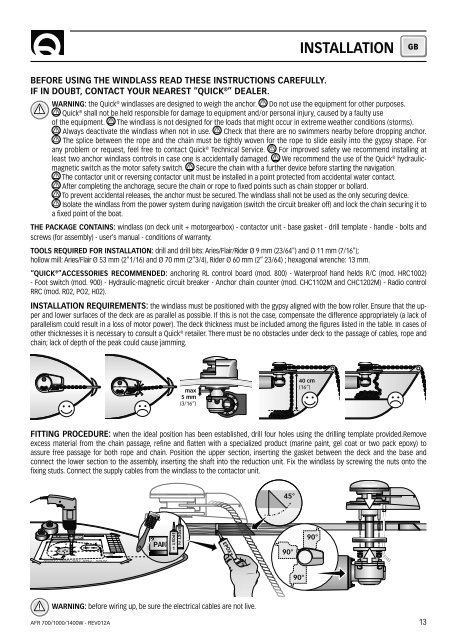
INSTALLATIONGBBEFORE USING THE WINDLASS READ THESE INSTRUCTIONS CAREFULLY.IF IN DOUBT, CONTACT YOUR NEAREST “QUICK ® ” DEALER.WARNING: the Quick ® windlasses are designed to weigh the anchor. Do not use the equipment for other purposes.Quick ® shall not be held responsible for damage to equipment and/or personal injury, caused by a faulty useof the equipment. The windlass is not designed for the loads that might occur in extreme weather conditions (storms).Always deactivate the windlass when not in use. Check that there are no swimmers nearby before dropping anchor.The splice between the rope and the chain must be tightly woven for the rope to slide easily into the gypsy shape. Forany problem or request, feel free to contact Quick ® Technical Service. For improved safety we recommend installing atleast two anchor windlass controls in case one is accidentally damaged. We recommend the use of the Quick ® hydraulicmagneticswitch as the motor safety switch. Secure the chain with a further device before starting the navigation.The contactor unit or reversing contactor unit must be installed in a point protected from accidental water contact.After completing the anchorage, secure the chain or rope to fixed points such as chain stopper or bollard.To prevent accidental releases, the anchor must be secured. The windlass shall not be used as the only securing device.Isolate the windlass from the power system during navigation (switch the circuit breaker off) and lock the chain securing it toa fixed point of the boat.THE PACKAGE CONTAINS: windlass (on deck unit + motorgearbox) - contactor unit - base gasket - drill template - handle - bolts andscrews (for assembly) - user’s manual - conditions of warranty.TOOLS REQUIRED FOR INSTALLATION: drill and drill bits: Aries/Flair/Rider Ø 9 mm (23/64") and Ø 11 mm (7/16");hollow mill: Aries/Flair Ø 53 mm (2"1/16) and Ø 70 mm (2”3/4), Rider Ø 60 mm (2” 23/64) ; hexagonal wrenche: 13 mm.“QUICK ® ”ACCESSORIES RECOMMENDED: anchoring RL control board (mod. 800) - Waterproof hand helds R/C (mod. HRC1002)- Foot switch (mod. 900) - Hydraulic-magnetic circuit breaker - Anchor chain counter (mod. CHC1102M and CHC1202M) - Radio controlRRC (mod. R02, PO2, H02).INSTALLATION REQUIREMENTS: the windlass must be positioned with the gypsy aligned with the bow roller. Ensure that the upperand lower surfaces of the deck are as parallel as possible. If this is not the case, compensate the difference appropriately (a lack ofparallelism could result in a loss of motor power). The deck thickness must be included among the figures listed in the table. In cases ofother thicknesses it is necessary to consult a Quick ® retailer. There must be no obstacles under deck to the passage of cables, rope andchain; lack of depth of the peak could cause jamming.max5 mm(3/16”)40 cm(16”)FITTING PROCEDURE: when the ideal position has been established, drill four holes using the drilling template provided.Removeexcess material from the chain passage, refine and flatten with a specialized product (marine paint, gel coat or two pack epoxy) toassure free passage for both rope and chain. Position the upper section, inserting the gasket between the deck and the base andconnect the lower section to the assembly, inserting the shaft into the reduction unit. Fix the windlass by screwing the nuts onto thefixing studs. Connect the supply cables from the windlass to the contactor unit.45°90°90°90°WARNING: before wiring up, be sure the electrical cables are not live.AFR <strong>700</strong>/<strong>1000</strong>/1400W - REV012A13