Rev. 004 A BTR 185 - Quick® SpA
Rev. 004 A BTR 185 - Quick® SpA
Rev. 004 A BTR 185 - Quick® SpA

You also want an ePaper? Increase the reach of your titles
YUMPU automatically turns print PDFs into web optimized ePapers that Google loves.
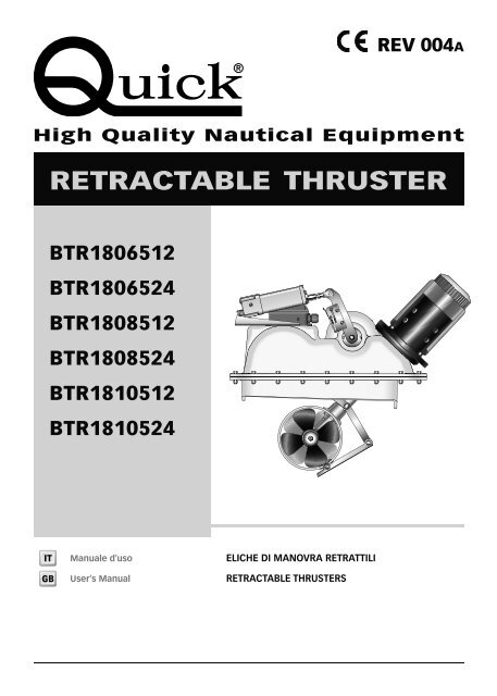
REV <strong>004</strong>AHigh Quality Nautical EquipmentRETRACTABLE THRUSTER<strong>BTR</strong>1806512<strong>BTR</strong>1806524<strong>BTR</strong>1808512<strong>BTR</strong>1808524<strong>BTR</strong>1810512<strong>BTR</strong>1810524ITGBManuale d'usoUser's ManualELICHE DI MANOVRA RETRATTILIRETRACTABLE THRUSTERS
ITINDICEPag. 4Pag. 5Pag. 6/7Pag. 8/9Pag. 10/11Pag. 12/13Pag. 14Pag. 15Pag. 16Pag. 17Pag. 18/19CARATTERISTICHE E INSTALLAZIONE - requisiti per l’installazioneINSTALLAZIONE - posizionamentoINSTALLAZIONE - localizzazione dell’installazioneINSTALLAZIONE - verifica e regolazione meccanica del sistemaINSTALLAZIONE - procedura di regolazione dell’interruttore di fine corsa di chiusura del propulsore <strong>BTR</strong>SCHEMA DI COLLEGAMENTOFUNZIONAMENTO / USO - Dip-Switch selezione opzioni - selettore rotativo attuatoreUSO / SEGNALAZIONISEGNALAZIONIAVVERTENZE IMPORTANTI - FUNZIONAMENTO / USOMANUTENZIONEGBINDEXPag. 20Pag. 21Pag. 22/23Pag. 24/25Pag. 26/27Pag. 28/29Pag. 30Pag. 28Pag. 25Pag. 26/27CHARACTERISTICS AND INSTALLATION - installation requirementsINSTALLATION - positioningINSTALLATION - installation positioningINSTALLATION - mechanical system check and adjustmentINSTALLATION - procedure for the adjustment of the closing limit switch of <strong>BTR</strong> propeller.CONNECTION DIAGRAMOPERATION/USAGE - option selection Dip-Switch - actuator current rotary switchUSAGE /NOTIFICATION SIGNSWARNING - OPERATION/USAGEMAINTENANCERETRACTABLE THRUSTER <strong>BTR</strong><strong>185</strong> DP - IT GB - REV<strong>004</strong>A 3
ITCARATTERISTICHE E INSTALLAZIONEPRIMA DI UTILIZZARE L’ELICA RETRATTILE LEGGERE ATTENTAMENTE IL PRESENTE MANUALE D'USO.IN CASO DI DUBBI CONSULTARE IL RIVENDITORE QUICK ® .ATTENZIONE: i thruster Quick ® sono stati progettati e realizzati per asservire all’uso nautico.Non utilizzare questi apparecchi per altri tipi di applicazioni.Quick ® non si assume alcuna responsabilità per i danni diretti o indiretti causati da un uso improprio dell’apparecchioo da una scorretta installazione.Il thruster non è progettato per mantenere carichi generati in particolari condizioni atmosferiche (burrasca).Si raccomanda di affidare a un professionista la predisposizione e il posizionamento del tubo allo scafo. Questeistruzioni sono generiche, e non illustrano in alcun modo i dettagli delle operazioni di predisposizione del tunnel qualecompetenza del cantiere. In caso di eventuali problemi provocati da un’installazione difettosa del tunnel, ne risponderàin pieno l’installatore. Non installare il motore elettrico nelle vicinanze di oggetti facilmente infiammabili.LA CONFEZIONE CONTIENE: elica di manovra retrattile - manuale di istruzioni - condizioni di garanzia.ACCESSORI QUICK ® CONSIGLIATI: TCD 1022 - TCD 1042 - TCD1044 - TCD1062 - TMS - TSCFMODELLI <strong>BTR</strong>1806512 <strong>BTR</strong>1806524 <strong>BTR</strong>1808512 <strong>BTR</strong>1808524 <strong>BTR</strong>1810512 <strong>BTR</strong>1810524N° Eliche 2 controrotantiTunnel Ø <strong>185</strong> mm (7” 18/64)Potenza Motore 3,3 KW 4,3 KW 6,3 KWTensione 12 V 24 V 12 V 24 V 12 V 24 V4Quick ® si riserva il diritto di apportare modifiche alle caratteristiche tecniche dell'apparecchio e al contenuto di questo manuale senza alcun preavviso.In caso di discordanze o eventuali errori tra il testo tradotto e quello originario in italiano, fare riferimento al testo italiano o inglese.Sezione cavi2 x 50mm 2(2 x AWG 1)50mm 2(AWG 1)2 x 70mm 2(2 x AWG 2/0)2 x 50mm 2(2 x AWG 1)2 x 95mm 2(2 x AWG 3/0)2 x 50mm 2(2 x AWG 1)Fusibile 355A 200A 500A 355A 2 x 325 A 400ASpinta 65 kgf (143,3 lb) 85 kgf (187,4 lb) 105 kgf (231,5 lb)Peso 38,5 kg (84,9 lb) 42,5 kg (93,7 lb) 47,5 kg (104,7 lb)REQUISITI PER L'INSTALLAZIONECome già introdotto, nonostante tutti i componenti e gli organi meccanici in movimento siano di elevata qualità, la correttainstallazione dell’unità propulsiva retrattile è fondamento irrinunciabile ad un sicuro ed efficace utilizzo dell’imbarcazioneoltre che della stessa unità propulsiva.Si fà nota che l’installazione di tale unità è un’operazione che richiede esperienza oltre che competenza tecnica. Si raccomandadi affidare l’installazione a personale competente e di consultare il costruttore o architetti navali per valutareappieno l’entità dei lavori.L’elica retrattile Quick ® ha due movimenti separati.Il movimento principale, relativo alla parte propulsiva, è di tipo basculante. Le cerniere su cui avviene il movimentosono concepite per conferire elevata resistenza all’assieme e sono localizzate sul piano della flangiatura piana che lega lastruttura preassemblata al supporto solidale alla carena.Il movimento secondario è relativo al movimento di chiusura del passascafo da cui esce il tunnel. Questo movimento èdel tipo a parallelogramma e la sua escursione non è una semplice rivoluzione attorno al pivot principale bensì un movimentoatto ad estromettere senza interferenze la piastra di chiusura dal foro praticato nello scafo.Motore elettrico, riduttore, leverismi e tutti gli altri componenti sono forniti da Quick ® già assemblati sulla struttura portantein GRP e non necessitano regolazioni, adattamenti o sigillature ove non sia indicato in questo manuale.L’elica retrattile Quick ® è venduta separatamente dalla controflangia che può essere fornita in diversi materiali per risponderealla diversa tipologia di scafi. Quick ® è in grado di fornire supporti in acciaio inossidabile, lega d’alluminio o GRP,fondamentali per una installazione veloce, solida e precisa.Per le carene in vetroresina il supporto deve essere laminato nello scafo rispettando le vigenti norme in materia digiunzioni. L’unità propulsiva distribuisce sollecitazioni meccaniche allo scafo attraverso la controflangia. La forza dellagiunzione sarà determinata da laminazioni sovrapposte, realizzate a “regola d’arte”.Per carene in lega d’alluminio come per carene in acciaio inossidabile, il supporto dovrà essere saldato allo scafo.Se ben realizzata, l’installazione di una struttura scatolata come quella del supporto può conferire maggior robustezzaallo scafo. Consultare il costruttore, architetti navali e/o ditte specializzate per valutare opere aggiuntive quali traversi ecentine in prossimità della posizione dell’unità propulsiva retrattile.RETRACTABLE THRUSTER <strong>BTR</strong><strong>185</strong> DP - IT GB - REV<strong>004</strong>A
INSTALLAZIONEITPosizionamentominimo 0,75 volteØ tunnel• Per evitare fenomeni di cavitazione nell’elica, si dovrà posizionare il tunnel più a fondo possibile.BABARICENTROABL 1L 2L 1L 2• L’effetto di leva nell’imbarcazione è proporzionale all’aumento della distanza (L1 e L2) che si rileva, tra il baricentro e laposizione del tunnel A e B (poppa/prua).FPer avere maggiore effetto leva preferire la posizione B alla posizione A.RETRACTABLE THRUSTER <strong>BTR</strong><strong>185</strong> DP - IT GB - REV<strong>004</strong>A5
ITINSTALLAZIONELocalizzazione dell’installazioneAccedere direttamente nella parte interna dello scafo, nella zona in cui il propulsore verrà installato.FLa posizione del propulsore dovrà permettere agevoli manovre di installazione.Fig. 1PROPULSORE CHIUSOSCAFOX Y ZREFPIASTRA METALLICAPosizionare il propulsore, in posizione di riposo (chiuso), all’interno dello scafo facendolo appoggiare sulla piastra metallicasolidale al tunnel. Rilevare le altezze (X Y Z) che intercorrono tra la parte inferiore della flangiatura e lo scafo.Realizzare dei riferimenti (REF) che permettano, una volta rimosso il propulsore, di sistemare il supporto nella stessaposizione.Fig. 2SUPPORTOX Y ZCUT LINECUT LINERiportare le altezze (X Y Z) rilevate sul lato maggiore del supporto.Ripetere l’operazione per rilevare anche le altezze dei lati minori ed adattare il supporto alla forma dello scafo.Una volta rifilato il supporto, bloccarlo temporaneamente nella posizione contrassegnata (REF) per permettere le verifichedegli ingombri finali.Fig. 3aFig. 3b350 mm280 mmVerificata la corretta posizione, contrassegnare sullo scafo la sagoma interna del supporto (Fig.3a).Rimuovere il supporto, misurare e segnare l’apertura dello scafo usando le dimensioni riportate sulla figura 3b.6RETRACTABLE THRUSTER <strong>BTR</strong><strong>185</strong> DP - IT GB - REV<strong>004</strong>A
INSTALLAZIONEITFig. 4Realizzare l’apertura nello scafo, per il passaggio del tunnel, tagliando loscafo lungo il perimetro tracciato.Fig. 5Allineare il supporto alla posizione prestabilita e resinarlo, saldarlo nelcaso dell’alluminio o dell’acciaio, secondo le tecniche identificate comele più idonee al tipo di costruzione della carena.Fig. 6PROPULSOREBULLONERONDELLAO-RINGRONDELLADADOSUPPORTOSCAFOAssemblare il propulsore al supporto, ora solidale allo scafo, con le viterie in dotazione, verificando il corretto posizionamentodell’O-ring nella sede del supporto.RETRACTABLE THRUSTER <strong>BTR</strong><strong>185</strong> DP - IT GB - REV<strong>004</strong>A7
ITINSTALLAZIONEVERIFICA E REGOLAZIONE MECCANICA DEL SISTEMARealizzare secondo le più opportune tecniche un coperchio di chiusura dell’apertura sulla carena e fissarlo al piatto metallicosolidale al tunnel dell’unità retrattile.Attenersi alla sequenza riportata di seguito per effettuare la verifica dell’apertura del portello:1) Il propulsore <strong>BTR</strong> non deve essere alimentato.2) Sfilare l’anello e rimuovere il perno (fig. 7 / part. A), sganciare l’attuatore dalla leva (part. B), assicurarsi che il sistema apantografo sia libero di aprirsi e chiudersi senza impedimenti meccanici (muovendo manualmente la leva C).FIG. 7ABC8RETRACTABLE THRUSTER <strong>BTR</strong><strong>185</strong> DP - IT GB - REV<strong>004</strong>A
INSTALLAZIONEITL’ATTUATORE È GIÀ STATOPRE-TARATO IN FASE DIASSEMBLAGGIO.NON MANOMETTERETENTANDO DI GIRARELE VITI PRESENTI SULLATESTATA O RUOTANDO LOSTELO DELL’ATTUATORE.RETRACTABLE THRUSTER <strong>BTR</strong><strong>185</strong> DP - IT GB - REV<strong>004</strong>A9
ITINSTALLAZIONEATTENZIONE: prestare particolare attenzione ad evitare interferenze tra il coperchio e l’apertura dello scafo.Contatti troppo precisi provocheranno danni all’intero sistema di movimento.3) Riagganciare l’attuatore alla leva inserendo il perno di blocco.Verificato meccanicamente il sistema procedere con la regolazione di fine corsa.PROCEDURA DI REGOLAZIONE DELL’INTERRUTTORE DI FINE CORSA DI CHIUSURA DEL PROPULSORE <strong>BTR</strong>ATTENZIONE: la seguente procedura deve essere eseguita da personale qualificato.ATTENZIONE: presenza di parti meccaniche in movimento. Porre particolare attenzione quando si opera sulpropulsore <strong>BTR</strong> se è alimentato.4) Assicurarsi che tutti i collegamenti elettrici siano stati compiuti inmaniera corretta.5) Rimuovere il coperchio dal contenitore della scheda.FIG. 8CAN2UPDWNPer eseguire le regolazioni dei fine corsa bisogna entrare in“modalità manuale”.6) Tenendo premuti entrambi i pulsanti presenti sulla scheda (fig. 8 /part. A) alimentare la scheda elettronica RTC R1 fino a che il LEDPOWER (verde) lampeggerà velocemente (fig. 8 / part. B).Dopodichè rilasciare entrambi i pulsanti.7) Premere il pulsante DOWN per effettuare l’apertura dell’elica finchèil LED LA STATUS diventerà di colore verde.8) Premere il pulsante UP per effettuare la chiusura dell’elica fino allampeggio del LED ERROR (rosso).ABCDPOWERLA STATUSERROR10RETRACTABLE THRUSTER <strong>BTR</strong><strong>185</strong> DP - IT GB - REV<strong>004</strong>A
INSTALLAZIONEIT9) Regolare il fine corsa sollevandolo verso l’alto (fig. 9 / part. A) facendo toccare la sua leva (B) sul cilindro dell’attuatorefino a che il LED LA STATUS diventerà di colore rosso.FIG. 9BAAFIG. 1010) Fissare l’interruttore di fine corsa in questa posizione agendo sulleviti di serraggio (fig. 10 / part. A).11) Interrompere l’alimentazione al propulsore <strong>BTR</strong> per almeno cinquesecondi (fig. 11) (in questo modo si resetta l’errore di elevatoassorbimento).12) Alimentare il propulsore <strong>BTR</strong>.FIG. 1101213) Abilitare un comando TCD collegato al propulsore <strong>BTR</strong> (fig. 12) peraprire il propulsore e renderlo operativo.14) Disabilitare il comando TCD in precedenza abilitato per chiudere ilpropulsore.15) Verificare che la chiusura del propulsore sia avvenuta correttamentee nella posizione voluta controllando che il LED LA STATUSsia di colore rosso (fig. 8 / part. C).FIG. 1216) Accertarsi che la protezione di elevato assorbimento non sia intervenuta(il LED ERROR deve essere spento - fig. 8 / Part. D).Nel caso in cui sia necessario mantenere leggermente aperto il portellodi chiusura del propulsore <strong>BTR</strong>, spostare l’interruttore finecorsa dichiusura verso l’alto. Una volta effettuata questa regolazione ripeterei punti 12, 13, 14, 15, 16 della procedura.RETRACTABLE THRUSTER <strong>BTR</strong><strong>185</strong> DP - IT GB - REV<strong>004</strong>A11
BOWSTERNITSCHEMA DI COLLEGAMENTOSISTEMA BASE <strong>BTR</strong><strong>185</strong>Esempio di collegamentoACCESSORI QUICK ® PER L'AZIONAMENTODELL’ELICA DI MANOVRA RETRATTILEPANNELLI DI COMANDOTCD 1022 TCD 1042 TCD 1044 TCD 1062TCD 1042TCD 1022COMANDOINTERRUTTUREDI LINEA TSCINTERRUTTORE BATTERIEPARALLELO-SERIE PSSROSSONEROROSSOINTERRUTTOREDI LINEA TMSNEROINTERRUTTOREAS-SXM1+M2-DXASSTACCA-BATTERIAMOTOREFUSIBILERAPIDO 4A*ALLA BATTERIASERVIZIPROLUNGHE(OPZIONALI)SDOPPIATORE(OPZIONALE)6SCHEDAELETTRONICARTC R13 4 1 257*BATTERIA12/24VFUSIBILEVEDI TABELLAA PAG.4FUSIBILERAPIDO 10AINTERRUTTOREFINE CORSAESTERNOALLA BATTERIASERVIZI*ATTUATORE* NEGATIVO DEI GRUPPI BATTERIA IN COMUNE.12RETRACTABLE THRUSTER <strong>BTR</strong><strong>185</strong> DP - IT GB - REV<strong>004</strong>A
SCHEMA DI COLLEGAMENTOITSCHEDA RTC R110 ACN2M7654321UPDWNCAN2CN3LA+ LA- LSC COM LSO COM I-DX I-SX C-DX C-SX C-COMDL3POWERDL2LA STATUSDL1ERRORCAN1Selettore rotativocorrente attuatoreDip-Switchselezione opzioniFusibile attuatoreFine corsaesternoPulsanti movimento manualeBluNeroBiancoCN1GialloMarroneRossoRosaLED verde alimentazionecollegamento CAN busLED bicolore stato attuatoreATTUATORE LINEARELED rosso segnalazione problemiNegativo gruppo teleinvertitoreAl teleruttore SXAl teleruttore DXConnettore femmina TCD contatto 2Connettore femmina TCD contatto 1Negativo AlimentazionePositivo AlimentazioneNeroRETRACTABLE THRUSTER <strong>BTR</strong><strong>185</strong> DP - IT GB - REV<strong>004</strong>A13
ITFUNZIONAMENTO / USODIP-SWITCH SELEZIONE OPZIONISWITCH FUNZIONE DESCRIZIONEON1 Riservata (mantenere sempre OFF)1 2 3 42Indica alla stazione di comando CAN che il propulsore è di prua (OFF)Indica alla stazione di comando CAN che il propulsore è di poppa (ON)ON1 2 3 4ON1 2 3 43 Riservata (mantenere sempre OFF)4 Riservata (mantenere sempre OFF)ON1 2 3 4ON1 2 3 4IMPOSTAZIONE DI FABBRICA: 1 = OFF , 2 = OFF , 3 = OFF , 4 = OFFSELETTORE ROTATIVO CORRENTE ATTUATOREI dieci passi selezionabili (da 0 a 9) permettono di impostare una percentuale (vedi tabella) riferita alla corrente/caricomassimo permesso per l’attuatore in uso.POSIZIONE SELETTOREROTATIVO% CORRENTE/CARICO MASSIMO0 28%1 36%2 44%3 52%4 60%5 68%6 76%7 84%8 92%9 100%IMPOSTAZIONE DI FABBRICA: posizione = 514RETRACTABLE THRUSTER <strong>BTR</strong><strong>185</strong> DP - IT GB - REV<strong>004</strong>A
USO / SEGNALAZIONIITQualora sia richiesta una impostazione diversa da quella di fabbrica effettuare le seguenti operazioni:1) Con la scheda non alimentata posizionare la freccia del selettore rotativo nella posizione voluta.2) Alimentando la scheda, verrà automaticamente settata la percentuale corrispondente alla posizione selezionata.Se il limite di corrente/carico massimo è troppo basso rispetto alle reali esigenze di utilizzo potrebbero intervenire le protezionicontro l’elevato assorbimento dell’arttuatore in chiusura e apertura della retrattile con lampeggio di errore 1 e 7.SEGNALAZIONIDi seguito si riporta il significato delle segnalazioni lunimose fornite dalla scheda RTC R1 (vedi scheda elettronica apag.13).LED POWER (verde)STATO LEDSPENTOLAMPEGGIO BREVELAMPEGGIO VELOCEACCESO CON BREVESPEGNIMENTOACCESODESCRIZIONEScheda non alimentataScheda alimentata ma comando non abilitatoScheda alimentata e modalità movimento attuatore manuale attivaScheda alimentata ma comando non abilitato e link attivo con la stazione di comando CANScheda alimentata e comando abilitato (TCD o stazione CAN).LED LA STATUS (bicolore)COLORE LED STATO LED DESCRIZIONE- SPENTOCon scheda alimentata, modalità movimento attuatore manuale attiva eanomalia fine corsa presenteROSSO ACCESO Retrattile chiusa (fine corsa LSC attivo)VERDE ACCESO Retrattile aperta (fine corsa LSO attivo)ARANCIO ACCESO Retrattile ne aperta ne chiusa (fine corsa LSC e LSO non attivi)ARANCIO LAMPEGGIANTERetrattile ne aperta ne chiusa (fine corsa LSC e LSO non attivi) ed attuatorelineare in movimento.RETRACTABLE THRUSTER <strong>BTR</strong><strong>185</strong> DP - IT GB - REV<strong>004</strong>A15
ITSEGNALAZIONILED ERROR (rosso)NUMERO LAMPEGGINESSUNO123456789DESCRIZIONENessuna anomalia presente.Elevato assorbimento attuatore in salita (chiusura retrattile).La segnalazione avviene dopo che il sistema ha effettuato, in presenza di un attrito meccanicosuperiore alla soglia impostata, tre tentativi di risalita. Il problema può essere causato da uncorpo estraneo entrato nel meccanismo, dall’imbarcazione in navigazione a velocità sostenuta,o da problemi meccanici della retrattile e relativo portello.Fusibile aperto.Si è verificato un assorbimento di corrente superiore a 10A. Il problema si può presentare inpresenza di un cortocircuito o di un sovraccarico sulla linea elettrica dell’attuatore. Verificare ilcablaggio delle linee elettriche dalla scheda all’attuatore o l’assorbimento dell’attuatore stesso.Condizione anomala finecorsa.Il problema è segnalato nel caso in cui la scheda rilevi una anomalia sui fine corsa (entrambi attivati).Verificare il cablaggio della linea elettrica dalla scheda ai fine corsa e la loro funzionalità.Interruzione linea comando attuatore.Il problema è segnalato nel caso in cui la scheda rilevi una interruzione della linea elettrica dicomando dell’attuatore. Verificare il cablaggio delle linee elettriche della scheda all’attuatoreIntervento timeout movimentazione attuatore.Il problema è segnalato nel caso in cui, la movimentazione impartita all’attuatore non è eseguita,entro un periodo di 15 secondi.Errata configurazione dip-switch.Il problema è segnalato nel caso in cui le posizioni del dip-switch non siano settate correttamente.Elevato assorbimento attuatore in discesa (apertura retrattile).La segnalazione avviene dopo che il sistema ha effettuato, in presenza di un attrito meccanicosuperiore alla soglia impostata, tre tentativi di discesa. Il problema può essere causato da uncorpo estraneo entrato nel meccanismo, dall’imbarcazione in navigazione a velocità sostenuta,o da problemi meccanici della retrattile e del relativo portello.Elevato assorbimento uscita comando teleinvertitore motore.Il problema è segnalato nel caso in cui la scheda rilevi un cortocircuito o un sovraccarico sullalinea elettrica di comando del propulsore.Verificare il cablaggio delle linee elettriche della scheda al propulsore e l’assorbimento del gruppoteleinvertitore motore installato sul propulsore.Interruzione collegamento uscita comando teleinvertitore motore.Il problema è segnalato nel caso in cui la scheda rilevi una interruzione della linea elettrica dicomando al propulsore.Verificare il cablaggio delle linee elettriche della scheda al gruppo tele invertitore motore installatosul propulsore.Al temine della sequenza ciclica di lampeggio il LED ERROR rimane spento per un breve periodo.16RETRACTABLE THRUSTER <strong>BTR</strong><strong>185</strong> DP - IT GB - REV<strong>004</strong>A
AVVERTENZE - FUNZIONAMENTO/USOITAVVERTENZE IMPORTANTIATTENZIONE: accertarsi che non vi siano bagnanti ed oggetti galleggianti nelle vicinanze, prima di avviare l’elicaretrattile.ATTENZIONE: si raccomanda, per non danneggiare il sistema, di non navigare con l’elica retrattile aperta.FUNZIONAMENTO / USO DELL’ELICA RETRATTILEPer il corretto uso della retrattile riferirsi al manuale del comando TCDAccensioneAll’accensione la scheda RTC R1 verifica la posizione in cui si trova la retrattile (alzata, abbassata o in posizione intermedia).Nel caso in cui sia alzata, il sistema non compie azioni.Nel caso in cui sia abbassata o in posizione intermedia, comanderà la risalita della retrattile.Comando abilitazione da TCD (Discesa elica retrattile)Quando la scheda RTC R1 riceve l’abilitazione da un comando TCD, inizia la procedura di discesa della retrattile.Fino a quando questa procedura non è stata completata i comandi destra/sinistra provenienti dal TCD saranno inibiti.Durante la fase di discesa la scheda RTC R1 misura la corrente assorbita dall’attuatore lineare.Se a causa di un attrito meccanico vi è un elevato assorbimento dell’attuatore lineare, la discesa verrà invertita per unbreve periodo per poi riprendere.Dopo 3 tentativi, la scheda RTC R1 segnalerà il problema.Comando disabilitazione da TCD (Salita elica retrattile)Quando la scheda RTC R1 riceve la disabilitazione da un comando TCD, inizia la procedura di salita della retrattile.In risalita i comandi destra/sinistra provenienti dal TCD saranno inibiti.Durante la fase di salita la scheda RTC R1 misura la corrente assorbita dall’attuatore lineare.Se a causa di un attrito meccanico vi è un elevato assorbimento dell’attuatore lineare, la salita verrà invertita per unbreve periodo per poi riprendere.Dopo 3 tentativi, la scheda RTC R1 segnalerà il problema.La chiusura dell’elica è da effettuare entro una velocità massima di due nodi, in relazione alle correnti.Salita automatica in caso di inutilizzoCon elica abbassata, dopo 6 minuti dall’ultimo comando DX o SX del TCD, l’elica retrattile esegue la procedura di salita.Rilevamento errori dal TMSNel caso il TMS mandi in rete un segnale di errore (problema teleinvertitore o sovratemperatura motore), l’elica retrattileesegue la procedura di salita.Interruttore di Linea (TSC)Nel caso in cui sulla linea fosse presente il TSC, alla pressione del fungo l’elica retrattile esegue la procedura di salita.Rilevamento errori dal TCDNel caso il TCD mandi in rete un segnale di errore (comando prolungato, interruzione linea, corto circuito in uscita DX oSX), l’elica retrattile esegue la procedura di salita.RETRACTABLE THRUSTER <strong>BTR</strong><strong>185</strong> DP - IT GB - REV<strong>004</strong>A17
ITMANUTENZIONE12<strong>BTR</strong> 1806512<strong>BTR</strong> 1806524<strong>BTR</strong> 1808512<strong>BTR</strong> 1808524<strong>BTR</strong> 1810512<strong>BTR</strong> 18105244356171612151489181971089111314151618RETRACTABLE THRUSTER <strong>BTR</strong><strong>185</strong> DP - IT GB - REV<strong>004</strong>A
MANUTENZIONEITPOS. DENOMINAZIONE CODICE1 Vite fissaggio motore MBV1025MXCEO2 Rondella fissaggio motore MBR10X0000003A Motore 3KW 12V EMFEL30120003B Motore 3KW 24V EMFEL30240003C Motore 4KW 12V EMFEL40120003D Motore 4KW 24V EMFEL40240003E Motore 6KW 12V EMFEL60120003F Motore 6KW 24V EMFEL60240<strong>004</strong>A Cassetta teleinvertitori150A 12VERBTQ12150<strong>004</strong>B Cassetta teleinvertitori150A 24VERBTQ24150<strong>004</strong>C Cassetta teleinvertitori350A 12VERBTQ12350<strong>004</strong>D Cassetta teleinvertitori350A 24VERBTQ24350005A Carter cassettateleinvertitorePCCCBTQA00005B Carter cassettateleinvertitoriPCCCBTQB00006 Fissaggio carter cassettateleinvertitoriPBD04STPN0007A Attuatore lineare 12V EAL140M030127B Attuatore lineare 24V EAL140M030248 Anello a molla MBA20MZ000009 Rondella Ø8 MBR08X00000010 Perno MEP8275TP14X11 Perno MEP8385TP14X12 Spina trascinamento elica MBSC05025A0013 Elica RH PVEL<strong>185</strong>0000014 Dado fissaggio elica MBD12MXET00015 Puntale anodico MMANBTQ<strong>185</strong>0016 Vite fissaggiopuntale anodicoMBV0625MXCE017 Elica LH PVEL<strong>185</strong>L000018 Vite M5*12 inox MBR0512MXCE019 Anodo per elica <strong>BTR</strong> MANBTQR6015ATTENZIONE: accertarsi che non sia presente l’alimentazioneal motore elettrico quando si eseguono le operazionidi manutenzione.I Thruster Quick ® sono costituiti da materiale resistenti all’ambientemarino: è indispensabile, in ogni caso, rimuovere periodicamentei depositi di sale che si formano sulle superficiesterne per evitare corrosioni e di conseguenza inefficienzadel sistema.Smontare una volta all’anno, seguendo i seguenti punti:• Tenere eliche (13 e 17) e piede riduttore puliti.• Verniciare le eliche e il piede riduttore con vernice antivegetativa,prima di ogni stagione.ATTENZIONE: non verniciare gli anodi di zinco (15 e 19),le sigillature e gli alberi delle eliche. Fare attenzione anon far penetrare la vernice nelle “piste” del piede riduttorenelle quali si muove il mozzo dell’elica.• Controllare gli anodi di zinco (15 e 19) frequentemente.• Sostituire l’anodo di zinco prima di ogni stagione o quando èconsumato per più della metà.• Accertarsi dopo ogni manutenzione, che tutte le viti siano benstrette.• Accertarsi dopo ogni manutenzione che le eliche (13 e 17)siano ben fissate e le viti (1) che fissano il motore elettrico (3)siano ben strette.• Accertarsi che tutti i collegamenti elettrici siano puliti e fissatisaldamente.• Accertarsi che le batterie siano in buone condizione.RETRACTABLE THRUSTER <strong>BTR</strong><strong>185</strong> DP - IT GB - REV<strong>004</strong>A19
GBCHARACTERISTICS AND INSTALLATIONBEFORE USING THE RETRACTABLE THRUSTER, CAREFULLY READ THIS USER MANUAL.IF IN DOUBT, CONTACT YOUR NEAREST QUICK ® DEALER.WARNING: the thruster Quick ® have been designed and manufactured for nautical use.Do not use these appliances for other uses.Quick ® shall accept no responsibility for direct or indirect damages caused by improper use of the appliance oran improper installation.The thruster is not designed for maintaining loads generated in particular atmospheric conditions (storms).It is recommended to entrust arrangement and positioning of the tube on the hull to a professional. These aregeneral instructions and do not, in any way, illustrate details of the tunnel arrangement operations, which competenceis of the boatyard. The installer will be fully responsible for any damages caused by a faulty installation ofthe tunnel. Do not install the electric motor near easily inflammable objects.THE PACKAGE CONTAINS: retractable thruster - user's manual - conditions of warranty.QUICK ® ”ACCESSORIES RECOMMENDED: TCD 1022 - TCD 1042 - TCD1044 - TCD1062 - TMS - TSCFMODELS <strong>BTR</strong>1806512 <strong>BTR</strong>1806524 <strong>BTR</strong>1808512 <strong>BTR</strong>1808524 <strong>BTR</strong>1810512 <strong>BTR</strong>1810524N° Propellers 2 contra-rotatingTunnel Ø <strong>185</strong> mm (7” 18/64)Motor Power 3,0 KW 4,0 KW 6,0 KWVoltage 12 V 24 V 12 V 24 V 12 V 24 VSection of wire20Quick ® reserves the right to introduce changes to the equipment and the contents of this manual without prior notice.In case of discordance or errors in translation between the translated version and the original text in the Italian language, reference will be made to the Italian or English text.2 x 50mm 2(2 x AWG 1)50mm 2(AWG 1)2 x 70mm 2(2 x AWG 2/0)2 x 50mm 2(2 x AWG 1)2 x 95mm 2(2 x AWG 3/0)2 x 50mm 2(2 x AWG 1)Fuse 355A 200A 500A 355A 2 x 325 A 400AThrust 65 kgf (143,3 lb) 85 kgf (187,4 lb) 105 kgf (231,5 lb)Weight 38,5 kg (84,9 lb) 42,5 kg (93,7 lb) 47,5 kg (104,7 lb)INSTALLATION REQUISITESAs said, despite all components and moving mechanical parts are of high quality, the correct installation of the retractablepropulsion unit is fundamental for a safe and efficient use of the boat, as well as of the same propulsion unit.Please note that the installation of such unit is an operation requiring experience as well as technical competence. It isrecommended to entrust the installation to competent staff and to consult the manufacturer or naval architects to fullyevaluate the entity of the work.The Quick retractable thruster ® has two individual movements.The main movement, relating to the propulsion part, is of tilting type. The hinges on which the movement happens areconceived to confer high resistance to the set and are located on the flat flange surface that joins the pre-assembledstructure to the hull solid support.The secondary movement relates to the closing of the through-hull fitting from where the tunnel exits. This movement isof parallel link type and its range is not a simple revolution around the main pivot but a movement act at expelling, withoutinterferences, the closing plate from the hole made in the hull.Electric motor, gear, levers and all other components are supplied by Quick ® , already assembled on the supporting structurein GRP and do not require adjustments, adaptations or sealing, unless indicated in this manual.The Quick retractable thruster ® is sold separately from the counter flange, that can be supplied in different materials tocomply with the different types of hulls. Quick ® is able to supply stainless steel, aluminium alloy or GRP supports, fundamentalfor quick, solid and precise installation.For the fibreglass hulls the support must be laminate in the hull respecting the current Standards relating to joints.The propulsion unit distributes mechanical stresses to the hull through the counter flange. The force of the joint will bedetermined by overlapped, up to standard, laminates.For aluminium alloy hulls, like for stainless steel hulls, the support must be welded to the hull.If correct, the installation of a boxed structure like that of the support, can give greater sturdiness to the hull. Consult themanufacturer, naval architects and/or specialised companies to evaluate additional work which beams and ribs near theretractable propulsion unit.RETRACTABLE THRUSTER <strong>BTR</strong><strong>185</strong> DP - IT GB - REV<strong>004</strong>A
INSTALLATIONGBPositioningminimum 0,75times Ø tunnel• To avoid cavitation in the propeller, the tunnel must be positioned as low as possible.BABARYCENTREABL 1L 2L 1L 2• The lever effect in the boat is proportional to the distance increase (L1 and L2) detected between the barycentre andthe position of tunnel A and B (bow/stern).FFor greater lever effect prefer position B to position A.RETRACTABLE THRUSTER <strong>BTR</strong><strong>185</strong> DP - IT GB - REV<strong>004</strong>A21
GBINSTALLATIONInstallation positioningDirectly access inside the hull, where the thruster will be installed.FThe thruster position must enable easy maintenance operations.Fig. 1CLOSED THRUSTERHULLX Y ZREFMETAL PLATEPosition the thruster in stand-by position (closed) inside the hull, making it rest on the metal plate integral to the tunnel.Detect the heights (X Y Z) between the lower part of the flange and the hull. Realise references (REF) that, once thethruster is removed, enable arranging the support in the same position.Fig. 2SUPPORTX Y ZHULLCUT LINERecord the heights (X Y Z) detected on the larger side of the support.Repeat the operation to also detect the heights of the shorter sides and adapt the support to the shape of the hull. Oncetrimmed the support, temporarily lock in position marked (REF) to enable verifications of the final dimensions.Fig. 3aFig. 3b350 mm280 mmOnce the correct position is verified, mark the hull with the internal shape of the support (Fig. 3a).Remove the support, measure and mark the hull opening using the dimensions in figure 3b.22RETRACTABLE THRUSTER <strong>BTR</strong><strong>185</strong> DP - IT GB - REV<strong>004</strong>A
INSTALLATIONGBFig. 4Realise the opening in the hull for tunnel passage, by cutting the hull alongthe outlined perimeter.Fig. 5Align the support to the pre-established position and resin it, weld it incase of aluminium or steel, according to the techniques identified as mostsuitable for the type of hull construction.Fig. 6THRUSTERBOLTWASHERO-RINGWASHERNUTSUPPORTHULLAssemble the thruster to support, now integral with the hull, using the provided bolts and screws, verifying the correctpositioning of the o-ring in the support.RETRACTABLE THRUSTER <strong>BTR</strong><strong>185</strong> DP - IT GB - REV<strong>004</strong>A23
GBINSTALLATIONSYSTEM CHECK AND MECHANIC ADJUSTMENTAccording to the most opportune techniques, realise a closing lid of the opening on the hull and fix it to the solid metalplate to tunnel of the retractable unit.Follow the sequence described below to verify the opening of the hatch:1) The <strong>BTR</strong> propeller should be disconnected from power.2) Take the ring off and remove the pin (fig. 7 / part A), unhook the actuator from the lever (part. B), ensure that thepantograph system is free to open and close without any mechanical obstacle (manually moving the C lever).FIG. 7ABC24RETRACTABLE THRUSTER <strong>BTR</strong><strong>185</strong> DP - IT GB - REV<strong>004</strong>A
INSTALLATIONGBTHE ACTUATOR HASALREADY BEEN PRE-SETDURING ASSEMBLING.DO NOT TAMPERBY TRYING TO TURN THESCREWS ON THE HEAD,OR BY ROTATING THEACTUATOR’S STEM.RETRACTABLE THRUSTER <strong>BTR</strong><strong>185</strong> DP - IT GB - REV<strong>004</strong>A25
GBINSTALLATIONWARNING: pay particular attention to avoid interferences between the lid and the hull opening. Too precise contactswill cause damages to the entire moving system.3) Fix the actuator on the lever again, by inserting the lock pin.Once the system has been mechanically verified, proceed to adjust the limit switch.PROCEDURE FOR THE ADJUSTMENT OF THE CLOSING LIMIT SWITCH OF <strong>BTR</strong> PROPELLER.WARNING: the following procedure must be carried out by qualified personnel.WARNING: presence of moving mechanical parts. Pay extreme attention when operating on the <strong>BTR</strong> propeller ifconnected to power.4) Ensure that all electrical connections have been properly carriedout.5) Remove the cover from the card box.FIG. 8CAN2UPDWNLimit switch adjustments must be made in “manual mode”.6) Holding down both buttons on the board(fig. 8 / part. A), connectpower to the RTC R1 electronic control board until the (green)POWER LED begins flashing rapidly (fig. 8 / part. B).Then release both buttons.7) Push the “DOWN” button to open the thruster, as long as the LASTATUS LED will become green.8) Push the “UP” button to close the thruster until the ERROR LED(Red) flashes.ABCDPOWERLA STATUSERROR26RETRACTABLE THRUSTER <strong>BTR</strong><strong>185</strong> DP - IT GB - REV<strong>004</strong>A
INSTALLATIONGB9) Adjust the limit switch by lifting it upwards (fig. 9 / part A) making the lever (B) touch the actuator’s cylinder till the “LASTATUS” LED becomes red.FIG. 9BAAFIG. 1010) Fix the limit switch in this position by operating on the tighteningscrews (fig. 10 / part. A).11) Disconnect the <strong>BTR</strong> propeller from power for at least five seconds(fig. 11) (in order to reset the high-absorption error).FIG. 1112) Connect power to the <strong>BTR</strong> propeller.13) Enable a TCD control connected to the <strong>BTR</strong> propeller (fig. 12) toopen the propeller and activate it.01214) Disable the TCD control beforehand enabled in order to close thepropeller.15) Verify that the propeller has closed properly and in the desiredposition. The “LA STATUS” LED must be red (fig. 8 / part. C).16) Ensure that the high-absorption protection did not intervene (the“ERROR” LED must be switched off - fig. 8 / Part. D).FIG. 12In case the <strong>BTR</strong> propeller closing lid needs to be kept slightly open,move the limit switch upwards. Once this adjustment has been done,repeat step 12, 13, 14, 15, 16 of the procedure.RETRACTABLE THRUSTER <strong>BTR</strong><strong>185</strong> DP - IT GB - REV<strong>004</strong>A27
BOWSTERNGBCONNECTION DIAGRAMBASIC SYSTEM <strong>BTR</strong><strong>185</strong>Connection exampleQUICK ® ACCESSORIES FOR ACTIVATIONOF THE RETRACTABLE THRUSTERCONTROL PANELSTCD 1022 TCD 1042 TCD 1044 TCD 1062TCD 1042TSC LINE SWITCHCONTROLTCD 1022PSS PARALLEL-SERIESBATTERY SWITCHREDBLACKREDTMSTHRUSTERMAIN SWITCHBLACKAM1+M2ABATTERYISOLATORSWITCH-SX-DXSSMOTORFUSE 4AQUICK ACTING F*TO THE SERVICESBATTERYCONTROL CABLEEXTENSIONS(OPTIONALS)SPLITTER(OPTIONAL)6RTC R1ELECTRONICBOARD3 4 1 257*BATTERY12/24VFUSESEE TABLEON PAGE 20FUSE 10AQUICK ACTING FSWITCHEXTERNALLIMIT SWITCHTO THE SERVICESBATTERY*ACTUATOR* COMMON NEGATIVE FOR THE BATTERY GROUPS.28RETRACTABLE THRUSTER <strong>BTR</strong><strong>185</strong> DP - IT GB - REV<strong>004</strong>A
CONNECTION DIAGRAMGBRTC R1 BOARD10 ACN2M7654321UPDWNCAN2CN3LA+ LA- LSC COM LSO COM I-DX I-SX C-DX C-SX C-COMDL3POWERDL2LA STATUSDL1ERRORCAN1CN1Rotary switchactuator current limitBrownDip-Switchoptions selectionFuse ActuatorExternallimit switchManual operation buttonsBlueBlackWhiteYellowPinkGreen LED powerCAN bus linkBi-colour LED linear actuator statusRed LED errorsLINEAR ACTUATORNegative group reversing contactorTo left contactorTo right contactorTCD Plugin female Pin 2TCD Plugin female Pin 1- Power Supply+ Power SupplyBlackRedRETRACTABLE THRUSTER <strong>BTR</strong><strong>185</strong> DP - IT GB - REV<strong>004</strong>A29
GBOPERATING / USAGEOPTION SELECTION DIP-SWITCHSWITCH FUNCTION DESCRIZIONEON1 Reserved (always keep off)1 2 3 42Informs the CAN control station that the thruster is in the bow (OFF)Informs the CAN control station that the thruster is in the stern (ON)ON1 2 3 4ON1 2 3 43 Reserved (always keep off)4 Reserved (always keep off)ON1 2 3 4ON1 2 3 4FACTORY SETTING: 1 = OFF , 2 = OFF , 3 = OFF , 4 = OFFACTUATOR CURRENT ROTARY SWITCHThe ten selectable steps (from 0 to 9) allow you to set a percentage (see table) regarding the maximum current/load allowedfor the actuator in use.ROTARY SWITCHPOSITIONMAXIMUM CURRENT/LOAD %0 28%1 36%2 44%3 52%4 60%5 68%6 76%7 84%8 92%9 100%FACTORY SETTING: position = 530RETRACTABLE THRUSTER <strong>BTR</strong><strong>185</strong> DP - IT GB - REV<strong>004</strong>A
USAGE / NOTIFICATION SIGNSGBShould a setting different to the factory one be requested, carry out the following operations:1) Turn the arrow of the rotary switch to the desired position with the board not powered.2) When the board is powered, the percentage corresponding to the selected position will automatically be set.If the maximum current/load is too low compared to the real operating requirements, may intervene protections againsthigh absorption of the actuator in closing and opening the retractable, with flashing 1 and 7 errors.NOTIFICATION SIGNSLegend of error notifications concerning the RTC R1 board (see the board on page 29)LED POWER (green)LED STATUSOFFSLOW FLASHINGFAST FLASHINGON WITH SHORTSWITCHING OFFONDESCRIPTIONBoard not poweredPowered board but disabled controlPowered board and actuator’s manual movement mode onPowered board but disabled control and active link with the CAN control stationPowered board and enabled control (TCD or CAN station).LED LA STATUS (bi-colour)LED COLOUR LED STATUS DESCRIPTION- OFFWith powered board, actuator’s manual movement mode on and limit switchanomaly presentRED ON Retractable thruster closed (LSC limit switch enabled)GREEN ON Retractable thruster open (LSO limit switch enabled)ORANGE ON Retractable thruster neither open nor closed (LSC and LSO limit switches disabled)ORANGE FLASHINGRetractable thruster neither open nor closed (LSC and LSO limit switches disabled)and linear actuator moving.RETRACTABLE THRUSTER <strong>BTR</strong><strong>185</strong> DP - IT GB - REV<strong>004</strong>A31
GBNOTIFICATION SIGNSLED ERROR (red)NUMBER OFFLASHINGNONE123456789DESCRIPTIONNo anomaly present.High absorption of the actuator during ascent (retractable thruster closing)Signalling occurs after the system has attempted three ascents in the presence of mechanicalfriction exceeding the set threshold. The problem can be caused by a foreign body that enteredthe mechanism, by the vessel navigating at sustained speed, or by mechanical problems of theretractable and relative hatch.Open fuse.A current absorption exceeding 10A has occurred. The problem can arise from a short circuit oran overload on the actuator power line. Verify the wiring of the power lines from the board tothe actuator or the absorption of the actuator itself.Anomalous limit switch’s condition.The problem is signalled when the board detects an anomaly on the limit switches (both activated).Verify the wiring of the power lines from the board to the limit switches and theirfunctionality.Actuator command line interruption:The problem is signalled when the board detects an interruption in the command power lines ofthe actuator. Verify the wiring of the power lines from the board to the actuator.Timeout of actuator’s movement intervention.The problem is signalled when the movement command given to the actuator is not executedwithin 15 seconds.Mistaken dip-switch setting.The problem is signalled when the dip-switch positions have not been set correctly.High absorption of the actuator during descent (retractable thruster opening).Signalling occurs after the system has attempted three descents in the presence of mechanicalfriction exceeding the set threshold. The problem can be caused by a foreign body that enteredthe mechanism, by the vessel navigating at sustained speed, or by mechanical problems of theretractable thruster and relative hatch.High absorption on motor reversing contactor unit control’s output.The problem is signalled when the board detects a short circuit or an overload on the electriccontrol line of the propeller.Verify the wiring on the power lines from the board to the propeller and the absorption of themotor reversing contactor unit installed on the propeller.Interrupted connection on the motor reversing contactor unit control’s output.The problem is signalled when the board detects an interruption on the electric control line ofthe propeller.Verify the wiring of the power lines from the board to the motor reversing contactor unit installedon the propeller.At the end of the cyclical flashing sequence, the “ERROR” LED remains off for a short period.32RETRACTABLE THRUSTER <strong>BTR</strong><strong>185</strong> DP - IT GB - REV<strong>004</strong>A
WARNING - OPERATION/USAGEGBWARNINGWARNING: before starting the retractable thruster ensure there are no bathers and floating objects near-by.WARNING: to avoid damaging the system, it is recommended not to navigate with the retractable thruster open.OPERATION / USE OF RETRACTABLE THRUSTERTo correctly use the retractable thruster, refer to the TCD control manualStart-upWhen switching on, the RTC R1 board verify the position of the retractable thruster (raised, lowered or in an intermediateposition). If it is raised, the system does not execute any actions. If it is lowered or in the intermediate position, it willcommand the ascent of the retractable thruster.Enabling control from TCD (Retractable thruster descent)When the RTC R1 board is enabled by a TCD control, the retractable thruster begins its descent.The left/right commands from the TCD are inhibited until this operation is complete.During the descent phase, the RTC R1 board measures the current absorbed by the linear actuator.If mechanical friction causes elevated absorption in the linear actuator, the descent will be reversed briefly and thenrestart.After 3 attempts, the RTC R1 board will signal the problem.Disabling control from TCD (Retractable thruster ascent)When the RTC R1 board is disabled by a TCD control, the retractable thruster begins its ascent.The right/left commands from the TCD are inhibited during the ascent.During the ascent phase, the RTC R1 boards measures the current absorbed by the linear actuator.If mechanical friction causes an elevated absorption in the linear actuator, the ascent will be reversed briefly and thenrestart.After 3 attempts, the RTC R1 board will signal the problem.The retractable thruster must be closed within a maximum speed of two knots, in connection with the currents.Automatic ascent when not usedWith the propeller lowered, after 6 minutes from last TCD right or left control, the retractable thruster performs theascent procedure.Errors detection from TMSIn case TMS sends an error signal in network (reversing contactor or motor overtemperature problem), the retractablethruster performs the ascent procedure.Main switch command (TSC)In case TSC is present on the line, upon pressing of the mushroom, the retractable thruster performs the ascent procedure.Errors detection from TCDIn case TCD sends an error signal in network (prolonged control, line interruption, short circuit in right or left output), theretractable thruster performs the ascent procedure.RETRACTABLE THRUSTER <strong>BTR</strong><strong>185</strong> DP - IT GB - REV<strong>004</strong>A33
GBMAINTENANCE12<strong>BTR</strong> 1806512<strong>BTR</strong> 1806524<strong>BTR</strong> 1808512<strong>BTR</strong> 1808524<strong>BTR</strong> 1810512<strong>BTR</strong> 18105244356171612151489181971089111314151634RETRACTABLE THRUSTER <strong>BTR</strong><strong>185</strong> DP - IT GB - REV<strong>004</strong>A
MAINTENANCEGBPOS. DESCRIPTION CODE1 Motor fixing screw MBV1025MXCEO2 Motor fixing washer MBR10X0000003A 3KW 12V Motor EMFEL30120003B 3KW 24V Motor EMFEL30240003C 4KW 12V Motor EMFEL40120003D 4KW 24V Motor EMFEL40240003E 6KW 12V Motor EMFEL60120003F 6KW 24V Motor EMFEL60240<strong>004</strong>A <strong>Rev</strong>ersing contactorunit 150A 12VERBTQ12150<strong>004</strong>B <strong>Rev</strong>ersing contactorunit 150A 24VERBTQ24150<strong>004</strong>C <strong>Rev</strong>ersing contactorunit 350A 12VERBTQ12350<strong>004</strong>D <strong>Rev</strong>ersing contactorunit 350A 24VERBTQ24350005A <strong>Rev</strong>ersing contactor unitcarterPCCCBTQA00005B <strong>Rev</strong>ersing contactor unitcarterPCCCBTQB00006 <strong>Rev</strong>ersing contactorunit carter fixingPBD04STPN0007A 12V Linear actuator EAL140M030127B 24V Linear actuator EAL140M030248 Spring ring MBA20MZ000009 Washer Ø8 MBR08X00000010 Pin MEP8275TP14X11 Pin MEP8385TP14X12 Thruster drive pin MBSC05025A0013 Propeller RH PVEL<strong>185</strong>0000014 Propeller fixing nut MBD12MXET00015 Anode tip MMANBTQ<strong>185</strong>0016 Anode tip mounting screw MBV0625MXCE017 Propeller LH PVEL<strong>185</strong>L000018 Screw M5*12 stainless steel MBR0512MXCE019 Anode for <strong>BTR</strong> propeller MANBTQR6015WARNING: make sure that the power supply to theelectric motor is not switched on when maintenanceoperations are carried out.Quick ® Thrusters are made in materials that are resistant to thesea environment: In any case, it is indispensable to periodicallyremove salt deposits that form on the outer surfaces to avoidcorrosions and consequent system inefficiency.Dismantle once a year, following the points below:• Keep the propellers (13 and 17) and the gearleg clean.• Paint the propellers and the gearleg with anti-vegetativepaint before each season.WARNING: do not paint the zinc anodes (15 and 19),the sealings and the propellers shafts. Be careful not toallow paint to penetrate in the “tracks” of the gearleg inwhich the propeller hub moves.• Check the zinc anodes (15 and 19) frequently.• Replace the zinc anode before every season or when it ismore than half consumed.• After every maintenance operation, ensure all screws aresecurely fastened.• After every maintenance, make sure that the propellers (13and 17) is well tightened and that the bolts (1) locking theelectric motor (3) are tight.• Make sure that all electrical connections are clean and firmlyfixed.• Make sure that the batteries are in good condition.RETRACTABLE THRUSTER <strong>BTR</strong><strong>185</strong> DP - IT GB - REV<strong>004</strong>A35
CN1CN2LA+ LA- LSC COM LSO COMUPCN3I-DXI-SXC-DXC-SX C-COMDL3POWERDL2LA STATUSDL1ERRORELICA DI MANOVRA RETRATTILE - SISTEMA BASERETRACTABLE THRUSTERS - BASIC SYSTEMTCD 1042TCD 1022REDBLACKREDBLACKBATTERY ISOLATORAM1+M2ASWITCH-SX-DXFUSEsee table onpage 4 or 20SSMOTORBATTERY12/24VFUSE 4AQUICK ACTING F*TO THE SERVICESBATTERYCONTROL CABLEEXTENSIONS(OPTIONALS)SPLITTER(OPTIONAL)6RTC R1ELECTRONICBOARD3 4 1 257DETAIL RTC R1BOARDRTC R1 BOARDDL3POWERDL2LA STATUSDL1ERRORLED GREENLED BI-COLORLED REDTO THESERVICESBATTERY*FUSE 10AQUICK ACTING FSWITCHCAN1CAN2DWN10 AEXTERNALLIMIT SWITCH1 2 3 4 5 6 7ACTUATOR* COMMON NEGATIVE FOR THE BATTERY GROUPS.1 POWER SUPPLY +2 POWER SUPPLY -3 TCD PLUGIN FEMALE PIN 14 TCD PLUGIN FEMALE PIN 25 TO RIGHT CONTACTOR6 TO LEFT CONTACTOR7 NEGATIVE GROUP REVERSING CONTACTORRETRACTABLE THRUSTER <strong>BTR</strong><strong>185</strong> DP - IT GB - REV<strong>004</strong>A37
NOTES
THRUSTER RETRACTABLE<strong>BTR</strong><strong>185</strong>R<strong>004</strong>AITGBCodice e numero seriale del prodottoProduct code and serial numberQUICK ® S.P.A. - Via Piangipane, 120/A - 48124 Piangipane (RAVENNA) - ITALYTel. +39.0544.415061 - Fax +39.0544.415047www.quickitaly.com - E-mail: quick@quickitaly.com