ROTOFIX 32 A - Hettich AG, CH
ROTOFIX 32 A - Hettich AG, CH
ROTOFIX 32 A - Hettich AG, CH

Create successful ePaper yourself
Turn your PDF publications into a flip-book with our unique Google optimized e-Paper software.
<strong>ROTOFIX</strong> <strong>32</strong> A<br />
DE Bedienungsanleitung...................................................... 5<br />
EN Operating Instructions.................................................... 18<br />
FR Mode d'emploi ................................................................. 30<br />
IT Istruzioni per l'uso .......................................................... 43<br />
09.07 Andreas <strong>Hettich</strong> GmbH & Co. KG AB1206DEENFRIT
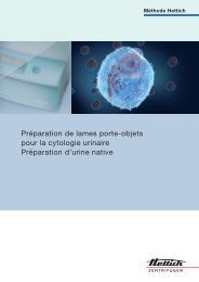
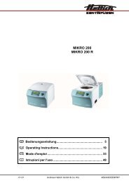
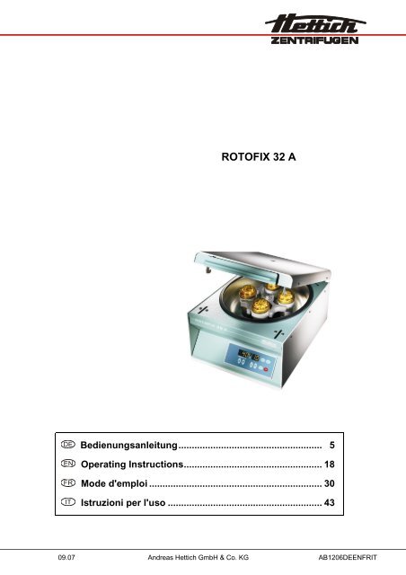
Fig. 1<br />
Fig. 2 <strong>ROTOFIX</strong> <strong>32</strong> A<br />
2/72<br />
IMPULS<br />
RCF<br />
START<br />
STOP<br />
A
EG-Konformitätserklärung<br />
EC Conformity Declaration<br />
Déclaration de conformité CE<br />
Dichiarazione di conformità alle norme CEE<br />
Andreas <strong>Hettich</strong> GmbH & Co. KG • Föhrenstraße 12 • D-785<strong>32</strong> Tuttlingen • Germany<br />
Das bezeichnete Gerät, inklusive Zubehör entspricht den aufgeführten EG-Richtlinien und Normen.<br />
The denoted device, including accessories corresponds to the listed EC guidelines and standards.<br />
L'appareil désigné, y compris les accessoires, correspond aux directives CE et aux normes énumérées.<br />
L'apparecchio designato, compresi gli accessori, è conforme alle direttive CE e alle norme citate.<br />
Geräteart, Type of device, Type d'appareil, Tipo di apparecchio:<br />
Laborzentrifuge mit Zubehör, Laboratory centrifuge with accessories, Centrifugeuse de<br />
laboratoire avec des accessoires, Centrifuga da laboratorio con accessori<br />
Typenbezeichnung, Type designation, Désignation de modèle, Contrassegno tipo:<br />
<strong>ROTOFIX</strong> <strong>32</strong> A<br />
EG-Richtlinien/Normen, EC guidelines/standards, Directives CE/Normes, Direttive/Norme CEE:<br />
73/23/EWG, EN 61010-1, EN 61010-2-020<br />
89/336/EWG + 92/31/EWG + 93/68/EWG, EN 61000-6-1, EN 55011, EN 61000-3-2, EN 61000-3-3<br />
98/37/EG, EN ISO 12100-1, EN ISO 12100-2<br />
98/79/EG<br />
Tuttlingen, 04.09.2007<br />
H. Eberle<br />
3/72
Andreas <strong>Hettich</strong> GmbH & Co. KG<br />
Föhrenstraße 12, D-785<strong>32</strong> Tuttlingen / Germany<br />
Phone +49 (0)7461 / 705-0<br />
Fax +49 (0)7461 / 705-125<br />
info@hettichlab.com, service@hettichlab.com<br />
www.hettichlab.com<br />
© 2006 by Andreas <strong>Hettich</strong> GmbH & Co. KG<br />
All rights reserved. No part of this publication may be reproduced without the written prior permission of the copyright<br />
owner.<br />
Änderungen vorbehalten! , Modifications reserved! , Sous réserve de modifications ! , Con riserva di modifiche!<br />
AB1206DEENFRIT / 09.07<br />
4/72
Inhaltsverzeichnis<br />
1 Bestimmungsgemäße Verwendung........................................................................................................................6<br />
2 Restrisiken ..............................................................................................................................................................6<br />
3 Technische Daten...................................................................................................................................................6<br />
4 Sicherheitshinweise ................................................................................................................................................7<br />
5 Bedeutung der Symbole .........................................................................................................................................8<br />
6 Lieferumfang...........................................................................................................................................................8<br />
7 Auspacken der Zentrifuge.......................................................................................................................................8<br />
8 Inbetriebnahme.......................................................................................................................................................8<br />
9 Deckel öffnen und schließen...................................................................................................................................9<br />
9.1 Deckel öffnen...................................................................................................................................................9<br />
9.2 Deckel schließen .............................................................................................................................................9<br />
10 Ein- und Ausbau des Rotors................................................................................................................................9<br />
11 Beladen des Rotors.............................................................................................................................................9<br />
12 Bedien- und Anzeigeelemente ..........................................................................................................................10<br />
12.1 Symbole des Bedienfeldes.........................................................................................................................10<br />
12.2 Tasten und Einstellmöglichkeiten...............................................................................................................10<br />
13 Bremsstufe einstellen ........................................................................................................................................11<br />
14 Zentrifugierradius einstellen ..............................................................................................................................11<br />
15 Zentrifugation ....................................................................................................................................................11<br />
15.1 Zentrifugation mit Zeitvorwahl ....................................................................................................................12<br />
15.2 Dauerlauf ...................................................................................................................................................12<br />
15.3 Kurzzeitzentrifugation.................................................................................................................................12<br />
15.4 Anzeige der relativen Zentrifugalbeschleunigung (RCF)............................................................................12<br />
16 Relative Zentrifugalbeschleunigung (RCF)........................................................................................................13<br />
17 Zentrifugation von Stoffen mit höherer Dichte ...................................................................................................13<br />
18 Rotor-Erkennung ...............................................................................................................................................13<br />
19 Notentriegelung.................................................................................................................................................13<br />
20 Pflege und Wartung...........................................................................................................................................14<br />
20.1 Zentrifuge...................................................................................................................................................14<br />
20.2 Rotoren und Zubehör.................................................................................................................................14<br />
20.2.1 Tragzapfen..........................................................................................................................................14<br />
20.2.2 Rotoren und Zubehör mit begrenzter Verwendungsdauer ..................................................................14<br />
20.3 Autoklavieren .............................................................................................................................................15<br />
20.4 Zentrifugiergefäße......................................................................................................................................15<br />
21 Störungen..........................................................................................................................................................16<br />
22 Netzeingangssicherungen wechseln .................................................................................................................17<br />
23 Reparaturannahme von Zentrifugen..................................................................................................................17<br />
24 Entsorgung........................................................................................................................................................17<br />
25 Anhang / Appendix ............................................................................................................................................56<br />
25.1 Rotoren und Zubehör / Rotors and accessories.........................................................................................56<br />
DE<br />
5/72
DE<br />
1 Bestimmungsgemäße Verwendung<br />
Bei der vorliegenden Maschine handelt es sich um ein Medizinprodukt (Laborzentrifuge) im Sinne der IVD-Richtline<br />
98/79/EG. Die Zentrifuge dient zum Trennen von Stoffen bzw. Stoffgemischen mit einer Dichte von max. 1,2 kg/dm³.<br />
Darunter fallen auch Stoffe und Stoffgemische menschlichen Ursprungs. Die Zentrifuge ist nur für diesen<br />
Verwendungszweck bestimmt. Eine andere oder darüber hinausgehende Benutzung gilt als nicht<br />
bestimmungsgemäß. Für hieraus entstehende Schäden haftet die Firma Andreas <strong>Hettich</strong> GmbH & Co. KG nicht.<br />
Zur bestimmungsgemäßen Verwendung gehört auch das Beachten aller Hinweise aus der Bedienungsanleitung und<br />
die Einhaltung der Inspektions- und Wartungsarbeiten.<br />
2 Restrisiken<br />
Die Maschine ist nach dem Stand der Technik und den anerkannten sicherheitstechnischen Regeln gebaut. Bei<br />
unsachgemäßer Verwendung und Behandlung können Gefahren für Leib und Leben des Benutzers oder Dritter bzw.<br />
Beeinträchtigungen an der Maschine oder an anderen Sachwerten entstehen. Die Maschine ist nur für die<br />
bestimmungsgemäße Verwendung, und nur in sicherheitstechnisch einwandfreiem Zustand zu benutzen.<br />
Störungen, die die Sicherheit beeinträchtigen können, sind umgehend zu beseitigen.<br />
3 Technische Daten<br />
Hersteller<br />
Andreas <strong>Hettich</strong> GmbH & Co. KG<br />
D-785<strong>32</strong> Tuttlingen<br />
Modell <strong>ROTOFIX</strong> <strong>32</strong> A<br />
Typ 1206 1206-01 1206-02<br />
Netzspannung (± 10%) 208 – 240 V 1∼ 100 – 127 V 1∼<br />
Netzfrequenz 50 – 60 Hz 50 – 60 Hz<br />
Anschlusswert 300 VA 300 VA<br />
Stromaufnahme 1.4 A 3.0 A<br />
Kapazität max. 4 x 100 ml / <strong>32</strong> x 15 ml<br />
zulässige Dichte 1.2 kg/dm 3<br />
Drehzahl (RPM) 6000<br />
Beschleunigung (RCF) 4186<br />
Kinetische Energie 3160 Nm<br />
Prüfpflicht (BGR 261)<br />
Umgebungsbedingungen (EN 61010-1)<br />
nein<br />
− Aufstellungsort nur in Innenräumen<br />
− Höhe bis zu 2000 m über Normal-Null<br />
− Umgebungstemperatur 2°C bis 40°C<br />
− Luftfeuchtigkeit maximale relative Luftfeuchte 80% für Temperaturen bis 31°C, linear<br />
abnehmend bis 50% relativer Luftfeuchte bei 40°C.<br />
− Überspannungskategorie<br />
(IEC 60364-4-443)<br />
ΙΙ<br />
− Verschmutzungsgrad 2<br />
Geräteschutzklasse Ι<br />
nicht für den Einsatz in explosionsgefährdeter Umgebung geeignet.<br />
EMV<br />
− Störaussendung (Funkentstörung) EN 55011,<br />
Gruppe 1, Klasse B<br />
EN 61000-3-2<br />
EN 61000-3-3<br />
6/72<br />
FCC Class B<br />
− Störfestigkeit EN 61000-6-2 ----<br />
Geräuschpegel (rotorabhängig) ≤ 57 dB(A)<br />
Abmessungen<br />
− Breite 366 mm<br />
− Tiefe 430 mm<br />
− Höhe 257 mm<br />
Gewicht 23 kg ca. 27 kg
4 Sicherheitshinweise<br />
Bei Nichteinhaltung dieser Hinweise kann beim Hersteller kein Gewährleistungsanspruch geltend<br />
gemacht werden.<br />
• Vor Inbetriebnahme der Zentrifuge ist die Bedienungsanleitung zu lesen und zu beachten.<br />
Nur Personen, die die Bedienungsanleitung gelesen und verstanden haben, dürfen das Gerät bedienen.<br />
• Neben der Bedienungsanleitung und den verbindlichen Regelungen der Unfallverhütung sind auch die<br />
anerkannten fachtechnischen Regeln für sicherheits- und fachgerechtes Arbeiten zu beachten. Die<br />
Bedienungsanleitung ist um Anweisungen aufgrund bestehender nationaler Vorschriften des Verwenderlandes<br />
zur Unfallverhütung und zum Umweltschutz zu ergänzen.<br />
• Die Zentrifuge ist nach dem Stand der Technik gebaut und betriebssicher.<br />
− Es können aber von ihr Gefahren für den Benutzer oder Dritte ausgehen, wenn sie nicht von geschultem<br />
Personal oder unsachgemäß oder zu nicht bestimmungsgemäßem Gebrauch eingesetzt wird.<br />
• Die Zentrifuge ist so aufzustellen, dass sie standsicher betrieben werden kann.<br />
• Vor Benutzung der Zentrifuge unbedingt den Rotor auf festen Sitz prüfen.<br />
• Während eines Zentrifugationslaufes dürfen sich gemäß IEC 61010-2-020, in einem Sicherheitsbereich von<br />
300 mm um die Zentrifuge herum, keine Personen, Gefahrstoffe und Gegenstände befinden.<br />
• Die Zentrifuge darf während des Betriebs nicht bewegt oder angestoßen werden.<br />
• Im Störungsfall bzw. bei der Notentriegelung nie in den sich drehenden Rotor greifen.<br />
• Um Schäden durch Kondensat zu vermeiden, muss bei Wechsel von einem kalten in einen warmen Raum die<br />
Zentrifuge entweder mindestens 3 Stunden im warmen Raum aufwärmen bevor sie an das Netz angeschlossen<br />
werden darf oder 30 Minuten im kalten Raum warmlaufen.<br />
• Es dürfen nur die vom Hersteller für dieses Gerät zugelassenen Rotoren und das zugelassene Zubehör<br />
verwendet werden (siehe Kapitel "Anhang/Appendix, Rotoren und Zubehör/Rotors and accessories").<br />
• Der Rotor der Zentrifuge darf nur entsprechend dem Kapitel "Beladen des Rotors" beladen werden.<br />
• Bei der Zentrifugation mit maximaler Drehzahl darf die Dichte der Stoffe oder Stoffgemische 1,2 kg/dm 3 nicht<br />
überschreiten.<br />
• Zentrifugationen mit unzulässiger Unwucht sind nicht erlaubt.<br />
• Die Zentrifuge darf nicht in explosionsgefährdeter Umgebung betrieben werden.<br />
• Eine Zentrifugation mit:<br />
− brennbaren oder explosiven Materialien<br />
− Materialien, die chemisch mit hoher Energie miteinander reagieren ist verboten.<br />
• Bei der Zentrifugation von gefährlichen Stoffen bzw. Stoffgemischen, die toxisch, radioaktiv oder mit pathogenen<br />
Mikroorganismen verseucht sind, sind durch den Benutzer geeignete Maßnahmen zu treffen.<br />
Es müssen grundsätzlich Zentrifugiergefäße mit speziellen Schraubverschlüssen für gefährliche Substanzen<br />
verwendet werden. Bei Materialien der Risikogruppe 3 und 4 ist zusätzlich zu den verschließbaren<br />
Zentrifugiergefäßen ein Bio-Sicherheitssystem zu verwenden (siehe Handbuch "Laboratory Biosafety Manual"<br />
der Weltgesundheitsorganisation).<br />
Bei einem Bio-Sicherheitssystem verhindert eine Bioabdichtung (Dichtring) zwischen Gehänge und Deckel das<br />
Austreten von Tröpfchen und Aerosolen.<br />
Wird das Gehänge eines Bio-Sicherheitssystems ohne den Deckel verwendet, muss der Dichtring vom Gehänge<br />
entfernt werden, um eine Beschädigung des Dichtrings während des Zentrifugationslaufes zu vermeiden.<br />
Beschädigte Dichtringe dürfen nicht mehr zum Abdichten des Bio-Sicherheitssystems verwendet werden.<br />
Ohne Verwendung eines Bio-Sicherheitssystems ist eine Zentrifuge im Sinne der Norm EN 61010-2-020 nicht<br />
mikrobiologisch dicht.<br />
Lieferbare Bio-Sicherheitssysteme siehe Kapitel "Anhang/Appendix, Rotoren und Zubehör/Rotors and<br />
accessories". Im Zweifelsfall sind entsprechende Informationen beim Hersteller einzuholen.<br />
• Der Betrieb der Zentrifuge mit stark korrodierenden Stoffen, welche die mechanische Festigkeit von Rotoren,<br />
Gehängen und Zubehörteilen beeinträchtigen können, ist nicht erlaubt.<br />
• Rotoren, Gehänge und Zubehörteile, die starke Korrosionsspuren oder mechanische Schäden aufweisen, oder<br />
deren Verwendungsdauer abgelaufen ist, dürfen nicht mehr verwendet werden.<br />
• Reparaturen dürfen nur von einer vom Hersteller autorisierten Person ausgeführt werden.<br />
• Es dürfen nur Originalersatzteile und zugelassenes Originalzubehör der Firma Andreas <strong>Hettich</strong> GmbH & Co. KG<br />
verwendet werden.<br />
• Es gelten die folgenden Sicherheitsbestimmungen:<br />
IEC 61010-1 und IEC 61010-2-020 sowie deren nationalen Abweichungen.<br />
• Die Sicherheit und Zuverlässigkeit der Zentrifuge ist nur dann gewährleistet, wenn:<br />
− die Zentrifuge nach der Bedienungsanleitung betrieben wird.<br />
− die elektrische Installation, am Aufstellungsort der Zentrifuge, den Anforderungen von IEC Festlegungen<br />
entspricht.<br />
− vorgeschriebene Prüfungen nach BGV A1, BGR 261 durch einen Sachkundigen durchgeführt werden.<br />
DE<br />
7/72
DE<br />
5 Bedeutung der Symbole<br />
8/72<br />
Symbol an der Maschine:<br />
Achtung, allgemeine Gefahrenstelle.<br />
Vor Benutzung der Zentrifuge unbedingt die Bedienungsanleitung lesen und die sicherheitsrelevanten<br />
Hinweise beachten!<br />
Symbol in der Bedienungsanleitung:<br />
Achtung, allgemeine Gefahrenstelle.<br />
Dieses Symbol kennzeichnet sicherheitsrelevante Hinweise und deutet auf mögliche gefährliche<br />
Situationen hin.<br />
Das Nichtbeachten dieser Hinweise kann zu Sach- und Personenschäden führen.<br />
Symbol in der Bedienungsanleitung:<br />
Dieses Symbol deutet auf wichtige Sachverhalte hin.<br />
Symbol an der Maschine und in der Bedienungsanleitung:<br />
Symbol für die getrennte Sammlung von Elektro- und Elektronikgeräten, gemäß der Richtlinie<br />
2002/96/EG (WEEE). Das Gerät gehört zur Gruppe 8 (Medizinische Geräte).<br />
Verwendung in den Ländern der Europäischen Union sowie in Norwegen und der Schweiz.<br />
6 Lieferumfang<br />
Folgendes Zubehör wird mit der Zentrifuge geliefert:<br />
1 Anschlusskabel<br />
2 Sicherungen (Typ 1206-02: 3 Sicherungen)<br />
1 Schmierfett für Tragzapfen<br />
1 Sechskantstiftschlüssel<br />
1 Entriegelungsstift<br />
1 Hinweisblatt Transportsicherung<br />
1 Bedienungsanleitung<br />
Rotor(en) und das entsprechende Zubehör werden je nach Bestellung mitgeliefert.<br />
7 Auspacken der Zentrifuge<br />
• Den Karton nach oben abheben und die Polsterung entfernen.<br />
•<br />
Nicht an der Griffleiste des Deckels anheben.<br />
Das Gewicht der Zentrifuge beachten, siehe Kapitel "Technische Daten".<br />
Die Zentrifuge, mit der angemessenen Anzahl von Helfern, an beiden Seiten anheben und auf den Labortisch<br />
stellen.<br />
8 Inbetriebnahme<br />
• Gemäß der Laborgerätenorm IEC 61010-2-020 muss in der Gebäudeinstallation ein Notausschalter zur<br />
Trennung der Netzversorgung im Fehlerfall angebracht sein.<br />
Dieser Schalter muss abseits der Zentrifuge angebracht sein, vorzugsweise außerhalb des Raumes, in dem sich<br />
die Zentrifuge befindet, oder neben dem Ausgang dieses Raumes.<br />
• Die Transportsicherung am Gehäuseboden entfernen, siehe Hinweisblatt "Transportsicherung".<br />
• Die Zentrifuge an einem geeigneten Platz standsicher aufstellen und nivellieren. Bei der Aufstellung ist der<br />
geforderte Sicherheitsbereich gemäß IEC 61010-2-020, von 300 mm um die Zentrifuge herum, einzuhalten.<br />
Während eines Zentrifugationslaufes dürfen sich gemäß IEC 61010-2-020, in einem Sicherheitsbereich<br />
von 300 mm um die Zentrifuge herum, keine Personen, Gefahrstoffe und Gegenstände<br />
befinden.<br />
• Lüftungsöffnungen dürfen nicht zugestellt werden.<br />
Es muss ein Lüftungsabstand von 300 mm um die Lüftungsschlitze oder Lüftungsöffnungen eingehalten werden.<br />
• Prüfen ob die Netzspannung mit der Angabe auf dem Typenschild übereinstimmt.<br />
• Die Zentrifuge mit dem Anschlusskabel an eine genormte Netzsteckdose anschließen. Anschlusswert siehe<br />
Kapitel "Technische Daten".<br />
• Den Netzschalter einschalten. Schalterstellung "Ι".<br />
Die zuletzt benutzten Zentrifugierdaten werden angezeigt.<br />
• Den Deckel öffnen.
9 Deckel öffnen und schließen<br />
9.1 Deckel öffnen<br />
Der Deckel lässt sich nur öffnen, wenn die Zentrifuge eingeschaltet ist und der Rotor stillsteht.<br />
Sollte dies nicht möglich sein, siehe Kapitel "Notentriegelung".<br />
• Die Griffleiste am Deckel nach oben schwenken. In der Rotationsanzeige leuchtet das Symbol " " (Deckel<br />
geöffnet).<br />
• Den Deckel öffnen.<br />
9.2 Deckel schließen<br />
Den Deckel nicht zuschlagen.<br />
• Den Deckel auflegen und die Griffleiste am Deckel nach unten schwenken. In der Rotationsanzeige leuchtet<br />
das Symbol " " (Deckel geschlossen).<br />
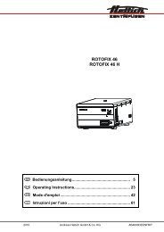
10 Ein- und Ausbau des Rotors<br />
A<br />
C<br />
D<br />
11 Beladen des Rotors<br />
B<br />
• Die Motorwelle (C) und die Bohrung des Rotors (A) reinigen und anschließend die<br />
Motorwelle leicht einfetten. Schmutzpartikel zwischen der Motorwelle und dem Rotor<br />
verhindern einen einwandfreien Sitz des Rotors und verursachen einen unruhigen Lauf.<br />
• Den Rotor vertikal auf die Motorwelle aufsetzen. Der Mitnehmer der Motorwelle (D)<br />
muss sich in der Nut des Rotors (B) befinden. Auf dem Rotor ist die Ausrichtung der Nut<br />
gekennzeichnet.<br />
• Die Spannmutter des Rotors mit dem mitgelieferten Schlüssel durch Drehen im<br />
Uhrzeigersinn anziehen.<br />
• Den Rotor auf festen Sitz prüfen.<br />
• Lösen des Rotors: Die Spannmutter durch Drehen entgegen dem Uhrzeigersinn lösen<br />
und bis zum Abhebe-Druckpunkt drehen. Nach Überwindung des Abhebe-Druckpunkts<br />
löst sich der Rotor vom Konus der Motorwelle. Die Spannmutter drehen, bis sich der<br />
Rotor von der Motorwelle abheben lässt.<br />
Standard-Zentrifugiergefäße aus Glas sind belastbar bis RZB 4000 (DIN 58970 Teil 2).<br />
• Den Rotor auf festen Sitz prüfen.<br />
• Bei Ausschwingrotoren müssen alle Plätze des Rotors mit gleichen Gehängen besetzt sein. Bestimmte<br />
Gehänge sind mit der Nummer des Rotorplatzes gekennzeichnet. Diese Gehänge dürfen nur in den<br />
entsprechenden Platz des Rotors eingesetzt werden.<br />
• Die Rotoren und Gehänge dürfen nur symmetrisch beladen werden. Zugelassene Kombinationen siehe Kapitel<br />
"Anhang/Appendix, Rotoren und Zubehör/Rotors and accessories".<br />
Bei Winkelrotoren müssen alle möglichen Plätze des Rotors beladen werden, siehe Kapitel "Anhang/Appendix,<br />
Rotoren und Zubehör/Rotors and accessories".<br />
• Auf bestimmten Gehängen ist das Gewicht der maximalen Beladung und das maximale Gewicht des komplett<br />
bestückten Gehänges angegeben. Diese Gewichte dürfen nicht überschritten werden. Die Gewichtsangabe der<br />
maximalen Beladung umfasst das Gesamtgewicht von Reduzierung, Gestell, Zentrifugiergefäß und Inhalt.<br />
• Bei Behältern mit Gummieinlagen muss sich unter den Zentrifugiergefäßen immer die gleiche Anzahl von<br />
Gummieinlagen befinden.<br />
• Die Zentrifugiergefäße immer außerhalb der Zentrifuge befüllen.<br />
• Es darf beim Füllen und beim Ausschwingen der Gehänge keine Flüssigkeit in den Schleuderraum gelangen.<br />
• Die vom Hersteller angegebene maximale Füllmenge der Zentrifugiergefäße darf nicht überschritten werden.<br />
• Um die Gewichtsunterschiede innerhalb der Zentrifugiergefäße möglichst gering zu halten, ist auf eine<br />
gleichmäßige Füllhöhe in den Gefäßen zu achten.<br />
DE<br />
9/72
DE<br />
12 Bedien- und Anzeigeelemente<br />
Siehe Abbildung auf Seite 2.<br />
Fig. 2: Anzeige- und Bedienfeld<br />
12.1 Symbole des Bedienfeldes<br />
10/72<br />
Rotationsanzeige. Die Rotationsanzeige leuchtet rotierend gegen den Uhrzeigersinn auf, solange sich der<br />
Rotor dreht.<br />
Bei Stillstand des Rotors wird in der Rotationsanzeige durch Symbole der Zustand des Deckels angezeigt:<br />
Symbol : Deckel geöffnet<br />
Symbol : Deckel geschlossen<br />
Bedienfehler und auftretende Störungen werden im Display angezeigt (siehe Kapitel "Störungen").<br />
12.2 Tasten und Einstellmöglichkeiten<br />
RPM/RCF x 100<br />
t<br />
START<br />
STOP<br />
RCF<br />
IMPULS<br />
• Drehzahl<br />
Einstellbar ist ein Zahlenwert von 500 RPM bis zur maximalen Drehzahl des Rotors. Maximale<br />
Drehzahl des Rotors siehe Kapitel "Anhang/Appendix, Rotoren und Zubehör/Rotors and<br />
accessories“. Einstellbar in 100er Schritten (RPM = angezeigter Wert x 100).<br />
Bei Gedrückthalten der Taste oder ändert sich der Wert mit zunehmender Geschwindigkeit.<br />
• Die Bremsstufe und den Zentrifugierradius anzeigen.<br />
• Laufzeit<br />
- Einstellbar von 1 - 99 Minuten, in 1 Minuten-Schritten<br />
- Dauerlauf "--"<br />
• Zentrifugierradius. Eingabe in Zentimeter. Einstellbar von 5 - 16 Zentimeter, in 1 Zentimeter-<br />
Schritten. Zentrifugierradius siehe Kapitel "Anhang/Appendix, Rotoren und Zubehör/Rotors and<br />
accessories".<br />
• Bremsstufen 0 oder 1. Stufe 1 = kurze Auslaufzeit, Stufe 0 = lange Auslaufzeit.<br />
Bei Gedrückthalten der Taste oder ändert sich der Wert mit zunehmender Geschwindigkeit.<br />
• Zentrifugationslauf starten.<br />
• Zentrifugationslauf beenden.<br />
Der Rotor läuft mit vorgewählter Bremsstufe aus.<br />
• Die Bremsstufe und den Zentrifugierradius speichern.<br />
• Anzeige der relativen Zentrifugalbeschleunigung (RCF).<br />
Die Anzeige der relativen Zentrifugalbeschleunigung (RCF) erfolgt, solange die Taste RCF<br />
gedrückt gehalten wird.<br />
• Kurzzeitzentrifugation.<br />
Der Zentrifugationslauf erfolgt, solange die Taste IMPULS gedrückt gehalten wird.<br />
• Die Bremsstufe und den Zentrifugierradius anzeigen.
13 Bremsstufe einstellen<br />
• Den Netzschalter ausschalten.<br />
• Die Taste unterhalb der Drehzahl-Anzeige und die Taste IMPULS gleichzeitig gedrückt halten.<br />
• Den Netzschalter einschalten und die Tasten wieder loslassen.<br />
• Die Taste unterhalb der Drehzahl-Anzeige gegebenenfalls so oft drücken, bis folgende Anzeige erscheint:<br />
IMPULS<br />
RCF<br />
START<br />
STOP<br />
In der Drehzahl-Anzeige wird die werksseitig eingestellte Maschinenversion (z.B. 7) und in der Zeit-Anzeige die<br />
eingestellte Bremsstufe angezeigt.<br />
• Mit den Tasten unterhalb der Zeit-Anzeige die gewünschte Bremsstufe einstellen.<br />
Stufe 1 = kurze Auslaufzeit, Stufe 0 = lange Auslaufzeit.<br />
Auslaufzeiten siehe Kapitel "Anhang/Appendix, Rotoren und Zubehör/Rotors and accessories".<br />
• Die Taste STOP drücken um die Einstellung zu speichern.<br />
14 Zentrifugierradius einstellen<br />
Der Zentrifugierradius muss in Zentimeter eingegeben werden.<br />
• Den Netzschalter ausschalten.<br />
• Die Taste unterhalb der Drehzahl-Anzeige und die Taste IMPULS gleichzeitig gedrückt halten.<br />
• Den Netzschalter einschalten und die Tasten wieder loslassen.<br />
• Die Taste unterhalb der Drehzahl-Anzeige so of drücken, bis folgende Anzeige erscheint:<br />
IMPULS<br />
RCF<br />
START<br />
STOP<br />
In der Drehzahl-Anzeige wird der eingestellte Zentrifugierradius angezeigt.<br />
• Mit den Tasten unterhalb der Zeit-Anzeige den gewünschten Zentrifugierradius einstellen.<br />
Zentrifugierradius siehe Kapitel "Anhang/Appendix, Rotoren und Zubehör/Rotors and accessories".<br />
• Die Taste STOP drücken um die Einstellung zu speichern.<br />
15 Zentrifugation<br />
Während eines Zentrifugationslaufes dürfen sich gemäß IEC 61010-2-020, in einem Sicherheitsbereich von<br />
300 mm um die Zentrifuge herum, keine Personen, Gefahrstoffe und Gegenstände befinden.<br />
Wird der zulässige Gewichtsunterschied innerhalb der Beladung des Rotors überschritten, schaltet der Antrieb<br />
während des Anlaufs ab, und Fehler -3- wird angezeigt (siehe Kapitel "Störungen").<br />
Ein Zentrifugationslauf kann jederzeit durch Drücken der Taste STOP abgebrochen werden.<br />
Die Zeit und die Drehzahl können während des Zentrifugationslaufes, mit den Tasten , geändert werden.<br />
Bei Gedrückthalten der Taste oder ändert sich der Wert mit zunehmender Geschwindigkeit.<br />
Nach einem Zentrifugationslauf blinkt die Anzeige bis der Deckel geöffnet, oder eine Taste gedrückt wird.<br />
Blinkt in der Rotationsanzeige abwechselnd das Symbol " " (Deckel geschlossen) und " " (Deckel<br />
geöffnet), so ist eine weitere Bedienung der Zentrifuge erst nach einmaligem Öffnen des Deckels möglich.<br />
Wird rot xx angezeigt, so hat kein Zentrifugationslauf stattgefunden, weil zuvor der Rotor gewechselt wurde,<br />
siehe Kapitel "Rotor-Erkennung".<br />
• Den Netzschalter einschalten (Schalterstellung "Ι").<br />
• Den Rotor beladen und den Zentrifugendeckel schließen.<br />
IMPULS<br />
RCF<br />
START<br />
STOP<br />
DE<br />
11/72
DE<br />
15.1 Zentrifugation mit Zeitvorwahl<br />
• Mit den Tasten unterhalb der Drehzahl-Anzeige die gewünschte Drehzahl einstellen.<br />
• Mit den Tasten unterhalb der Zeit-Anzeige die gewünschte Zeit einstellen.<br />
• Die Taste START drücken. Die Rotationsanzeige erfolgt solange sich der Rotor dreht.<br />
12/72<br />
Die Zeit wird in Minuten angezeigt. Die letzte Minute wird in Sekunden heruntergezählt.<br />
Wird die Zeit in Minuten angezeigt, blinkt neben der Zahl ein Punkt.<br />
• Nach Ablauf der Zeit oder bei Abbruch des Zentrifugationslaufes durch Drücken der Taste STOP , erfolgt der<br />
Auslauf des Rotors mit der eingestellten Bremsstufe.<br />
Während des Zentrifugationslaufes werden die Drehzahl des Rotors oder der daraus resultierende RCF-Wert, und<br />
die verbleibende Zeit angezeigt.<br />
15.2 Dauerlauf<br />
• Mit den Tasten unterhalb der Drehzahl-Anzeige die gewünschte Drehzahl einstellen.<br />
• Mit der Taste unterhalb der Zeit-Anzeige die Zeit auf Null stellen. Es wird "--" wird angezeigt.<br />
• Die Taste START drücken. Die Rotationsanzeige<br />
bei 0.<br />
erfolgt solange sich der Rotor dreht. Die Zeitzählung beginnt<br />
Die erste Minute wird in Sekunden hochgezählt, danach wird die Zeit in Minuten angezeigt.<br />
Wird die Zeit in Minuten angezeigt, blinkt neben der Zahl ein Punkt.<br />
• Die Taste STOP drücken um den Zentrifugationslauf zu beenden. Der Auslauf des Rotors erfolgt mit der<br />
eingestellten Bremsstufe.<br />
Während des Zentrifugationslaufes werden die Drehzahl des Rotors oder der daraus resultierende RCF-Wert, und<br />
die gelaufene Zeit angezeigt.<br />
15.3 Kurzzeitzentrifugation<br />
• Mit den Tasten unterhalb der Drehzahl-Anzeige die gewünschte Drehzahl einstellen.<br />
• Die Taste IMPULS gedrückt halten. Die Rotationsanzeige<br />
beginnt bei 0.<br />
erfolgt solange sich der Rotor dreht. Die Zeitzählung<br />
Die erste Minute wird in Sekunden hochgezählt, danach wird die Zeit in Minuten angezeigt.<br />
Wird die Zeit in Minuten angezeigt, blinkt neben der Zahl ein Punkt.<br />
• Die Taste IMPULS wieder loslassen um den Zentrifugationslauf zu beenden. Der Auslauf des Rotors erfolgt mit der<br />
eingestellten Bremsstufe.<br />
Während des Zentrifugationslaufes werden die Drehzahl des Rotors und die gelaufene Zeit angezeigt.<br />
15.4 Anzeige der relativen Zentrifugalbeschleunigung (RCF)<br />
Während des Zentrifugationslaufes kann die relative Zentrifugalbeschleunigung (RCF) angezeigt werden.<br />
Wird mit der relativen Zentrifugalbeschleunigung (RCF) gearbeitet, ist die Eingabe des Zentrifugierradius<br />
notwendig.<br />
• Während des Zentrifugationslaufes die Taste RCF gedrückt halten.<br />
Die relative Zentrifugalbeschleunigung (RCF) erscheint in der Drehzahl-Anzeige (RCF = angezeigter Wert x<br />
100).<br />
• Die Taste RCF wieder loslassen. Es wird wieder die Drehzahl angezeigt.
16 Relative Zentrifugalbeschleunigung (RCF)<br />
Die relative Zentrifugalbeschleunigung (RCF) wird als Vielfaches der Erdbeschleunigung (g) angegeben. Sie ist ein<br />
einheitsfreier Zahlenwert und dient zum Vergleich der Trenn- und Sedimentationsleistung.<br />
Die Berechnung erfolgt nach der Formel:<br />
RCF<br />
2<br />
⎛ RPM ⎞<br />
⎜ × r × 1,118<br />
1000<br />
⇒ RPM =<br />
RCF<br />
× 1000<br />
r × 1,118<br />
= ⎟<br />
⎝ ⎠<br />
RCF = Relative Zentrifugalbeschleunigung<br />
RPM = Drehzahl<br />
r = Zentrifugierradius in mm = Abstand von der Mitte der Drehachse bis zum Zentrifugiergefäßboden.<br />
Zentrifugierradius siehe Kapitel "Anhang/Appendix, Rotoren und Zubehör/<br />
Rotors and accessories".<br />
Die relative Zentrifugalbeschleunigung (RCF) ist abhängig von der Drehzahl und dem Zentrifugierradius.<br />
17 Zentrifugation von Stoffen mit höherer Dichte<br />
Die Rotoren sind so konstruiert, dass sie bei angegebener Nenndrehzahl Stoffe mit einer durchschnittlichen<br />
homogenen Dichte von max. 1,2 kg/dm 3 zentrifugieren können. Stoffe mit einer höheren Dichte müssen mit<br />
reduzierter Drehzahl zentrifugiert werden.<br />
Die erlaubte Drehzahl lässt sich nach folgender Formel berechnen:<br />
1,2<br />
Reduzierte Drehzahl (nred<br />
) =<br />
× Nenndrehzahl<br />
höhere Dichte<br />
z.B.: RPM 4000, Dichte 1,6 kg/dm 3<br />
1,2<br />
nred = × 4000 = 3464 RPM<br />
1,6<br />
Bei eventuellen Unklarheiten ist Auskunft beim Hersteller einzuholen.<br />
18 Rotor-Erkennung<br />
Nach jedem Start eines Zentrifugationslaufes wird der eingesetzte Rotor erkannt.<br />
Nach einem Rotorwechsel schaltet der Antrieb ab und der Rotorcode (rot xx) des Rotors wird angezeigt.<br />
• Die Taste START drücken. Die zuletzt benutzten Zentrifugierdaten werden angezeigt.<br />
Eine weitere Bedienung der Zentrifuge ist erst nach einmaligem Öffnen des Deckels möglich.<br />
Wenn nach einem Rotorwechsel die maximale Drehzahl des Rotors kleiner als die eingestellte Drehzahl ist,<br />
wird die Drehzahl auf die maximale Drehzahl des Rotors begrenzt.<br />
19 Notentriegelung<br />
Bei einem Stromausfall kann der Deckel nicht geöffnet werden. Es muss eine Notentriegelung von Hand<br />
durchgeführt werden.<br />
Zur Notentriegelung die Zentrifuge vom Netz trennen.<br />
Den Deckel nur bei Stillstand des Rotors öffnen.<br />
Zur Notentriegelung darf nur der, mitgelieferte Entriegelungsstift aus Kunststoff verwendet werden.<br />
Siehe Abbildung auf Seite 2.<br />
• Den Netzschalter ausschalten (Schalterstellung "0").<br />
• Durch das Fenster im Deckel schauen, um sich zu vergewissern, dass der Rotor stillsteht.<br />
• Den Entriegelungsstift (siehe Lieferumfang) waagerecht in die Bohrung einführen (Fig. 1, A). Den<br />
Entriegelungsstift so weit hineinschieben, bis sich beim nach unten Drücken des Stiftes die Griffleiste<br />
nach oben schwenken lässt.<br />
• Den Deckel öffnen.<br />
DE<br />
13/72
DE<br />
20 Pflege und Wartung<br />
14/72<br />
Vor der Reinigung den Netzstecker ziehen.<br />
Bevor ein anderes als das vom Hersteller empfohlene Reinigungs- oder Dekontaminationsverfahren<br />
angewandt wird, hat sich der Benutzer beim Hersteller zu vergewissern, dass das vorgesehene Verfahren<br />
das Gerät nicht schädigt.<br />
• Es sind Reinigungs- oder Desinfektionsmittel zu verwenden, die im pH-Bereich 5 - 8 liegen. Alkalische<br />
Reinigungsmittel mit einem pH-Wert > 8 sind zu vermeiden.<br />
• Um Korrosionserscheinungen durch Reinigungs- oder Desinfektionsmittel zu vermeiden sind die speziellen<br />
Anwendungshinweise vom Hersteller des Reinigungs- oder Desinfektionsmittels unbedingt zu beachten.<br />
20.1 Zentrifuge<br />
• Das Gehäuse der Zentrifuge und den Schleuderraum regelmäßig säubern und bei Bedarf mit Seife oder einem<br />
milden Reinigungsmittel und einem feuchten Tuch reinigen. Dies dient zum einen der Hygiene und es verhindert<br />
Korrosion durch anhaftende Verunreinigungen.<br />
• Bei Bildung von Kondenswasser den Schleuderraum, durch Auswischen mit einem saugfähigen Tuch, trocknen.<br />
• Gelangt infektiöses Material in den Schleuderraum, so ist dieser umgehend zu desinfizieren. Zur Flächen-<br />
Desinfektion empfehlen wir Bacillol® Plus von der Firma Bode Chemie Hamburg oder Biocidal ZF TM von der<br />
Firma WAK-Chemie Medical GmbH Steinbach.<br />
• Die Gummidichtung des Schleuderraums nach jeder Reinigung leicht einfetten.<br />
20.2 Rotoren und Zubehör<br />
• Um einer Korrosion und Materialveränderungen vorzubeugen müssen die Rotoren und die Zubehörteile<br />
regelmäßig mit Seife oder einem milden Reinigungsmittel und einem feuchten Tuch gereinigt werden. Die<br />
Reinigung wird mindestens einmal wöchentlich, noch besser nach jedem Gebrauch empfohlen.<br />
• Sind die Rotoren oder die Zubehörteile durch pathogenes oder radioaktives Material verunreinigt, so muss eine<br />
geeignete Reinigung durchgeführt werden. Zur Desinfektion empfehlen wir Helipur ® H plus N von der Firma B.<br />
Braun Melsungen. Zum Entfernen von radioaktivem Material empfehlen wir decon neutracon ® von der Firma<br />
Decon Laboratories Limited.<br />
• Die Rotoren und Zubehörteile müssen unmittelbar nach der Reinigung getrocknet werden.<br />
• Winkelrotoren, Behälter und Gehänge aus Aluminium sind nach dem Trocknen mit säurefreiem Fett z.B.<br />
Vaseline leicht einzufetten.<br />
• Bei aerosoldichten Rotoren und Bio-Sicherheitssystemen (siehe Kapitel "Anhang/Appendix, Rotoren und<br />
Zubehör/Rotors and accessories") sind die Dichtungsringe regelmäßig (wöchentlich) zu prüfen und zu reinigen.<br />
Bei Anzeichen von Rissbildung, Versprödung oder Abnutzung ist der Dichtungsring sofort auszutauschen. Um<br />
ein Verdrehen des Dichtungsringes während dem Öffnen und Schließen des Deckels zu vermeiden, muss der<br />
Dichtungsring mit säurefreiem Fett z.B. Vaseline leicht eingefettet werden.<br />
• Um Korrosion infolge Feuchtigkeit zwischen Rotor und Motorwelle zu verhindern, sollte der Rotor mindestens<br />
einmal im Monat ausgebaut, gereinigt und die Motorwelle leicht gefettet werden.<br />
• Die Rotoren und die Zubehörteile sind monatlich auf Korrosionsschäden zu überprüfen.<br />
Rotoren und Zubehör dürfen bei Anzeichen von Verschleiß oder Korrosion nicht mehr verwendet werden.<br />
• Den Rotor wöchentlich auf festen Sitz prüfen.<br />
20.2.1 Tragzapfen<br />
Bei Ausschwingrotoren müssen die Tragzapfen regelmäßig gefettet werden (<strong>Hettich</strong>-Schmierfett Nr. 4051), um ein<br />
gleichmäßiges Ausschwingen der Gehänge zu gewährleisten.<br />
20.2.2 Rotoren und Zubehör mit begrenzter Verwendungsdauer<br />
Die Verwendung von bestimmten Rotoren, Gehängen und Zubehörteilen ist zeitlich begrenzt.<br />
Diese sind mit dem Ablaufdatum gekennzeichnet, z.B.: "einsetzbar bis Ende: / usable until end of: ΙV. Quartal 2011".<br />
Die Rotoren, Gehänge und Zubehörteile dürfen aus Sicherheitsgründen nicht mehr verwendet werden,<br />
wenn das darauf gekennzeichnete Ablaufdatum erreicht ist.
20.3 Autoklavieren<br />
Ausschwingrotoren, Winkelrotoren aus Aluminium, Gehänge aus Metall, Deckel mit Bioabdichtung sowie Gestelle<br />
und Reduzierungen können bei 121°C / 250°F (20 min) autoklaviert werden.<br />
Im Zweifelsfall muss beim Hersteller nachgefragt werden.<br />
Die Deckel der Rotoren und Behälter müssen vor dem Autoklavieren abgenommen werden.<br />
Das Autoklavieren beschleunigt den Alterungsprozess von Kunststoffen. Außerdem kann es bei<br />
Kunststoffen Farbveränderungen verursachen.<br />
Wir empfehlen nach dem Autoklavieren die Dichtungsringe von aerosoldichten Rotoren und Bio-<br />
Sicherheitssystemen auszutauschen.<br />
20.4 Zentrifugiergefäße<br />
• Bei Undichtigkeit oder nach dem Bruch von Zentrifugiergefäßen, sind zerbrochene Gefäßteile, Glassplitter und<br />
ausgelaufenes Zentrifugiergut vollständig zu entfernen.<br />
• Die Gummieinlagen sowie die Kunststoff-Hülsen der Rotoren sind nach einem Glasbruch zu ersetzen.<br />
Verbleibende Glassplitter verursachen weiteren Glasbruch !<br />
• Handelt es sich um infektiöses Material so ist umgehend eine Desinfektion durchzuführen.<br />
DE<br />
15/72
DE<br />
21 Störungen<br />
Lässt sich der Fehler laut Störungstabelle nicht beheben, so ist der Kundendienst zu benachrichtigen.<br />
Bitte den Zentrifugentyp und die Werknummer angeben. Beide Werte sind auf dem Typenschild der Zentrifuge<br />
ersichtlich.<br />
16/72<br />
Einen NETZ-RESET durchführen:<br />
− Den Netzschalter ausschalten (Schalterstellung "0").<br />
− Mindestens 10 Sekunden lang warten und anschließend den Netzschalter wieder einschalten<br />
(Schalterstellung "Ι").<br />
Störung Anzeige Fehlerursache Beseitigung<br />
keine Anzeige --- Keine Spannung.<br />
Netzeingangssicherungen defekt.<br />
Sicherung des Transformators defekt (nur<br />
bei Typ 1206-02)<br />
Tachofehler - 1 - Ausfall der Drehzahlimpulse,<br />
ungebremster Auslauf<br />
− Versorgungsspannung überprüfen.<br />
− Netzeingangssicherungen überprüfen,<br />
siehe Kapitel "Netzeingangssicherungen<br />
wechseln".<br />
− Sicherung des Transformators<br />
überprüfen, siehe Kapitel<br />
"Sicherung des Transformators<br />
wechseln" (nur bei Typ 1206-02).<br />
− Netzschalter EIN.<br />
− Der Deckel lässt sich aus<br />
Sicherheitsgründen erst nach ca.<br />
120 Sekunden öffnen.<br />
− Nach Ablauf dieser Zeit einen<br />
"NETZ-RESET" durchführen.<br />
− Nach Stillstand Deckel öffnen und<br />
Taste START betätigen.<br />
− Deckel nach Rotor-Stillstand öffnen.<br />
− Unwucht beseitigen.<br />
.<br />
NETZ-RESET - 2 - Ausfall der Netzversorgung während eines<br />
Laufes gebremster Auslauf.<br />
Unwucht - 3 - Unwucht an der Motorachse durch<br />
Gewichtsdifferenzen in der<br />
Rotorbestückung.<br />
Kommunikation - 4 - Fehler im Steuerteil oder Leistungsteil − Nach Stillstand des Rotors einen<br />
Ungebremster Auslauf<br />
NETZ-RESET durchführen.<br />
Überlast - 5 - Motor oder Motoransteuerung defekt. − Nach Stillstand des Rotors einen<br />
NETZ-RESET durchführen.<br />
Überspannung<br />
- 6 - Netzspannung außerhalb der Toleranzen − Nach Stillstand des Rotors einen<br />
Unterspannung - 8 - (siehe Technische Daten)<br />
NETZ-RESET durchführen.<br />
Ungebremster Auslauf.<br />
− Netzspannung kontrollieren.<br />
Überdrehzahl - 7 - Fehler im Leistungsteil,<br />
− Nach Stillstand des Rotors einen<br />
ungebremster Auslauf.<br />
NETZ-RESET durchführen.<br />
Übertemperatur - 9 - Übertemperaturschalter im Motor hat − Nach Rotor-Stillstand Deckel durch<br />
ausgelöst.<br />
Notentriegelung öffnen (siehe<br />
Ungebremster Auslauf<br />
Kapitel Notentriegelung).<br />
− Motor abkühlen lassen.<br />
Version Error<br />
Keine<br />
Anzeige<br />
im<br />
Drehzahlfeld,<br />
im<br />
Zeitfeld<br />
steht eine<br />
Ziffer.<br />
Falsche Maschinenversion eingestellt,<br />
Steuerteil springt in das Einstell-Menü.<br />
−<br />
−<br />
Mit Pfeiltaste oder die Ziffer 4<br />
im Zeitfeld einstellen und mit<br />
bestätigen.<br />
Einen NETZ-RESET durchführen.<br />
Controller-Watchdog - C - Fehler in Steuerteil ungebremster Auslauf. − Nach Stillstand des Rotors einen<br />
NETZ-RESET durchführen.<br />
Deckelfehler - d - Ungebremster Auslauf − Nach Stillstand des Rotors einen<br />
NETZ-RESET durchführen.<br />
Kurzschluss - E - Kurzschluss in Steuerteil / Leistungsteil. − Nach Stillstand des Rotors einen<br />
NETZ-RESET durchführen.<br />
Kein Rotorcode - F - Keine Rotorerkennung beim Start. Kein − Nach Stillstand des Rotors einen<br />
Rotor eingesetzt oder defekter Tacho. NETZ-RESET durchführen.<br />
Neuer Rotor erkannt rot... siehe Kapitel Rotorerkennung − START Taste betätigen.
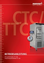
22 Netzeingangssicherungen wechseln<br />
A B<br />
Den Netzschalter ausschalten und die Zentrifuge vom Netz trennen!<br />
Der Sicherungshalter (A) mit den Netzeingangssicherungen befindet sich neben dem<br />
Netzschalter.<br />
• Das Anschlusskabel aus dem Gerätestecker ziehen.<br />
• Den Schnappverschluss (B) gegen den Sicherungshalter (A) drücken und diesen<br />
herausziehen.<br />
• Defekte Netzeingangssicherungen austauschen.<br />
Nur Sicherungen mit dem, für den Typ, festgelegten Nennwert<br />
verwenden, siehe nachfolgende Tabelle.<br />
• Den Sicherungshalter wieder hineinschieben bis der Schnappverschluss<br />
einrastet.<br />
• Die Zentrifuge wieder ans Netz anschließen.<br />
Modell Typ Sicherung Best.-Nr.<br />
<strong>ROTOFIX</strong> <strong>32</strong> A 1206 T 3,15 AH/250V E997<br />
<strong>ROTOFIX</strong> <strong>32</strong> A 1206-01 T 5 AH/250V E914<br />
<strong>ROTOFIX</strong> <strong>32</strong> A 1206-02 T 6,3 AH/250V 2266<br />
23 Reparaturannahme von Zentrifugen<br />
Wird die Zentrifuge zur Reparatur an den Hersteller zurückgesandt, so muss diese, zum Schutz von Personen,<br />
Umwelt und Material, vor dem Versand dekontaminiert und gereinigt werden.<br />
Eine Annahme von kontaminierten Zentrifugen behalten wir uns vor.<br />
Anfallende Kosten für Reinigungs- und Desinfektionsmaßnahmen werden dem Kunden in Rechnung gestellt.<br />
Wir bitten dafür um Ihr Verständnis.<br />
24 Entsorgung<br />
Bei der Entsorgung des Geräts sind die jeweiligen gesetzlichen Vorschriften zu beachten.<br />
Gemäß der Richtlinie 2002/96/EG (WEEE) dürfen alle nach dem 13.08.2005 gelieferten Geräte nicht mehr mit dem<br />
Hausmüll entsorgt werden. Das Gerät gehört zur Gruppe 8 (Medizinische Geräte) und ist in den Business-to-<br />
Business-Bereich eingeordnet.<br />
Mit dem Symbol des durchgestrichenen Abfalleimers wird darauf hingewiesen, dass das Gerät nicht mit<br />
dem Hausmüll entsorgt werden darf.<br />
Die Entsorgungsvorschriften der einzelnen EU-Länder können unterschiedlich sein. Im Bedarfsfall<br />
wenden Sie sich bitte an Ihren Lieferanten.<br />
DE<br />
17/72
EN<br />
Contents<br />
1 Use according to specification ..............................................................................................................................19<br />
2 Residual risks .......................................................................................................................................................19<br />
3 Technical specifications........................................................................................................................................19<br />
4 Notes on safety.....................................................................................................................................................20<br />
5 Symbol meanings .................................................................................................................................................21<br />
6 Delivery checklist..................................................................................................................................................21<br />
7 Unpacking the centrifuge ......................................................................................................................................21<br />
8 Initial operation .....................................................................................................................................................21<br />
9 Opening and closing the lid ..................................................................................................................................22<br />
9.1 Opening the lid ..............................................................................................................................................22<br />
9.2 Closing the lid................................................................................................................................................22<br />
10 Installation and removal of the rotor ..................................................................................................................22<br />
11 Loading the rotor ...............................................................................................................................................22<br />
12 Control and display elements ............................................................................................................................23<br />
12.1 Symbols on the control panel.....................................................................................................................23<br />
12.2 Keys and setting options............................................................................................................................23<br />
13 Setting the brake step .......................................................................................................................................24<br />
14 Setting the centrifuging radius...........................................................................................................................24<br />
15 Centrifugation....................................................................................................................................................24<br />
15.1 Centrifugation with preselected time ..........................................................................................................25<br />
15.2 Continuous operation.................................................................................................................................25<br />
15.3 Short-time centrifugation............................................................................................................................25<br />
15.4 Display of the relative centrifugal force (RCF)............................................................................................25<br />
16 Relative centrifugal force (RCF) ........................................................................................................................25<br />
17 Centrifugation of materials with higher density..................................................................................................26<br />
18 Rotor Identification ............................................................................................................................................26<br />
19 Emergency release ...........................................................................................................................................26<br />
20 Maintenance and servicing................................................................................................................................26<br />
20.1 Centrifuge ..................................................................................................................................................26<br />
20.2 Rotors and Attachments ............................................................................................................................27<br />
18/72<br />
20.2.1 Trunnions............................................................................................................................................27<br />
20.2.2 Rotors and accessories with limited term of use.................................................................................27<br />
20.3 Autoclaving ................................................................................................................................................27<br />
20.4 Centrifuge containers.................................................................................................................................27<br />
21 Faults ................................................................................................................................................................28<br />
22 Change mains input fuse...................................................................................................................................29<br />
23 Acceptance of the centrifuges for repair............................................................................................................29<br />
24 Disposal ............................................................................................................................................................29<br />
25 Anhang / Appendix............................................................................................................................................56<br />
25.1 Rotoren und Zubehör / Rotors and accessories.........................................................................................56
1 Use according to specification<br />
The machine presented here is a medical product (laboratory centrifuge) according to the IVD guideline 98/79/EG.<br />
The centrifuge is used to separate substances or substance mixtures with a density of max. 1.2 kg/dm³. This also<br />
includes substances and substance mixtures of human origin. The centrifuge is only intended to be used for this<br />
purpose. A different use or application over and above this is deemed not in accordance with the specifications. The<br />
company Andreas <strong>Hettich</strong> GmbH & Co. KG undertakes no liability for damages resulting therefrom.<br />
Belonging to the application according to specification is also the observance of all references contained in the<br />
Instruction Manual and compliance with the inspection and maintenance works.<br />
2 Residual risks<br />
The machine is constructed according to the state of the art and the recognized technical safety regulations.<br />
Improper use and handling can result in dangers to life and limb of the user or third parties and impairments to the<br />
machine or to other material assets. The machine is only to be used for the specified applications and only in an<br />
impeccable technical safety condition.<br />
Disturbances that can interfere with the safety are to be immediately rectified.<br />
3 Technical specifications<br />
Manufacturer<br />
Andreas <strong>Hettich</strong> GmbH & Co. KG<br />
D-785<strong>32</strong> Tuttlingen<br />
Model <strong>ROTOFIX</strong> <strong>32</strong> A<br />
Type 1206 1206-01 1206-02<br />
Mains voltage (± 10%) 208 – 240 V 1∼ 100 – 127 V 1∼<br />
Mains frequency 50 – 60 Hz 50 – 60 Hz<br />
Connected load 300 VA 300 VA<br />
Current consumption 1.4 A 3.0 A<br />
Max. capacity 4 x 100 ml / <strong>32</strong> x 15 ml<br />
Allowed density 1.2 kg/dm 3<br />
Speed (RPM) 6000<br />
Force (RCF) 4186<br />
Kinetic energy 3160 Nm<br />
Obligatory inspection (BGR 261)<br />
Ambient conditions (EN 61010-1)<br />
no<br />
− Set-up site Indoors only<br />
− Altitude Up to 2000 m above sea level<br />
− Ambient temperature 2°C to 40°C<br />
− Humidity Maximum relative humidity 80% for temperatures up to 31°C, linearly<br />
decreasing to 50% relative humidity at 40°C.<br />
− Excess-voltage category<br />
(IEC 60364-4-443)<br />
ΙΙ<br />
− Pollution degree 2<br />
Device protection class Ι<br />
Not suitable for use in explosion-endangered areas.<br />
EMC<br />
− Emitted interference (suppression<br />
of radio interference)<br />
EN 55011,<br />
Group 1, Class B<br />
EN 61000-3-2<br />
EN 61000-3-3<br />
FCC Class B<br />
− Interference immunity EN 61000-6-2 ----<br />
Noise level (dependent on rotor) ≤ 57 dB(A)<br />
Dimensions<br />
− Width 366 mm<br />
− Depth 430 mm<br />
− Height 257 mm<br />
Weight 23 kg approx. 27 kg<br />
EN<br />
19/72
EN<br />
4 Notes on safety<br />
20/72<br />
No claim under guarantee will be considered by the manufacturer unless the above instructions have<br />
been adhered to.<br />
• Before the initial operation of your centrifuge you should read and pay attention to the operating<br />
instructions.<br />
Only personnel that has read and understood the operating instructions are allowed to operate the<br />
device.<br />
• Along with the operating instructions and the legal regulations on accident prevention, you should also follow the<br />
recognised professional regulations for working in a safe and professional manner.<br />
These operating instructions should be read in conjunction with any other instructions concerning accident<br />
prevention and environmental protection based on the national regulations of the country where the device is to<br />
be used.<br />
• This centrifuge is a state-of-the-art piece of equipment which is extremely safe to operate.<br />
− However, it can lead to danger for users or others if used by untrained staff, in an inappropriate way or for a<br />
purpose other than that it was designed for.<br />
• The centrifuge should be installed on a good, stable base.<br />
• Before using the centrifuge absolutely check the rotor for firm placement.<br />
• When the centrifuge is running, according to IEC 61010-2-020, no persons, dangerous substances or objects may<br />
be within the safety margin of 300 mm around the centrifuge.<br />
• The centrifuge must not be moved or knocked during operation.<br />
• In case of fault or emergency release, never touch the rotor before it has stopped turning.<br />
• To avoid damage due to condensate, when changing from a cold to a warm room the centrifuge must either heat<br />
up for at least 3 hours in the warm room before being connected to the mains, or run hot for 30 minutes in the<br />
cold room.<br />
• Only the rotors and accessories approved by the manufacturer for this device may be used (see chapter<br />
"Anhang/Appendix, Rotoren und Zubehör/Rotors and accessories").<br />
• The centrifuge rotor may only be loaded in accordance with the chapter "Loading the rotor".<br />
• When centrifuging with maxim revolutions per minute the density of the materials or the material mixtures may not<br />
exceed 1.2 kg/dm 3 .<br />
• The centrifuge may only be operated when the balance is within the bounds of acceptability.<br />
• The centrifuge may not be operated in explosion-endangered areas.<br />
• The centrifuge must not be used with:<br />
− inflammable or explosive materials<br />
− materials that react with one another producing a lot of energy.<br />
• If users have to centrifuge hazardous materials or compounds contaminated with toxic, radioactive or pathogenic<br />
micro-organisms, they must take appropriate measures.<br />
For hazardous substances centrifuge containers with special screw caps must strictly be used. In addition to the<br />
screw cap centrifuge containers, for materials in hazard category 3 and 4 a biosafety system must be used (see<br />
the World Health Organisation’s “Laboratory Biosafety Manual”).<br />
Under a biosafety system small drips and aerosols are prevented from escaping by a bioseal (packing ring)<br />
located between the hanger and the lid.<br />
If the hanger of a biosafety system is used without the lid, the packing ring must be removed from the hanger in<br />
order to prevent the packing ring from being damaged during the centrifugation run. Damaged packing rings must<br />
not be used to seal the biosafety system.<br />
Without the use of a biosafety system the centrifuge is not microbiologically sealed in the sense of the EN<br />
610101-2-020 standard.<br />
For further details of available biosafety systems see chapter "Anhang/Appendix, Rotoren und Zubehör/Rotors<br />
and accessories". If in doubt, you should obtain relevant information from the manufacturer.<br />
• The centrifuge must not be operated with highly corrosive substances which could impair the mechanical integrity<br />
of rotors, hangers and accessories.<br />
• Rotors, suspensions and accessories that possess traces of corrosion or mechanical damage or if their term of<br />
use has expired may not be used any longer.<br />
• Repairs must only be carried out by personnel authorised to do so by the manufacturer.<br />
• Only original spare parts and original accessories licensed by the Andreas <strong>Hettich</strong> GmbH & Co. KG company are<br />
allowed to be utilised.<br />
• The following safety regulations apply:<br />
IEC 61010-1 and IEC 61010-2-020 as well as their national deviations.<br />
• The safe operation and reliability of the centrifuge can only be guaranteed if:<br />
− the centrifuge is operated in accordance with the operating instructions,<br />
− the electrical installation on the site where the centrifuge is installed conforms to the demands of IEC<br />
stipulations,<br />
− prescribed tests to BGV A1, BGR 261 are carried out by an expert.
5 Symbol meanings<br />
Symbol on the machine:<br />
Attention, general hazard area.<br />
Before using the centrifuge implicitly read the operating instructions and pay attention to the safety<br />
relevant references!<br />
Symbol in the operating instructions:<br />
Attention, general hazard area.<br />
This symbol refers to safety relevant warnings and indicates possibly dangerous situations.<br />
The non-adherence to these warnings can lead to material damage and injury to personal.<br />
Symbol in the operating instructions:<br />
This symbol refers to important circumstances.<br />
Symbol on the machine and in the operating instructions:<br />
Symbol for the separate collection of electric and electronic devices according to the guideline<br />
2002/96/EG (WEEE). The device belongs to Group 8 (medical devices).<br />
Applies in the countries of the European Union, as well as in Norway and Switzerland.<br />
6 Delivery checklist<br />
The following items and accessories are delivered with the centrifuge:<br />
1 Connecting cable<br />
2 Fuses (type 1206-02: 3 fuses)<br />
1 Lubricating grease for trunnions<br />
1 Hex. pin driver<br />
1 Release pin<br />
1 Notes on moving the equipment safely<br />
1 Operating instructions<br />
The rotor(s) and associated accessories are included in the delivery in the quantity.<br />
7 Unpacking the centrifuge<br />
• Lift the carton upward and remove the padding.<br />
•<br />
Do not lift by the handle rail.<br />
Observe the weight of the centrifuge, refer to chapter "Technical specifications".<br />
Lift the centrifuge on both sides with an appropriate number of helpers and place it on the laboratory table.<br />
8 Initial operation<br />
• According to the laboratory instrument standards IEC 61010-2-020 an emergency switch to separate power<br />
supply in the event of a failure must be installed in the building electrical system.<br />
This switch has to be placed remote from the centrifuge, prefered outside of the room in which the centrifuge is<br />
installed or near by the exit of this room.<br />
• Remove the transportation safety device from the bottom of the housing, see sheet ”Transportation safety<br />
device".<br />
• Position the centrifuge in a stable and level manner in a suitable place. During set-up, the required safety margin<br />
of 300 mm around the centrifuge is to be kept according to IEC 61010-2-020.<br />
When the centrifuge is running, according to IEC 61010-2-020, no persons, dangerous substances or<br />
objects may be within the safety margin of 300 mm around the centrifuge.<br />
• Do not place any object in front of the ventiduct.<br />
Keep a ventilation area of 300 mm around the ventiduct.<br />
• Check whether the mains voltage tallies with the statement on the type plate.<br />
• Connect the centrifuge with the connection cable to a standard mains socket. For connection ratings refer to<br />
Chapter "Technical specifications".<br />
• Turn on the mains switch. Switch position "Ι".<br />
The last used centrifuge data will be displayed.<br />
• Open the lid.<br />
EN<br />
21/72
EN<br />
9 Opening and closing the lid<br />
9.1 Opening the lid<br />
22/72<br />
The lid can only be opened when the centrifuge is switched on and the rotor is at rest. If it cannot be<br />
opened under these circumstances, see the section on “Emergency release”.<br />
• Swing handle rail on the lid upwards. The symbol " " (lid open) illuminates in the rotation indicator .<br />
• Open the lid.<br />
9.2 Closing the lid<br />
Do not bang the lid shut.<br />
• Place the lid and swing handle rail on the lid downward. The symbol " " (lid closed) illuminates in the rotation<br />
indicator .<br />
10 Installation and removal of the rotor<br />
A<br />
C<br />
D<br />
B<br />
11 Loading the rotor<br />
• Clean the motor shaft (C) and the rotor drilling (A), and lightly grease the motor shaft<br />
afterwards. Dirt particles between the motor shaft and the rotor hinder a perfect seating<br />
of the rotor and cause an irregular operation.<br />
• Place the rotor vertically on the motor shaft. The motor shaft dog (D) has to fit in the<br />
rotor slot (B). The alignment of the groove is labelled on the rotor.<br />
• Tighten the rotor tension nut with the supplied wrench by turning in a clockwise<br />
direction.<br />
• Check the rotor for firm seating.<br />
• Loosening the rotor: Loosen the tension nut by turning in a counter clockwise direction,<br />
and turning until the working point for lifting. After passing the working point for lifting<br />
the rotor is loosened from the motor shaft cone. Turn the tension nut until the rotor is<br />
able to be lifted from the motor shaft.<br />
Standard centrifuge containers of glass will not stand RCF values exceeding 4000 (DIN 58970, pg. 2).<br />
• Check the rotor for firm seating.<br />
• With swing-out rotors all rotor positions must be lined with identical hangers. Certain hangers are marked with<br />
the number of the rotor position. These hangers may only be used in the respective rotor position.<br />
• The rotors and hangers may only be loaded symmetrically. For authorised combinations see Chapter<br />
"Anhang/Appendix, Rotoren und Zubehör/Rotors and accessories".<br />
In the case of angle rotors all possible rotor positions must be loaded, see chapter "Anhang/Appendix, Rotoren<br />
und Zubehör/Rotors and accessories".<br />
• On certain suspensions, the weight of the maximum load and the maximum weight of the suspension when it is<br />
fully equipped is displayed. This weight may not be exceeded. The weight specified for the maximum loading<br />
includes the total weight of adapter, frame, centrifuging container and content.<br />
• In containers with rubber inserts, the same number of rubber inserts must always be among the centrifuge<br />
containers.<br />
• Always fill the centrifuge containers outside of the centrifuge.<br />
• No liquid should be allowed to enter the centrifugal chamber during filling and swinging out of the hangers.<br />
• The maximum filling quantity for the centrifuge containers specified by the manufacturer must not be exceeded.<br />
• In order to maintain the weight differences within the centrifuge container as marginal as possible, a consistent<br />
fill level in the containers is to be heeded.
12 Control and display elements<br />
See figure on page 2.<br />
Fig. 2: Display and control panel<br />
12.1 Symbols on the control panel<br />
Rotation indicator. The rotation indicator lights up and rotates anticlockwise while the rotor is turning.<br />
When the rotor is stationary, the status of the lid is displayed by symbols in the rotation indicator:<br />
Symbol : Lid open<br />
Symbol : Lid closed<br />
Operator errors and occurring faults are indicated on the display (see Chapter "Faults").<br />
12.2 Keys and setting options<br />
RPM/RCF x 100<br />
t<br />
START<br />
STOP<br />
RCF<br />
IMPULS<br />
• Speed<br />
A numeric value of 500 RPM up to the maximum rotor speed can be set. For maximum rotor speed,<br />
see chapter "Anhang/Appendix, Rotoren und Zubehör/Rotors and accessories". Preset in steps of<br />
100 (RPM = displayed value x 100).<br />
If the key or is kept pressed, the value changes with increasing speed.<br />
• Display the brake step and the centrifuging radius.<br />
• Running time<br />
- Preset from 1 - 99 minutes, in 1 minute steps<br />
- Continuous operation "--"<br />
• Centrifuging radius. Input in centimeters. Preset from 5 - 16 centimeters, in 1 centimeter steps. For<br />
centrifuging radius, see chapter "Anhang/Appendix, Rotoren und Zubehör/Rotors and accessories".<br />
• Braking steps 0 or 1. Step 1 = short run-down time, Step 0 = long run-down time.<br />
If the key or is kept pressed, the value changes with increasing speed.<br />
• Start centrifugation run.<br />
• End centrifugation run.<br />
The rotor runs down with the preselected brake step.<br />
• Save the brake step and the centrifuging radius.<br />
• Display of the relative centrifugal force (RCF).<br />
The display of the relative centrifugal force (RCF) appears while the key RCF is kept pressed.<br />
• Short-time centrifugation.<br />
The centrifugation run occurs while the key IMPULS is kept pressed.<br />
• Display the brake step and the centrifuging radius.<br />
EN<br />
23/72
EN<br />
13 Setting the brake step<br />
• Switch off the mains switch.<br />
• Keep the key beneath the speed indicator and the key IMPULS pressed simultaneously.<br />
• Switch on the mains switch and release the keys again.<br />
• Press the key beneath the speed indicator until the following display appears:<br />
24/72<br />
IMPULS<br />
RCF<br />
START<br />
STOP<br />
The machine version set in the factory (e.g. 7) is displayed in the speed indicator and the set brake step is<br />
displayed in the time indicator.<br />
• Set the desired brake step with the keys beneath the time indicator.<br />
Step 1 = short run-down time, Step 0 = long run-down time.<br />
For run-down times, see chapter "Anhang/Appendix, Rotoren und Zubehör/Rotors and accessories".<br />
• Press the key STOP to save the setting.<br />
14 Setting the centrifuging radius<br />
The centrifuging radius must be entered in centimeters.<br />
• Switch off the mains switch.<br />
• Keep the key beneath the speed indicator and the key IMPULS pressed simultaneously.<br />
• Switch on the mains switch and release the keys again.<br />
• Press the key beneath the speed indicator until the following display appears:<br />
IMPULS<br />
RCF<br />
START<br />
STOP<br />
The set centrifuging radius is displayed in the speed indicator.<br />
• Set the desired centrifuging radius with the keys beneath the time indicator.<br />
For centrifuging radius, see chapter "Anhang/Appendix, Rotoren und Zubehör/Rotors and accessories".<br />
• Press the key STOP to save the setting.<br />
15 Centrifugation<br />
When the centrifuge is running, according to IEC 61010-2-020, no persons, dangerous substances or objects<br />
may be within the safety margin of 300 mm around the centrifuge.<br />
If the permissible weight difference is exceeded within the rotor loading, the drive switches off during the runup<br />
time, and error -3- is displayed (see chapter "Faults").<br />
The centrifugation run can be interrupted at any time by pressing the key STOP .<br />
The time and speed can be changed during the centrifugation run, with the keys .<br />
If the key or is kept pressed, the value changes with increasing speed.<br />
After a centrifugation run, the display flashes until the cover is opened or a key is pressed.<br />
If the symbol " " (lid closed) and " " (lid open) flashes alternately in the rotation indicator , operation of the<br />
centrifuge can only be continued after opening the lid.<br />
If rot xx is displayed, no centrifugation run has taken place because the rotor has been changed, see chapter<br />
"Rotor Identification".<br />
• Switch on the mains switch (switch position "Ι").<br />
• Load the rotor and close the centrifuge cover.<br />
IMPULS<br />
RCF<br />
START<br />
STOP
15.1 Centrifugation with preselected time<br />
• Set the desired speed with the keys beneath the speed indicator.<br />
• Set the desired time with the keys beneath the time indicator.<br />
• Press the key START . The rotation indicator appears while the rotor is turning.<br />
The time is displayed in minutes. The last minute is counted down in seconds.<br />
When the time is displayed in minutes, a point flashes next to the number.<br />
• After expiry of the time or if the centrifugation run is interrupted by pressing the key STOP , the rotor runs down<br />
with the set brake step.<br />
During the centrifugation run, the rotor speed or the resulting RCF value and the remaining time are displayed.<br />
15.2 Continuous operation<br />
• Set the desired speed with the keys beneath the speed indicator.<br />
• Set the time to zero with the key beneath the time indicator. "--" is displayed.<br />
• Press the key START . The rotation indicator appears while the rotor is turning. The time count starts from 0.<br />
The first minute is counted up in seconds, and then the time is displayed in minutes.<br />
When the time is displayed in minutes, a point flashes next to the number.<br />
• Press the key STOP to end the centrifugation run. The rotor runs down with the set brake step.<br />
During the centrifugation run, the rotor speed or the resulting RCF value and the expired time are displayed.<br />
15.3 Short-time centrifugation<br />
• Set the desired speed with the keys beneath the speed indicator.<br />
• Keep the key IMPULS pressed. The rotation indicator<br />
from 0.<br />
appears while the rotor is turning. The time count starts<br />
The first minute is counted up in seconds, and then the time is displayed in minutes.<br />
When the time is displayed in minutes, a point flashes next to the number.<br />
• Release the key IMPULS again to end the centrifugation run. The rotor runs down with the set brake step.<br />
During the centrifugation run, the rotor speed and the expired time are displayed.<br />
15.4 Display of the relative centrifugal force (RCF)<br />
The relative centrifugal force (RCF) can be displayed during the centrifugation run.<br />
If the relative centrifugal force (RCF) is used, the centrifuging radius must be entered.<br />
• Keep the key RCF pressed during the centrifugation run.<br />
The relative centrifugal force (RCF) appears in the speed indicator (RCF = displayed value x 100).<br />
• Release the key RCF again. The speed is displayed.<br />
16 Relative centrifugal force (RCF)<br />
The relative centrifugal force (RCF) is given as a multiple of the acceleration of gravity (g). It is a unit-free value and<br />
serves to compare the separation and sedimentation performance.<br />
These values are calculated using the formula below:<br />
RCF<br />
2<br />
⎛ RPM ⎞<br />
⎜ × r × 1,118<br />
1000<br />
⇒ RPM =<br />
RCF<br />
× 1000<br />
r × 1,118<br />
= ⎟<br />
⎝ ⎠<br />
RCF = relative centrifugal force<br />
RPM = rotational speed (revolutions per minute)<br />
r = centrifugal radius in mm = distance from the centre of the turning axis to the bottom of the centrifuge.<br />
For more on the centrifugal radius see the chapter ” Anhang/Appendix,<br />
Rotoren und Zubehör/Rotors and accessories”.<br />
The relative centrifugal force (RCF) stands in relation to the revolutions per minute and the centrifugal<br />
radius.<br />
EN<br />
25/72
EN<br />
17 Centrifugation of materials with higher density<br />
The rotors are designed to centrifuge substances up to a maximum mean homogenous density of 1.2 kg/dm 3 when<br />
rotating at the stated speed.<br />
Denser substances must be centrifuged at lower speed.<br />
The permissible speed can be calculated using the following formula:<br />
26/72<br />
Reduced speed<br />
(n<br />
red<br />
) =<br />
e.g.: RPM 4000, density 1.6 kg/dm 3<br />
nred =<br />
1.2<br />
x 4000 = 3464 RPM<br />
1.6<br />
1.2<br />
x Rated speed<br />
Greater density<br />
If in doubt you should obtain clarification from the manufacturer.<br />
18 Rotor Identification<br />
After every start of a centrifugation run the rotor utilised is identified.<br />
After a rotor change, the drive switches off and the rotor code (rot xx) is displayed.<br />
• Press the key START . The last used centrifuge data will be displayed..<br />
A further operation of the centrifuge is only possible after a single opening of the lid.<br />
If, following a rotor change, the maximum speed of the rotor is less than the set speed, the speed is limited to<br />
the maximum speed of the rotor.<br />
19 Emergency release<br />
The lid cannot be opened during power failure. An emergency release has to be executed by hand.<br />
For emergency release disconnect the centrifuge from the mains.<br />
Open the lid only during rotor standstill.<br />
Only the plastic release pin provided may be used for emergency release.<br />
See figure on page 2.<br />
• Switch off the mains switch (switch position "0").<br />
• Look through the window in the lid to be sure that the rotor has come to a standstill.<br />
• Insert the release pin (see scope of supply) horizontally into the hole (Fig. 1, A). Push the unlocking pin in until<br />
the handle can be lifted when the pin is pressed down.<br />
• Open the lid.<br />
20 Maintenance and servicing<br />
Pull the mains plug before cleaning.<br />
Before any other cleaning or decontamination process other than that recommended by the manufacturer is<br />
applied, the user has to check with the manufacturer that the planned process does not damage the device.<br />
• Cleaning agents and disinfectants which lie in the pH range 5 – 8 are to be utilised. Alkaline cleaning agents with<br />
a pH value > 8 are to be avoided.<br />
• In order to prevent appearances of corrosion through cleaning agents or disinfectants, the application guide from<br />
the manufacturer of the cleaning agent or disinfectant are absolutely to be heeded.<br />
20.1 Centrifuge<br />
• Clean the centrifuge housing and the centrifuging chamber regularly, using soap or a mild detergent and a damp<br />
cloth if required. For one thing, this services purposes of hygiene, and it also prevents corrosion through<br />
adhering impurities.<br />
• In the event of condensation water formation, dry the centrifugal chamber by wiping out with an absorbent cloth.<br />
• If infectious materials penetrates into the centrifugal chamber this is to be disinfected immediately. For surface<br />
disinfection we recommend Bacillol® manufactured by Bode Chemie in Hamburg or Biocidal ZF TM from the<br />
company WAK-Chemie Medical GmbH in Steinbach.<br />
• Lightly grease the rubber seal of the centrifugal chamber after every cleaning.
20.2 Rotors and Attachments<br />
• In order to prevent corrosion and material changes, rotors and accessories must be cleaned regularly with soap<br />
or a mild detergent and a damp cloth. Cleaning is recommended at least once a week, even better after every<br />
usage.<br />
• If the rotor or accessory parts are contaminated by pathogenic or radioactive material, a suitable cleaning has to<br />
be executed. For disinfection we recommend Helipur ® H plus N from the company B. Braun Melsungen. For the<br />
removal of radioactive material we recommend decon neutracon ® from the company Decon Laboratories<br />
Limited.<br />
• The rotors and accessory parts must be dried immediately after cleaning.<br />
• Angle rotors, container and hanger made of aluminium are to be lightly greased after drying using acid-free<br />
grease, e.g. vaseline.<br />
• With aerosol-sealed rotors and bio safety systems (see Chapter "Anhang/Appendix, Rotoren und<br />
Zubehör/Rotors and accessories") the sealing rings are to be checked and cleaned regularly (weekly). The<br />
sealing ring is to be replaced immediately upon indication of crack formation, embrittlement or abrasive wear. To<br />
prevent the sealing ring from twisting when the lid is opened and closed, the sealing ring must be lightly greased<br />
with acid-free grease, such as Vaseline.<br />
• In order to prevent corrosion as a result of moisture between the rotor and the motor shaft, the rotor should be<br />
disassembled and cleaned at least once a month, and the motor shaft should be lightly greased.<br />
• The rotors and accessory parts are to be checked on a monthly basis for corrosion damage.<br />
Rotors and attachments may no longer be utilised upon indication of wear and tear or corrosion.<br />
• Check the firm seating of the rotor on a weekly basis.<br />
20.2.1 Trunnions<br />
With swing-out rotors the trunnions must be regularly lubricated (<strong>Hettich</strong> Lubricating Grease No. 4051) in order to<br />
ensure consistent swinging out of the hangers.<br />
20.2.2 Rotors and accessories with limited term of use<br />
The use of specific rotors, suspensions and accessories is time limited.<br />
They are marked with an expiry date, e.g. "einsetzbar bis Ende: / usable until end of: ΙV. Quartal 2011" (applicable<br />
until the end of: ΙVth quarter 2011).<br />
The rotors, suspensions and accessories may not be used for longer periods for safety reasons once the<br />
marked expiry date has been reached.<br />
20.3 Autoclaving<br />
Swing-out rotors, angle rotors made of aluminium, suspension made of metal, lids with biodegradable seals as well<br />
as stands and reductions can be autoclaved at 121° C / 250°F (20 mins).<br />
Otherwise you must ask the manufacturer.<br />
The lids of the rotors and containers must be removed prior to autoclaving.<br />
Autoclaving accelerates the ageing process of plastics. In addition, autoclaving may discolour plastics.<br />
After autoclaving, we recommend that the sealing rings of the aerosol-tight and bio-safety systems be<br />
exchanged.<br />
20.4 Centrifuge containers<br />
• With leakiness or after the breakage of centrifuging containers broken container parts and leaked centrifugation<br />
material are to be completely removed.<br />
• The rubber inserts as well as the plastic sleeves of the rotors are to be replaced after a glass breakage.<br />
Remaining glass splitters cause further glass breakage!<br />
• If this concerns infectious material, a disinfection process is to be executed immediately.<br />
EN<br />
27/72
EN<br />
21 Faults<br />
If the fault cannot be eliminated with the help of the fault table, please inform Customer Service.<br />
Please state the type of centrifuge and the factory serial number. Both values are visible on the centrifuge type plate.<br />
28/72<br />
Perform a MAINS RESET:<br />
− Switch off the mains switch (switch position "0").<br />
− Wait at least 10 seconds and then switch on the mains switch again (switch position "Ι").<br />
Fault Display Cause of fault Remedy<br />
No display --- No voltage<br />
Mains input fuses defective.<br />
Transformer fuse defective (only for types<br />
1206-02).<br />
Tacho error - 1 - Failure of speed impulses during<br />
operation,<br />
Unbraked runout.<br />
- Check distribution voltage.<br />
- Check mains power input fuse,<br />
refer to Chapter "Change mains<br />
input fuse".<br />
- Check the transformer fuse, refer<br />
to Chapter "Replace the<br />
transformer fuse" (only for types<br />
1206-02).<br />
- Mains switch ON.<br />
- Due to safety reasons the lid can<br />
only be opened after approx. 120<br />
seconds.<br />
- After this time has expired perform<br />
a MAINS-RESET.<br />
- When stationary, open lid and<br />
press START key.<br />
- Open lid when rotor is stationary.<br />
- Eliminate balance error.<br />
- Perform a MAINS RESET when<br />
the rotor has been stationary.<br />
.<br />
.<br />
System reset - 2 - Failure of power supply during a run<br />
Unbraked runout.<br />
Balance error - 3 - Balance error on the motor axis due to<br />
weight differences in the rotor loading.<br />
Communication - 4 - Fault in control unit or power unit.<br />
Unbraked runout.<br />
Overload - 5 - Motor or motor control defective. - Perform a MAINS RESET when<br />
the rotor has been stationary.<br />
Overvoltage<br />
- 6 - Supply voltage outside tolerance (see - Perform a MAINS RESET when<br />
Undervoltage<br />
- 8 - Technical Data)<br />
the rotor has been stationary.<br />
Unbraked runout.<br />
- Check supply voltage.<br />
Overspeed - 7 - Fault in the supply board<br />
- Perform a MAINS RESET when<br />
Unbraked runout<br />
the rotor has been stationary<br />
Excess temperature - 9 - Excess temperature switch in motor has - When rotor is stationary, open lid<br />
triggered.<br />
using emergency unlocking (see<br />
Unbraked runout.<br />
Emergency Unlocking chapter).<br />
- Allow motor to cool down.<br />
Version error No Incorrect machine version set, control unit - Set the figure 4 in the time field<br />
display jumps into Setting menu.<br />
with the or arrow keys and<br />
in speed<br />
confirm with<br />
field;<br />
figure in<br />
time<br />
field.<br />
- Perform a MAINS RESET.<br />
Controller watchdog - C - Fault in control unit<br />
- Perform a MAINS RESET when<br />
Unbraked runout.<br />
the rotor has been stationary.<br />
Lid error - d - Unbraked rundown,<br />
- Perform a MAINS RESET when<br />
after standstill lid release.<br />
the rotor has been stationary.<br />
Short circuit - E - Short circuit in control unit / power unit. - Perform a MAINS RESET when<br />
the rotor has been stationary.<br />
No rotor code - F - No rotor recognition at start.<br />
- Perform a MAINS RESET when<br />
No rotor fitted or defective tacho.<br />
the rotor has been stationary.<br />
New rotor identified rot... see section rotor identification. - Press key.
22 Change mains input fuse<br />
A B<br />
Switch off the mains switch and separate the centrifuge from the mains!<br />
The fuse holder (A) with the mains input fuses is located next to the mains switch.<br />
• Remove the connecting cable from the machine plug socket.<br />
• Press the snap-fit (B) against the fuse holder (A) and remove.<br />
• Exchange defective mains input fuses.<br />
Only use fuses with the rating defined for the type. See the following<br />
table.<br />
• Reinsert the fuse holder until the snap-fit clicks shut.<br />
• Reconnect the centrifuge to the mains supply.<br />
Model Type Fuse Order no.<br />
<strong>ROTOFIX</strong> <strong>32</strong> A 1206 T 3.15 AH/250V E997<br />
<strong>ROTOFIX</strong> <strong>32</strong> A 1206-01 T 5 AH/250V E914<br />
<strong>ROTOFIX</strong> <strong>32</strong> A 1206-02 T 6.3 AH/250V 2266<br />
23 Acceptance of the centrifuges for repair<br />
If the centrifuge is returned to the manufacturer for repair, it must be decontaminated and cleaned to protect persons,<br />
environment and material.<br />
We reserve the right to accept contaminated centrifuges.<br />
Costs incurred for cleaning and disinfection are to be charged to the customer.<br />
We ask for your understanding in this matter.<br />
24 Disposal<br />
When you are disposing of the device, the respective statutory rules must be observed.<br />
Pursuant to guideline 2002/96/EC (WEEE), all devices supplied after August 13, 2005 may not be disposed as part of<br />
domestic waste. The device belongs to group 8 (medical devices) and is categorized in the business-to-business<br />
field.<br />
The icon of the crossed-out trash can shows that the device may not be disposed as part of domestic<br />
waste.<br />
The waste disposal guidelines of the individual EC countries might vary. If necessary, contact your<br />
supplier.<br />
EN<br />
29/72
FR<br />
Table des matières<br />
1 Usage conforme ...................................................................................................................................................31<br />
2 Risques résiduels .................................................................................................................................................31<br />
3 Données techniques .............................................................................................................................................31<br />
4 Consignes de sécurité ..........................................................................................................................................<strong>32</strong><br />
5 Signification des symboles ...................................................................................................................................33<br />
6 Composition de la livraison...................................................................................................................................33<br />
7 Déballer la centrifugeuse ......................................................................................................................................33<br />
8 Mise en service.....................................................................................................................................................33<br />
9 Ouvrir et fermer le couvercle ................................................................................................................................34<br />
9.1 Ouvrir le couvercle.........................................................................................................................................34<br />
9.2 Fermer le couvercle.......................................................................................................................................34<br />
10 Montage et démontage du rotor ........................................................................................................................34<br />
11 Chargement du rotor .........................................................................................................................................34<br />
12 Organes de commande et indicateurs...............................................................................................................35<br />
12.1 Symboles du tableau de commande..........................................................................................................35<br />
12.2 Touches et possibilités de réglage.............................................................................................................35<br />
13 Régler le niveau de freinage .............................................................................................................................36<br />
14 Régler le rayon de centrifugation ......................................................................................................................36<br />
15 Centrifugation....................................................................................................................................................37<br />
15.1 Centrifugation après présélection du temps...............................................................................................37<br />
15.2 Fonctionnement continu.............................................................................................................................37<br />
15.3 Centrifugation de courte durée...................................................................................................................37<br />
15.4 Affichage de l'accélération centrifuge relative (RCF) .................................................................................38<br />
16 Accélération centrifuge relative (RCF)...............................................................................................................38<br />
17 Centrifugation de substances à haute densité ..................................................................................................38<br />
18 Identification de rotor.........................................................................................................................................38<br />
19 Déverrouillage d'urgence ..................................................................................................................................39<br />
20 Entretien et maintenance ..................................................................................................................................39<br />
20.1 Centrifugeuse.............................................................................................................................................39<br />
20.2 Rotors et accessoires ................................................................................................................................39<br />
30/72<br />
20.2.1 Goupilles de fixation ...........................................................................................................................40<br />
20.2.2 Rotors et accessoires ayant une durée d'utilisation limitée.................................................................40<br />
20.3 Autoclavage ...............................................................................................................................................40<br />
20.4 Réservoirs de centrifugation ......................................................................................................................40<br />
21 Défauts..............................................................................................................................................................41<br />
22 Changer les fusibles d'entrée de secteur ..........................................................................................................42<br />
23 Réparation des centrifugeuses..........................................................................................................................42<br />
24 Élimination des déchets ....................................................................................................................................42<br />
25 Anhang / Appendix............................................................................................................................................56<br />
25.1 Rotoren und Zubehör / Rotors and accessories.........................................................................................56
1 Usage conforme<br />
La présente machine correspond à un produit de médecine (centrifugeuse de laboratoire) au sens de la directive IVD<br />
98/79/EG. La centrifugeuse sert à séparer les substances ou les substances mélangées ayant une densité<br />
supérieure à 1,2 kg/dm³ au max. Cela concerne également les substances et les substances mélangées d'origine<br />
humaine. La centrifugeuse est uniquement destinée à cette utilisation. Tout usage autre ou dépassant ce contexte<br />
est considéré comme non-conforme. La société Andreas <strong>Hettich</strong> GmbH & Co. KG décline toute responsabilités pour<br />
les dégâts causés par un usage non-conforme.<br />
L’usage conforme comprend également le respect des instructions du mode d’emploi et l’exécution des travaux<br />
d’inspection et de maintenance.<br />
2 Risques résiduels<br />
La machine est construite selon l’état de la technique et les règles de sécurité technique reconnues. Une utilisation et<br />
un maniement incorrect peuvent entraîner des risques de blessure et de décès pour l'utilisateur ou les tiers ou bien<br />
provoquer des dommages sur la machine ou les autres biens matériels. La machine doit uniquement être utilisée<br />
dans le cadre de son usage conforme et dans un état de sécurité technique irréprochable.<br />
Il convient de dépanner immédiatement tout dérangement susceptible d’affecter la sécurité.<br />
3 Données techniques<br />
Fabricant<br />
Andreas <strong>Hettich</strong> GmbH & Co. KG<br />
D-785<strong>32</strong> Tuttlingen<br />
Modèle <strong>ROTOFIX</strong> <strong>32</strong> A<br />
Type 1206 1206-01 1206-02<br />
Tension du réseau (± 10%) 208 – 240 V 1∼ 100 – 127 V 1∼<br />
Fréquence du réseau 50 – 60 Hz 50 – 60 Hz<br />
Charge de connexion 300 VA 300 VA<br />
Consommation de courant 1.4 A 3.0 A<br />
Capacité max. 4 x 100 ml / <strong>32</strong> x 15 ml<br />
Densité admise 1.2 kg/dm 3<br />
Vitesse de rotation (RPM) 6000<br />
Accélération (RCF) 4186<br />
Energie cinétique 3160 Nm<br />
Obligation de contrôle (BGR 261) non<br />
Conditions ambiantes (EN 61010-1)<br />
− Emplacement uniquement dans les intérieurs<br />
− Hauteur Jusqu’à 2000 m au dessus du niveau de la mer<br />
− Température ambiante 2°C à 40°C<br />
− Humidité de l’air humidité de l’air max. relative 80% pour températures jusqu’à 31°C,<br />
décroissant en linéaire jusqu’à 50% de l’humidité relative pour 40°C.<br />
− Catégorie de surtension<br />
ΙΙ<br />
(IEC 60364-4-443)<br />
− Degré d’encrassement 2<br />
Catégorie de protection de l’appareil Ι<br />
Non approprié pour l’usage dans un environnement exposé aux<br />
explosions.<br />
EMV<br />
− Emission de parasites<br />
(antiparasitage)<br />
EN 55011,<br />
Groupe 1, catégorie B<br />
EN 61000-3-2<br />
EN 61000-3-3<br />
FCC Class B<br />
− Résistance aux interférences EN 61000-6-2 ----<br />
Niveau du bruit (en fonction du rotor) ≤ 57 dB(A)<br />
Dimensions<br />
− Largeur 366 mm<br />
− Profondeur 430 mm<br />
− Hauteur 257 mm<br />
Poids 23 kg env. 27 kg<br />
FR<br />
31/72
FR<br />
4 Consignes de sécurité<br />
<strong>32</strong>/72<br />
Le non respect des présentes consignes exclut tout recours à la garantie.<br />
• Il importe de lire et de respecter le mode d’emploi avant la mise en service de la centrifugeuse.<br />
Seules les personnes ayant lu et compris le mode d’emploi sont autorisées à manipuler l’appareil.<br />
• Outre le mode d’emploi et les réglementations contraignantes relatives à la prévention des accidents, il importe<br />
également de respecter les règles spécifiques et communément admises en matière de sécurité et de travail.<br />
Le mode d’emploi doit être complété des dispositions nationales applicables à la prévention des accidents et à la<br />
protection de l’environnement.<br />
• La centrifugeuse a été construite conformément à l’état actuel de la technique et son fonctionnement est sûr.<br />
− Elle peut cependant présenter des dangers pour l’utilisateur ou des tiers si son utilisation n’est pas confiée à<br />
un personnel dûment formé, est inadéquate ou non conforme à sa destination.<br />
• Veiller à la stabilité de la centrifugeuse.<br />
• Avant d’utiliser la centrifuge, il est indispensable de vérifier la fixation correcte du rotor.<br />
• Durant un processus de centrifugation, aucune personne, matière dangereuse et aucun objet ne doivent se<br />
trouver dans une zone de sécurité de 300 mm autour de la centrifugeuse selon IEC 61010-2-020.<br />
• Pendant le fonctionnement, la centrifugeuse ne devra pas être déplacée ou être heurtée.<br />
• En cas de défaillance ou en cas de déverrouillage d’urgence, ne jamais intervenir dans l’appareil lorsque le rotor<br />
tourne.<br />
• Afin d'éviter les dommages causés par la condensation en passant d'un local froid à un local chaud, il faut soit<br />
réchauffer la centrifugeuse en la laissant pendant au moins 3 heures dans le local chaud avant de la raccorder au<br />
secteur, soit la faire fonctionner pendant 30 minutes dans le local froid pour la chauffer.<br />
• Pour cet appareil, vous ne devez utiliser que des rotors et des accessoires homologués par le fabricant (voir<br />
chapitre "Anhang/Appendix, Rotoren und Zubehör/Rotors and accessories").<br />
• Le rotor de la centrifugeuse doit uniquement être chargé conformément au chapitre "Chargement du rotor".<br />
• Dans le cas de la centrifugation à la vitesse maximale, la densité des substances et des mélanges de substances<br />
ne doit pas excéder 1,2 kg/dm 3 .<br />
• Il est interdit de procéder à des centrifugations en présence de défauts d’équilibrage.<br />
• La centrifugeuse ne doit pas être exploitée dans un environnement explosif.<br />
• Il est interdit de procéder à des centrifugations :<br />
− avec des matières inflammables ou explosives,<br />
− avec des matières susceptibles de réagir chimiquement ou de dégager d’importantes quantités d’énergie.<br />
• En cas de centrifugation de substances dangereuses ou de substances mixtes toxiques, radioactives ou<br />
contaminées par des micro-organismes pathogènes, il incombe à l’utilisateur de prendre les mesures ad hoc.<br />
Il faut systématiquement utiliser des récipients de centrifugation avec des bouchons spéciaux à vis destinés aux<br />
substances dangereuses. Dans le cas des substances des groupes de risques 3 et 4, il faut utiliser un système<br />
de sécurité biologique en plus des récipients de centrifugation pouvant être obturés (voir le manuel "Laboratory<br />
Biosafety Manual" publié par l’Organisation Mondiale de la Santé).<br />
Dans un système de sécurité biologique, un joint biologique (bague d’étanchéité) placé entre les supports et le<br />
capot empêchera la fuite de gouttelettes et d’aérosols.<br />
Lorsque la suspension d'un système de sécurité biologique est utilisée sans couvercle, il faut enlever la bague<br />
d'étanchéité de la suspension pour éviter de l'endommager pendant le cycle de centrifugation. Les bagues<br />
endommagées ne doivent plus être utilisées pour assurer l'étanchéité le système de sécurité biologique.<br />
En l'absence d'un système de sécurité biologique, une centrifugeuse n'est pas étanche du point de vue<br />
microbiologique au sens de la norme EN 61010-2-020.<br />
Pour ce qui concerne les systèmes à sécurité biologique, voir le chapitre "Anhang/Appendix, Rotoren und<br />
Zubehör/Rotors and accessories". Dans le doute vous pouvez obtenir les informations auprès du fabricant.<br />
• Il est interdit de centrifuger des matières fortement corrosives pouvant réduire la résistance mécanique des<br />
rotors, des supports et des accessoires.<br />
• Les rotors, balanciers et accessoires qui présentent d'importantes traces de corrosion ou des défauts mécaniques<br />
ou dont la durée d'utilisation a expiré ne doivent plus être utilisés.<br />
• Les réparations ne peuvent être effectuées que par une personne autorisée à cet effet par le fabricant.<br />
• Utiliser uniquement les pièces de rechange originales et les accessoires d'origine homologués par les<br />
Etablissements Andreas <strong>Hettich</strong> GmbH & Co. KG.<br />
• Les dispositions de sécurité suivantes font foi :<br />
IEC 61010-1 et IEC 61010-2-020 ainsi que les dérogations nationales.<br />
• La sécurité et la fiabilité de la centrifugeuse seront uniquement garanties si :<br />
− la centrifugeuse est utilisée conformément aux instructions du mode d’emploi,<br />
− l’installation électrique du site de la centrifugeuse est conforme aux prescriptions IEC,<br />
− les contrôles prescrits selon BGV A1, BGR 261 sont effectués par un personnel spécialisé averti.
5 Signification des symboles<br />
Symbole sur la machine:<br />
Attention, zone de danger général.<br />
Avant l’utilisation de la centrifuge, il est indispensable de lire le mode d’emploi et de respecter les<br />
consignes de sécurité !<br />
Symbole dans le mode d’emploi:<br />
Attention, zone de danger général.<br />
Ce symbole indique des consignes de sécurité et signale des situations pouvant être sources de danger.<br />
Le non-respect de ces instructions peut entraîner des dégâts matériels et personnels.<br />
Symbole dans le mode d’emploi:<br />
Ce symbole signale des informations importantes.<br />
Symbole sur la machine et dans le mode d'emploi:<br />
Symbole pour la collecte séparée des appareils électriques et électroniques, conformément á la directive<br />
2002/96(EG (WEEE). L’appareil fait partie du groupe 8 (appareils de médecine).<br />
Utilisation dans les pays de l’Union Européenne ainsi qu’en Norvège et en Suisse.<br />
6 Composition de la livraison<br />
Les accessoires suivants sont fournis avec la centrifugeuse:<br />
1 Câble de connexion<br />
2 Fusible (type 1206-02: 3 fusible)<br />
1 Graisse pour tourillon porteur<br />
1 Clé mâle coudée<br />
1 Tige de déverrouillage<br />
1 Fiche de consignes pour le transport<br />
1 Mode d’emploi<br />
Le(s) rotor(s) et accessoires correspondant sont livrés selon les spécifications de la commande.<br />
7 Déballer la centrifugeuse<br />
• Soulever le carton et retirer le matériau d'amortissement.<br />
•<br />
Ne pas utiliser la poignée du couvercle pour soulever.<br />
Tenir compte du poids de la centrifugeuse, voir au chapitre "Données techniques".<br />
Avec un nombre suffisant d'aides, soulever la centrifugeuse sur les deux faces et la déposer sur la table de<br />
laboratoire.<br />
8 Mise en service<br />
• Aux termes de la norme EN sur les laboratoires IEC 61010-2-020, l'installation locale doit être équipée d'un<br />
interrupteur d'arrêt d'urgence pour sectionner l'alimentation du secteur en cas de défaut.<br />
Cet interrupteur doit être éloigné de la centrifugeuse, de préférence hors de la pièce dans laquelle est la<br />
centrifugeuse ou près de la porte.<br />
• Retirer du fond du carter les dispositifs de sécurité pour le transport, voir pour cela la fiche de données<br />
"Dispositifs de sécurité pour le transport".<br />
• Placer la centrifugeuse sur un emplacement approprié de manière à ce qu'elle soit stable et mettre de niveau.<br />
Lors de la mise en place, il faut respecter la zone de sécurité exigée de 300mm autour de la centrifugeuse selon<br />
IEC 61010-2-020.<br />
Durant un processus de centrifugation, aucune personne, matière dangereuse et aucun objet ne<br />
doivent se trouver dans une zone de sécurité de 300 mm autour de la centrifugeuse selon<br />
IEC 61010-2-020.<br />
• Ne pas placer d’objet devant la grille de ventilation.<br />
Ménager un espace de ventilation de 300 mm autour de la grille.<br />
• Vérifier que la tension de secteur est identique à la mention de la plaque signalétique.<br />
• Raccorder la centrifugeuse à une prise de secteur normalisée au moyen du câble de connexion. Puissance<br />
connectée voir chapitre "Données techniques".<br />
• Activer l'interrupteur de secteur. Amener l'interrupteur en position "Ι".<br />
Les dernières données de centrifuge utilisées s’affichent.<br />
• Ouvrir le capot.<br />
FR<br />
33/72
FR<br />
9 Ouvrir et fermer le couvercle<br />
9.1 Ouvrir le couvercle<br />
34/72<br />
Le capot ne peut être ouvert que lorsque la centrifugeuse est sous tension et que le rotor est à l’arrêt. Dans<br />
les autres cas, voir le chapitre, "Déverrouillage d’urgence".<br />
• Faire pivoter la baguette de la poignée du couvercle vers le haut. Le symbole " " (couvercle ouvert) est allumé<br />
dans l'affichage de la rotation .<br />
• Ouvrir le capot.<br />
9.2 Fermer le couvercle<br />
Ne pas laisser tomber le couvercle pour le fermer.<br />
• Poser le couvercle dessus et faire pivoter la baguette de la poignée du couvercle vers le bas. Le symbole " "<br />
(couvercle fermé) est allumé dans l'affichage de la rotation .<br />
10 Montage et démontage du rotor<br />
A<br />
C<br />
D<br />
11 Chargement du rotor<br />
B<br />
• Nettoyer l'arbre d'entraînement (C) et l'alésage du rotor (A) et enduire ensuite l'arbre<br />
d'entraînement d'une pellicule de graisse. Les particules d'impuretés entre l'arbre<br />
d'entraînement et le rotor réduisent la stabilité d'assise du rotor et provoquent un<br />
fonctionnement irrégulier.<br />
• Enficher le rotor à la verticale sur l'arbre d'entraînement. Le taquet de l'arbre<br />
d'entraînement (D) doit être logé dans la rainure du rotor (B). L'orientation de la rainure<br />
est indiquée sur le rotor.<br />
• Serrer l'écrou de fixation du rotor avec la clé de la livraison en tournant dans le sens<br />
horloger.<br />
• Vérifier la stabilité d'assise du rotor.<br />
• Démontage du rotor : Desserrer l'écrou de fixation par rotation dans le sens antihorloger<br />
jusqu'à ce que le rotor puisse être détaché par pression. En exerçant une<br />
légère pression, détacher le rotor du cône de l'arbre d'entraînement. Dévisser l'écrou de<br />
fixation jusqu'à ce que le rotor soit détaché de l'arbre d'entraînement.<br />
Des récipients standard de centrifugation en verre sont résistants jusqu' à un ACR de 4000 (DIN 58970,<br />
partie 2).<br />
• Vérifier la stabilité d'assise du rotor.<br />
• Les rotors doivent uniquement être chargés de manière symétrique. Pour les combinaisons possibles, voir le<br />
Chapitre "Anhang/Appendix, Rotoren und Zubehör/Rotors and accessories".<br />
• Les récipients de centrifugation doivent toujours être remplis hors de la centrifugeuse.<br />
• La quantité maximale de remplissage indiquée par le fabricant pour les récipients de centrifugation ne doit pas<br />
être dépassée.<br />
• La hauteur de remplissage des récipients sera autant que possible égale pour maintenir les différences de poids<br />
entre les récipients de centrifugation aussi réduites que possible .<br />
• Le poids du volume de remplissage autorisé est indiqué sur chaque rotor. Il est interdit de dépasser cette tare.
12 Organes de commande et indicateurs<br />
Voir illustration sur la page 2.<br />
Fig. 2: Console des indicateurs et organes de commande<br />
12.1 Symboles du tableau de commande<br />
Affichage de la rotation. L'affichage de la rotation s'allume en tournant dans le sens inverse des aiguilles<br />
d'une montre, tant que le rotor tourne.<br />
L'état du couvercle est indiqué grâce aux symboles dans l'affichage de la rotation pendant l'immobilisation<br />
du rotor :<br />
Symbole : couvercle ouvert<br />
Symbole : couvercle fermé<br />
Les erreurs de commande et les dérangements qui surviennent sont indiqués à l'écran (voir au chapitre "Défauts").<br />
12.2 Touches et possibilités de réglage<br />
RPM/RCF x 100<br />
t<br />
START<br />
STOP<br />
RCF<br />
IMPULS<br />
• Vitesse de rotation<br />
La valeur numérique pouvant être réglée va de 500 RPM à la vitesse de rotation maximale du rotor.<br />
Pour la vitesse de rotation maximale du rotor, voir au chapitre "Annexe/Appendix, Rotors et<br />
accessoires/Rotors and accessories". Réglage par pas de 100 (RPM = valeur indiquée x 100).<br />
Lorsque vous maintenez enfoncée la touche ou , la valeur change de plus en plus rapidement.<br />
• Afficher le niveau de freinage et le rayon de centrifugation.<br />
• Temps de marche<br />
- Réglage de 1 à 99 minutes, par pas de 1 minute<br />
- Fonctionnement continu "--"<br />
• Rayon de centrifugation. Saisie en centimètres. Réglage de 5 à 16 centimètres, par pas de 1<br />
centimètre. Pour le rayon de centrifugation, voir au chapitre "Annexe/Appendix, Rotors et<br />
accessoires/Rotors and accessories".<br />
• Niveau de freinage 0 ou 1. Niveau 1 = temps de ralentissement court, niveau 0 = temps de<br />
ralentissement long.<br />
Lorsque vous maintenez enfoncée la touche ou , la valeur change de plus en plus rapidement.<br />
• Démarrer le cycle de centrifugation.<br />
• Terminer le cycle de centrifugation.<br />
Le rotor ralentit avec le niveau de freinage présélectionné.<br />
• Sauvegarder le niveau de freinage et le rayon de centrifugation.<br />
• Affichage de l'accélération centrifuge relative (RCF).<br />
L'accélération centrifuge relative (RCF) est indiquée tant que la touche RCF est maintenue<br />
enfoncée.<br />
• Centrifugation de courte durée.<br />
Le cycle de centrifugation a lieu tant que la touche IMPULS est maintenue enfoncée.<br />
• Afficher le niveau de freinage et le rayon de centrifugation.<br />
FR<br />
35/72
FR<br />
13 Régler le niveau de freinage<br />
• Couper l'interrupteur de secteur.<br />
• Appuyer simultanément sur la touche<br />
touche IMPULS.<br />
située en dessous de l'affichage de la vitesse de rotation et sur la<br />
• Fermer l'interrupteur de secteur et relâcher les touches.<br />
• Appuyer le cas échéant sur la touche<br />
l'affichage suivant apparaisse :<br />
située en dessous de l'affichage de la vitesse de rotation, jusqu'à ce que<br />
36/72<br />
IMPULS<br />
RCF<br />
START<br />
STOP<br />
La version de la machine réglée à l'usine est indiquée dans l'affichage de la vitesse de rotation (p.ex. 7) et le<br />
niveau de freinage réglé dans l'affichage du temps.<br />
• Régler le niveau de freinage souhaité avec les touches situées en dessous de l'affichage du temps.<br />
Niveau 1 = temps de ralentissement court, niveau 0 = temps de ralentissement long.<br />
Pour les temps de ralentissement, voir au chapitre "Anhang/Appendix, Rotoren und Zubehör/Rotors and<br />
accessories".<br />
• Appuyer sur la touche STOP pour sauvegarder le réglage.<br />
14 Régler le rayon de centrifugation<br />
Le rayon de centrifugation doit être saisi en centimètres.<br />
• Couper l'interrupteur de secteur.<br />
• Appuyer simultanément sur la touche située en dessous de l'affichage de la vitesse de rotation et sur la<br />
touche IMPULS.<br />
• Fermer l'interrupteur de secteur et relâcher les touches.<br />
• Appuyer sur la touche située en dessous de l'affichage de la vitesse de rotation, jusqu'à ce que l'affichage<br />
suivant apparaisse :<br />
IMPULS<br />
RCF<br />
START<br />
STOP<br />
Le rayon de centrifugation est indiqué dans l'affichage de la vitesse de rotation.<br />
• Régler le rayon de centrifugation souhaité avec les touches situées en dessous de l'affichage du temps.<br />
Pour le rayon de centrifugation, voir au chapitre "Anhang/Appendix, Rotoren und Zubehör/Rotors and<br />
accessories".<br />
• Appuyer sur la touche STOP pour sauvegarder le réglage.<br />
IMPULS<br />
RCF<br />
START<br />
STOP
15 Centrifugation<br />
Durant un processus de centrifugation, aucune personne, matière dangereuse et aucun objet ne doivent se<br />
trouver dans une zone de sécurité de 300 mm autour de la centrifugeuse selon IEC 61010-2-020.<br />
Si la différence de poids admissible est dépassée pendant le chargement du rotor, l'entraînement s'arrête<br />
pendant le démarrage et l'erreur -3- s'affiche (voir au chapitre "Défauts").<br />
Un cycle de centrifugation peut être interrompu à tout moment en appuyant sur la touche STOP .<br />
Le temps et la vitesse peuvent être modifiés pendant le cycle de centrifugation avec les touches .<br />
Lorsque vous maintenez enfoncée la touche ou , la valeur change de plus en plus rapidement.<br />
L'affichage clignote après un cycle de centrifugation jusqu'à l'ouverture du couvercle ou l'appui d'une touche.<br />
Lorsque le symbole " " (couvercle fermé) et " " (couvercle ouvert) clignote à tour de rôle dans l'affichage de<br />
la rotation , il est alors seulement possible d'exécuter une nouvelle commande de la centrifugeuse après<br />
une ouverture du couvercle.<br />
Lorsque rot xx s'affiche, c'est qu'aucun cycle de centrifugation n'a eu lieu, car le rotor a été auparavant<br />
changé, voir au chapitre "Identification de rotor".<br />
• Fermer l'interrupteur de secteur (position de l'interrupteur "Ι").<br />
• Charger le rotor et fermer le couvercle de la centrifugeuse.<br />
15.1 Centrifugation après présélection du temps<br />
• Régler la vitesse de rotation souhaitée avec les touches<br />
rotation.<br />
situées en dessous de l'affichage de la vitesse de<br />
• Régler le temps souhaité avec les touches situées en dessous de l'affichage du temps.<br />
• Appuyer sur la touche START . La rotation est indiquée tant que le rotor fonctionne.<br />
Le temps est indiqué en minutes. La dernière minute est décomptée en secondes.<br />
Lorsque le temps est indiqué en minutes, un point clignote à côté du chiffre.<br />
• Après l'expiration du temps ou l'interruption du cycle de centrifugation en appuyant sur la touche STOP , le<br />
ralentissement du rotor a lieu avec le niveau de freinage réglé.<br />
La vitesse de rotation du rotor ou la valeur RCF en résultant et le temps qui reste s'affichent pendant le cycle de<br />
centrifugation.<br />
15.2 Fonctionnement continu<br />
• Régler la vitesse de rotation souhaitée avec les touches<br />
rotation.<br />
situées en dessous de l'affichage de la vitesse de<br />
• Mettre le temps à zéro avec la touche située en dessous de l'affichage du temps. "--" s'affiche.<br />
• Appuyer sur la touche START . La rotation<br />
commence à 0.<br />
est indiquée tant que le rotor fonctionne. Le chronométrage<br />
La première minute est comptée en secondes, le temps s'affiche ensuite en minutes.<br />
Lorsque le temps est indiqué en minutes, un point clignote à côté du chiffre.<br />
• Appuyer sur la touche STOP pour terminer le cycle de centrifugation. Le ralentissement du rotor a lieu avec le<br />
niveau de freinage réglé.<br />
La vitesse de rotation du rotor ou la valeur RCF en résultant et le temps écoulé s'affichent pendant le cycle de<br />
centrifugation.<br />
15.3 Centrifugation de courte durée<br />
• Régler la vitesse de rotation souhaitée avec les touches<br />
rotation.<br />
situées en dessous de l'affichage de la vitesse de<br />
• Maintenir enfoncée la touche IMPULS. La rotation<br />
commence à 0.<br />
est indiquée tant que le rotor fonctionne. Le chronométrage<br />
La première minute est comptée en secondes, le temps s'affiche ensuite en minutes.<br />
Lorsque le temps est indiqué en minutes, un point clignote à côté du chiffre.<br />
• Relâcher la touche IMPULS pour terminer le cycle de centrifugation. Le ralentissement du rotor a lieu avec le<br />
niveau de freinage réglé.<br />
La vitesse de rotation du rotor et le temps écoulé s'affichent pendant le cycle de centrifugation.<br />
FR<br />
37/72
FR<br />
15.4 Affichage de l'accélération centrifuge relative (RCF)<br />
L'accélération centrifuge relative (RCF) peut être indiquée pendant le cycle de centrifugation.<br />
38/72<br />
Lorsque vous travaillez avec l'accélération centrifuge relative (RCF), il faut saisir le rayon de centrifugation.<br />
• Maintenir enfoncée la touche RCF pendant le cycle de centrifugation.<br />
L'accélération centrifuge relative (RCF) apparaît dans l'affichage de la vitesse de rotation (RCF = valeur indiquée<br />
x 100).<br />
• Relâcher la touche RCF . La vitesse de rotation est à nouveau indiquée.<br />
16 Accélération centrifuge relative (RCF)<br />
L'accélération centrifuge relative (RCF) est indiqué en tant que multiple de l'accélération gravitationnelle (g). Il s'agit<br />
d'une valeur dépourvue d'unité, qui sert à la comparaison entre la puissance de séparation et de sédimentation.<br />
Le calcul s’effectue à l’aide de la formule suivante:<br />
RCF<br />
2<br />
⎛ RPM ⎞<br />
⎜ × r × 1,118<br />
1000<br />
⇒ RPM =<br />
RCF<br />
× 1000<br />
r × 1,118<br />
= ⎟<br />
⎝ ⎠<br />
RCF = accélération centrifuge relative<br />
RPM = régime<br />
r = rayon de centrifugation en mm = distance qui sépare le centre de l'axe de rotation du fond de la cuve de<br />
centrifugation. Rayon de centrifugation voir chapitre<br />
"Anhang/Appendix, Rotoren und Zubehör/Rotors and accessories ".<br />
L'accélération centrifuge relative (RCF) est dépendante du régime et du rayon de centrifugation.<br />
17 Centrifugation de substances à haute densité<br />
Les rotors sont conçus pour centrifuger à vitesse de rotation nominale des matières à densité homogène moyenne<br />
maximale de 1,2 kg/dm 3 . Les matières à densités plus élevées doivent être centrifugées à vitesse plus lente.<br />
La vitesse de rotation autorisée se calcule de la manière suivante:<br />
Vitesse de centrifugation<br />
lente (nred<br />
) =<br />
Exemple: RPM 4000, densité 1,6 kg/dm 3<br />
1,2<br />
nred<br />
= x 4000 = 3464 RPM<br />
1,6<br />
En cas d’incertitude, prendre contact avec le fabricant.<br />
1,2<br />
x Vitesse de rotation nominale<br />
densité supérieure<br />
18 Identification de rotor<br />
Après démarrage de chaque cycle de centrifugation, la machine exécute une routine d'identification du rotor utilisé.<br />
L'entraînement s'arrête après un changement de rotor et le code du rotor (rot xx) s'affiche.<br />
• Appuyer sur la touche START . Les dernières données de centrifuge utilisées s’affichent.<br />
Toute commande ultérieure de la centrifuge n’est possible qu’après une ouverture du couvercle.<br />
Suite à un changement de rotor, si la vitesse maximale de rotation du rotor est inférieure à la vitesse de<br />
rotation paramétrée, la vitesse de rotation est limitée à la vitesse maximale de rotation du rotor.
19 Déverrouillage d'urgence<br />
En cas de panne de courant, le couvercle ne peut pas être ouvert. Il est nécessaire d'exécuter un déverrouillage<br />
manuel.<br />
Avant d'exécuter le déverrouillage manuel, retirer la fiche de l'alimentation.<br />
Attendre que le rotor est à l'arrêt pour ouvrir le couvercle.<br />
Seule la tige de déverrouillage en plastique fournie peut être utilisée pour un déverrouillage d'urgence.<br />
Voir illustration sur la page 2.<br />
• Couper l'interrupteur de secteur (position de l'interrupteur "0").<br />
• Regarder par la fenêtre située sur le couvercle pour s'assurer que le rotor est immobile.<br />
• Introduire la goupille de déverrouillage horizontalement (voir étendue de la livraison) dans le forage (Fig. 1, A).<br />
Enfoncez la tige de déverrouillage jusqu'à ce que vous puissiez faire pivoter la languette de saisie vers le haut<br />
lorsque vous poussez la tige vers le bas.<br />
• Ouvrir le capot.<br />
20 Entretien et maintenance<br />
Retirer la prise de secteur avant de nettoyer.<br />
Avant d'utiliser une procédure de nettoyage ou de décontamination autre que celle recommandée par le<br />
fabricant, l'utilisateur vérifiera auprès du fabricant que la procédure prévue n'endommage pas l'appareil.<br />
• Utiliser des agents de nettoyage et de désinfection de pH entre 5 et 8. Ne pas utiliser les agents de nettoyage<br />
alcalins d'un pH > 8.<br />
• Respecter impérativement les consignes spéciales d'utilisation données par le fabricant des agents de nettoyage<br />
et de désinfection, afin de prévenir la corrosion par les agents de nettoyage et de désinfection.<br />
20.1 Centrifugeuse<br />
• Nettoyer régulièrement le boîtier de la centrifugeuse et le compartiment de centrifugation et les laver en cas de<br />
besoin avec du savon ou un détergent doux et un chiffon humide. Ces opérations sont nécessaires pour garantir<br />
l'hygiène et pour prévenir la corrosion par la présence durable d'impuretés.<br />
• Sécher le bol avec un chiffon absorbant en cas de dépôt d'eau de condensation dans le bol de la centrifugeuse.<br />
• Le bol de la centrifugeuse doit être nettoyé immédiatement dans le cas où un matériau infectieux a pénétré dans<br />
le bol de la centrifugeuse. Pour désinfecter des surfaces, nous recommandons Bacillol® Plus de la société Bode<br />
Chemie de Hambourg ou Biocidal ZF TM de la société WAK-Chemie Medical GmbH de Steinbach.<br />
• Enduire d'un film de graisse le joint en caoutchouc du bol de centrifugeuse au terme de chaque nettoyage.<br />
20.2 Rotors et accessoires<br />
• Afin de prévenir la corrosion et les modifications des matériaux, il faut laver régulièrement les rotors et les<br />
accessoires avec du savon ou un détergent doux et un chiffon humide. Exécuter le nettoyage au moins une fois<br />
par semaine, l'idéal étant de nettoyer après chaque utilisation.<br />
• Un nettoyage approprié sera exécuté dans le cas où le rotor et les accessoires ont été contaminés par un<br />
matériau pathogène ou radioactif. Nous recommandons de procéder à la désinfection avec Helipur ® H plus N de<br />
la société B. Braun Melsungen. Pour éliminer les matières radioactives, nous recommandons decon neutracon ®<br />
de la société Decon Laboratories Limited.<br />
• Sécher les rotors et les accessoires immédiatement après le nettoyage.<br />
• Après séchage, les rotors d'angle, les réservoirs et la suspension en aluminium seront enduits d'une pellicule de<br />
graisse sans acide, par exemple la vaseline.<br />
• Vérifier régulièrement les bagues d'étanchéité (une fois par semaine) sur les rotors étanches aux aérosols et les<br />
systèmes de sécurité biologiques (voir le chapitre "Anhang/Appendix, Rotoren und Zubehör/Rotors and<br />
accessories"). Changer immédiatement la bague d'étanchéité si elle présente des marques de fissuration, de<br />
friabilité et d'usure. Pour éviter une déformation de l’anneau d’étanchéité au cours de l’ouverture et de la<br />
fermeture du couvercle, l’anneau doit être légèrement graissé avec de la graisse sans acide, par ex. Vaseline.<br />
• Déposer le rotor au moins une fois par mois, nettoyer et enduire l'arbre d'entraînement d'une pellicule de graisse<br />
pour prévenir la corrosion par la présente d'humidité entre le rotor et l'arbre d'entraînement.<br />
• Vérifier une fois par mois que les rotors et les accessoires ne sont pas endommagés par la corrosion.<br />
Les rotors et les accessoires usés et endommagés par la corrosion ne doivent plus être utilisés.<br />
• Vérifier chaque semaine la stabilité de fixation du rotor.<br />
FR<br />
39/72
FR<br />
20.2.1 Goupilles de fixation<br />
Les goupilles de fixation des rotors à amortissement doivent être graissées régulièrement (graisse de lubrification<br />
<strong>Hettich</strong> n° 4051) de manière à assurer le balancement régulier de la suspension.<br />
20.2.2 Rotors et accessoires ayant une durée d'utilisation limitée<br />
L'utilisation de certains rotors, balanciers et accessoires est limitée dans le temps.<br />
Ceux-ci sont marqués avec une date d'expiration, par ex. : "einsetzbar bis Ende: / usable until end of:<br />
ΙV. Quartal 2011" (utilisable jusqu'à la fin du 4 e trimestre 2011).<br />
40/72<br />
Les rotors, balanciers et accessoires ne doivent plus être utilisés pour des raisons de sécurité, lorsque la<br />
date d'expiration qui est marquée dessus a été atteinte.<br />
20.3 Autoclavage<br />
Les rotors à oscillation, les rotors angulaires en aluminium, les balanciers en métal, les couvercles avec un joint<br />
d'étanchéité biologique, ainsi que les châssis et les réducteurs peuvent être autoclavés à 121 °C / 250 °F (20 min).<br />
En cas de doute, il faut se renseigner auprès du fabricant.<br />
Avant l'autoclavage, déposer le couvercle des rotors et du récipient.<br />
L'autoclavage provoque l'accélération du vieillissement des plastiques et peut provoquer des décolorations<br />
des plastiques.<br />
Après le passage à l’autoclave, nous recommandons de remplacer les anneaux d’étanchéité des rotors<br />
étanches aux aérosols et aux systèmes de sécurité bio.<br />
20.4 Réservoirs de centrifugation<br />
• En cas de fuite ou de rupture de récipients de centrifugation, il faut éliminer tous les morceaux de récipients<br />
cassés, les fragments de verre et les substances centrifugées écoulées.<br />
• Les amortisseurs antivibrations ainsi que les caoutchouc intermédiaires des rotors doivent être remplacés après<br />
un bris de verre.<br />
Les fragments de verre restants peuvent entraîner d’autres bris de verre !<br />
• S'il s'agit d'un matériau infectieux, exécuter immédiatement une désinfection.
21 Défauts<br />
Si l'erreur ne peut pas être éliminée d'après le tableau des dérangements, il faut alors avertir le service après-vente.<br />
Vous aurez l'obligeance de mentionner le modèle de centrifugeuse et le numéro d'usine. Les deux sont marqués sur<br />
la plaque signalétique de la centrifugeuse.<br />
Effectuer une RÉINITIALISATION DU SECTEUR :<br />
− Couper l'interrupteur de secteur (position de l'interrupteur "0").<br />
− Attendre au moins 10 secondes et refermer ensuite l'interrupteur de secteur (position de l'interrupteur "Ι").<br />
Erreur Affichage Cause Solution<br />
Pas d’affichage --- Pas de tension<br />
Défaut des fusibles sur l'entrée de secteur.<br />
Fusible du transformateur défectueux<br />
(seulement pour les types 1206-02).<br />
Erreur du compteur de<br />
vitesse<br />
- 1 - Défaillance des impulsions de rotation pendant<br />
une opération. Pas de freinage en fin<br />
d’opération.<br />
Reset secteur - 2 - Défaillance de l’alimentation du secteur<br />
pendant une opération, freinage en fin<br />
d’opération.<br />
Défaut d’équilibrage - 3 - Déséquilibre de l’axe du moteur suite à des<br />
différences de poids dans le remplissage du<br />
rotor.<br />
Communication - 4 - Défaut dans l’unité de commande ou capacité.<br />
Pas de freinage en fin d’opération.<br />
FR<br />
- Vérifier l’alimentation en tension.<br />
- Vérifier les fusibles d'entrée du secteur,<br />
voir au chapitre "Changer les fusibles<br />
d'entrée de secteur".<br />
- Vérifier le fusible du transformateur,<br />
voir au chapitre "Changer le fusible du<br />
transformateur" (seulement pour les<br />
types 1206-02).<br />
- Interrupteur du secteur sur MAR<strong>CH</strong>E<br />
- Pour des raisons de sécurité, le<br />
couvercle peut seulement être ouvert<br />
après env. 120 secondes.<br />
- Lorsque cette durée s'est écoulée,<br />
effectuer une "RÉINITIALISATION DU<br />
SECTEUR".<br />
- Après l’arrêt, ouvrir le couvercle et<br />
actionner touche START .<br />
- Après arrêt du rotor, ouvrir le couvercle.<br />
- Eliminer la cause du déséquilibre.<br />
- Effectuer une RÉINITIALISATION DU<br />
SECTEUR après l'immobilisation du<br />
rotor.<br />
Surcharge - 5 - Moteur ou commande du moteur défectueux. - Effectuer une RÉINITIALISATION DU<br />
SECTEUR après l'immobilisation du<br />
rotor.<br />
Surtension ou soustension<br />
- 6 -<br />
- 8 -<br />
Tension du secteur en dehors des tolérances,<br />
(voir : Caractéristiques techniques)<br />
Pas de freinage en fin d’opération.<br />
Survitesse - 7 - Défaut dans l’unité de capacité<br />
Pas de freinage en fin d’opération.<br />
Surtempérature - 9 - Avertisseur de surtempérature dans le moteur a<br />
déclenché.<br />
Pas de freinage en fin d’opération.<br />
Versions Error Pas<br />
d’affichage<br />
à la partie<br />
vitesse de<br />
rotation, un<br />
chiffre est<br />
affiché à la<br />
partie<br />
durée.<br />
Une version erronée de la machine a été<br />
introduite. Unité de commande saute au menu<br />
ajustage.<br />
Controller-Watchdog - C - Défaut dans l’unité de commande. Pas de<br />
freinage en fin d’opération.<br />
Erreur du verrouillage<br />
du couvercle<br />
- Effectuer une RÉINITIALISATION DU<br />
SECTEUR après l'immobilisation du<br />
rotor.<br />
- Vérifier tension du secteur.<br />
- Effectuer une RÉINITIALISATION DU<br />
SECTEUR après l'immobilisation du<br />
rotor.<br />
- Après arrêt du rotor, ouvrir le couvercle<br />
à l’aide du déverrouillage de secours.<br />
(Voir chapitre : Déverrouillage de<br />
secours).<br />
- Laisser refroidir le moteur.<br />
- Avec les touches fléchées ou<br />
introduire le chiffre 4 pour la durée et<br />
confirmer avec ..<br />
- Effectuer une RÉINITIALISATION DU<br />
SECTEUR.<br />
- Effectuer une RÉINITIALISATION DU<br />
SECTEUR après l'immobilisation du<br />
rotor.<br />
d Pas de freinage en fin d’opération. - Effectuer une RÉINITIALISATION DU<br />
SECTEUR après l'immobilisation du<br />
rotor.<br />
Court-circuit - E - Court-circuit dans l’unité de commande /<br />
capacité.<br />
Pas de code du rotor<br />
Le nonveau rotor est<br />
reconnu<br />
- F - Pas de reconnaissance du rotor au<br />
démarrage.Pas de rotor en service ou compteur<br />
de vitesse défectueux.<br />
- Effectuer une RÉINITIALISATION DU<br />
SECTEUR après l'immobilisation du<br />
rotor.<br />
- Effectuer une RÉINITIALISATION DU<br />
SECTEUR après l'immobilisation du<br />
rotor.<br />
rot... Voir chaiptre détection du rotor - Actionner touche START .<br />
41/72
FR<br />
22 Changer les fusibles d'entrée de secteur<br />
A B<br />
42/72<br />
Amener le commutateur principal en position arrêt et sectionner la centrifugeuse du secteur !<br />
Le porte-fusible (A) avec les fusibles d'entrée de secteur se trouve à côté de<br />
l'interrupteur secteur.<br />
• Retirer le câble de raccordement de la prise d'appareil.<br />
• Appuyer la fermeture rapide (B) contre le porte-fusible (A) et extraire celui-ci.<br />
• Remplacer les fusibles d’entrée du réseau défectueux.<br />
N’utilisez que des fusibles avec la valeur nominale, fixée pour le type,<br />
voir tableau suivant.<br />
• Remettre en place le porte-fusible et pousser jusqu'à encastrement de la<br />
fermeture rapide.<br />
• Rétablir le raccord de la centrifugeuse au secteur.<br />
Modèle Type Fusible N° de<br />
commande<br />
<strong>ROTOFIX</strong> <strong>32</strong> A 1206 T 3.15 AH/250V E997<br />
<strong>ROTOFIX</strong> <strong>32</strong> A 1206-01 T 5 AH/250V E914<br />
<strong>ROTOFIX</strong> <strong>32</strong> A 1206-02 T 6.3 AH/250V 2266<br />
23 Réparation des centrifugeuses<br />
Dans le cas où la centrifugeuse est expédiée au fabricant pour réparation, elle doit être décontaminée et nettoyée<br />
avant expédition, dans le but d'assurer la protection des personnes, de l'environnement et du matériel.<br />
Nous nous réservons le droit de refuser les centrifugeuses contaminées.<br />
Nous facturons au client les frais de nettoyage et de désinfection.<br />
Vous voudrez bien manifester votre compréhension pour cette réglementation.<br />
24 Élimination des déchets<br />
Les dispositions légales en vigueur doivent être respectées lors de l'élimination de l'appareil.<br />
Conformément à la directive 2002/96/CE (WEEE), tous les appareils livrés après le 13.08.2005 ne doivent plus être<br />
jetés avec les déchets ménagers. L'appareil fait partie du groupe 8 (dispositifs médicaux) et est classé dans le<br />
domaine "Business-to-Business".<br />
Le symbole de la poubelle barrée d'une croix indique que l'appareil ne doit pas être jeté avec les déchets<br />
ménagers.<br />
Les dispositions relatives à l'élimination des déchets des différents pays de l'UE peuvent varier. Veuillezvous<br />
adresser en cas de besoin à votre fournisseur.
Indice<br />
1 Uso previsto..........................................................................................................................................................44<br />
2 Rischi residui ........................................................................................................................................................44<br />
3 Dati tecnici ............................................................................................................................................................44<br />
4 Indicazioni inerenti la sicurezza ............................................................................................................................45<br />
5 Significato dei simboli ...........................................................................................................................................46<br />
6 Contenuto della fornitura.......................................................................................................................................46<br />
7 Disimballo della centrifuga ....................................................................................................................................46<br />
8 Messa in funzione.................................................................................................................................................46<br />
9 Apertura e chiusura del coperchio ........................................................................................................................47<br />
9.1 Apertura del coperchio...................................................................................................................................47<br />
9.2 Chiusura del coperchio..................................................................................................................................47<br />
10 Installazione e disinstallazione del rotore ..........................................................................................................47<br />
11 Carico del rotore................................................................................................................................................47<br />
12 Elementi di operazione e visualizzazione..........................................................................................................48<br />
12.1 Simboli del quadro comandi.......................................................................................................................48<br />
12.2 Pulsanti e possibilità di regolazione ...........................................................................................................48<br />
13 Regolazione del livello di frenatura....................................................................................................................49<br />
14 Regolazione del raggio di centrifugazione.........................................................................................................49<br />
15 Centrifugazione .................................................................................................................................................50<br />
15.1 Centrifugazione con preselezione del tempo .............................................................................................50<br />
15.2 Funzionamento continuo............................................................................................................................50<br />
15.3 Centrifugazione a impulsi...........................................................................................................................50<br />
15.4 Visualizzazione dell’accelerazione centrifuga relativa (RCF) .....................................................................51<br />
16 Accelerazione centrifuga relativa (RCF)............................................................................................................51<br />
17 Centrifugazione di materiali con elevata densità ...............................................................................................51<br />
18 Riconoscimento del rotore.................................................................................................................................51<br />
19 Sblocco di emergenza.......................................................................................................................................52<br />
20 Pulizia e manutenzione .....................................................................................................................................52<br />
20.1 Centrifuga ..................................................................................................................................................52<br />
20.2 Rotori ed accessori ....................................................................................................................................52<br />
20.2.1 Perni di trascinamento ........................................................................................................................53<br />
20.2.2 Rotori e accessori con durata d'impiego limitata.................................................................................53<br />
20.3 Mantenere in autoclave..............................................................................................................................53<br />
20.4 Contenitori centrifuga.................................................................................................................................53<br />
21 Guasti................................................................................................................................................................54<br />
22 Sostituzione fusibili entrata rete.........................................................................................................................55<br />
23 Accettazione di centrifughe da riparare .............................................................................................................55<br />
24 Smaltimento ......................................................................................................................................................55<br />
25 Anhang / Appendix ............................................................................................................................................56<br />
25.1 Rotoren und Zubehör / Rotors and accessories.........................................................................................56<br />
IT<br />
43/72
IT<br />
1 Uso previsto<br />
La presente macchina è un articolo medicale (centrifuga di laboratorio) ai sensi delle direttive IVD 98/79/CE. La<br />
centrifuga separa sostanze e/o miscele di sostanze con una densità max. di 1,2 kg/dm³. Sono comprese anche<br />
sostanze e miscele di origine umana. La centrifuga deve essere utilizzata unicamente per questo scopo. Qualsiasi<br />
altro tipo di utilizzo è improprio. La ditta Andreas <strong>Hettich</strong> GmbH & Co. KG non risponde dei danni che ne<br />
conseguono.<br />
L’uso previsto comporta anche il rispetto di tutte le avvertenze delle istruzioni d’uso e l’esecuzione dei lavori di<br />
ispezione e manutenzione stabiliti.<br />
2 Rischi residui<br />
La macchina è costruita secondo lo stato della tecnica e le regole tecniche di sicurezze riconosciute. L’utilizzo o il<br />
trattamento non conformi possono causare pericoli per la vita e la salute dell’operatore o di terzi e anche danni<br />
materiali e alla macchina. La macchina deve essere impiegata solo l’uso previsto e solo in perfetto stato di sicurezza.<br />
Eliminare immediatamente i guasti che possono compromettere la sicurezza.<br />
3 Dati tecnici<br />
Costruttore<br />
Andreas <strong>Hettich</strong> GmbH & Co. KG<br />
D-785<strong>32</strong> Tuttlingen<br />
Modello <strong>ROTOFIX</strong> <strong>32</strong> A<br />
Tipo 1206 1206-01 1206-02<br />
Tensione di rete (± 10%) 208 – 240 V 1∼ 100 – 127 V 1∼<br />
Frequenza di rete 50 – 60 Hz 50 – 60 Hz<br />
Potenza assorbita 300 VA 300 VA<br />
Assorbimento di corrente 1.4 A 3.0 A<br />
Capacità max. 4 x 100 ml / <strong>32</strong> x 15 ml<br />
Densità permessa 1.2 kg/dm 3<br />
Regime di rotazione (RPM) 6000<br />
Accelerazione (RCF) 4186<br />
Energia cinetica 3160 Nm<br />
Obbligo di collaudo (BGR 261)<br />
Presupposti ambientali (EN 61010-1)<br />
no<br />
− luogo di installazione solo in interni<br />
− altezza fino a 2000 metri sopra il livello del mare<br />
− temperatura ambiente 2°C fino a 40°C<br />
− umidità dell’aria umidità relativa massima dell’aria 80% per temperature fino a 31°C, con<br />
riduzione lineare fino al 50% dell’umidità relativa per una temperatura di<br />
40°C.<br />
− Categoria di sovratensione<br />
ΙΙ<br />
(IEC 60364-4-443)<br />
− grado di imbrattamento 2<br />
Classe di protezione Ι<br />
non adatto per l’impiego in ambiente a rischio di esplosione.<br />
Compatibilità elettromagnetica<br />
− emissione di radiointerferenze<br />
(schermatura)<br />
44/72<br />
EN 55011,<br />
gruppo 1, classe B<br />
EN 61000-3-2<br />
EN 61000-3-3<br />
FCC Class B<br />
− resistenza alle interferenze EN 61000-6-2 ----<br />
Livello di emissione acustica (in<br />
funzione del rotore)<br />
dimensioni<br />
≤ 57 dB(A)<br />
− larghezza 366 mm<br />
− profondità 430 mm<br />
− altezza 257 mm<br />
Peso 23 kg ca. 27 kg
4 Indicazioni inerenti la sicurezza<br />
Non si possono far valere diritti di garanzia presso il costruttore in caso di mancata osservanza delle<br />
presenti indicazioni.<br />
• Prima di mettere in funzione la centrifuga si devono leggere ed osservare le istruzioni per l'uso.<br />
L’apparecchio può essere utilizzato solo da persone che abbiano letto e compreso le istruzioni d’uso.<br />
• Oltre alle istruzioni per l'uso, si devono osservare anche i regolamenti, relativi alla protezione antinfortunistica ed i<br />
regolamenti tecnici, riconosciuti in materia di sicurezza del lavoro. Le istruzioni per l'uso vanno completate dalle<br />
norme nazionali in vigore nel paese d'impiego, relative alla protezione antinfortunistica ed alla tutela ambientale.<br />
• La centrifuga è costruita in base all'attuale livello tecnologico e le regole di sicurezza conosciute.<br />
− La centrifuga può essere tuttavia fonte di pericolo per l'operatore o per terzi, se non viene utilizzata da<br />
personale appositamente addestrato o se viene utilizzata in modo improprio o non conforme alla destinazione.<br />
• La centrifuga deve venire posizionata in modo sicuro.<br />
• Prima di utilizzare la centrifuga, è necessario controllare che il rotore sia correttamente in sede.<br />
• Durante un’operazione di centrifugazione, in una zona di sicurezza di 300 mm attorno alla centrifuga non deve<br />
sostare alcuna persona, materiali pericolosi ed oggetti, in conformità alle norme IEC 61010-2-020.<br />
• Durante l'esercizio bisogna evitare di muovere la centrifuga o di urtarvi contro.<br />
• In caso di guasto, ovvero del ripristino d'emergenza, non si deve assolutamente toccare il rotore.<br />
• Quando la centrifuga passa da un ambiente freddo in uno caldo, per evitare danni dovuti alla condensa, lasciar<br />
riscaldare la centrifuga per almeno 3 ore nell'ambiente caldo prima di collegarla alla rete, oppure portare la<br />
centrifuga a temperatura d'esercizio mettendola in funzione per 30 minuti nell'ambiente freddo.<br />
• Devono essere utilizzati esclusivamente i rotori e gli accessori omologati per questa apparecchiatura (vedere<br />
capitolo "Anhang/Appendix, Rotoren und Zubehör/Rotors and accessories").<br />
• Il rotore della centrifuga può essere caricato solo in conformità al capitolo " Carico del rotore".<br />
• In caso di centrifugazione con massimo numero di giri, la densità dei materiali o delle miscele di materiali non<br />
deve superare il valore di composizione di 1,2 kg/dm 3 .<br />
• Non è consentito l'uso di centrifughe non bilanciate in modo regolamentare.<br />
• Non è permesso l’impiego della centrifuga in ambiente a pericolo di esplosione.<br />
• E' proibito l'uso di una centrifuga con:<br />
− materiali infiammabili od esplosivi<br />
− materiali che possono reagire chimicamente tra loro con forte energia.<br />
• Se vengono centrifugate sostanze pericolose o miscele di sostanze contaminate da micro organisimi tossici,<br />
radioattivi o patogeni, l'utente dovrà prendere opportuni provvedimenti in materia.<br />
Si devono fondamentalmente utilizzare contenitori per centrifugazione con tappi a vite speciali per sostanze<br />
pericolose. Con materiali dei gruppi di rischio 3 e 4, oltre ai contenitori per centrifugazione chiudibili si deve<br />
impiegare un sistema di sicurezza biologico (vedi manuale "Laboratory Biosafety Manual" dell'Organizzazione<br />
mondiale per la salute).<br />
La guarnizione biologica (guarnizione ad anello) di questo sistema di sicurezza biologico impedisce la fuoriuscita<br />
delle goccioline e degli aerosol tra la sospensione ed il coperchio.<br />
Se la sospensione di un sistema di sicurezza biologico viene usata senza coperchio, la guarnizione ad anello<br />
deve essere rimossa dalla sospensione per evitare di danneggiarla durante il ciclo di centrifugazione. Le<br />
guarnizioni ad anello danneggiate non possono più essere utilizzate per la chiusura a tenuta del sistema di<br />
sicurezza biologico.<br />
Senza l’impiego di un sistema di sicurezza biologico, una centrifuga non è microbiologicamente a tenuta in<br />
conformità alla norma EN 61010-2-020.<br />
Per quanto riguarda i sistemi biologici di sicurezza fornibili, rimandiamo al capitolo "Anhang/Appendix, Rotoren<br />
und Zubehör/Rotors and accessories". Nel dubbio chiedere maggiori informazioni al produttore o importatore.<br />
• Non è consentito il funzionamento della centrifuga con sostanze altamente corrosive che possono pregiudicare la<br />
resistenza meccanica dei rotori, delle sospensioni e degli accessori.<br />
• I rotori, le sospensioni e gli accessori che presentano forti segni di corrosione o danni meccanici, oppure la cui<br />
durata d'impiego è scaduta, non devono più essere utilizzati.<br />
• Gli interventi di riparazione devono essere effettuati esclusivamente da una persona autorizzata dal costruttore.<br />
• Devono essere impiegati solo ed esclusivamente pezzi di ricambio originali ed accessori autorizzati della ditta<br />
Andreas <strong>Hettich</strong> GmbH & Co. KG.<br />
• Sono di validità le seguenti norme di sicurezza:<br />
IEC 61010-1 e IEC 61010-2-020 come anche le loro nazionali varianti.<br />
• La sicurezza e l'affidabilità della centrifuga sono garantite solo se:<br />
− la centrifuga funziona in conformità con le istruzioni per l'uso<br />
− l'installazione elettrica sul luogo di posizionamento della centrifuga risponde ai requisiti previsti dalla IEC<br />
− i controlli previsti in base a BGV A1, BGR 261vengono eseguiti da un perito esperto in materia.<br />
IT<br />
45/72
IT<br />
5 Significato dei simboli<br />
46/72<br />
Simbolo sulla macchina:<br />
Attenzione, punto pericoloso generico.<br />
Prima di utilizzare la centrifuga, è assolutamente necessario leggere le istruzioni d’uso e rispettare le<br />
avvertenze relative alla sicurezza!<br />
Simbolo nelle istruzioni per il funzionamento:<br />
Attenzione, punto pericoloso generico.<br />
Questo simbolo contraddistingue le avvertenze relative alla sicurezza e indica situazioni potenzialmente<br />
pericolose .<br />
La mancata osservanza di tali avvertenze può causare danni materiali e personali.<br />
Simbolo nelle istruzioni per il funzionamento:<br />
Questo simbolo indica argomenti importanti.<br />
Simbolo sulla macchina e nelle istruzioni d’uso:<br />
Simbolo per la raccolta separata delle apparecchiature elettriche ed elettroniche, in conformità alle<br />
direttive 2002/96/CEE (WEEE). L’apparecchiatura appartiene al gruppo 8 (apparecchiature medicali).<br />
Impiego nelle nazioni dell’Unione Europea, in Norvegia ed in Svizzera.<br />
6 Contenuto della fornitura<br />
I seguenti accessori vengono forniti con la centrifuga:<br />
1 cavo elettrico<br />
2 fusibili (tipo 1206-02: 3 fusibili)<br />
1 grasso per perni portanti<br />
1 chiave a forcella<br />
1 chiave di sblocco<br />
1 istruzioni per la sicurezza durante il trasporto<br />
1 istruzioni per l'uso<br />
Rotore/i e i corrispondenti accessori vengono forniti in base alla commessa.<br />
7 Disimballo della centrifuga<br />
• Levare il cartone verso l’alto e togliere l‘imbottitura.<br />
•<br />
Non sollevare dall’impugnatura del coperchio.<br />
Considerare il peso della centrifuga, vedere capitolo “Dati tecnici“.<br />
Con il numero adeguato di persone, sollevare la centrifuga da entrambi i lati e riporla sul tavolo di laboratorio.<br />
8 Messa in funzione<br />
• In base alla normativa per gli strumenti di laboratorio IEC 61010-2-020 gli impianti domestici devono essere<br />
provvisti di apposito sezionatore d’emergenza per l’interruzione della rete in caso di guasto.<br />
L'interruttore deve essere posizionato distante dalla centrifuga, preferibilmente al di fuori della stanza in cui è<br />
posizionata la centrifuga o vicino all'uscita.<br />
• Togliere la sicura per il trasporto, che si trova sul fondo dell’alloggiamento, vedere foglio avvisi "Sicura per il<br />
trasporto".<br />
• Porre la centrifuga in un posto adatto e livellarla. Per l’installazione deve essere rispettata la zona di sicurezza di<br />
300 mm attorno alla centrifuga, richiesta in conformità alle norme IEC 61010-2-020.<br />
Durante un’operazione di centrifugazione, in una zona di sicurezza di 300 mm attorno alla centrifuga<br />
non deve sostare alcuna persona, materiali pericolosi ed oggetti, in conformità alle norme<br />
IEC 61010-2-020.<br />
• Non posizionare alcon oggetto in prossimita delle griglie di ventilazione<br />
Mantenere un'area di ventilazione di 300 mm, intorno al condotto.<br />
• Verificare se la tensione di rete sia adatta all’indicazione riportata nella targhetta con i dati caratteristici.<br />
• Collegare la centrifuga ad una spina standard di rete tramite il cavo di collegamento. Per la potenza massima<br />
assorbita, vedere il capitolo "Dati tecnici".<br />
• Accendere l’interruttore di rete. Posizione di accensione "Ι".<br />
I dati di centrifuga utilizzati per ultimi vengono illustrati.<br />
• Aprire il coperchio.
9 Apertura e chiusura del coperchio<br />
9.1 Apertura del coperchio<br />
E' possibile aprire il coperchio solo se la centrifuga è accesa ed il rotore è fermo.<br />
Se non dovesse essere possibile, vedi capitolo "Sblocco di emergenza".<br />
• Tirare verso l’alto la barra d’impugnatura sita sul coperchio. Nell’indicazione di rotazione si accende il simbolo<br />
" " (coperchio aperto).<br />
• Aprire il coperchio.<br />
9.2 Chiusura del coperchio<br />
Non chiudere il coperchio sbattendolo.<br />
• Appoggiare il coperchio e abbassare la barra d’impugnatura sita sul coperchio. Nell’indicazione di rotazione si<br />
accende il simbolo " " (coperchio chiuso).<br />
10 Installazione e disinstallazione del rotore<br />
A<br />
C<br />
D<br />
B<br />
11 Carico del rotore<br />
• Pulire l’albero motore (C) ed il foro del rotore (A), successivamente lubrificare<br />
leggermente l’albero motore. Particelle di sporco tra l’albero motore ed il rotore<br />
impediscono un normale funzionamento del rotore e causano un movimento rumoroso.<br />
• Porre il rotore in senso verticale sull’albero motore. Il meccanismo di trascinamento<br />
dell’albero motore (D) deve trovarsi nella scanalatura del rotore (B). Sul rotore è<br />
segnato l’allineamento della scanalatura.<br />
• Stringere il dado di registrazione di tensione del rotore con l’aiuto della chiave inclusa<br />
nel cartone, ruotandola in senso orario.<br />
• Verificare che il rotore sia fissato.<br />
• Disinstallare il rotore: svitare il dado di registrazione di tensione, ruotandolo in senso<br />
anti-orario fino a che non abbia raggiunto il punto di completo svitamento. Con il punto<br />
di svitamento completo, il rotore si può smontare dal cono dell’albero motore. Girare il<br />
dado di registrazione di tensione fino a che diventi possibile smontare il rotore<br />
dall’albero motore.<br />
Lo standard dei recipienti di vetro centrifugati sono da caricare fino a RCF 4000 (DIN 58970 capoverso 2).<br />
• Verificare che il rotore sia fissato.<br />
• Nel caso di rotori oscillanti, tutti i siti del rotore devono essere muniti di ganci uguali. Particolari ganci sono<br />
contrassegnati con il numero del sito del rotore. Questi ganci devono essere applicati solo nel relativo sito del<br />
rotore.<br />
• I rotori ed i ganci devono essere caricati esclusivamente in modo simmetrico. Per le combinazioni permesse<br />
vedere capitolo "Anhang/Appendix, Rotoren und Zubehör/Rotors and accessories".<br />
In caso di rotori angolari devono essere caricati tutti i possibili siti del rotore, vedere il capitolo<br />
"Anhang/Appendix, Rotoren und Zubehör/Rotors and accessories".<br />
• In determinate sospensioni è indicato il peso del carico massimo e il peso massimo della sospensione<br />
completamente attrezzata. Questi pesi non devono essere superati. Il peso indicato per il carico massimo<br />
comprende il peso completo di riduttore, supporto, provetta da centrifuga e contenuto.<br />
• Nel caso di contenitori con inserimenti in gomma, deve essere sempre mantenuto lo stesso numero di<br />
inserimenti in gomma sotto i contenitori di centrifugazione.<br />
• Riempire i recipienti della centrifuga all‘esterno della centrifuga stessa.<br />
• Fare attenzione che non giunga alcuna sostanza liquida nella camera di centrifugazione durante il carico ed<br />
l’oscillazione dei ganci.<br />
• Il carico massimo dei recipienti della centrifuga non deve essere superiore a quello indicato dalla casa<br />
costruttrice.<br />
• Per limitare al massimo le differenze di peso all’interno dei contenitori di centrifugazione, bisogna fare attenzione<br />
che siano riempiti tutti in modo uguale.<br />
IT<br />
47/72
IT<br />
12 Elementi di operazione e visualizzazione<br />
Vedere illustrazione alla pagina 2.<br />
Fig. 2: Display<br />
12.1 Simboli del quadro comandi<br />
48/72<br />
Indicazione di rotazione. L'indicatore di rotazione si illumina ruotando in senso antiorario fino a che il rotore<br />
gira.<br />
All’arresto del rotore, l’indicazione di rotazione visualizza mediante simboli lo stato del coperchio:<br />
Simbolo : coperchio aperto<br />
Simbolo : coperchio chiuso<br />
Gli errori di operazione e i guasti sono visualizzati sul display (vedere capitolo "Guasti").<br />
12.2 Pulsanti e possibilità di regolazione<br />
RPM/RCF x 100<br />
t<br />
START<br />
STOP<br />
RCF<br />
IMPULS<br />
• Velocità di rotazione<br />
Si può regolare un valore numerico da 500 RPM fino alla velocità massima di rotazione del rotore.<br />
Per la velocità massima di rotazione del rotore, vedere capitolo "Appendice/Appendix, Rotori e<br />
accessori/Rotors and accessories“. Regolabile in intervalli di 100 (RPM = valore visualizzato x 100).<br />
Tenendo premuto il pulsante o il valore cambia a velocità crescente.<br />
• Visualizzare il livello di frenatura e il raggio di centrifugazione.<br />
• Tempo ciclo<br />
- Regolabile da 1 a 99 minuti, in intervalli di 1 minuto<br />
- Funzionamento continuo "--"<br />
• Raggio di centrifugazione. Immissione in centimetri. Regolabile da 5 a 16 centimetri, in intervalli di 1<br />
centimetro. Per il raggio di centrifugazione, vedere capitolo "Appendice/Appendix, Rotori e<br />
accessori/Rotors and accessories".<br />
• Livelli di frenatura 0 o 1. Livello 1 = tempo di arresto breve, livello 0 = tempo di arresto lungo.<br />
Tenendo premuto il pulsante o il valore cambia a velocità crescente.<br />
• Avvio del ciclo di centrifugazione.<br />
• Termine del ciclo di centrifugazione.<br />
Il rotore si arresta con il livello di frenatura preselezionato.<br />
• Memorizzare il livello di frenatura e il raggio di centrifugazione.<br />
• Indicazione dell’accelerazione centrifuga relativa (RCF).<br />
L’accelerazione centrifuga relativa (RCF) viene visualizzata finché si tiene premuto il pulsante RCF .<br />
• Centrifugazione a impulsi.<br />
Il ciclo di centrifugazione ha luogo finché si tiene premuto il pulsante IMPULS.<br />
• Visualizzare il livello di frenatura e il raggio di centrifugazione.
13 Regolazione del livello di frenatura<br />
• Disinserire l’interruttore di rete.<br />
• Tenere premuti contemporaneamente il pulsante<br />
pulsante IMPULS.<br />
al di sotto dell’indicazione della velocità di rotazione e il<br />
• Inserire l’interruttore di rete e rilasciare i pulsanti.<br />
• Eventualmente premere il pulsante<br />
seguente visualizzazione:<br />
al di sotto dell’indicazione della velocità di rotazione finché appare la<br />
IMPULS<br />
RCF<br />
START<br />
STOP<br />
Nell’indicazione della velocità di rotazione viene visualizzata la versione della macchina impostata di fabbrica<br />
(p.es. 7) e nell’indicazione del tempo il livello di frenatura impostato.<br />
• Con i pulsanti al di sotto dell’indicazione del tempo, regolare il livello di frenatura desiderato.<br />
Livello 1 = tempo di arresto breve, livello 0 = tempo di arresto lungo.<br />
Per i tempi di arresto, vedere capitolo "Anhang/Appendix, Rotoren und Zubehör/Rotors and accessories".<br />
• Premere il pulsante STOP per salvare l’impostazione.<br />
14 Regolazione del raggio di centrifugazione<br />
Il raggio di centrifugazione deve essere immesso in centimetri.<br />
• Disinserire l’interruttore di rete.<br />
• Tenere premuti contemporaneamente il pulsante al di sotto dell’indicazione della velocità di rotazione e il<br />
pulsante IMPULS.<br />
• Inserire l’interruttore di rete e rilasciare i pulsanti.<br />
• Premere il pulsante al di sotto dell’indicazione della velocità di rotazione finché appare la seguente<br />
visualizzazione:<br />
IMPULS<br />
RCF<br />
START<br />
STOP<br />
Nell’indicazione della velocità di rotazione viene visualizzato il raggio di centrifugazione impostato.<br />
• Con i pulsanti al di sotto dell’indicazione del tempo regolare il raggio di centrifugazione desiderato.<br />
Per il raggio di centrifugazione, vedere capitolo "Anhang/Appendix, Rotoren und Zubehör/Rotors and<br />
accessories".<br />
• Premere il pulsante STOP per salvare l’impostazione.<br />
IMPULS<br />
RCF<br />
START<br />
STOP<br />
IT<br />
49/72
IT<br />
15 Centrifugazione<br />
50/72<br />
Durant un processus de centrifugation, aucune personne, matière dangereuse et aucun objet ne doivent se<br />
trouver dans une zone de sécurité de 300 mm autour de la centrifugeuse selon IEC 61010-2-020.<br />
Se la differenza di peso permissibile nel carico del rotore è superata, l’azionamento si disinserisce durante<br />
l’avvio e viene visualizzato l’errore -3- (vedere capitolo "Guasti").<br />
Un ciclo di centrifugazione può essere interrotto in qualsiasi momento premendo il pulsante STOP .<br />
Il tempo e la velocità di rotazione possono essere modificati durante il ciclo di centrifugazione con i pulsanti<br />
.<br />
Tenere premuto il pulsante o per modificare il valore a velocità crescente.<br />
Dopo un ciclo di centrifugazione l’indicazione lampeggia fino all’apertura del coperchio o finché un pulsante<br />
viene premuto.<br />
Se nell’indicazione di rotazione i simboli " " (coperchio chiuso) e " " (coperchio aperto) lampeggiano<br />
alternativamente, è possibile riutilizzare la centrifuga solo dopo aver aperto una volta il coperchio.<br />
Se viene visualizzato rot xx, non ha avuto luogo alcun ciclo di centrifugazione a causa di una precedente<br />
sostituzione del rotore, vedere capitolo "Riconoscimento del rotore".<br />
• Inserire l’interruttore di rete (posizione interruttore "Ι").<br />
• Caricare il rotore e chiudere il coperchio della centrifuga.<br />
15.1 Centrifugazione con preselezione del tempo<br />
• Con i pulsanti<br />
desiderata.<br />
al di sotto dell’indicazione della velocità di rotazione impostare la velocità di rotazione<br />
• Con i pulsanti al di sotto dell’indicazione del tempo regolare il tempo desiderato.<br />
• Premere il pulsante START . L’indicazione di rotazione è accesa finché il rotore gira.<br />
Il tempo è visualizzato in minuti. L’ultimo minuto è contato in secondi.<br />
Se il tempo è visualizzato in minuti, a fianco del numero lampeggia un punto.<br />
• Allo scadere del tempo o in caso di interruzione del ciclo di centrifugazione con il tasto STOP , il rotore si arresta<br />
gradualmente con il livello di frenatura impostato.<br />
Durante il ciclo di centrifugazione sono visualizzati la velocità di rotazione del rotore o il valore RCF risultante e il<br />
tempo rimanente.<br />
15.2 Funzionamento continuo<br />
• Con i pulsanti<br />
desiderata.<br />
al di sotto dell’indicazione della velocità di rotazione impostare la velocità di rotazione<br />
• Con il pulsante al di sotto dell’indicazione del tempo azzerare il tempo. Viene visualizzato "--".<br />
• Premere il pulsante START . L’indicazione di rotazione<br />
da 0.<br />
è accesa finché il rotore gira. Il conteggio del tempo inizia<br />
Il primo minuto è contato in secondi, quindi il tempo è visualizzato in minuti.<br />
Se il tempo è visualizzato in minuti, a fianco del numero lampeggia un punto.<br />
• Premere il pulsante STOP per terminare il ciclo di centrifugazione. Il rotore si arresta gradualmente con il livello di<br />
frenatura impostato.<br />
Durante il ciclo di centrifugazione sono visualizzati la velocità di rotazione del rotore o il valore RCF risultante e il<br />
tempo trascorso.<br />
15.3 Centrifugazione a impulsi<br />
• Con i pulsanti<br />
desiderata.<br />
al di sotto dell’indicazione della velocità di rotazione impostare la velocità di rotazione<br />
• Tenere premuto il pulsante IMPULS. L’indicazione di rotazione<br />
tempo inizia da 0.<br />
è accesa finché il rotore gira. Il conteggio del<br />
Il primo minuto è contato in secondi, quindi il tempo è visualizzato in minuti.<br />
Se il tempo è visualizzato in minuti, a fianco del numero lampeggia un punto.<br />
• Rilasciare il pulsante IMPULS per terminare il ciclo di centrifugazione. Il rotore si arresta gradualmente con il livello<br />
di frenatura impostato.<br />
Durante il ciclo di centrifugazione sono visualizzati la velocità di rotazione del rotore e il tempo trascorso.
15.4 Visualizzazione dell’accelerazione centrifuga relativa (RCF)<br />
Durante il ciclo di centrifugazione è possibile visualizzare l’accelerazione centrifuga relativa (RCF).<br />
Se si utilizza l’accelerazione centrifuga relativa (RCF), è necessario immettere il raggio di centrifugazione.<br />
• Durante il ciclo di centrifugazione tenere premuto il pulsante RCF .<br />
L’accelerazione centrifuga relativa (RCF) appare nell’indicazione della velocità di rotazione (RCF = valore<br />
visualizzato x 100).<br />
• Rilasciare il pulsante RCF . È nuovamente visualizzata la velocità di rotazione.<br />
16 Accelerazione centrifuga relativa (RCF)<br />
L’accelerazione centrifuga relativa (RCF) è indicata come un multiplo dell’accelerazione terrestre (g). È un valore<br />
numerico privo di unità e funge per paragonare le prestazioni di separazione de sedimentazione.<br />
Il calcolo viene eseguito in base alla formula:<br />
RCF<br />
2<br />
⎛ RPM ⎞<br />
⎜ × r × 1,118<br />
1000<br />
⇒ RPM =<br />
RCF<br />
× 1000<br />
r × 1,118<br />
= ⎟<br />
⎝ ⎠<br />
RCF = accelerazione centrifuga relativa<br />
RPM = numero dei giri<br />
r = raggio di centrifugazione in mm = distanza dal centro dell’asse di rotazione fino al fondo del recipiente di<br />
centrifugazione. Raggio di centrifugazione vedi al capitolo<br />
”Anhang/Appendix, Rotoren und Zubehör/Rotors and accessories”.<br />
L’accelerazione centrifuga relativa (RCF) dipende dal numero dei giri e dal raggio di centrifugazione.<br />
17 Centrifugazione di materiali con elevata densità<br />
I rotori sono costruiti in modo da poter centrifugare delle sostanze dalla densità mediamente omogenea di max. 1,2<br />
kg/dm 3 , con il numero di giri indicato.<br />
Sostanze di maggiore densità devono essere centrifugate con un numero di giri ridotto.<br />
Il numero di giri consentito si calcola con la formula seguente:<br />
numero di giri ridotto ( nred)<br />
=<br />
p.es.: RPM 4000, densità 1,6 kg/dm 3<br />
1,<br />
2<br />
x numero di giri nominale<br />
densità<br />
maggiore<br />
1,2<br />
nred<br />
= x 4000 = 3464 RPM<br />
1,6<br />
In caso di dubbio, rivolgersi al costruttore per maggiori informazioni.<br />
18 Riconoscimento del rotore<br />
Con l’inizio di ogni corsa di centrifugazione, avviene il riconoscimento del rotore installato.<br />
Dopo una sostituzione del rotore, l’azionamento si disinserisce e viene visualizzato il codice (rot xx) del rotore.<br />
• Premere il tasto START . I dati di centrifuga utilizzati per ultimi vengono illustrati.<br />
L’ulteriore utilizzo della centrifuga è possibile solo dopo avere aperto una volta il coperchio.<br />
Se dopo un cambio del rotore il numero di giri massimo del rotore è inferiore al numero di giri impostato, la<br />
velocità viene limitata al numero di giri massimo del rotore.<br />
IT<br />
51/72
IT<br />
19 Sblocco di emergenza<br />
In caso di mancanza di corrente non si può aprire il coperchio. Deve essere effettuata manualmente uno sblocco di<br />
emergenza.<br />
52/72<br />
Per lo sblocco di emergenza, disconnettere la centrifuga dalla rete elettrica.<br />
Aprire il coperchio solo con l’arresto del rotore.<br />
Per lo sblocco di emergenza si può usare solo la chiave di sbocco di plastica in dotazione.<br />
Vedere illustrazione alla pagina 2.<br />
• Disinserire l’interruttore di rete (posizione interruttore "0").<br />
• Guardare attraverso la finestra presente nel coperchio per assicurarsi che il rotore sia fermo.<br />
• Introdurre il perno di sblocco (vedi materiale fornito) orizzontalmente nel foro (Fig. 1, A). Spingere in dentro la<br />
spina di sbloccaggio fino a quando, premendo verso il basso la spina, la maniglia si lascia girare verso l’alto.<br />
• Aprire il coperchio.<br />
20 Pulizia e manutenzione<br />
Prima della pulizia, staccare la presa di corrente.<br />
Prima di iniziare un procedimento di pulizia e decontaminazione diverso da quello consigliato dal<br />
produttore, l’utilizzatore deve accertarsi presso il produttore che tale procedimento previsto non rechi danno<br />
all’apparecchio.<br />
• Devono essere impiegati detersivi e disinfettanti con valore PH compreso tra 5 e 8. Evitare detersivi alcalini con<br />
valore PH superiore di 8.<br />
• Seguire attentamente le indicazioni speciali del produttore sull’impiego di detersivi e disinfettanti, al fine di evitare<br />
qualsiasi fenomeno di corrosione.<br />
20.1 Centrifuga<br />
• Pulire regolarmente il corpo della centrifuga e la camera di centrifugazione e impiegare all'occorrenza sapone o<br />
un detergente delicato e un panno umido. Ciò serve da un lato per l’igiene e dall’altro lato per evitare la<br />
corrosione causata da impurità incrostate.<br />
• In caso di formazione di acqua di condensa, asciugare la camera di centrifugazione pulendola con un panno<br />
assorbente.<br />
• In presenza di materiale infettivo nella camera di centrifugazione si deve disinfettarla immediatamente. Per la<br />
disinfezione delle superfici raccomandiamo Bacillol® Plus della ditta Bode Chemie Hamburg o Biocidal ZF TM<br />
della ditta WAK-Chemie Medical GmbH Steinbach.<br />
• Lubrificare leggermente la guarnizione in gomma della camera di centrifugazione dopo averla pulita.<br />
20.2 Rotori ed accessori<br />
• Per evitare che il materiale si corroda o subisca variazione, i rotori e i pezzi accessori devono essere puliti<br />
regolarmente con sapone o un detergente delicato e un panno umido. Si consiglia una pulizia settimanale<br />
oppure meglio dopo ogni utilizzo.<br />
• In caso di sporco costituito da materiale patogeno o radioattivo nel rotore o nelle parti accessorie, bisogna<br />
effettuare una pulizia idonea. Per la disinfezione si raccomanda Helipur ® H plus N della ditta B. Braun<br />
Melsungen. Per la rimozione di materiale radioattivo si raccomanda decon neutracon ® della ditta Decon<br />
Laboratories Limited.<br />
• Dopo la pulizia, i rotori e le parti accessorie devono essere immediatamente asciugati.<br />
• I rotori ad angolo, i contenitori e i supporti in alluminio devono essere ingrassati leggermente con grasso privo<br />
d’acidi come ad esempio vaselina quando sono ben asciutti.<br />
• In caso di rotori a tenuta di areosol e di sistemi di Bio-Sicurezza (vedi capitolo "Anhang/Appendix, Rotoren und<br />
Zubehör/Rotors and accessories"), gli anelli di tenuta devono essere controllati e puliti regolarmente<br />
(settimanalmente). In presenza di crepe, parti fragili o logorio, l’anello di tenuta deve essere subito sostituito. Per<br />
evitare una distorsione dell’anello di guarnizione durante l’apertura e la chiusura del coperchio, l’anello delle<br />
guarnizione deve essere ingrassato con grasso privo di acidi, come ad esempio vaselina.<br />
• Per evitare la corrosione causata dall’umidità tra il rotore e l’albero motore, si deve provvedere almeno una volta<br />
al mese di smontare il rotore, pulirlo e di lubrificare leggermente l’albero motore.<br />
• Bisogna verificare mensilmente che i rotori e le parti accessorie non siano danneggiati dalla corrosione.<br />
Rotori ed accessori non devono essere più utilizzati se presentano consumo o corrosione.<br />
• Verificare settimanalmente la posizione del rotore.
20.2.1 Perni di trascinamento<br />
In rotori oscillanti, i perni di trascinamento devono essere lubrificati regolarmente (Grasso lubrificante <strong>Hettich</strong> no.<br />
d’ord. 4051) per consentire un’oscillazione equilibrata dei ganci.<br />
20.2.2 Rotori e accessori con durata d'impiego limitata<br />
L'impiego di determinati rotori, sospensioni ed accessori è limitato nel tempo.<br />
Questi sono contrassegnati con la data di scadenza, per esempio: "einsetzbar bis Ende: / usable until end of:<br />
ΙV. Quartal 2011" (utilizzabile fino a fine: ΙV° trimestre 2011).<br />
Una volta raggiunta la relativa data di scadenza indicata, per motivi di sicurezza i rotori, le sospensioni e gli<br />
accessori non devono più essere utilizzati.<br />
20.3 Mantenere in autoclave<br />
I rotori basculanti, i rotori angolari di alluminio, le sospensioni di metallo, i coperchi con chiusura ermetica anticontaminazione<br />
biologica, come pure i telai e le riduzioni possono essere trattati in autoclave a 121° C / 250° F<br />
(20 minuti).<br />
In caso di dubbio occorre informarsi presso la casa produttrice.<br />
Il coperchio del rotore ed il contenitore devono essere staccati prima di essere riposti in autoclave.<br />
La conservazione in autoclave accelera il processo di invecchiamento del materiale in plastica. Inoltre può<br />
causare variazioni di colore nel materiale in plastica.<br />
Dopo il trattamento in autoclave, consigliamo di sostituire gli anelli di guarnizione dei rotori ermetici<br />
all’aerosol e dei sistemi di sicurezza biologici.<br />
20.4 Contenitori centrifuga<br />
• In caso di mancanza di tenuta o dopo la rottura dei contenitori per centrifugazione, rimuovere completamente i<br />
frammenti dei contenitori, le schegge di vetro e il centrifugato fuoriuscito.<br />
• Dopo la rottura di parti in vetro, sostituire gli inserti di gomma e i manicotti di plastica dei rotori.<br />
Le schegge di vetro rimaste causano ulteriori rotture!<br />
• Nel caso di materiale infettivo, bisogna provvedere immediatamente ad una disinfezione.<br />
IT<br />
53/72
IT<br />
21 Guasti<br />
Se non si riesce a eliminare l’errore seguendo le indicazioni della tabella guasti, informare il servizio assistenza<br />
clienti.<br />
Pregasi comunicare il tipo di centrifuga ed il numero di fabbricazione che sono riportati nella targhetta con i dati<br />
caratteristici della centrifuga.<br />
54/72<br />
Esecuzione di un RESET RETE:<br />
− Disinserire l’interruttore di rete (posizione interruttore "0").<br />
− Attendere almeno 10 secondi quindi reinserire l’interruttore di rete (posizione interruttore "Ι").<br />
Guasto Indicatore Causa dell‘errore Eliminazione<br />
Nessun indicatore --- Assenza di tensione<br />
Scatto del fusibile di sicurezza per<br />
sovracorrente.<br />
Fusibile del trasformatore difettoso (solo con i<br />
tipi 1206-02).<br />
Errore del<br />
tachimetro<br />
- 1 - Mancanza degli impulsi del numero di giri<br />
durante il funzionamento,<br />
Arresto non frenato.<br />
Reset di rete - 2 - Mancanza di alimentazione di rete durante un<br />
funzionamento<br />
Arresto frenato.<br />
Squilibrio - 3 - Squilibrio sull‘asse del motore a causa di<br />
differenze di peso nell’ equipaggiamento del<br />
rotore.<br />
Comunicazione - 4 - Errore nel modulo di comando o potenza<br />
Arresto non frenato.<br />
- Controllare la tensione di<br />
alimentazione.<br />
- Controllare i fusibili di ingresso di rete,<br />
vedere il capitolo "Sostituzione fusibili<br />
entrata rete".<br />
- Controllare il fusibile del trasformatore,<br />
vedere il capitolo "Sostituzione del<br />
fusibile del trasformatore" (solo con i<br />
tipi 1206-02).<br />
- Interruttore generale ACCESO.<br />
- Per motivi di sicurezza, il coperchio si<br />
apre solo dopo ca. 120 secondi.<br />
- Allo scadere di questo periodo,<br />
eseguire un RESET RETE.<br />
- Dopo una fase di inattività aprire il<br />
coperchio ed azionare il tasto START .<br />
- Aprire il coperchio dopo una fase di<br />
inattività del rotore.<br />
- Eliminare lo squilibrio.<br />
- Dopo l’arresto del rotore eseguire un<br />
RESET RETE.<br />
Sovraccarico - 5 - Motore o comandi del motore difettosi. - Dopo l’arresto del rotore eseguire un<br />
RESET RETE.<br />
Sovratensione<br />
- 6 - Tensione di rete oltre le tolleranze (vedi dati - Dopo l’arresto del rotore eseguire un<br />
Sottotensione<br />
- 8 - tecnici)<br />
RESET RETE<br />
Arresto non frenato.<br />
- Controllare la tensione di rete.<br />
N° giri eccedente - 7 - Errore nel comando<br />
- Dopo l’arresto del rotore eseguire un<br />
Arresto non frenato.<br />
RESET RETE.<br />
Sovratem-<br />
- 9 - Il termostato di massima nel motore è scattato. - Dopo una fase di inattività del rotore,<br />
peratura<br />
Arresto non frenato.<br />
aprire il coperchio mediante lo<br />
sbloccaggio di emergenza (vedi<br />
capitolo Sbloccaggio di emergenza).<br />
- Far raffreddare il motore.<br />
Errore di versione Nessun Impostata una versione errata della macchina, il - Con i tasti a freccia o impostare la<br />
indicatore nel modulo di comando salta al menu di<br />
cifra 4 nel pannello del tempo e<br />
pannello del regolazione.<br />
confermare con ..<br />
numero di<br />
giri, nel<br />
pannello del<br />
tempo c‘è<br />
una cifra.<br />
- Esecuzione di un RESET RETE.<br />
Contoller-Watchdog - C - Errore nel modulo di comando<br />
- Dopo l’arresto del rotore eseguire un<br />
Arresto non frenato.<br />
RESET RETE.<br />
Errore nella chiusura - d - Arresto non frenato. - Dopo l’arresto del rotore eseguire un<br />
del coperchio.<br />
RESET RETE.<br />
Corto circuito - E - Corto circuito nel modulo di comando / potenza. - Dopo l’arresto del rotore eseguire un<br />
RESET RETE.<br />
Nessun codice di - F - Nessuna identificazione del rotore all‘avvio. - Dopo l’arresto del rotore eseguire un<br />
rotore<br />
Nessun rotore installato o tachimetro difettoso. RESET RETE.<br />
Identificazione<br />
nuovo rotore<br />
rot... Vedi capitolo identificazione sul rotore - Premere il pulsante START .
22 Sostituzione fusibili entrata rete<br />
A B<br />
Disattivare l’interruttore di rete e sezionare la centrifuga dalla rete!<br />
Il portafusibili (A) con i fusibili d’entrata rete si trova accanto all’interruttore di rete.<br />
• Estrarre il cavo di collegamento dalla spina.<br />
• Premere la chiusura a scatto (B) contro il portafusibili (A) ed estrarre<br />
quest’ultimo.<br />
• Sostituire i fusibili di rete difettosi.<br />
Utilizzate solo fusibili con valori nominali fissati per il rispettivo tipo,<br />
vedere la successiva tabella.<br />
• Inserire di nuovo il portafusibili fino a far scattare la chiusura.<br />
• Collegare di nuovo alla rete la centrifuga.<br />
Modello Tipo Fusibile N° ord.<br />
<strong>ROTOFIX</strong> <strong>32</strong> A 1206 T 3.15 AH/250V E997<br />
<strong>ROTOFIX</strong> <strong>32</strong> A 1206-01 T 5 AH/250V E914<br />
<strong>ROTOFIX</strong> <strong>32</strong> A 1206-02 T 6.3 AH/250V 2266<br />
23 Accettazione di centrifughe da riparare<br />
Nel caso in cui la centrifuga debba essere rispedita al produttore per una eventuale riparazione, prima della<br />
spedizione deve essere decontaminata e pulita a fondo a salvaguardia delle persone, dell’ambiente e del materiale.<br />
Ci riserviamo di accettare centrifughe contaminate.<br />
Eventuali costi di pulizia e disinfezione verranno fatturati al cliente.<br />
Contiamo a questo riguardo sulla vostra comprensione.<br />
24 Smaltimento<br />
Per lo smaltimento dell'apparecchio osservare le rispettive norme di legge.<br />
Ai sensi della direttiva 2002/96/CE (RAEE) tutti gli apparecchi forniti dopo il 13/08/2005 non possono più essere<br />
smaltiti con i rifiuti domestici. Questo apparecchio appartiene alla categoria 8 (Dispositivi medicali) ed è classificato<br />
nel settore Business-to-Business.<br />
Il simbolo della pattumiera cancellata con una croce indica che l'apparecchio non deve essere smaltito<br />
con i rifiuti domestici.<br />
Le norme per lo smaltimento possono essere differenti nei singoli paesi UE. In caso di necessità rivolgersi<br />
al proprio rivenditore.<br />
IT<br />
55/72
DE EN<br />
25 Anhang / Appendix<br />
25.1 Rotoren und Zubehör / Rotors and accessories<br />
56/72<br />
1<strong>32</strong>4 1390 + 1382<br />
Ausschwingrotor 4-fach /<br />
Swing out rotor 4-times<br />
90°<br />
+<br />
mit Bioabdichtung / with bio-containment 5)<br />
Reduzierung / adapter<br />
0761 0765 1<strong>32</strong>9 1<strong>32</strong>9 1330<br />
ohne Gummieinlage<br />
/<br />
without<br />
rubber insert<br />
Röhrchen / tube<br />
0526 0534 4) 0535 0500 0507 Sarstedt Sarstedt 0519<br />
Kapazität / capacity ml 100 30 9 15<br />
7,5 -<br />
8,2<br />
9 -<br />
10<br />
10 25<br />
Maße / dimensions ∅ x L mm 44 x 100 44 x 105 14 x 100 17 x 100<br />
15 x<br />
92<br />
16 x<br />
92<br />
15 x 102 24 x 100<br />
Anzahl p. Gestell/number p. frame 1 1 4 4 4 4 1<br />
Anzahl p. Rotor / number p. rotor 4 4 16 16 16 16 4<br />
Drehzahl / speed RPM 4000 4000 4000 4000 4000 4000 4000<br />
RZB / RCF 2522 2504 2504 2504 2504 2630 2397<br />
Radius / radius mm 141 140 140 140 140 147 134<br />
9 (97%) sec 27 27 27 27 27 27 27<br />
9 sec 30 30 30 30 30 30 30<br />
0 sec 420 420 420 420 420 420 420<br />
Probenerwärmung/Sample<br />
temp. rise<br />
K 1) 10 10 10 10 10 10 10<br />
1) Probenerwärmung bei maximaler Drehzahl und 1 Stunde 1) Sample temp. rise during maximum speed and 1 hour running time<br />
Laufzeit (nur bei Zentrifuge ohne Kühlung)<br />
(only with centrifuges without cooling)<br />
4) nicht mit Stopfen zentrifugierbar, Skal. 10µl-300µl, 15ml, 30ml 4) can not be centrifugated when plug is attached, Scal. 10µl-300µl, 15ml, 30ml<br />
5) Nach DIN EN 61010, Teil 2 – 020. Die Hinweise für Bio- 5) in conformity with DIN EN 61010, part 2 – 020. Observe the notes for bio<br />
Sicherheitssysteme in den Kapiteln "Sicherheitshinweise" safety systems in chapters "Notes on safety" and "Maintenance and<br />
und "Pflege und Wartung" beachten<br />
servicing".
1<strong>32</strong>4 1390 + 1382<br />
Ausschwingrotor 4-fach /<br />
Swing out rotor 4-times<br />
90°<br />
mit Bioabdichtung / with bio-containment 5)<br />
Reduzierung / adapter<br />
1331 1339 1343 1347 1348<br />
+<br />
DE EN<br />
Röhrchen / tube<br />
0521 Rhesus 0509 Vacutainer Vacutainer<br />
Kapazität / capacity ml 50 1 3 4 15 10 8 8,5 - 10 4 - 7<br />
Maße / dimensions ∅ x L mm 34 x 100 6 x 45<br />
10 x<br />
60<br />
10 x<br />
88<br />
17 x 120 16 x 80 16 x 81 16 x 100 16 x 75<br />
Anzahl p. Gestell/number p. frame 1 27 9 1 4 4 4 4<br />
Anzahl p. Rotor / number p. rotor 4 108 36 4 16 16 16 16<br />
Drehzahl / speed RPM 4000 4000 4000 4000 4000 4000 4000 4000<br />
RZB / RCF 2379 2558 2594 2630 2486 2486 2486 2486<br />
Radius / radius mm 133 143 145 147 139 139 139 139<br />
9 (97%) sec 27 27 27 27 27 27 27 27<br />
9 sec 30 30 30 30 30 30 30 30<br />
0 sec 420 420 420 420 420 420 420 420<br />
Probenerwärmung/Sample<br />
temp. rise<br />
K 1) 10 10 10 10 10 10 10 10<br />
1<strong>32</strong>4 1390 + 1382<br />
Ausschwingrotor 4-fach /<br />
Swing out rotor 4-times<br />
90°<br />
mit Bioabdichtung / with bio-containment 5)<br />
Reduzierung / adapter<br />
1<strong>32</strong>9 1351 1363 1365 1383<br />
+<br />
Röhrchen / tube<br />
0518 2078 0536 0501 Sarstedt<br />
Kapazität / capacity ml 15 1,5 2,0 25 30 5 6 7 2,7 - 3<br />
Maße / dimensions ∅ x L mm 17 x 100 11 x 38 25 x 90 25 x 110 12 x 75 12 x 82 12 x 100 11 x 66<br />
Anzahl p. Gestell/number p. frame 4 5 1 1 5 5 5 5<br />
Anzahl p. Rotor / number p. rotor 16 20 4 4 20 20 20 20<br />
Drehzahl / speed RPM 4000 4000 4000 4000 4000 4000 4000 4000<br />
RZB / RCF 2504 2415 2308 2630 2522 2522 2522 2522<br />
Radius / radius mm 140 135 129 147 141 141 141 141<br />
9 (97%) sec 27 27 27 27 27 27 27 27<br />
9 sec 30 30 30 30 30 30 30 30<br />
0 sec 420 420 420 420 420 420 420 420<br />
Probenerwärmung/Sample<br />
temp. rise<br />
K 1) 10 10 10 10 10 10 10 10<br />
1) Probenerwärmung bei maximaler Drehzahl und 1 Stunde<br />
Laufzeit (nur bei Zentrifuge ohne Kühlung)<br />
5) Nach DIN EN 61010, Teil 2 – 020. Die Hinweise für Bio-<br />
Sicherheitssysteme in den Kapiteln "Sicherheitshinweise"<br />
und "Pflege und Wartung" beachten<br />
1) Sample temp. rise during maximum speed and 1 hour running time<br />
(only with centrifuges without cooling)<br />
5) in conformity with DIN EN 61010, part 2 – 020. Observe the notes for bio<br />
safety systems in chapters "Notes on safety" and "Maintenance and<br />
servicing".<br />
57/72
DE EN<br />
58/72<br />
1<strong>32</strong>4 1390 + 1382<br />
Ausschwingrotor 4-fach /<br />
Swing out rotor 4-times<br />
90°<br />
+<br />
mit Bioabdichtung / with bio-containment 5)<br />
Reduzierung / adapter<br />
1383 1384 1396<br />
Sarstedt Sarstedt Sarstedt Vacutainer Vacutainer 0513 0547 0549<br />
Kapazität / capacity ml 2,6 – 2,9 4,9 4,5 - 5 1,6 -5 4 –7 50 85 85<br />
Maße / dimensions ∅ x L mm 13 x 65 13 x 90 11 x 92 13 x 75 13 x 100 29 x 115 38 x 106 38 x 106<br />
Anzahl p. Gestell/number p. frame 5 5 5 5 5 1 1 1<br />
Anzahl p. Rotor / number p. rotor 20 20 20 20 20 4 4 4<br />
Drehzahl / speed RPM 4000 4000 4000 4000 4000 4000 4000 4000<br />
RZB / RCF 2522 2522 2522 2522 2522 2630 2576 2576<br />
Radius / radius mm 141 141 141 141 141 147 144 144<br />
9 (97%) sec 27 27 27 27 27 27 27 27<br />
9 sec 30 30 30 30 30 30 30 30<br />
0 sec 420 420 420 420 420 420 420 420<br />
Probenerwärmung/Sample<br />
temp. rise<br />
K 1) 10 10 10 10 10 10 10 10<br />
1<strong>32</strong>4 1390 + 1382<br />
Ausschwingrotor 4-fach /<br />
Swing out rotor 4-times<br />
90°<br />
+<br />
mit Bioabdichtung / with bio-containment 5)<br />
Reduzierung / adapter<br />
1459 4416 4417 6311 6318 1356 1457<br />
Sarstedt Sarstedt 0546 0545 ---- Falcon 0509 Sarstedt<br />
Kapazität / capacity ml 4 – 5,5 7,5 – 8,2 50 30 12 50 15 1,1 – 1,4<br />
Maße / dimensions ∅ x L mm 15 x 75 15 x 92 29 x 107 26 x 95 17 x 100 29 x 115 17 x 120 8 x 66<br />
Anzahl p. Gestell/number p. frame 4 4 1 1 1 1 3 7<br />
Anzahl p. Rotor / number p. rotor 16 16 4 4 4 4 12 28<br />
Drehzahl / speed RPM 4000 4000 4000 4000 4000 4000 4000 4000<br />
RZB / RCF 2540 2540 2594 2415 2630 2630 2630 2540<br />
Radius / radius mm 142 142 145 135 147 147 147 142<br />
9 (97%) sec 27 27 27 27 27 27 27 27<br />
9 sec 30 30 30 30 30 30 30 30<br />
0 sec 420 420 420 420 420 420 420 420<br />
Probenerwärmung/Sample<br />
temp. rise<br />
K 1) 10 10 10 10 10 10 10 10<br />
1) Probenerwärmung bei maximaler Drehzahl und 1 Stunde<br />
Laufzeit (nur bei Zentrifuge ohne Kühlung)<br />
5) Nach DIN EN 61010, Teil 2 – 020. Die Hinweise für Bio-<br />
Sicherheitssysteme in den Kapiteln "Sicherheitshinweise"<br />
und "Pflege und Wartung" beachten<br />
1) Sample temp. rise during maximum speed and 1 hour running time<br />
(only with centrifuges without cooling)<br />
5) in conformity with DIN EN 61010, part 2 – 020. Observe the notes for bio<br />
safety systems in chapters "Notes on safety" and "Maintenance and<br />
servicing".
1<strong>32</strong>4 1398<br />
Ausschwingrotor 4-fach /<br />
Swing out rotor 4-times<br />
90°<br />
2 x 2 x<br />
Reduzierung / adapter<br />
1482<br />
DE EN<br />
Sarstedt Sarstedt Sarstedt Sarstedt Vacutainer 0500 0507<br />
Kapazität / capacity ml 2,6 –2,9 4 – 4,5 9 – 10 10 12 4 - 7 9 15<br />
Maße / dimensions ∅ x L mm 13 x 65 15 x 75 16 x 92 15 x 102 17 x 100 16 x 75 14 x 100 17 x 100<br />
Anzahl p. Gestell/number p. frame 4 4 4 4 4 4 4 4<br />
Anzahl p. Rotor / number p. rotor 16 16 16 16 16 16 16 16<br />
Drehzahl / speed RPM 4000 4000 4000 4000 4000 4000 4000 4000<br />
RZB / RCF 2272 2272 2522 2522 2522 2397 2522 2522<br />
Radius / radius mm 127 127 141 141 141 134 141 141<br />
9 (97%) sec 27 27 27 27 27 27 27 27<br />
9 sec 30 30 30 30 30 30 30 30<br />
0 sec 420 420 420 420 420 420 420 420<br />
Probenerwärmung/Sample<br />
temp. rise<br />
K 1) 9 9 9 9 9 9 9 9<br />
1<strong>32</strong>4 1398<br />
Ausschwingrotor 4-fach /<br />
Swing out rotor 4-times<br />
90°<br />
Reduzierung / adapter<br />
1483 1484 1484 1482<br />
ohne /<br />
without<br />
E2110<br />
0509 Falcon 0513 0518<br />
Kapazität / capacity ml 15 50 50 15<br />
Maße / dimensions ∅ x L mm 17 x 120 29 x 115 29 x 115 17 x 100<br />
Anzahl p. Gestell/number p. frame 4 1 1 4<br />
Anzahl p. Rotor / number p. rotor 16 4 4 16<br />
Drehzahl / speed RPM 4000 4000 4000 4000<br />
RZB / RCF 2612 2576 2576 2522<br />
Radius / radius mm 146 144 144 141<br />
9 (97%) sec 27 27 27 27<br />
9 sec 30 30 30 30<br />
0 sec 420 420 420 420<br />
Probenerwärmung/Sample<br />
temp. rise<br />
K 1) 9 9 9 9<br />
1) Probenerwärmung bei maximaler Drehzahl und 1 Stunde<br />
Laufzeit (nur bei Zentrifuge ohne Kühlung)<br />
1) Sample temp. rise during maximum speed and 1 hour running time<br />
(only with centrifuges without cooling)<br />
59/72
DE EN<br />
60/72<br />
1624 1366<br />
Ausschwingrotor 4-fach /<br />
Swing out rotor 4-times<br />
90°<br />
1308 1345 1346<br />
0521<br />
Reduzierung / adapter<br />
1<strong>32</strong>6 1<strong>32</strong>7 1357 5277<br />
Röhrchen / tube<br />
Rhesus<br />
2078 0536<br />
Kapazität / capacity ml 50 45 20 4 3 1 0,4 1,5 2,0<br />
Maße / dimensions ∅ x L mm 34 x 100 31 x 100 21 x 100 12 x 60 10 x 60 6 x 45 11 x 38<br />
Anzahl p. Gestell/number p. frame 1 1 2 12 12 30 9<br />
Anzahl p. Rotor / number p. rotor 4 4 8 48 48 120 36<br />
Drehzahl / speed RPM 4000 4000 4000 4000 4000 4000 4000 4000<br />
RZB / RCF 2290 2361 2361 19<strong>32</strong> 19<strong>32</strong> 1950 1968 1968<br />
Radius / radius mm 128 1<strong>32</strong> 1<strong>32</strong> 108 108 109 110 110<br />
(97%) sec 22 22 22 22 22 22 22 22<br />
1 sec 25 25 25 25 25 25 25 25<br />
0 sec 110 110 110 110 110 110 110 110<br />
Probenerwärmung/Sample<br />
temp. rise<br />
K 1) 10 10 10 10 10 10 10 10<br />
1624<br />
Ausschwingrotor 4-fach /<br />
Swing out rotor 4-times<br />
90°<br />
1369 1369-92 1370 1372 1369-91<br />
Reduzierung / adapter<br />
mit Dekantierhilfe /<br />
with decanter aid<br />
Röhrchen / tube<br />
0507 0518 Vacutainer 0501 0578 0500<br />
mit Dekantierhilfe<br />
/<br />
with decanter<br />
aid<br />
Kapazität / capacity ml 15 15 8,5 - 10 6 7 9 5 5<br />
Maße / dimensions ∅ x L mm 17 x 100 17 x 100 16 x 100 12 x 82 12 x 100 14 x 100 12 x 75 12 x 75<br />
Anzahl p. Gestell/number p. frame 4 4 4 4 4 5 17 4<br />
Anzahl p. Rotor / number p. rotor 16 16 16 16 16 20 68 16<br />
Drehzahl / speed RPM 4000 4000 4000 4000 4000 4000 4000 4000<br />
RZB / RCF 2308 2308 2308 2308 2308 2308 2164 2057<br />
Radius / radius mm 129 129 129 129 129 129 121 115<br />
(97%) sec 22 22 22 22 22 22 22 22<br />
1 sec 25 25 25 25 25 25 25 25<br />
0 sec 110 110 110 110 110 110 110 110<br />
Probenerwärmung/Sample<br />
temp. rise<br />
K 1) 9 9 9 9 9 10 10 9<br />
1) Probenerwärmung bei maximaler Drehzahl und<br />
1 Stunde Laufzeit<br />
1) Sample temp. rise during maximum speed and 1 hour<br />
running time
1624 1381 + 1382<br />
Ausschwingrotor 4-fach /<br />
Swing out rotor 4-times<br />
90°<br />
DE EN<br />
mit Bioabdichtung / with bio-containment 5)<br />
Reduzierung / adapter<br />
1<strong>32</strong>9 1330 1331 1339 1343 1347<br />
Röhrchen / tube<br />
0500 0507 Sarstedt 0519 0521<br />
Rhesus<br />
0509<br />
Kapazität / capacity ml 9 15<br />
7,5 -<br />
8,2<br />
9 -<br />
10<br />
25 50 1 0,4 3 4 15<br />
Maße / dimensions ∅ x L mm 14 x 100 17 x 100<br />
15 x<br />
92<br />
16 x<br />
92<br />
24 x 100 34 x 100 6 x 45<br />
10 x<br />
60/<br />
10 x<br />
88 17 x 120<br />
Anzahl p. Gestell/number p. frame 4 4 4 1 1 27 9 1<br />
Anzahl p. Rotor / number p. rotor 16 16 16 4 4 108 36 4<br />
Drehzahl / speed RPM 4000 4000 4000 4000 4000 4000 4000 4000<br />
RZB / RCF 2540 2540 2540 2433 2415 2594 2630 2665<br />
Radius / radius mm 142 142 142 136 135 145 147 149<br />
(97%) sec 22 22 22 22 22 22 22 22<br />
1 sec 25 25 25 25 25 25 25 25<br />
0 sec 110 110 110 110 110 110 110 110<br />
Probenerwärmung/Sample<br />
temp. rise<br />
K 1) 10 10 10 10 10 10 10 10<br />
1624 1381 + 1382<br />
Ausschwingrotor 4-fach /<br />
Swing out rotor 4-times<br />
90°<br />
mit Bioabdichtung / with bio-containment 5)<br />
Reduzierung / adapter<br />
1348 1351 1<strong>32</strong>9 1<strong>32</strong>9<br />
ohne<br />
Gummieinlage<br />
/ without<br />
rubber insert<br />
Röhrchen / tube<br />
Vacutainer 2078 0536 Sarstedt 0518<br />
Kapazität / capacity ml 10 8 4 - 7 8,5 - 10 1,5 2,0 10 15<br />
Maße / dimensions ∅ x L mm 16 x 80 16 x 81 16 x 75 16 x 100 11 x 38 11 x 38 15 x 102 17 x 100<br />
Anzahl p. Gestell/number p. frame 4 4 4 4 5 5 4 4<br />
Anzahl p. Rotor / number p. rotor 16 16 16 16 20 20 16 16<br />
Drehzahl / speed RPM 4000 4000 4000 4000 4000 4000 4000 4000<br />
RZB / RCF 2522 2522 2522 2522 2451 2451 2665 2540<br />
Radius / radius mm 141 141 141 141 137 137 149 142<br />
(97%) sec 22 22 22 22 22 22 22 22<br />
1 sec 25 25 25 25 25 25 25 25<br />
0 sec 110 110 110 110 110 110 110 110<br />
Probenerwärmung/Sample<br />
temp. rise<br />
K 1) 10 10 10 10 10 10 10 10<br />
1) Probenerwärmung bei maximaler Drehzahl und<br />
1 Stunde Laufzeit<br />
5) Nach DIN EN 61010, Teil 2 – 020. Die Hinweise für Bio-<br />
Sicherheitssysteme in den Kapiteln "Sicherheitshinweise"<br />
und "Pflege und Wartung" beachten<br />
1) Sample temp. rise during maximum speed and 1 hour running time<br />
5) in conformity with DIN EN 61010, part 2 – 020. Observe the notes for bio<br />
safety systems in chapters "Notes on safety" and "Maintenance and<br />
servicing".<br />
61/72
DE EN<br />
62/72<br />
1624 1381 + 1382<br />
Ausschwingrotor 4-fach /<br />
Swing out rotor 4-times<br />
90°<br />
mit Bioabdichtung / with bio-containment 5)<br />
Reduzierung / adapter<br />
1383<br />
Röhrchen / tube<br />
0501 Sarstedt Vacutainer<br />
Kapazität / capacity ml 5 6 7 4,5 - 5,0 2,7 – 3 2,6 – 2,9 4,9 1,6 – 5,0<br />
Maße / dimensions ∅ x L mm 12 x 75 12 x 82 12 x 100 11 x 92 11 x 66 13 x 65 13 x 90 13 x 75<br />
Anzahl p. Gestell/number p. frame 5 5 5 5 5 5 5 5<br />
Anzahl p. Rotor / number p. rotor 20 20 20 20 20 20 20 20<br />
Drehzahl / speed RPM 4000 4000 4000 4000 4000 4000 4000 4000<br />
RZB / RCF 2558 2558 2558 2558 2558 2558 2558 2558<br />
Radius / radius mm 143 143 143 143 143 143 143 143<br />
(97%) sec 22 22 22 22 22 22 22 22<br />
1 sec 25 25 25 25 25 25 25 25<br />
0 sec 110 110 110 110 110 110 110 110<br />
Probenerwärmung/Sample<br />
temp. rise<br />
K 1) 10 10 10 10 10 10 10 10<br />
1624 1381 + 1382<br />
Ausschwingrotor 4-fach /<br />
Swing out rotor 4-times<br />
90°<br />
mit Bioabdichtung / with bio-containment 5)<br />
Reduzierung / adapter<br />
1383 1384 1396 6311 6318 1457<br />
SK<br />
13.06<br />
Röhrchen / tube<br />
Vacutainer 0513 0547 0549 Sarstedt 0519<br />
Kapazität / capacity ml 4,5 – 7 50 85 85 12 50 1,1 – 1,4 25<br />
Maße / dimensions ∅ x L mm 13 x 100 29 x 115 38 x 106 38 x 106 17 x 100 29 x 115 8 x 66 24x 100<br />
Anzahl p. Gestell/number p. frame 5 1 1 1 1 1 7 2<br />
Anzahl p. Rotor / number p. rotor 20 4 4 4 4 4 28 8<br />
Drehzahl / speed RPM 4000 4000 4000 4000 4000 4000 4000 4000<br />
RZB / RCF 2558 2665 2612 2612 2665 2665 2576 2<strong>32</strong>5<br />
Radius / radius mm 143 149 146 146 149 149 144 130<br />
(97%) sec 22 22 22 22 22 22 22 22<br />
1 sec 25 25 25 25 25 25 25 25<br />
0 sec 110 110 110 110 110 110 110 110<br />
Probenerwärmung/Sample<br />
temp. rise<br />
K 1) 10 10 10 10 10 10 10 10<br />
1) Probenerwärmung bei maximaler Drehzahl und<br />
1 Stunde Laufzeit<br />
5) Nach DIN EN 61010, Teil 2 – 020. Die Hinweise für Bio-<br />
Sicherheitssysteme in den Kapiteln "Sicherheitshinweise"<br />
und "Pflege und Wartung" beachten<br />
1) Sample temp. rise during maximum speed and 1 hour running time<br />
5) in conformity with DIN EN 61010, part 2 – 020. Observe the notes for bio<br />
safety systems in chapters "Notes on safety" and "Maintenance and<br />
servicing".
1624 1381 + 1382<br />
Ausschwingrotor 4-fach /<br />
Swing out rotor 4-times<br />
90°<br />
DE EN<br />
mit Bioabdichtung / with bio-containment 5)<br />
Reduzierung / adapter<br />
1459 4416 4417 0761 0765 1363 1365<br />
Röhrchen / tube<br />
Sarstedt 0546 0545 0526<br />
Kapazität / capacity ml 4 - 5,5 7,5 - 8,2 50 30 100 30 25 30<br />
Maße / dimensions ∅ x L mm 15 x 75 15 x 92 29 x 107 26 x 95 44 x 100 44 x 105 25 x 90 25 x 110<br />
Anzahl p. Gestell/number p. frame 4 4 1 1 1 1 1 1<br />
Anzahl p. Rotor / number p. rotor 16 16 4 4 4 4 4 4<br />
Drehzahl / speed RPM 4000 4000 4000 4000 4000 4000 4000 4000<br />
RZB / RCF 2576 2576 2630 2451 2558 2540 2343 2665<br />
Radius / radius mm 144 144 147 137 143 142 131 149<br />
(97%) sec 22 22 22 22 22 22 22 22<br />
1 sec 25 25 25 25 25 25 25 25<br />
0 sec 110 110 110 110 110 110 110 110<br />
Probenerwärmung/Sample<br />
temp. rise<br />
K 1) 10 10 10 10 10 10 10 10<br />
1624 1741 1742 1745 1746 1741 1742<br />
Ausschwingrotor 4-fach /<br />
Swing out rotor 4-times<br />
90°<br />
Reduzierung / adapter<br />
0701 0701 0716 0716<br />
--- --- ---<br />
Röhrchen / tube<br />
0500 0518 0507 0519 0545 0521 Sarstedt Sarstedt Vacutainer Sarstedt<br />
Kapazität / capacity ml 9 15 25 30 50 4,9 1,1 – 1,4<br />
1,6 -<br />
5<br />
4 - 7<br />
4-<br />
5,5<br />
2,6-<br />
2,9<br />
Maße / dimensions ∅ x L mm 14 x 100 17 x 100<br />
24 x<br />
100<br />
26 x<br />
95 34 x 100 13 x 90 8 x 66<br />
13 x<br />
75<br />
16 x<br />
75<br />
15 x<br />
75<br />
13 x<br />
65<br />
Anzahl p. Gestell/number p. frame 10 7 2 1 10 10 7 7<br />
Anzahl p. Rotor / number p. rotor 40 28 8 4 40 40 28 28<br />
Drehzahl / speed RPM 4000 4000 4000 4000 4000 4000 4000 4000<br />
RZB / RCF 2415 2451 2451 2451 2451 2415 2<strong>32</strong>5 2<strong>32</strong>5<br />
Radius / radius mm 135 137 137 137 137 135 130 130<br />
(97%) sec 22 22 22 22 22 22 22 22<br />
1 sec 25 25 25 25 25 25 25 25<br />
0 sec 110 110 110 110 110 110 110 110<br />
Probenerwärmung/Sample<br />
temp. rise<br />
K 1) 10 10 10 10 10 10 10 10<br />
1) Probenerwärmung bei maximaler Drehzahl und 1 Stunde<br />
Laufzeit<br />
1) Sample temp. rise during maximum speed and 1 hour running time<br />
4) nicht mit Stopfen zentrifugierbar, Skal. 10µl-300µl, 15ml, 30ml 4) can not be centrifugated when plug is attached, Scal. 10µl-300µl, 15ml, 30ml<br />
5) Nach DIN EN 61010, Teil 2 – 020. Die Hinweise für Bio- 5) in conformity with DIN EN 61010, part 2 – 020. Observe the notes for bio<br />
Sicherheitssysteme in den Kapiteln "Sicherheitshinweise" safety systems in chapters "Notes on safety" and "Maintenance and<br />
und "Pflege und Wartung" beachten<br />
servicing".<br />
0534<br />
4)<br />
0535<br />
63/72
DE EN<br />
64/72<br />
1611<br />
Ausschwingrotor 8-fach /<br />
Swing out rotor 8-times<br />
90°<br />
1131 11<strong>32</strong><br />
Röhrchen / tube<br />
--- 0501 Sarstedt Sarstedt Vacutainer 2079 Sarstedt Sarstedt<br />
Kapazität / capacity ml 5 6 2,6 - 2,9 2,7 - 3 1,6 – 5,0 10 4,0 – 5,5 4 - 7<br />
Maße / dimensions ∅ x L mm 12/13 x 75 12 x 82 13 x 65 11 x 66 13 x 75 17 x 70 15 x 75 16 x 75<br />
Anzahl p. Red./number p. adapter 1 1 1 1 1 1 1 1<br />
Anzahl p. Rotor / number p. rotor 8 8 8 8 8 8 8 8<br />
Drehzahl / speed RPM 4000 4000 4000 4000 4000 4000 4000 4000<br />
RZB / RCF 1914 1914 1914 1914 1914 1914 1914 1914<br />
Radius / radius mm 107 107 107 107 107 107 107 107<br />
(97%) sec 22 22 22 22 22 22 22 22<br />
1 sec 25 25 25 25 25 25 25 25<br />
0 sec 104 104 104 104 104 104 104 104<br />
Probenerwärmung/Sample<br />
temp. rise<br />
K 1) 6 6 6 6 6 6 6 6<br />
1611<br />
Ausschwingrotor 8-fach /<br />
Swing out rotor 8-times<br />
90°<br />
1643 1644<br />
Röhrchen / tube<br />
0578 Vacutainer --- Sarstedt 0507 Sarstedt Vacutainer 0518<br />
Kapazität / capacity ml 7 4 – 7 10 4,5 - 5 15 7,5 – 8,2 8,5 - 10 15<br />
Maße / dimensions ∅ x L mm 12 x 100 13 x 100 13 x 100 11 x 92 17 x 100 15 x 92 16 x 100 17 x 100<br />
Anzahl p. Red./number p. adapter 1 1 1 1 1 1 1 1<br />
Anzahl p. Rotor / number p. rotor 8 8 8 8 8 8 8 8<br />
Drehzahl / speed RPM 4000 4000 4000 4000 4000 4000 4000 4000<br />
RZB / RCF 2415 2415 2415 2415 2415 2415 2415 2415<br />
Radius / radius mm 135 135 135 135 135 135 135 135<br />
(97%) sec 22 22 22 22 22 22 22 22<br />
1 sec 25 25 25 25 25 25 25 25<br />
0 sec 104 104 104 104 104 104 104 104<br />
Probenerwärmung/Sample<br />
temp. rise<br />
K 1) 9 9 9 9 9 9 9 9<br />
1) Probenerwärmung bei maximaler Drehzahl und<br />
1 Stunde Laufzeit<br />
1) Sample temp. rise during maximum speed and 1 hour<br />
running time
1620A Reduzierung / adapter<br />
1449 1448 1451<br />
Winkelrotor 6-fach /<br />
Angle rotor 6-times<br />
35°<br />
Röhrchen / tube<br />
2078 0536 --- 0507 Sarstedt Sarstedt Vacutainer<br />
DE EN<br />
Kapazität / capacity ml 1,5 2,0 3 10 15 9 - 10 7,5 - 8,2 8,5 - 10 10 15<br />
Maße / dimensions ∅ x L mm 11 x 38 10 x 60 16 x 80 17 x 100 16 x 92 15 x 92 16 x 100<br />
15 x<br />
102<br />
17 x<br />
100<br />
Anzahl p. Red./number p. adapter 4 4 2 1 1 1 1 1<br />
Anzahl p. Rotor / number p. rotor 24 24 12 6 6 6 6 6<br />
Drehzahl / speed RPM 6000 6000 6000 6000 6000 6000 6000 6000<br />
RZB / RCF<br />
3)<br />
4065 4065 3904 3904 3904 3904 3904 3904<br />
Radius / radius mm 101 101 97 97 97 97 97 97<br />
(97%) sec 19 19 19 19 19 19 19 19<br />
1 sec 22 22 22 22 22 22 22 22<br />
0 sec 104 104 104 104 104 104 104 104<br />
Probenerwärmung/Sample<br />
temp. rise<br />
K 1) 5 5 5 5 5 5 5 5<br />
1620A Reduzierung / adapter<br />
Einsatz /<br />
insert<br />
1447 1446 1463 1466 1454 1646<br />
Winkelrotor 6-fach /<br />
Angle rotor 6-times<br />
35°<br />
Falcon-Set<br />
für<br />
6 Röhrchen<br />
/ Falcon-set<br />
for 6 tubes<br />
Röhrchen / tube<br />
0545 0546 0548 0521 0509 0513 0513<br />
Kapazität / capacity ml 30 50 75 50 15 50 50<br />
Maße / dimensions ∅ x L mm 26 x 95 29 x 107 35 x 105 34 x 100 17 x 120 29 x 115 29 x 115<br />
Anzahl p. Red./number p. adapter 1 1 1 1 1 1 1<br />
Anzahl p. Rotor / number p. rotor 6 6 6 6 6 6 6<br />
Drehzahl / speed RPM 6000 6000 6000 6000 6000 6000 6000<br />
RZB / RCF<br />
3)<br />
3824 4025 4146 4146 3985 3985 3985<br />
Radius / radius mm 95 100 103 103 99 99 99<br />
(97%) sec 19 19 19 19 19 19 19<br />
1 sec 22 22 22 22 22 22 22<br />
0 sec 104 104 104 104 104 104 104<br />
Probenerwärmung/Sample<br />
temp. rise<br />
K 1) 5 5 5 5 5 5 5<br />
1) Probenerwärmung bei maximaler Drehzahl und<br />
1) Sample temp. rise during maximum speed and 1 hour<br />
1 Stunde Laufzeit<br />
running time<br />
3) Zentrifugiergefäße aus Glas nur belastbar bis RZB 4000 3) Centrifuge containers of glass will not stand RCF values exceeding 4000<br />
Sarstedt<br />
0518<br />
65/72
DE EN<br />
66/72<br />
1620A Reduzierung / adapter<br />
Winkelrotor 6-fach /<br />
Angle rotor 6-times<br />
35°<br />
SK 63.08<br />
Röhrchen / tube<br />
0547 0549 0501 Vacutainer Sarstedt<br />
Kapazität / capacity ml 85 85 5 6 1,6 - 5 2,6 – 2,9<br />
Maße / dimensions ∅ x L mm 38 x 106 38 x 106 12/13 x 75 12 x 82 13 x 75 13 x 65<br />
Anzahl p. Red./number p. adapter 1 1 2 2 2 2<br />
Anzahl p. Rotor / number p. rotor 6 6 12 12 12 12<br />
Drehzahl / speed RPM 6000 6000 6000 6000 6000 6000<br />
RZB / RCF<br />
3)<br />
4186 4186 3783 3783 3783 3783<br />
Radius / radius mm 104 104 94 94 94 94<br />
(97%) sec 19 19 19 19 19 19<br />
1 sec 22 22 22 22 22 22<br />
0 sec 104 104 104 104 104 104<br />
Probenerwärmung/Sample<br />
temp. rise<br />
K 1) 5 5 5 5 5 5<br />
1628 1122 1621<br />
Ausschwingrotor 12-fach /<br />
Swing out rotor 12-times<br />
60° mit / with 1122<br />
80° mit / with 1621<br />
Reduzierung / adapter<br />
Röhrchen / tube<br />
2079 Sarstedt Vacutainer 0507 Sarstedt Vacutainer 0518<br />
Kapazität / capacity ml 10 4 – 5,5 4 – 7 15 7,5 – 8,2 8,5 – 10 15<br />
Maße / dimensions ∅ x L mm 17 x 70 15 x 75 16 x 75 17 x 100 15 x 92 16 x 100 17 x 100<br />
Anzahl p. Gestell/number p. frame 1 1 1 1 1 1 1<br />
Anzahl p. Rotor / number p. rotor 12 12 12 12 12 12 12<br />
Drehzahl / speed RPM 4000 4000 4000 4000 4000 4000 4000<br />
RZB / RCF 2254 2254 2254 2683 2683 2683 2683<br />
Radius / radius mm 126 126 126 150 150 150 150<br />
(97%) sec 22 22 22 22 22 22 22<br />
1 sec 25 25 25 25 25 25 25<br />
0 sec 110 110 110 110 110 110 110<br />
Probenerwärmung/Sample<br />
temp. rise<br />
K 1) 12 12 12 16 16 16 16<br />
1) Probenerwärmung bei maximaler Drehzahl und<br />
1 Stunde Laufzeit<br />
1) Sample temp. rise during maximum speed and 1 hour running time<br />
3) Zentrifugiergefäße aus Glas nur belastbar bis RZB 4000 3) Centrifuge containers of glass will not stand RCF values exceeding 4000
1628 1127<br />
Ausschwingrotor 12-fach /<br />
Swing out rotor 12-times<br />
55° mit / with 1127<br />
Reduzierung / adapter<br />
Röhrchen / tube<br />
Vacutainer Sarstedt Sarstedt<br />
Kapazität / capacity ml 5 1,6 – 5,0 2,6 – 2,9 2,7 - 3<br />
Maße / dimensions ∅ x L mm 12 / 13 x 75 13 x 75 13 x 65 11 x 66<br />
Anzahl p. Gestell/number p. frame 1 1 1 1<br />
Anzahl p. Rotor / number p. rotor 12 12 12 12<br />
Drehzahl / speed RPM 4000 4000 4000 4000<br />
RZB / RCF 2236 2236 2236 2236<br />
Radius / radius mm 125 125 125 125<br />
(97%) sec 22 22 22 22<br />
1 sec 25 25 25 25<br />
0 sec 110 110 110 110<br />
Probenerwärmung/Sample<br />
temp. rise<br />
K 1) 12 12 12 12<br />
1617 1619<br />
Ausschwingrotor 8-fach /<br />
Swing out rotor 8-times<br />
45°<br />
1681<br />
Reduzierung / adapter<br />
Ausschwingrotor 6-fach /<br />
Swing out rotor 6-times<br />
Reduzierung / adapter<br />
1462-A 1462-A<br />
Röhrchen / tube Röhrchen / tube<br />
0509 0513 0509 0513<br />
Kapazität / capacity ml 15 50 Kapazität / capacity ml 15 50<br />
Maße / dimensions ∅ x L mm 17 x 120 29 x 115 Maße / dimensions ∅ x L mm 17 x 120 29 x 115<br />
Anzahl p. Gestell/number p. frame 1 1 Anzahl p. Gestell/number p. frame 1 1<br />
Anzahl p. Rotor / number p. rotor 8 8 Anzahl p. Rotor / number p. rotor 6 6<br />
Drehzahl / speed RPM 4000 4000 Drehzahl / speed RPM 4000 4000<br />
RZB / RCF 2469 2469 RZB / RCF 2701 2701<br />
Radius / radius mm 138 138 Radius / radius mm 151 151<br />
(97%) sec 22 22 (97%) sec 22 22<br />
1 sec 25 25 1 sec 25 25<br />
0 sec 110 110 0 sec 110 110<br />
Probenerwärmung/Sample<br />
temp. rise<br />
K 1) 11 11<br />
1) Probenerwärmung bei maximaler Drehzahl und<br />
1 Stunde Laufzeit<br />
90°<br />
Probenerwärmung/Sample<br />
temp. rise<br />
K 1) 10 10<br />
1) Sample temp. rise during maximum speed and 1 hour<br />
running time<br />
DE EN<br />
67/72
DE EN<br />
68/72<br />
1613 Reduzierung / adapter<br />
Winkelrotor 12-fach /<br />
Angle rotor 12-times<br />
35°<br />
Röhrchen / tube<br />
0518 0507 0509 Vacutainer Sarstedt<br />
Kapazität / capacity ml 15 15 15 4 - 7 4,9 4,5 - 5 7,5 – 8,2 9 - 10<br />
Maße / dimensions ∅ x L mm 17 x 100 17 x 100 17 x 120 13 x 100 13 x 90 11 x 92 15 x 92 16 x 92<br />
Anzahl p. Red./number p. adapter 1 1 1 1 1 1 1 1<br />
Anzahl p. Rotor / number p. rotor 12 12 6 12 12 12 12 12<br />
Drehzahl / speed RPM 6000 6000 6000 6000 6000 6000 6000 6000<br />
RZB / RCF<br />
3)<br />
4146 4146 4146 4146 4146 4146 4146 4146<br />
Radius / radius mm 103 103 103 103 103 103 103 103<br />
(97%) sec 13 13 13 13 13 13 13 13<br />
1 sec 15 15 15 15 15 15 15 15<br />
0 sec 104 104 104 104 104 104 104 104<br />
Probenerwärmung/Sample<br />
temp. rise<br />
K 1) 5 5 5 5 5 5 5 5<br />
1613 Reduzierung / adapter<br />
Winkelrotor 12-fach /<br />
Angle rotor 12-times<br />
35°<br />
1054-A<br />
Röhrchen / tube<br />
Sarstedt Vacutainer Vacutainer 0501 Sarstedt Sarstedt Sarstedt<br />
Kapazität / capacity ml 10 8 8,5 - 10 5 6 1,1 – 1,4 2,7 - 3 2,6 – 2,9<br />
Maße / dimensions ∅ x L mm 15 x 102 16 x 125 16 x 100 12/13 x 75 12 x 82 8 x 66 11 x 66 13 x 65<br />
Anzahl p. Red./number p. adapter 1 1 1 1 1 1 1 1<br />
Anzahl p. Rotor / number p. rotor 12 6 12 12 12 12 12 12<br />
Drehzahl / speed RPM 6000 6000 6000 6000 6000 6000 6000 6000<br />
RZB / RCF<br />
3)<br />
4146 4146 4146 3300 3300 3300 3300 3300<br />
Radius / radius mm 103 103 103 82 82 82 82 82<br />
(97%) sec 13 13 13 13 13 13 13 13<br />
1 sec 15 15 15 15 15 15 15 15<br />
0 sec 104 104 104 104 104 104 104 104<br />
Probenerwärmung/Sample<br />
temp. rise<br />
K 1) 5 5 5 5 5 5 5 5<br />
1) Probenerwärmung bei maximaler Drehzahl und<br />
1 Stunde Laufzeit<br />
1) Sample temp. rise during maximum speed and 1 hour running time<br />
3) Zentrifugiergefäße aus Glas nur belastbar bis RZB 4000 3) Centrifuge containers of glass will not stand RCF values exceeding 4000
1613 Reduzierung / adapter<br />
1054-A<br />
Winkelrotor 12-fach /<br />
Angle rotor 12-times<br />
35°<br />
1054-A<br />
0701<br />
6305 SK 1/89 SK 19/85-4 SK 73/74<br />
DE EN<br />
Röhrchen / tube<br />
Vacutainer Sarstedt Vacutainer 2078 0536<br />
Kapazität / capacity ml 1,6 - 5 4 4 0,8 4 - 5,5 4 - 7 1,5 2<br />
Maße / dimensions ∅ x L mm 13 x 75 12 x 60 10 x 88 8 x 45 15 x 75 16 x 75 11 x 38 11 x 38<br />
Anzahl p. Red./number p. adapter 1 1 1 1 1 1 1 1<br />
Anzahl p. Rotor / number p. rotor 12 12 12 12 12 12 12 12<br />
Drehzahl / speed RPM 6000 6000 6000 6000 6000 6000 6000 6000<br />
RZB / RCF 3300 <strong>32</strong>60 3502 2576 3663 3663 2737 2737<br />
Radius / radius mm 82 81 87 64 91 91 68 68<br />
(97%) sec 13 13 13 13 13 13 13 13<br />
1 sec 15 15 15 15 15 15 15 15<br />
0 sec 104 104 104 104 104 104 104 104<br />
Probenerwärmung/Sample<br />
temp. rise<br />
K 1) 5 5 5 5 5 5 5 5<br />
1418 1467 1468<br />
Winkelrotor 8-fach /<br />
Angle rotor 8-times<br />
45°<br />
0716 E2109 E2110<br />
Röhrchen / tube<br />
0507 0518 --- 0509 0513 0546 ---<br />
Kapazität / capacity ml 15 15 12 15 50 50 50<br />
Maße / dimensions ∅ x L mm 17 x 100 17 x 100 17 x 100 17 x 120 29 x 115 29 x 107 29 x 115<br />
Anzahl p. Gestell/number p. frame 4 4 4 4 1 1 1<br />
Anzahl p. Rotor / number p. rotor <strong>32</strong> <strong>32</strong> <strong>32</strong> <strong>32</strong> 8 8 8<br />
Drehzahl / speed RPM 4000 4000 4000 4000 4000 4000 4000<br />
RZB / RCF 2540 2540 2540 2594 2486 2486 2486<br />
Radius / radius mm 142 142 142 145 139 139 139<br />
(97%) sec 36 36 36 36 36 36 36<br />
1 sec 43 43 43 43 43 43 43<br />
0 sec 200 200 200 200 200 200 200<br />
Probenerwärmung/Sample<br />
temp. rise<br />
K 1) 16 16 16 16 16 16 16<br />
1) Probenerwärmung bei maximaler Drehzahl und<br />
1 Stunde Laufzeit<br />
1) Sample temp. rise during maximum speed and 1 hour<br />
running time<br />
69/72
DE EN<br />
70/72<br />
1624 1661 + 1660<br />
Ausschwingrotor 4-fach /<br />
Swing out rotor 4-times<br />
90°<br />
+<br />
Spannplatte / slide carrier<br />
1662 1670<br />
Zyto-Kammer / cyto chamber<br />
1663 1664 1665 1666 1667 1668 1663 1664<br />
Kapazität / capacity ml 1 2 4 8 3 x 2 4 x 1 1 2<br />
Maße / dimensions ∅ / A mm² 6,2 / 30 8,7 / 60 12,4 / 120 17,5 / 240 8,7 / 60 6,2 / 30 6,2 / 30 8,7 / 60<br />
Anzahl p. Gestell/number p. frame 1 1 1 1 1 1 2 2<br />
Anzahl p. Rotor / number p. rotor 4 4 4 4 4 4 8 8<br />
Filterkarten / filter cards 1675 1675 1675 1676 1677 1678 1692 1692<br />
Drehzahl / speed RPM 4000 4000 4000 4000 4000 4000 4000 4000<br />
RZB / RCF 1646 1646 1646 1646 1646 1646 1646 1646<br />
Radius / radius mm 92 92 92 92 92 92 92 92<br />
(97%) sec 22 22 22 22 22 22 22 22<br />
1 sec 25 25 25 25 25 25 25 25<br />
0 sec 110 110 110 110 110 110 110 110<br />
Probenerwärmung/Sample<br />
temp. rise<br />
K 1) 10 10 10 10 10 10 10 10<br />
1624 1661 + 1660 1660 1680<br />
Ausschwingrotor 4-fach /<br />
Swing out rotor 4-times<br />
90°<br />
+<br />
Spannplatte / slide carrier Spannplatte / slide carrier<br />
1670 1285 1662<br />
6)<br />
nur ohne<br />
Deckel / without<br />
lid 1661<br />
Zyto-Kammer / cyto chamber Zyto-Kammer / cyto chamber<br />
1665 1666 1667 1668 1671 1672 1673<br />
Kapazität / capacity ml 4 8 3 x 2 4 x 1<br />
Objektträger/<br />
object slide [1] 0,5 [1] 0,5 [1] 0,5<br />
Maße / dimensions ∅ / A mm² 12,4 / 120 17,5 / 240 8,7 / 60 6,2 / 30 26 / 76 6,2 / 30 8,7 / 60 12,4 / 120<br />
Anzahl p. Gestell/number p. frame 2 2 2 2 6 1 1 1<br />
Anzahl p. Rotor / number p. rotor 8 8 8 8 24 4 4 4<br />
Filterkarten / filter cards 1692 1691 1694 1693 [1] 1696 [1] 1697 [1] 1698<br />
Drehzahl / speed RPM 4000 4000 4000 4000 4000 4000 4000 4000<br />
RZB / RCF 1646 1646 1646 1646 1574 1467 1467 1467<br />
Radius / radius mm 92 92 92 92 88 82 82 82<br />
(97%) sec 22 22 22 22 22 22 22 22<br />
1 sec 25 25 25 25 25 25 25 25<br />
0 sec 110 110 110 110 110 110 110 110<br />
Probenerwärmung/Sample<br />
temp. rise<br />
K 1) 10 10 10 10 10 6 6 6<br />
1) Probenerwärmung bei maximaler Drehzahl und<br />
1) Sample temp. rise during maximum speed and 1 hour<br />
1 Stunde Laufzeit<br />
running time<br />
6) Objektträger nur belastbar bis RZB 1100 6) Object slide will not stand RCF values exceeding 1100<br />
[1] Einschritt-Methode [1] One-step method<br />
6)
1624 1661 + 1660<br />
Ausschwingrotor 4-fach /<br />
Swing out rotor 4-times<br />
90°<br />
+<br />
1470<br />
1471 1475<br />
Kapazität / capacity ml 1 x 8 2 x 8<br />
Maße / dimensions ∅ / A mm² 17,5 / 240 17,5 / 240<br />
Anzahl p. Gestell/number p. frame 1 1<br />
Anzahl p. Rotor / number p. rotor 4 4<br />
Filterkarten / filter cards --- ---<br />
Drehzahl / speed RPM 4000 4000<br />
RZB / RCF 1556 1556<br />
Radius / radius mm 87 87<br />
(97%) sec 22 22<br />
1 sec 25 25<br />
0 sec 110 110<br />
Probenerwärmung/Sample<br />
temp. rise<br />
K 1) 10 10<br />
Spannplatte / slide carrier<br />
Zyto-Kammer / cyto chamber<br />
1626 1661 + 1660<br />
Ausschwingrotor 6-fach /<br />
Swing out rotor 6-times<br />
90°<br />
+<br />
Spannplatte / slide carrier<br />
1662 1670<br />
DE EN<br />
Zyto-Kammer / cyto chamber<br />
1663 1664 1665 1666 1667 1668 1663 1664<br />
Kapazität / capacity ml 1 2 4 8 3 x 2 4 x 1 1 2<br />
Maße / dimensions ∅ / A mm² 6,2 / 30 8,7 / 60 12,4 / 120 17,5 / 240 8,7 / 60 6,2 / 30 6,2 / 30 8,7 / 60<br />
Anzahl p. Gestell/number p. frame 1 1 1 1 1 1 2 2<br />
Anzahl p. Rotor / number p. rotor 6 6 6 6 6 6 12 12<br />
Filterkarten / filter cards 1675 1675 1675 1676 1677 1678 1692 1692<br />
Drehzahl / speed RPM 4000 4000 4000 4000 4000 4000 4000 4000<br />
RZB / RCF 2039 2039 2039 2039 2039 2039 2039 2039<br />
Radius / radius mm 114 114 114 114 114 114 114 114<br />
(97%) sec 22 22 22 22 22 22 22 22<br />
1 sec 25 25 25 25 25 25 25 25<br />
0 sec 110 110 110 110 110 110 110 110<br />
Probenerwärmung/Sample<br />
temp. rise<br />
K 1) 8 8 8 8 8 8 8 8<br />
1) Probenerwärmung bei maximaler Drehzahl und<br />
1) Sample temp. rise during maximum speed and 1 hour<br />
1 Stunde Laufzeit<br />
running time<br />
6) Objektträger nur belastbar bis RZB 1100 6) Object slide will not stand RCF values exceeding 1100<br />
6)<br />
71/72
DE EN<br />
72/72<br />
1626 1661 + 1660 1660 1680<br />
Ausschwingrotor 6-fach /<br />
Swing out rotor 6-times<br />
90°<br />
+<br />
Spannplatte / slide carrier Spannplatte / slide carrier<br />
1670 1285 1662<br />
6)<br />
nur ohne<br />
Deckel / without<br />
lid 1661<br />
Zyto-Kammer / cyto chamber Zyto-Kammer / cyto chamber<br />
1665 1666 1667 1668 1671 1672 1673<br />
Kapazität / capacity ml 4 8 3 x 2 4 x 1<br />
Objektträger/<br />
object slide<br />
[1] 0,5 [1] 0,5 [1] 0,5<br />
Maße / dimensions ∅ / A mm² 12,4 / 120 17,5 / 240 8,7 / 60 6,2 / 30 26 / 76 6,2 / 30 8,7 / 60 12,4 / 120<br />
Anzahl p. Gestell/number p. frame 2 2 2 2 6 1 1 1<br />
Anzahl p. Rotor / number p. rotor 12 12 12 12 36 6 6 6<br />
Filterkarten / filter cards 1692 1691 1694 1693 [1] 1696 [1] 1697 [1] 1698<br />
Drehzahl / speed RPM 4000 4000 4000 4000 4000 4000 4000 4000<br />
RZB / RCF 2039 2039 2039 2039 1914 1842 1842 1842<br />
Radius / radius mm 114 114 114 114 107 103 103 103<br />
(97%) sec 22 22 22 22 22 22 22 22<br />
1 sec 25 25 25 25 25 25 25 25<br />
0 sec 110 110 110 110 110 110 110 110<br />
Probenerwärmung/Sample<br />
temp. rise<br />
K 1) 8 8 8 8 8 8 8 8<br />
1626 1661 + 1660 1648 1680<br />
Ausschwingrotor 6-f<br />
ach /<br />
Swing out rotor 6-times<br />
90°<br />
+<br />
Ausschwingrotor 8-fach /<br />
Swing out rotor 8-times<br />
Spannplatte / slide carrier Spannplatte / slide carrier<br />
1470 1662<br />
Zyto-Kammer / cyto<br />
chamber<br />
Zyto-Kammer / cyto chamber<br />
1471 1475 1671 1672 1673<br />
Kapazität / capacity ml 1 x 8 2 x 8 Kapazität / capacity ml [1] 0,5 [1] 0,5 [1] 0,5<br />
Maße / dimensions ∅ x L mm 17,5 / 240 17,5 / 240 Maße / dimensions ∅ x L mm 6,2 / 30 8,7 / 60 12,4 / 120<br />
Anzahl p. Gehänge/number p. hanger 1 1 Anzahl p. Gehänge/number p. hanger 1 1 1<br />
Anzahl p. Rotor / number p. rotor 6 6 Anzahl p. Rotor / number p. rotor 8 8 8<br />
Filterkarten / filter cards --- --- Filterkarten / filter cards [1] 1696 [1] 1697 [1] 1698<br />
Drehzahl / speed RPM 4000 4000 Drehzahl / speed RPM 4000 4000 4000<br />
RZB / RCF 1950 1950 RZB / RCF 2218 2218 2218<br />
Radius / radius mm 109 109 Radius / radius mm 124 124 124<br />
(97%) sec 22 22 (97%) sec 22 22 22<br />
1 sec 25 25 1 sec 28 28 28<br />
0 sec 110 110 0 sec 117 117 117<br />
Probenerwärmung/Sample<br />
temp. rise<br />
K 1) 8 8<br />
90°<br />
Probenerwärmung/Sample<br />
temp. rise<br />
K 1) 13 13 13<br />
1) Probenerwärmung bei maximaler Drehzahl und<br />
1) Sample temp. rise during maximum speed and 1 hour<br />
1 Stunde Laufzeit<br />
running time<br />
6) Objektträger nur belastbar bis RZB 1100 6) Object slide will not stand RCF values exceeding 1100<br />
[1] Einschritt-Methode [1] One-step method