MCS 50
MCS 50
MCS 50

You also want an ePaper? Increase the reach of your titles
YUMPU automatically turns print PDFs into web optimized ePapers that Google loves.
BEDIENUNGSANLEITUNG<br />
OPERATING INSTRUCTIONS<br />
NOTICE D’UTILISATION<br />
<strong>MCS</strong> <strong>50</strong><br />
Diskussionssystem mit Sub-D-Anschluss<br />
Discussion System with Sub-D-connection<br />
Système de conférence avec connexion Sub-D
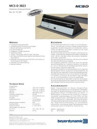
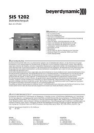
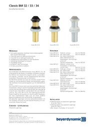
Schwanenhals - Achtung<br />
Zur Vermeidung von Überdehnungen und frühzeitigem Verschleiß<br />
darf der Schwanenhals nur bis max. 90 Grad<br />
gebogen werden.<br />
Gooseneck - Caution<br />
In order to avoid overstretching and premature wear and tear never<br />
bend the gooseneck more than 90°.<br />
Col de Cygne - Attention<br />
Flexion de 90 degrés max. afin d’éviter tout sur-allongement et toute<br />
usure prématurée.
INHALT / CONTENTS / SOMMAIRE<br />
BEDIENUNGSANLEITUNG <strong>MCS</strong> <strong>50</strong><br />
Kurzbeschreibung. . . . . . . . . . . . . . . . . . . . . . . Seite 4<br />
<strong>MCS</strong> <strong>50</strong> Diskussions-Steuereinheit . . . . . . . . . . Seite 8<br />
Installation <strong>MCS</strong> <strong>50</strong> und Sprechstellen . . . . . . . Seite 9<br />
Inbetriebnahme . . . . . . . . . . . . . . . . . . . . . . . . Seite 10<br />
<strong>MCS</strong>-Systemkonfiguration<br />
über <strong>MCS</strong>-Editor . . . . . . . . . . . . . . . . . . . . . . . Seite 15<br />
Glossar . . . . . . . . . . . . . . . . . . . . . . . . . . . . . . . Seite 18<br />
Fehlercheckliste . . . . . . . . . . . . . . . . . . . . . . . . Seite 19<br />
Ausführungen . . . . . . . . . . . . . . . . . . . . . . . . . Seite 20<br />
Zubehör - optional . . . . . . . . . . . . . . . . . . . . . . Seite 20<br />
Technische Daten . . . . . . . . . . . . . . . . . . . . . . . Seite 20<br />
Explosionszeichnung / Ersatzteilliste<br />
<strong>MCS</strong> <strong>50</strong> . . . . . . . . . . . . . . . . . . . . . . . . . . . . . . Seite 26<br />
Explosionszeichnung / Ersatzteilliste<br />
Sprechstellen <strong>MCS</strong> 521, 523 . . . . . . . . . . . . . . Seite 28<br />
Konformitätserklärung . . . . . . . . . . . . . . . . . . . Seite 82<br />
OPERATING INSTRUCTIONS <strong>MCS</strong> <strong>50</strong><br />
Short description . . . . . . . . . . . . . . . . . . . . . . . Page 30<br />
<strong>MCS</strong> <strong>50</strong> Discussion control unit . . . . . . . . . . . . Page 34<br />
Installation of <strong>MCS</strong> <strong>50</strong> and<br />
Microphone units . . . . . . . . . . . . . . . . . . . . . . . Page 35<br />
Setting up . . . . . . . . . . . . . . . . . . . . . . . . . . . . Page 36<br />
<strong>MCS</strong> System Configuration via <strong>MCS</strong>-Editor . . . Page 41<br />
Glossary . . . . . . . . . . . . . . . . . . . . . . . . . . . . . . Page 44<br />
Trouble Shooting . . . . . . . . . . . . . . . . . . . . . . . Page 45<br />
Versions . . . . . . . . . . . . . . . . . . . . . . . . . . . . . . Page 46<br />
Optional Accessories . . . . . . . . . . . . . . . . . . . . Page 46<br />
Technical Specifications. . . . . . . . . . . . . . . . . . . Page 46<br />
Exploded View / Spare Parts <strong>MCS</strong> <strong>50</strong> . . . . . . . . Page 52<br />
Exploded View / Spare Parts<br />
<strong>MCS</strong> 521, 523 Microphone Units . . . . . . . . . . . Page 54<br />
EC-Declaration of Conformity. . . . . . . . . . . . . . Page 82<br />
NOTICE D’UTILISATION <strong>MCS</strong> <strong>50</strong><br />
Description abrégée . . . . . . . . . . . . . . . . . . . . . Page 56<br />
Centrale de contrôle <strong>MCS</strong> <strong>50</strong> . . . . . . . . . . . . . . Page 60<br />
Installation de la centrale <strong>MCS</strong> <strong>50</strong> et<br />
des postes . . . . . . . . . . . . . . . . . . . . . . . . . . . . Page 61<br />
Opération. . . . . . . . . . . . . . . . . . . . . . . . . . . . . Page 62<br />
Configuration du système <strong>MCS</strong> à l’aide<br />
de l’Editeur <strong>MCS</strong> . . . . . . . . . . . . . . . . . . . . . . . Page 67<br />
Glossaire . . . . . . . . . . . . . . . . . . . . . . . . . . . . . Page 70<br />
Dépannage. . . . . . . . . . . . . . . . . . . . . . . . . . . . Page 71<br />
Modèles . . . . . . . . . . . . . . . . . . . . . . . . . . . . . . Page 72<br />
Accessories en option. . . . . . . . . . . . . . . . . . . . Page 72<br />
Spécifications techniques . . . . . . . . . . . . . . . . . Page 72<br />
Exploded View / Spare Parts <strong>MCS</strong> <strong>50</strong> . . . . . . . . Page 78<br />
Exploded View / Spare Parts<br />
<strong>MCS</strong> 521, 523 Microphone Units . . . . . . . . . . . Page 80<br />
EC-Déclaration de Conformité . . . . . . . . . . . . . Page 82<br />
3<br />
english deutsch<br />
français
4<br />
1. Kurzbeschreibung<br />
1.1 <strong>MCS</strong> <strong>50</strong><br />
Die <strong>MCS</strong> <strong>50</strong> ist eine komplette Diskussions-Steuereinheit mit integriertem Netzteil und Prozessorsteuerung für 32 bzw. 64 Sprechstellen. Sie ist ein<br />
Stand-Alone-Gerät mit Multifunktions-Tasten und LC-Display in einem 19"-einbaufähigen Gehäuse. Das System erlaubt den Betrieb der<br />
<strong>MCS</strong>-Standard-Sprechstellen der <strong>50</strong>0er-Serie. Die Diskussions-Steuereinheit wird mit einer hersteller spezifischen Konfiguration geliefert. Der<br />
Anwender sollte jedoch selbst eine Konfiguration vornehmen. Die Konfiguration erfolgt über Multifunktions-Tasten und LC-Display. Eine erweiterte<br />
Konfiguration sollte vor Inbetriebnahme mit dem <strong>MCS</strong>-Editor (im Lieferumfang enthalten) über PC am Serviceport durchgeführt werden. Jede Art<br />
der Konfiguration umfasst die Sprech stellen- und Steuerungs funktion der Diskussions-Steuereinheit. Das System arbeitet im Bus-Betrieb.<br />
Sicherheitsinformationen<br />
Setzen Sie das Gerät niemals Regen oder hoher Feuchtigkeit aus. Installieren Sie es daher nicht in unmittelbarer Nähe von Swimming Pools,<br />
Duschanlagen, feuchten Kellerräumen oder sonstigen Bereichen mit außergewöhnlich hoher Luftfeuchtigkeit.<br />
Leeren Sie niemals Flüssigkeiten in das Gerät.<br />
Installieren und betreiben Sie das Gerät auch niemals in unmittelbarer Nähe von Heizkörpern, Beleuchtungsanlagen oder anderen wärmeerzeugenden<br />
Geräten.<br />
Verlegen Sie alle Kabel stets so, dass sie nicht durch scharfe Gegenstände geknickt oder gar durchgetrennt werden können.<br />
Schalten Sie bei allen Arbeiten an den Ein- und Ausgängen die Stromzufuhr aus.<br />
Überprüfen Sie, ob die Anschlusswerte mit der vorhandenen Netzstromversorgung übereinstimmen. Bei Anschluss des Systems an die falsche<br />
Stromversorgung können ernsthafte Schäden entstehen.<br />
Stecken Sie weder Drähte noch andere Gegenstände durch die Lüftungsöffnungen des Gehäuses.<br />
Sorgen Sie für eine ausreichende Belüftung rund um das Gerät. Behindern Sie die Belüftung nicht durch Abdecken der Lüftungsöfffnungen<br />
mit Gegenständen. Bei Einbau in ein Rack oder ähnliches achten Sie auf einen Mindestabstand von 1 HE oberhalb und unterhalb des Gerätes.<br />
Stellen Sie niemals brennende Gegenstände auf das Gerät.<br />
1.2 Sprechstellen<br />
Für die <strong>MCS</strong> <strong>50</strong> Diskussions-Steuereinheit sind verschiedene Präsidenten- und Delegiertensprechstellen erhältlich:<br />
<strong>MCS</strong> 521 und <strong>MCS</strong> 523 mit Lautsprecher; <strong>MCS</strong> <strong>50</strong>1 und <strong>MCS</strong> <strong>50</strong>3 für den Einbau in Tische.<br />
Alle Sprechstellen (Delegierte und Präsident) sind ausgestattet mit:<br />
fest angeschlossenem Kabel (3 m lang) mit 15-pol. Sub-D-Stecker<br />
15-pol. Sub-D-Buchse<br />
3,5 mm Mono-Klinke als Dokumentationsausgang für den Anschluss von Recordern, Diktiergeräten etc. (außer <strong>MCS</strong> <strong>50</strong>1 und <strong>MCS</strong> <strong>50</strong>3)<br />
Schwanenhalsmikrofon mit Nierencharakteristik.<br />
Duo-LED; leuchtet grün, wenn die Sprechstelle eingeschaltet ist; leuchtet rot, wenn das System im Anmeldemodus arbeitet und signalisiert so<br />
die Anmeldung. Sobald die Zuteilung erfolgt, wechselt die Farbe von rot auf grün.<br />
Leuchtring leuchtet, wenn Mikrofon eingeschaltet ist<br />
DIP-Schalter auf Unterseite zur Programmierung der Sprechstellen (DIP-Schalter 6 hat keine Funktion)<br />
Sprechstellen mit Lautsprecher (<strong>MCS</strong> 521 und <strong>MCS</strong> 523)<br />
O.g. Merkmale, sowie zusätzlich einen Breitbandlautsprecher mit leichtem Neigungswinkel<br />
Einstell-Regler auf der Unterseite für individuelle Ausgangslautstärke der Lautsprecher in der Sprechstelle, regelbar von der eingestellten<br />
Lautstärke der Steuerzentrale <strong>MCS</strong> <strong>50</strong> von 0 dB bis -20 dB (z.B. bei Round-Table-Meetings können die Lautsprecher näher aneinander stehen,<br />
so dass wegen Rückkopplungsgefahr ein Sprechstellen-Lautsprecher leiser gestellt werden kann).<br />
1.2.1 Präsidentensprechstelle <strong>MCS</strong> 523<br />
Die Präsidentensprechstelle ist mit 3 Tasten ausgestattet.<br />
Prior-Taste<br />
Die Funktion der Prior-Taste hängt davon ab, wie sie in der Diskussions-Steuereinheit <strong>MCS</strong> <strong>50</strong> konfiguriert wurde. Der Präsident kann entweder<br />
alle aktivierten Delegierten-Sprechstellen vorübergehend „muten“ oder ganz löschen.<br />
Mikrofon-Taste<br />
Die Mikrofon-Taste hat eine Zuschaltfunktion, sodass sich der Präsident (unabhängig von der NOM), jederzeit in die Diskussion zuschalten kann.<br />
Clear-Taste<br />
Mit der Clear-Taste löscht der Präsident alle aktiven Sprechstellen sowie bei der Betriebsart „Anmeldung“ alle im System angemeldeten<br />
Sprechstellen.<br />
1.2.2 Delegiertensprechstelle <strong>MCS</strong> 521<br />
Die Delegiertensprechstelle ist mit einer Taste, der Mikrofontaste, ausgestattet. Mit dieser Taste können die Delegierten ihre Sprechstelle ein- und<br />
ausschalten bzw. bei der Betriebsart „Anmeldung“ sich im System anmelden.
1.2.3 Sprechstellen <strong>MCS</strong> <strong>50</strong>3 und <strong>MCS</strong> <strong>50</strong>1 für den Tischeinbau<br />
Zur Montage der Einbausprechstelle <strong>MCS</strong> <strong>50</strong>1 (Delegierten sprechstelle) oder <strong>MCS</strong> <strong>50</strong>3 (Präsidentensprechstelle) benötigen Sie in der Tischplatte<br />
einen entsprechend großen Ausschnitt. Siehe hierzu auch die entsprechende Bohrschablone.<br />
Die Sprechstelle montieren Sie mit dem mitgelieferten Befesti gungs material.<br />
Die Delegiertensprechstelle <strong>MCS</strong> <strong>50</strong>1 verfügt über eine Mikrofontaste zum Ein-und Ausschalten der Sprechstelle bzw. zum Anmelden im System<br />
bei der Betriebsart Anmeldung.<br />
Die Präsidentensprechstelle <strong>MCS</strong> <strong>50</strong>3 verfügt neben der Mikrofontaste über eine Prior- und Clear-Taste. Funktionsweise siehe unter<br />
„1.2.1 Präsidentensprechstelle <strong>MCS</strong> 513, <strong>MCS</strong> 523“.<br />
1.2.4 Systemanschlusseinheiten <strong>MCS</strong> 553 L und <strong>MCS</strong> 563 L für Untertischmontage<br />
Die Systemanschlusseinheiten <strong>MCS</strong> 553 L und <strong>MCS</strong> 563 L wurden für die Montage unter dem Tisch entwickelt. Je nach Anzahl der angeschlossenen<br />
Tasten fungieren die Systemanschlusseinheiten als Präsidenten- (3 Tasten: Mikrofon, Prior, Clear) oder Delegierten sprech stelle (1 Taste: Mikrofon).<br />
Mit der <strong>MCS</strong>-Editorsoftware wird die jeweilige Systemanschlusseinheit als Präsident oder Delegierter konfiguriert. Siehe hierzu auch Kapitel<br />
„6. <strong>MCS</strong>-Systemkonfiguration über <strong>MCS</strong>-Editor“.<br />
Montage<br />
Auf der Tischplatte werden entsprechend große Ausschnitte für Mikrofon und Tasten benötigt. Die Systemanschlusseinheiten werden mit je<br />
4 Schrauben unter dem Tisch befestigt. Siehe hierzu auch die jeweilige Bohrschablone.<br />
Anschluss<br />
Die Systemanschlusseinheiten sind mit einem festen Anschlusskabel und einer Anschlussbuchse ausgestattet. Der Anschluss erfolgt gemäß dem<br />
Einkabelprinzip, d.h. die 1. Sprechstelle wird an die Steuerzentrale angeschlossen, die 2. Sprechstelle an die 1. Sprechstelle usw.<br />
Die <strong>MCS</strong> 553 L ist mit einem abnehmbaren Schwanenhalsmikrofon ausgestattet und verfügt über eine Klemmleiste für den Anschluss von Tasten und<br />
einer Klemmleiste für Lautsprecher.<br />
Die <strong>MCS</strong> 563 L verfügt über eine Klemmleiste für den Anschluss von Mikrofon, LED-Ring, Tasten und Lautsprecher.<br />
5<br />
deutsch
6<br />
1.3 Adressierung der Sprechstellen<br />
Bevor das System in Betrieb genommen wird, müssen die Sprechstellen über die DIP-Schalter auf dem Boden gemäß nachfolgender Tabelle<br />
adressiert werden.<br />
ON<br />
1 2 3 4 5 6<br />
Der DIP-Schalter 6 hat keine Funktion.<br />
1 = DIP-Schalter zeigt auf ON = eingeschaltet<br />
0 = DIP-Schalter zeigt auf Zahl = ausgeschaltet<br />
Sprechstellen<br />
1 - 32<br />
Linie 1<br />
1<br />
2<br />
3<br />
4<br />
5<br />
6<br />
7<br />
8<br />
9<br />
10<br />
11<br />
12<br />
13<br />
14<br />
15<br />
16<br />
17<br />
18<br />
19<br />
20<br />
21<br />
22<br />
23<br />
24<br />
25<br />
26<br />
27<br />
28<br />
29<br />
30<br />
31<br />
32<br />
Sprechstellen<br />
33 - 64<br />
Linie 2<br />
(nur <strong>MCS</strong> <strong>50</strong>/64)<br />
33<br />
34<br />
35<br />
36<br />
37<br />
38<br />
39<br />
40<br />
41<br />
42<br />
43<br />
44<br />
45<br />
46<br />
47<br />
48<br />
49<br />
<strong>50</strong><br />
51<br />
52<br />
53<br />
54<br />
55<br />
56<br />
57<br />
58<br />
59<br />
60<br />
61<br />
62<br />
63<br />
64<br />
DIP-Schalter<br />
1<br />
0<br />
1<br />
0<br />
1<br />
0<br />
1<br />
0<br />
1<br />
0<br />
1<br />
0<br />
1<br />
0<br />
1<br />
0<br />
1<br />
0<br />
1<br />
0<br />
1<br />
0<br />
1<br />
0<br />
1<br />
0<br />
1<br />
0<br />
1<br />
0<br />
1<br />
0<br />
1<br />
DIP-Schalter<br />
2<br />
Hinweis:<br />
Werkseitig ist die Sprechstelle 1 als Präsident definiert. Änderungen können über den <strong>MCS</strong>-Editor vorgenommen werden.<br />
Achten Sie bei der Adressierung darauf, dass keine Doppeladressierung innerhalb der gleichen Linie vorkommt. Hilfreich ist der <strong>MCS</strong>-Editor (siehe<br />
Kapitel 6.8 „Statusabfrage“).<br />
Wichtig:<br />
Bei einem Reset (anwender- oder herstellerspezifisch) muss die Präsidentensprechstelle über den <strong>MCS</strong>-Editor neu definiert werden.<br />
0<br />
0<br />
1<br />
1<br />
0<br />
0<br />
1<br />
1<br />
0<br />
0<br />
1<br />
1<br />
0<br />
0<br />
1<br />
1<br />
0<br />
0<br />
1<br />
1<br />
0<br />
0<br />
1<br />
1<br />
0<br />
0<br />
1<br />
1<br />
0<br />
0<br />
1<br />
1<br />
DIP-Schalter<br />
3<br />
0<br />
0<br />
0<br />
0<br />
1<br />
1<br />
1<br />
1<br />
0<br />
0<br />
0<br />
0<br />
1<br />
1<br />
1<br />
1<br />
0<br />
0<br />
0<br />
0<br />
1<br />
1<br />
1<br />
1<br />
0<br />
0<br />
0<br />
0<br />
1<br />
1<br />
1<br />
1<br />
DIP-Schalter<br />
4<br />
0<br />
0<br />
0<br />
0<br />
0<br />
0<br />
0<br />
0<br />
1<br />
1<br />
1<br />
1<br />
1<br />
1<br />
1<br />
1<br />
0<br />
0<br />
0<br />
0<br />
0<br />
0<br />
0<br />
0<br />
1<br />
1<br />
1<br />
1<br />
1<br />
1<br />
1<br />
1<br />
DIP-Schalter<br />
5<br />
0<br />
0<br />
0<br />
0<br />
0<br />
0<br />
0<br />
0<br />
0<br />
0<br />
0<br />
0<br />
0<br />
0<br />
0<br />
0<br />
1<br />
1<br />
1<br />
1<br />
1<br />
1<br />
1<br />
1<br />
1<br />
1<br />
1<br />
1<br />
1<br />
1<br />
1<br />
1
1.4 Pflege der <strong>MCS</strong> Sprechstellen<br />
Zum Reinigen der <strong>MCS</strong> Sprechstellen bei leichten Verschmutzungen wie Fingerabdrücke, Staub, Marmelade oder Fruchtsaft nehmen Sie ein<br />
feuchtes Tuch, Schwamm oder Bürste und einen flüssigen Haushaltsreiniger. Vor der Reinigung muss die Fläche gründlich angefeuchtet werden.<br />
Zum Schluss mit klarem Wasser nachwaschen. Achten Sie darauf, dass kein Wasser in die Mikrofonkapsel oder in das Gehäuse läuft. Bei<br />
Verschmutzungen durch Mineralöle und -fette sowie tierische und pflanzliche Fette können Sie Spiritus, Isopro pyl alkohol oder Reinigungsbenzin<br />
verwenden.<br />
Verschmutzungen durch Kugelschreiber, Farbband oder Kohlepapier behandeln Sie am besten mit Isopropylalkohol oder Spiritus.<br />
Den Poppschutz reinigen Sie am besten mit klarem, warmen Wasser. Achten Sie darauf, dass der Poppschutz vollkommen trocken ist, bevor sie ihn<br />
wieder auf das Mikrofon aufsetzen.<br />
7<br />
deutsch
8<br />
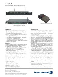
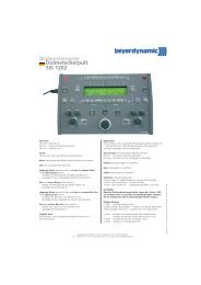
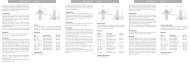
2. <strong>MCS</strong> <strong>50</strong> Diskussions-Steuereinheit<br />
Vorderseite<br />
(1) Ein- und Ausschalter<br />
(2) LC-Display<br />
(3) Master-Reset-Taste, wird diese gedrückt, werden die herstellerspezifischen Parameter (Mittelwerteinstellungen) geladen.<br />
Diese sollen gewährleisten, dass das System in jedem Fall funktioniert, auch wenn eine falsche Einstellung durch den Anwender<br />
vorgenommen wird. Die Master-Reset-Taste ist vertieft angebracht, so dass sie nur mit einem Hilfsmittel (z.B. Kugelschreiber o.ä.)<br />
betätigt werden kann.<br />
Zwei Multifunktionstasten:<br />
(4) Linke Taste „Reset“ allein ca. 12 sek. gedrückt, fungiert als Reset-Taste und setzt alle einstellbaren Parameter auf<br />
anwenderspezifische Parameter zurück (siehe Kapitel 5.3).<br />
(5) Rechte Taste „N.o.m.“ allein gedrückt zeigt die maximale Anzahl der einschaltbaren Delegiertensprechstellen an.<br />
LCD-Anzeige für ca. 10 sec.<br />
(6) Serviceport RS 232-Schnittstelle für Systemkonfiguration mit <strong>MCS</strong>-Editor über PC<br />
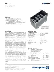
Rückseite<br />
(1) (2) (4) (3) (5)<br />
(6)<br />
Konfiguration<br />
Max NOM 2<br />
Reset N.o.m.<br />
(7) (8) (9) (10) (11) (12) (13) (14)<br />
(7) Audio Output: 3-pol. XLR-Hauptsignalausgang zum Anschluss an Verstärker, Mischpult etc.<br />
(8) Eingang, 3-pol. XLR, symm. (2<strong>50</strong> mV)<br />
(9) Erweiterungseingang, 3-pol. XLR, unsymm. (1,55 V)<br />
(10) Anschluss für Aufnahmegerät, unsymm. (2<strong>50</strong> mV)<br />
(11) Sprechstellenanschluss Line 1, 15-pol. Sub-D-Buchse<br />
(12) Sprechstellenanschluss Line 2, 15-pol. Sub-D-Buchse (nur bei Version <strong>MCS</strong> <strong>50</strong>/64)<br />
(13) RS 232: dient zum Anschluss von Bedien-PC via Mouse oder Touchscreen oder für weitere am Markt befindliche<br />
Konferenzsteuerungssysteme wie z.B. AMX/Panja ® , Crestron ® .<br />
Zum Anschluss ein RS 232 Standardkabel, gerade, (female - male) verwenden.<br />
(14) Netzanschluss
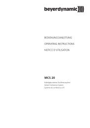
3. Installation <strong>MCS</strong> <strong>50</strong> und Sprechstellen<br />
3.1 Einkabelprinzip<br />
3.2 Stichverkabelung<br />
1. Bevor Sie die <strong>MCS</strong> <strong>50</strong> an das Netz anschließen, überprüfen<br />
Sie bitte die Netzspannung (siehe Kapitel<br />
4. „Netzspannung“).<br />
2. Adressieren Sie die Sprechstellen wie unter Kapitel<br />
1.3 „Adressierung der Sprechstellen“ beschrieben.<br />
3. Schließen Sie die erste Sprechstelle an den Sprechstelleneingang<br />
der Diskussions-Steuereinheit <strong>MCS</strong> <strong>50</strong> an.<br />
Die anderen Sprechstellen werden im Einkabelprinzip<br />
angeschlossen, d.h. die zweite Sprechstelle wird an die<br />
erste angeschlossen, die dritte an die zweite usw.<br />
4. An die <strong>MCS</strong> <strong>50</strong>/32 können max. 32 Sprechstellen angeschlossen<br />
werden, an die <strong>MCS</strong> <strong>50</strong>/64 max. 64 Sprechstellen<br />
in zwei Linien.<br />
1. Bevor Sie die <strong>MCS</strong> <strong>50</strong> an das Netz anschließen, überprüfen<br />
Sie bitte die Netzspannung (siehe Kapitel<br />
4. „Netzspannung“).<br />
2. Adressieren Sie die Sprechstellen wie unter Kapitel<br />
1.3 „Adressierung der Sprechstellen“ beschrieben.<br />
3. Schließen Sie ein 15-pol. Sub-D Kabel an den Sprechstelleneingang<br />
der Diskussions-Steuereinheit <strong>MCS</strong> <strong>50</strong> an.<br />
Schließen Sie an das andere Ende des Kabels einen<br />
Dreifach-Verteiler CA 1513 an. Schließen Sie je zwei<br />
Sprechstellen an einen Dreifach-Verteiler CA 1513 an. An<br />
den letzten Verteiler können max. 3 Sprech stellen angeschlossen<br />
werden.<br />
4. An die <strong>MCS</strong> <strong>50</strong>/32 können max. 32 Sprechstellen angeschlossen<br />
werden, an die <strong>MCS</strong> <strong>50</strong>/64 max. 64 Sprechstellen<br />
in zwei Linien.<br />
Hinweis:<br />
Die Gesamtlänge des Buskabels darf 300 m nicht überschreiten. Jede einzelne Stichleitung in dieser Installation darf nicht länger als 5 m sein.<br />
Sicherheitshinweise<br />
Beim Anschließen, Entfernen oder Adressieren von Sprechstellen, muss die Steuerzentrale <strong>MCS</strong> <strong>50</strong> immer ausgeschaltet sein.<br />
4. Netzspannung / Netzteil<br />
Das Netzteil ist für eine Eingangsspannung von 85 V - 264 V AC (<strong>50</strong>/60 Hz) ausgelegt.<br />
Achtung:<br />
Wenn die Sicherung F101 des integrierten Schaltnetzteils (siehe Nr. 200 in „Explosionszeichnung und Ersatzteilliste Diskussionssteuer zentrale<br />
<strong>MCS</strong> <strong>50</strong>“, Seite 24 bis 25) defekt ist, sollte das gesamte Schaltnetzteil ersetzt werden. Eine andere Sicherung mit einem höheren Wert als 6,3A<br />
kann das Schaltnetzteil zerstören.<br />
Bitte wenden Sie sich an Ihre beyerdynamic-Vertretung.<br />
9<br />
deutsch
10<br />
5. Inbetriebnahme<br />
5.1 Einschalten<br />
beyerdynamic<br />
<strong>MCS</strong> <strong>50</strong> V.1 - Software Version<br />
5.2 Konfiguration<br />
Beim Einschalten führt das System immer einen Systemcheck durch, wobei die abgespei cherten Parameter<br />
überprüft werden. Bei einer Abweichung erscheint eine Fehlermeldung.<br />
Die Konferenzanlage ist betriebsbereit.<br />
Nach dem Systemcheck erscheint die Standard-Anzeige, die die eingestellte Betriebsart (Manuell, Wechsel,<br />
Anmeldung, Automatisch), den Signal-Pegel der angeschlossenen Geräte/Sprechstellen und die tatsächliche<br />
Anzahl der eingeschalteten Mikrofone, einschließlich der Präsidenten sprech stellen anzeigt.<br />
Sollte nebenstehende Fehlermeldung erscheinen, können Sie entweder eine Betriebskonfiguration (siehe<br />
Kapitel 5.2) vornehmen oder die anwenderspezifischen Einstellungen laden und die entsprechenden<br />
Parameter konfigurieren (siehe Kapitel 5.3).<br />
In das Konfigurationsmenü gelangen Sie, wenn Sie bei der eingeschalteten <strong>MCS</strong> <strong>50</strong> beide Tasten gleichzeitig drücken. Die Pfeile im Display zeigen<br />
an, welche Taste am Gerät zu drücken ist, links (Reset) = ▼, rechts (N.o.m.) = ▲. Zum Verlassen der einzelnen Menüpunkte drücken Sie beide Tasten<br />
gleichzeitig. Sie gelangen dann wieder ins Hauptmenü bzw. zurück in den Betriebsmodus. Eine Speicherung erfolgt automatisch.<br />
1. Parameter<br />
Reset N.o.m.<br />
Systemcheck bitte warten<br />
Reset N.o.m.<br />
System O.K.<br />
Reset N.o.m.<br />
Pegel<br />
Wechsel NOM 0<br />
Reset N.o.m.<br />
Falsche Anzahl<br />
Sprechstellen<br />
Reset N.o.m.<br />
Anzahl Mikro<br />
Weiter<br />
Reset N.o.m.<br />
20<br />
- +<br />
Reset N.o.m.<br />
In diesem Menüpunkt wird die Anzahl der tatsächlich angeschlossenen Mikrofone eingestellt. Drücken Sie<br />
die linke Taste (4), um ins Untermenü zu gelangen.<br />
Mit der linken Taste (4) wird die Anzahl absteigend, mit der rechten Taste (5) aufsteigend eingestellt. Maximal<br />
können 32 Sprechstellen eingestellt werden. (Bei optionaler Erweiterung bis zu 64 Sprechstellen.)
2. Parameter<br />
Betriebsart<br />
Weiter<br />
Insgesamt gibt es 3 Betriebsarten:<br />
In diesem Menüpunkt wird die Betriebsart eingestellt.<br />
Möglich sind: Manuell, Wechsel, Anmeldung<br />
In der ersten Zeile erscheint die aktuelle Einstellung. Mit der linken Taste (4) wird die Betriebsart ausgewählt,<br />
mit der rechten Taste (5) wird die ausgewählte Betriebsart bestätigt und erscheint in der ersten Zeile als<br />
aktuelle Betriebsart.<br />
1. Anmeldung<br />
Diese Betriebsart arbeitet nur in Verbindung mit Bedien-PC, Mediensteuersystem (AMX/Panja ® , Crestron ® etc.). Durch Drücken der<br />
Mikrofontaste an der Sprechstelle wird eine Anmeldung im System registriert. Die Zuteilung erfolgt durch den Bediener am PC oder<br />
Touchscreen der Mediensteuerung.<br />
2. Manuell<br />
Jeder Teilnehmer kann sich über die Mikrofontaste selbst in die Diskussion ein- bzw. ausschalten bis die maximale Anzahl der aktiven<br />
Sprechstellen erreicht ist.<br />
3. Wechsel<br />
Jede neuaktivierte Sprechstelle schaltet die vorherige aktive Sprechstelle ab.<br />
3. Parameter<br />
4. Parameter<br />
Reset N.o.m.<br />
Manuell<br />
Wechsel OK<br />
Reset N.o.m.<br />
Tastenfunktion<br />
Weiter<br />
Reset N.o.m.<br />
Tasten<br />
Redezeit<br />
Weiter<br />
Schalten<br />
Reset N.o.m.<br />
Reset N.o.m.<br />
120 Sek<br />
- +<br />
Reset N.o.m.<br />
In diesem Menüpunkt wird die Tastenfunktion in den Sprechstellen eingestellt.<br />
In der ersten Zeile erscheint die aktuelle Einstellung.<br />
Schalten: Die Sprechstelle wird mit der Mikrofontaste ein- und ausgeschaltet.<br />
Tasten: Die Mikrofontaste in der Sprechstelle fungiert als Push-To-Talk-Button (PTT)<br />
d.h. die Sprechstelle ist solange eingeschaltet, wie die Mikrofontaste gedrückt<br />
wird.<br />
In diesem Menüpunkt wird die Redezeit der Delegierten-Sprechstelle eingestellt.<br />
Nach Ablauf der eingestellten Redezeit (hier im Beispiel 120 Sekunden) schaltet die Delegierten sprech stelle<br />
automatisch ab. Mit der linken Taste (4) wird der Wert absteigend, mit der rechten Taste (5) aufsteigend eingestellt.<br />
11<br />
deutsch
12<br />
5. Parameter<br />
Blinkzeit<br />
Weiter<br />
6. Parameter<br />
NOM<br />
Weiter<br />
7. Parameter<br />
Reset N.o.m.<br />
6 Sek<br />
- +<br />
Reset N.o.m.<br />
Reset N.o.m.<br />
Reset N.o.m.<br />
Prior-Taste<br />
Weiter<br />
Mute<br />
2<br />
- +<br />
Reset N.o.m.<br />
Löschen<br />
Reset N.o.m.<br />
Löschen<br />
Mute<br />
Reset N.o.m.<br />
In diesem Menüpunkt wird die Blinkzeit eingestellt; d.h. es wird die Zeit eingestellt, die den Leuchtring in der<br />
Sprechstelle blinken lässt, bevor die Sprechstelle, nach Ablauf der Redezeit abgeschaltet wird.<br />
Die Blinkzeit (hier im Beispiel wurden 6 Sekunden eingestellt) ist nur dann wirksam, wenn zuvor die Redezeit<br />
eingestellt wurde. Mit der linken Taste (4) wird der Wert absteigend, mit der rechten Taste (5) aufsteigend<br />
eingestellt.<br />
In diesem Menüpunkt wird die Anzahl der maximal gleichzeitig einschaltbaren Delegiertensprech stellen<br />
(NOM) eingestellt. Im Betrieb kann diese Einstellung jederzeit über die rechte Taste (5) abgerufen werden.<br />
Die Einstellung sollte unter Berücksichtigung der akustischen Eigenschaften des Einsatz ortes vorgenommen<br />
werden.<br />
Im Beispiel wurde die NOM mit „2“ eingegeben. Mit der linken Taste (4) wird die Anzahl absteigend, mit der<br />
rechten Taste (5) aufsteigend eingestellt.<br />
In diesem Menüpunkt wird die Funktion der Prior-Taste an der Präsidenten-Sprechstelle eingestellt.<br />
In der ersten Zeile erscheint die aktuelle Einstellung. Durch Drücken der linken Taste (4) wird die Ein stellung<br />
gewechselt.<br />
Mute: Bei Drücken der Prior-Taste an der Präsidenten-Sprechstelle kann der Präsident alle aktivierten<br />
Delegiertensprechstellen vorübergehend ausschalten, während er spricht.<br />
Sobald er sein Mikrofon über die Prior-Taste wieder ausschaltet, sind alle vorher eingeschalteten<br />
Delegiertensprechstellen wieder aktiv.<br />
Löschen: Der Präsident kann mit der Prior-Taste alle aktiven Delegiertensprechstellen ausschalten.<br />
Hinweis Konfiguration mit <strong>MCS</strong>-Editor<br />
(siehe auch Seite 14 „Präs. Betriebsart“):<br />
Funktion „Normal“: Präsidentensprechstelle wird eingeschaltet, Delegiertensprechstellen werden ausgeschaltet. Die Delegierten können<br />
ihre Sprechstelle gleich wieder einschalten.<br />
Funktion „Löschen“: Präsidentensprechstelle wird eingeschaltet, Delegiertensprechstellen werden ausgeschaltet und bleiben ausgeschaltet<br />
solange der Präsident spricht.
8. Parameter<br />
Eingangspegel<br />
Weiter<br />
Sprechlinie 1<br />
Weiter<br />
In diesem Menüpunkt können die Parameter für die möglichen Eingangspegel eingestellt werden. Drücken<br />
Sie die linke Taste (4), um in das Untermenü zu gelangen.<br />
Mit der rechten Taste (5) erfolgt die Auswahl zum Einstellen zwischen:<br />
- Sprechlinie 1<br />
- Sprechlinie 2 (nur mit Erweiterungsfeld für weitere 32 Sprechstellen)<br />
- Input<br />
Mit der linken Taste (4) gelangen Sie dann in den ausgewählten Menüpunkt.<br />
In der ersten Zeile erscheint die aktuelle Einstellung. Im Beispiel ist die Sprechlinie 1 eingeschaltet.<br />
Zum Einstellen des Pegels auf die rechte Taste (5) drücken.<br />
Der Pegelwert kann mit der linken Taste (4) absteigend, mit der rechten Taste (5) aufsteigend eingestellt werden.<br />
Wichtig:<br />
Die Sprechlinie 2 ist nur bei der Version <strong>MCS</strong> <strong>50</strong>/64 angeschlossen.<br />
Beim Drücken beider Taster wird der eingestellte Wert gespeichert und Sie gelangen zurück in das Hauptmenü. Für weitere Pegeleinstellungen<br />
müssen Sie wieder wie unter 8. Parameter beschrieben vorgehen.<br />
9. Parameter<br />
Reset N.o.m.<br />
Reset N.o.m.<br />
Ein<br />
Aus Pegel<br />
Reset N.o.m.<br />
-6 dB<br />
- +<br />
Reset N.o.m.<br />
Sprechlinie 2<br />
Weiter<br />
Reset N.o.m.<br />
Ein<br />
Aus<br />
Reset N.o.m.<br />
Ausgangspegel<br />
Weiter<br />
Reset N.o.m.<br />
-4 dB<br />
- +<br />
Reset N.o.m.<br />
In diesem Menüpunkt kann, in Abhängigkeit der akustischen Eigenschaften des Einsatzortes, die Gesamt -<br />
lautstärke der Lautsprecher in den Sprechstellen eingestellt werden. Die Einstellung erfolgt dann, sobald alle<br />
Eingangspegel aufeinander mit gleicher Lautstärke angepasst sind.<br />
Die Einstellung des Ausgangspegels erfolgt in 2 dB-Schritten.<br />
Wichtig:<br />
Die Ausgangspegel am Audio Output (7) und Record (10) für externe Geräte (z.B. externe Beschal -<br />
lungsanlage) bleiben davon unberührt.<br />
13<br />
deutsch
14<br />
10. Parameter<br />
Klangregelung<br />
Weiter<br />
Höhen<br />
Weiter<br />
11. Parameter<br />
Insert<br />
Weiter<br />
Speichern<br />
Reset N.o.m.<br />
Reset N.o.m.<br />
0 dB<br />
- +<br />
Reset N.o.m.<br />
Reset N.o.m.<br />
Ein<br />
Aus<br />
Reset N.o.m.<br />
Systemcheck bitte warten<br />
Reset N.o.m.<br />
System O.K.<br />
Reset N.o.m.<br />
Pegel<br />
Wechsel NOM 0<br />
Reset N.o.m.<br />
In diesem Menüpunkt werden die Höhen und Tiefen der Sprechstellen eingestellt.<br />
Mit der rechten Taste (5) kann zwischen der Einstellung der Höhen und der Tiefen gewählt werden. Mit der<br />
linken Taste (4) gelangen Sie dann in den ausgewählten Menüpunkt.<br />
Die Höhen bzw. Tiefen können zwischen +12 dB und -12 dB eingestellt werden.<br />
Wichtig:<br />
Die Menüpunkte „Insert“ und „Telefon“ haben bei der <strong>MCS</strong> <strong>50</strong> keine Funktion!<br />
Sobald alle Parameter eingegeben wurden, müssen zum Speichern beide Tasten (4) und (5) gleichzeitig<br />
gedrückt werden. Das System bringt eine Speichermeldung und führt automatisch einen System check durch.<br />
Zum Schluss erscheint die Standardanzeige.
5.3 Einstellen der anwenderspezifischen Parameter<br />
Wichtig:<br />
Da das <strong>MCS</strong> System mit herstellerspezifischen Parametern ausgeliefert wird, sollten bei der ersten Inbetriebnahme alle Para meter anwenderspezifisch<br />
eingestellt werden.<br />
Anwenderspezifische<br />
Einstellungen werden geladen<br />
Reset N.o.m.<br />
Anwenderspezifische<br />
Einstellungen werden gespeichert<br />
Reset N.o.m.<br />
6. <strong>MCS</strong>-Systemkonfiguration über <strong>MCS</strong>-Editor<br />
6.1 Systemvoraussetzungen<br />
Zum Einstellen der anwenderspezifischen Parameter, müssen Sie beim Einschalten die rechte (5) und linke (4)<br />
Taste gleichzeitig drücken. Dabei werden die anwenderspezifischen Einstellungen geladen. Die anwenderspezifischen<br />
Parameter müssen zunächst im Konfigurationsmenü, wie unter Punkt 5.2 beschrieben, eingestellt<br />
werden.<br />
Sobald alle anwenderspezifischen Parameter eingestellt sind und Sie das Menü verlassen, werden diese<br />
gespeichert und das System startet von neuem.<br />
PC Pentium 300 MHz oder schneller<br />
Mindestens 8 MB RAM<br />
PC mit Betriebssystem Windows 95, 98 oder Windows NT/2000, XP<br />
1 CD-ROM Laufwerk<br />
1 Festplatte mit 1 MB freiem Speicherplatz<br />
1 Mouse, Trackball oder Touchscreen<br />
1 serielle Schnittstelle RS 232<br />
1 Tastatur<br />
1 entsprechender Monitor<br />
6.2 Installation der <strong>MCS</strong>-Editor-Software<br />
Schalten Sie Ihren PC ein.<br />
Starten Sie Ihr „Windows“-Programm.<br />
Legen Sie die CD-ROM ins Laufwerk.<br />
Wählen Sie im Start-Menü den Programmpunkt „Ausführen“.<br />
Wählen Sie im Laufwerk „D“ das entsprechende Programm aus:<br />
1. Wollen Sie den <strong>MCS</strong>-Editor von der CD-ROM starten, wählen Sie in der Exe.Datei den Editor in Deutsch (<strong>MCS</strong>editd), Englisch<br />
(<strong>MCS</strong>edite) oder Französisch (<strong>MCS</strong>editf).<br />
2. Wollen Sie den <strong>MCS</strong>-Editor auf Ihren PC kopieren und von der Festplatte starten, dann wählen Sie die entsprechende<br />
Sprachdatei aus (Deutsch, Englisch, Französisch) und starten das Setup. Folgen Sie den Anweisungen auf dem Bildschirm<br />
oder geben Sie folgende Befehlszeile ein: D:\Deutsch\setup.exe (falls „D“ Ihr CD-ROM-Laufwerk ist).<br />
Klicken Sie auf OK und folgen Sie den Anweisungen auf dem Bildschirm.<br />
6.3 Anschluss<br />
Verbinden Sie den Serviceport der <strong>MCS</strong> <strong>50</strong> über ein Standard-RS 232-Anschlusskabel mit der seriellen Schnittstelle RS 232 an Ihrem PC.<br />
Werkseitig ist die serielle Schnittstelle „COM 2“ konfiguriert. Änderung siehe Kapitel „6.7 Übertragen der Daten“.<br />
15<br />
deutsch
16<br />
6.4 <strong>MCS</strong> <strong>50</strong> - Erstellung einer neuen Konfiguration<br />
Starten Sie Ihre installierte <strong>MCS</strong>-Editor-Software über das Start-Menü „Programme“.<br />
Rufen Sie das Menü „Datei“ auf und klicken Sie auf den Befehl „Neu“.<br />
Geben Sie die gewünschte Konfiguration in die <strong>MCS</strong>-Editor Maske ein.<br />
Anzahl Mikrofone<br />
Geben Sie die Anzahl der tatsächlich angeschlossenen Mi kro fone/Sprechstellen ein.<br />
Tastenfunktion<br />
Sie können zwischen Tasten und Schalten der Mikrofon taste aller Sprechstellen (Präsident und Delegierte) wählen<br />
(genaue Beschreibung siehe Kapitel „5.2 Konfiguration 3. Parameter“).<br />
Anlage Betriebsart<br />
Sie können unter den Betriebsarten<br />
Anmeldung,<br />
Manuell,<br />
oder Wechsel wählen<br />
(Die Betriebsart Automatik hat keine Funktion.)<br />
max. Anzahl Präsident<br />
Geben Sie die Anzahl der tatsächlich angeschlossenen Präsidentensprechstellen ein.<br />
Präs. Betriebsart<br />
Sie können die Prior-Taste in der Präsidentensprechstelle konfigurieren und zwischen Mute und Löschen wählen<br />
(genaue Beschreibung siehe Kapitel „5.2 Konfiguration 7. Parameter“). In der Betriebsart „Normal“ werden beim<br />
Betätigen der Prior-Taste die Delegiertensprechstellen aus- und die Präsidentensprechstelle eingeschaltet. Es können<br />
sich danach jederzeit weitere Delegierte wieder zuschalten.<br />
NOM<br />
Sie können die Anzahl der maximal einschaltbaren Delegiertensprech stellen<br />
(NOM) einstellen (genaue Beschreibung siehe Kapitel „5.2 Konfiguration 6.<br />
Parameter“).<br />
max. Redezeit<br />
Sie können die Redezeit für die Delegiertensprechstellen eingeben (Std.Std. - Min.Min. - Sek.Sek.) (genaue Beschreibung siehe Kapitel<br />
„5.2 Konfiguration 4. Parameter“).<br />
Blinkzeit<br />
Sie können die Blinkzeit des Leuchtrings in der Sprechstelle einstellen (genaue Beschreibung siehe Kapitel „5.2 Konfiguration<br />
5. Parameter“).
6.5 Mikrofondaten - Definierung von Präsidentensprechstellen<br />
6.6 Speichern<br />
6.7 Übertragen der Daten<br />
Durch Markieren der betreffenden Sprechstelle und Anklicken des Feldes „Präsident“ kann die<br />
Präsidentensprechstelle definiert werden. Es kann auch eine Delegierten sprech stelle als<br />
Präsident definiert werden (siehe Kapitel „1.2 Sprech stellen“ und „1.3 Adres sierung der<br />
Sprechstellen“).<br />
Wichtig: Es können nur so viele Sprechstellen als Präsident definiert werden, wie zuvor unter<br />
dem Feld „max. Anzahl Präsident“ eingegeben wurden.<br />
Im Feld „zu mutende Sprechstellenlautsprecher“ können Sie die Sprechstellen definieren,<br />
deren Lautsprecher gemutet werden sollen (z.B. Nachbarsprechstelle). Diese Funktion sollte<br />
genutzt werden, wenn Sprechstellen zu dicht aneinandergereiht stehen und die Rück -<br />
kopplungsneigung zu früh einsetzt.<br />
Wenn Sie alle Daten eingegeben haben, rufen Sie das Menü „Datei“ und den Befehl<br />
„Speichern“ auf. Vergeben Sie einen Namen für die Datei und klicken Sie auf „OK“.<br />
Sobald eine Änderung vorgenommen wurde, sollten Sie ebenfalls speichern.<br />
Zum Übertragen der Daten auf die Diskussions-Steuereinheit <strong>MCS</strong> <strong>50</strong> rufen Sie das Menü<br />
„Steuerung“ und den Befehl „Übertragen“ auf. Die Daten werden auf die Diskussions-<br />
Steuereinheit <strong>MCS</strong> <strong>50</strong> übertragen. Danach startet die <strong>MCS</strong> <strong>50</strong> einen erneuten Systemcheck und<br />
wenn das System „OK“ ist, erscheint die Standardanzeige im Display.<br />
Hinweis<br />
Sollte ein Verbindungsaufbau nicht zustande kommen, überprüfen Sie die Schnittstellenkonfiguration im <strong>MCS</strong>-Editor. Unter dem Menü „Divers“<br />
und dem Befehl „Konfiguration“ definieren Sie die freie serielle Schnittstelle (werkseitig „COM 2“ eingestellt).<br />
6.8 Statusabfrage<br />
Unter dem Menü „Steuerung“ und dem Befehl „Statusabfrage“ werden alle möglichen 32 Sprech stellen abgefragt.<br />
Auf dem Bildschirm erscheinen die Sprechstellen, die gefunden wurden.<br />
Der Computer unterscheidet die Sprechstellen durch Typen.<br />
Typ 1 = Sprechstelle ohne Lautsprecher<br />
Typ 2 = Sprechstelle mit Lautsprecher<br />
Hinweis<br />
Sollte der PC eine Sprechstelle nicht anzeigen, überprüfen Sie die Adressierung und die Kabelverbindung der Sprechstelle.<br />
17<br />
deutsch
18<br />
6.9 Konfigurationsbeispiel „Anzahl Mikrofone“ (Nur <strong>MCS</strong> <strong>50</strong>/64)<br />
In einer Linie können bis zu 32 Sprechstellen an die Steuerzentrale angeschlossen werden.<br />
Sollen jedoch z.B. in der 1. Linie 16 Sprechstellen und in der 2. Linie 17 Sprechstellen angeschlossen werden, müssen Sie wie nachfolgend beschrieben<br />
vorgehen:<br />
1. <strong>MCS</strong> Editor Software<br />
Geben Sie in das Feld „Anzahl Mikrofone“ die Zahl 64 ein. Nun haben Sie 64 Sprechstellen zum Konfigurieren: 1 bis 32 in Linie 1 und 33 bis<br />
64 in Linie 2, d.h. die Sprechstellen 1 bis 16 in Linie 1 und die Sprechstellen 33 bis <strong>50</strong> in Linie 2 (entspricht den 17 Sprechstellen angeschlossen<br />
an Linie 2). Eine mögliche Präsidentensprechstelle in Linie 2 z.B. Sprechstelle Nr. 7 entspricht im <strong>MCS</strong> Editor Sprechstelle Nr. 40. Speichern Sie<br />
diese Konfiguration und übertragen Sie die Daten auf die Steuerzentrale.<br />
Die Steuerzentrale sucht nun nach 64 Sprechstellen, es sind aber insgesamt nur 33 angeschlossen.<br />
Gehen Sie folgendermaßen vor:<br />
2. <strong>MCS</strong> Steuerzentrale<br />
Schließen Sie die <strong>MCS</strong> Editor Software bzw. trennen Sie den PC von der Steuerzentrale.<br />
Starten Sie die Konfiguration an der Steuerzentrale über die Multifunktionstasten und LC-Display.<br />
Geben Sie die Anzahl der Mikrofone (in diesem Beispiel 33) in das Konfigurationsmenü ein. Siehe auch Kapitel „5.2 Konfiguration“.<br />
Wenn Sie die Konfiguration beendet haben, arbeitet das System mit 33 Sprechstellen.<br />
Im Systemcheck sucht die Steuerzentrale dann nach 33 Sprechstellen und findet diese auch.<br />
7. Glossar<br />
Konfiguration Einstellen aller Parameter.<br />
Herstellerspezifisch Werkseitig eingestellte Parameter (Mittelwerteinstellungen), die auf Wunsch geändert werden können.<br />
Diese werden durch Drücken der Reset-Taste (6) geladen.<br />
Anwenderspezifisch Durch den Anwender eingestellte Parameter, die bei einem Reset geladen werden.<br />
Diese werden durch Drücken der Reset-Taste (4) geladen.<br />
Betriebsspezifisch Eingestellte Parameter und deren Änderung zum/im Betrieb des Systems.<br />
NOM Number of Open Microphones = Anzahl der Mikrofone, die gleichzeitig eingeschaltet sind.<br />
Parameter Einstellbare Werte, z.B. Anzahl der angeschlossenen Mikrofone, Betriebsart, Eingangspegel,<br />
Ausgangspegel.<br />
PTT Push-To-Talk = einstellbarer Betriebsmodus für Sprechstelle, wobei das Mikrofon solange eingeschaltet ist,<br />
wie die Mikrofontaste an der Sprechstelle gedrückt wird.<br />
Reset Zurücksetzen aller Parameter auf die ursprüngliche anwender- bzw. herstellerspezifische Konfiguration.<br />
Systemcheck Selbständige Überprüfung aller Parameter des Systems, die beim Einschalten durchgeführt wird.
8. Fehlercheckliste<br />
Fehler<br />
Fehlermeldung im Display<br />
„Falsche Anzahl Sprechstellen“<br />
Kein Ton bei eingeschalteten Sprechstellen<br />
Ton zerrt<br />
Kein Verbindungsaufbau von PC (<strong>MCS</strong>-Editor<br />
zu <strong>MCS</strong> <strong>50</strong>)<br />
Es funktionieren nicht mehr wie z.B. 5<br />
Sprechstellen<br />
Alle Sprechstellen blinken<br />
Nach Reset (anwender- + herstellerspezifisch)<br />
funktioniert Präsidenten sprechstelle nicht<br />
mehr<br />
Kein Ton über Sprechstellenlautsprecher, aber<br />
Mikrofon funktioniert<br />
Mögliche Ursache<br />
Zu wenig oder zu viel Sprechstellen als in der<br />
Konfiguration festgelegt<br />
Betriebsspannung der Sprechstelle fehlt,<br />
dadurch gibt die Sprechstelle keine Adresse<br />
ab<br />
Kabelverbindung unterbrochen<br />
Eingang abgeschaltet<br />
Pegel des jeweiligen Eingangsverstärkers ist<br />
zu gering eingestellt<br />
Eingangsschaltung übersteuert<br />
Defektes Kabel<br />
Falsche Schnittstelle im <strong>MCS</strong>-Editor konfiguriert<br />
Datenbustreiber wurde durch Anschließen<br />
von Sprechstellen während des Betriebs zerstört<br />
Sprechstelle doppelt adressiert<br />
Präsidentendefinition fehlt<br />
Insertfunktion aktiviert<br />
Neu konfigurieren<br />
Lösung<br />
Mit Hilfe von <strong>MCS</strong>-Editor Sprechstellen überprüfen<br />
(siehe Kapitel 6.8 Statusab frage)<br />
Mit Hilfe von <strong>MCS</strong>-Editor Sprechstellen überprüfen<br />
und Verbindung zur fehlenden<br />
Sprechstelle herstellen<br />
Mit Hilfe von <strong>MCS</strong>-Editor schalten Sie in der<br />
Konfiguration den Eingang ein<br />
Mit Hilfe der Funktionstasten an der<br />
<strong>MCS</strong> <strong>50</strong> den Pegel des jeweiligen Ein gangs -<br />
verstärkers erhöhen (8. Parameter)<br />
Mit Hilfe der Funktionstasten an der<br />
<strong>MCS</strong> <strong>50</strong> den Ton des jeweiligen Ein gangs<br />
runterregeln (10. Parameter)<br />
Neues Kabel anschließen<br />
Mit Hilfe von <strong>MCS</strong>-Editor freie Schnittstelle<br />
konfigurieren<br />
Service anrufen oder Fachbetrieb aufsuchen<br />
Adresse der Sprechstellen überprüfen<br />
Konfiguration der Präsidenten sprech stelle<br />
über <strong>MCS</strong>-Editor eingeben (siehe 6.5<br />
Mikrofondaten - Definierung von<br />
Präsidentensprechstellen)<br />
Schalten Sie die Insertfunktion aus (siehe<br />
5.2 Konfiguration 11. Parameter)<br />
19<br />
deutsch
20<br />
9. Ausführungen<br />
Diskussions-Steuereinheit<br />
<strong>MCS</strong> <strong>50</strong>/32 Diskussions-Steuereinheit für bis zu 32 Sprechstellen . . . . . . . . . . . . . . . . . . . . . . . . . . . . . Best.-Nr. 459.275<br />
<strong>MCS</strong> <strong>50</strong>/64 Diskussions-Steuereinheit für bis zu 64 Sprechstellen . . . . . . . . . . . . . . . . . . . . . . . . . . . . . Best.-Nr. 463.388<br />
Sprechstellen<br />
<strong>MCS</strong> <strong>50</strong>1 Delegiertensprechstelle für Tischeinbau. . . . . . . . . . . . . . . . . . . . . . . . . . . . . . . . . . . . . . . . Best.-Nr. 470.422<br />
<strong>MCS</strong> 521 Delegiertensprechstelle mit Mikrofontaste und Lautsprecher . . . . . . . . . . . . . . . . . . . . . . . . Best.-Nr. 459.305<br />
<strong>MCS</strong> <strong>50</strong>3 Präsidentensprechstelle für Tischeinbau. . . . . . . . . . . . . . . . . . . . . . . . . . . . . . . . . . . . . . . . Best.-Nr. 470.430<br />
<strong>MCS</strong> 523 Präsidentensprechstelle mit Mikrofontaste und Lautsprecher. . . . . . . . . . . . . . . . . . . . . . . . Best.-Nr. 459.313<br />
<strong>MCS</strong> 553 L Systemanschlusseinheit für Untertischmontage mit abnehmbaren<br />
Schwanenhalsmikrofon sowie Klemmleiste für Tasten und Lautsprecher . . . . . . . . . . . . . . . Best.-Nr. 471.119<br />
<strong>MCS</strong> 563 L Systemanschlusseinheit für Untertischmontage mit Klemmleiste für<br />
Mikrofon, LED-Ring, Tasten und Lautsprecher . . . . . . . . . . . . . . . . . . . . . . . . . . . . . . . . . . . Best.-Nr. 471.127<br />
10. Zubehör - optional<br />
Software<br />
<strong>MCS</strong> Controller Bedien- und Konfigurationssoftware für PC-Steuerung unter Windows ® . . . . . . . . . . . . . . . Best.-Nr. 454.435<br />
Konferenz-Zubehör<br />
CA 1241 Piezotaster ohne Beschriftung . . . . . . . . . . . . . . . . . . . . . . . . . . . . . . . . . . . . . . . . . . . . . . . Best.-Nr. 546.658<br />
CA 1241 P Piezotaster mit Beschriftung „Prior“ . . . . . . . . . . . . . . . . . . . . . . . . . . . . . . . . . . . . . . . . . . Best.-Nr. 546.666<br />
CA 1241 C Piezotaster mit Beschriftung „Clear“. . . . . . . . . . . . . . . . . . . . . . . . . . . . . . . . . . . . . . . . . . Best.-Nr. 546.674<br />
CA 1242 Hubtaster mit integriertem zweifarbigen Leuchtring . . . . . . . . . . . . . . . . . . . . . . . . . . . . . . Best.-Nr. 486.329<br />
CA 1<strong>50</strong>2 Verbindungskabel 15-Pin Sub-D, 2,5 m lang . . . . . . . . . . . . . . . . . . . . . . . . . . . . . . . . . . . . Best.-Nr. 451.002<br />
CA 1510 Verbindungskabel 15-Pin Sub-D, 10 m lang . . . . . . . . . . . . . . . . . . . . . . . . . . . . . . . . . . . . Best.-Nr. 451.010<br />
CA 1513 15-Pin Sub-D Y-Adapter, 1 Eingang, 3 Ausgänge . . . . . . . . . . . . . . . . . . . . . . . . . . . . . . . . Best.-Nr. 4<strong>50</strong>.308<br />
<strong>MCS</strong> 10 Transportkoffer für 10 Sprechstellen und Diskussions-Steuereinheit. . . . . . . . . . . . . . . . . . . Best.-Nr. 466.948<br />
MPC 22 E Kondensatorgrenzflächenmikrofon (Halbniere), schwarz, ohne Vorverstärker,<br />
zur Decken- oder Tischmontage, für <strong>MCS</strong> 563 L. . . . . . . . . . . . . . . . . . . . . . . . . . . . . . . . . Best.-Nr. 465.194<br />
SHM 214 E Schwanenhalsmikrofon, Länge 400 mm, steckbar, mit starrem Endstück (Rohr),<br />
XLR-Stecker und Leuchtring, ohne Vorverstärker, für <strong>MCS</strong> 563 L. . . . . . . . . . . . . . . . . . . . . Best.-Nr. 464.635<br />
SHM 215 E dito, jedoch Länge <strong>50</strong>0 mm . . . . . . . . . . . . . . . . . . . . . . . . . . . . . . . . . . . . . . . . . . . . . . . . Best.-Nr. 464.708<br />
11. Technische Daten<br />
Diskussions-Steuereinheit <strong>MCS</strong> <strong>50</strong><br />
Anschlüsse<br />
Netzanschluss . . . . . . . . . . . . . . . . . . . . . . . . . . . . . . . . . 3-polig<br />
RS 232 Schnittstelle . . . . . . . . . . . . . . . . . . . . . . . . . . . . . 9-pol. Sub-D-Buchse<br />
Service RS 232 Schnittstelle (Frontseite) . . . . . . . . . . . . . . 9-pol. Sub-D-Buchse<br />
NF-Input und NF-Output . . . . . . . . . . . . . . . . . . . . . . . . . 3-pol. XLR<br />
Eingangspegel (Aux) . . . . . . . . . . . . . . . . . . . . . . . . . . . . max. 2<strong>50</strong> mV symm.<br />
Ausgangspegel (Audio Output) . . . . . . . . . . . . . . . . . . . . max. 1,55 V symm.<br />
Ausgang Aufnahme (Record) . . . . . . . . . . . . . . . . . . . . . . 2<strong>50</strong> mV unsymm.<br />
Input Erweiterung (Extension) . . . . . . . . . . . . . . . . . . . . . 1,55 V unsymm.<br />
Konferenzbus (Line 1) . . . . . . . . . . . . . . . . . . . . . . . . . . . 15-pol. Sub-D-Buchse, max. 32 Sprechstellen<br />
Konferenzbus (Line 2) . . . . . . . . . . . . . . . . . . . . . . . . . . . 15-pol. Sub-D-Buchse, max. 32 Sprechstellen (nur bei <strong>MCS</strong> <strong>50</strong>/64!)<br />
Anzeige . . . . . . . . . . . . . . . . . . . . . . . . . . . . . . . . . . . . . . LC-Display 2 x 16 Zeichen<br />
Schalter - Taster . . . . . . . . . . . . . . . . . . . . . . . . . . . . . . . . Ein-/Ausschalter<br />
eine Reset-Taste für anwenderspezifische Einstellungen<br />
eine N.o.m-Taste<br />
eine Master-Reset-Taste für herstellerspezifische Einstellungen<br />
Abmessungen (B x H x T) . . . . . . . . . . . . . . . . . . . . . . . . . 19", 2HE (4<strong>50</strong> x 134 x 320 mm)<br />
Gewicht . . . . . . . . . . . . . . . . . . . . . . . . . . . . . . . . . . . . . . 5,7 kg<br />
Netzteil<br />
Netzspannung . . . . . . . . . . . . . . . . . . . . . . . . . . . . . . . . . 85 V bis 264 V AC (<strong>50</strong>/60 Hz)<br />
Ausgangsspannung . . . . . . . . . . . . . . . . . . . . . . . . . . . . . +24 V, +5 V, +15 V, -15 V<br />
Leistungsaufnahme . . . . . . . . . . . . . . . . . . . . . . . . . . . . . 38 W (<strong>MCS</strong> <strong>50</strong>/32)<br />
60 W (<strong>MCS</strong> <strong>50</strong>/64)<br />
Ausgangsstrom bei +24 V . . . . . . . . . . . . . . . . . . . . . . . . 6 A<br />
Restwelligkeit. . . . . . . . . . . . . . . . . . . . . . . . . . . . . . . . . . 1<strong>50</strong> mVpp<br />
Umgebungstemperatur . . . . . . . . . . . . . . . . . . . . . . . . . . 0°C bis +<strong>50</strong>°C<br />
Luftfeuchtigkeit . . . . . . . . . . . . . . . . . . . . . . . . . . . . . . . . max. 90%<br />
Schutzmaßnahmen . . . . . . . . . . . . . . . . . . . . . . . . . . . . . überlast-, dauerkurzschluss- und leerlauffest
Audio<br />
Frequenzgang . . . . . . . . . . . . . . . . . . . . . . . . . . . . . . . . . 80 Hz bis 19.000 Hz<br />
Klirrfaktor . . . . . . . . . . . . . . . . . . . . . . . . . . . . . . . . . . . . ≤ 1%<br />
Stromversorgung . . . . . . . . . . . . . . . . . . . . . . . . . . . . . . . +24 V, +5 V, +15 V, -15 V<br />
Stromaufnahme bei +24 V. . . . . . . . . . . . . . . . . . . . . . . . 80 mA, 60 mA, 72 mA, 33 mA<br />
XLR-Stecker<br />
NF-Ausgang AF . . . . . . . . . . . . . . . . . . . . . . . . . . . . . . . . Stift 2+, 3- und 1 Schirm, symm., erdfrei, 1,55 V (+6 dBm)<br />
Konferenzbus Line 1 und Line 2<br />
NF-Eingang . . . . . . . . . . . . . . . . . . . . . . . . . . . . . . . . . . . 0 Ohm Summe, Stift 7+, 6- und 14 Schirm, symm, erdfrei, regelbar -40 dB<br />
NF-Ausgang . . . . . . . . . . . . . . . . . . . . . . . . . . . . . . . . . . . 1,55 V (+6 dBm), Stift 5+, 4- und 12 Schirm, symm., erdfrei, regelbar -40 dB<br />
Stromversorgung Ausgang. . . . . . . . . . . . . . . . . . . . . . . . Stift 1 und 9 +24 V, 6 A<br />
Daten-Bus-Leitung (CPU) . . . . . . . . . . . . . . . . . . . . . . . . . Stift 2 = A, Stift 3 = B, Stift 10 = Schirm<br />
gemäß RS 485 Standard<br />
Max. Kabellänge . . . . . . . . . . . . . . . . . . . . . . . . . . . . . . . 300 m<br />
Delegiertensprechstelle <strong>MCS</strong> 521<br />
Stromversorgung . . . . . . . . . . . . . . . . . . . . . . . . . . . . . . . +24 V über Konferenzbus-Leitung<br />
Stromaufnahme . . . . . . . . . . . . . . . . . . . . . . . . . . . . . . . . max. 100 mA<br />
NF-Übertragungsbereich . . . . . . . . . . . . . . . . . . . . . . . . . 80 Hz bis 19.000 Hz<br />
Klirrfaktor . . . . . . . . . . . . . . . . . . . . . . . . . . . . . . . . . . . . ≤ 1%<br />
Geräuschspannungsabstand mit Mikrofon . . . . . . . . . . . . ≥ 59 dB bezogen auf 1 Pa<br />
NF-Output (+6 dBm) . . . . . . . . . . . . . . . . . . . . . . . . . . . . symmetrisch über Konferenzbus-Leitung<br />
NF-Output (-10 dBm) . . . . . . . . . . . . . . . . . . . . . . . . . . . . unsymmetrisch über 3,5 mm Klinkenbuchse<br />
Limiter . . . . . . . . . . . . . . . . . . . . . . . . . . . . . . . . . . . . . . . für eine größere Variation des Besprechungsabstandes, nicht abschaltbar<br />
Mikrofon . . . . . . . . . . . . . . . . . . . . . . . . . . . . . . . . . . . . . Schwanenhalsmikrofon mit Leuchtring SHM 214 C 02 fest angeschlossen<br />
Lautsprechersystem . . . . . . . . . . . . . . . . . . . . . . . . . . . . . breitbandiger, eingebauter Lautsprecher<br />
Lautstärkeregler für Lautsprecher-Output . . . . . . . . . . . . . Regelbereich 0 dB bis -20 dB<br />
1 Taste . . . . . . . . . . . . . . . . . . . . . . . . . . . . . . . . . . . . . . . Mikrofon-Taste<br />
1 DIP-Schalter (Nr. 6) . . . . . . . . . . . . . . . . . . . . . . . . . . . . keine Funktion<br />
5 DIP-Schalter (Nr. 1 bis 5) . . . . . . . . . . . . . . . . . . . . . . . . Sprechstellenadressierung<br />
Anschlüsse . . . . . . . . . . . . . . . . . . . . . . . . . . . . . . . . . . . . 1 x 3 m Kabel mit 15-pol. Sub-D-Stecker, Konferenzbus<br />
1 x 15-pol. Sub-D-Buchse, Konferenzbus<br />
1 x 3,5 mm Klinkenbuchse, Dokumentationsausgang<br />
Abmessungen (ohne Mikrofon) . . . . . . . . . . . . . . . . . . . . Länge: 190 mm<br />
Breite: 155 mm<br />
Höhe: 52 mm<br />
Gewicht (mit Mikrofon und Anschlusskabel) . . . . . . . . . . 1<strong>50</strong>0 g<br />
Umgebungstemperatur . . . . . . . . . . . . . . . . . . . . . . . . . . 0° - <strong>50</strong>°C<br />
Farbe . . . . . . . . . . . . . . . . . . . . . . . . . . . . . . . . . . . . . . . . Nextel ® , steingrau<br />
Präsidentensprechstelle <strong>MCS</strong> 523<br />
Stromversorgung . . . . . . . . . . . . . . . . . . . . . . . . . . . . . . . +24 V über Konferenzbus-Leitung<br />
Stromaufnahme . . . . . . . . . . . . . . . . . . . . . . . . . . . . . . . . max. 100 mA<br />
NF-Übertragungsbereich . . . . . . . . . . . . . . . . . . . . . . . . . 80 Hz bis 19.000 Hz<br />
Klirrfaktor . . . . . . . . . . . . . . . . . . . . . . . . . . . . . . . . . . . . ≤ 1%<br />
Geräuschspannungsabstand mit Mikrofon . . . . . . . . . . . . ≥ 59 dB bezogen auf 1 Pa<br />
NF-Output (+6 dBm) . . . . . . . . . . . . . . . . . . . . . . . . . . . . symmetrisch über Konferenzbus-Leitung<br />
NF-Output (-10 dBm) . . . . . . . . . . . . . . . . . . . . . . . . . . . . unsymmetrisch über 3,5 mm Klinkenbuchse<br />
Limiter . . . . . . . . . . . . . . . . . . . . . . . . . . . . . . . . . . . . . . . für eine größere Variation des Besprechungsabstandes, nicht abschaltbar<br />
Mikrofon . . . . . . . . . . . . . . . . . . . . . . . . . . . . . . . . . . . . . Schwanenhalsmikrofon mit Leuchtring SHM 214 C 02 fest angeschlossen<br />
Lautsprechersystem . . . . . . . . . . . . . . . . . . . . . . . . . . . . . breitbandiger, eingebauter Lautsprecher<br />
Lautstärkeregler für Lautsprecher Output . . . . . . . . . . . . . Regelbereich 0 dB bis -20 dB<br />
3 Tasten . . . . . . . . . . . . . . . . . . . . . . . . . . . . . . . . . . . . . . 1. Prior-Taste<br />
2. Mikrofon-Taste<br />
3. Clear-Taste<br />
1 DIP-Schalter (Nr. 6) . . . . . . . . . . . . . . . . . . . . . . . . . . . . keine Funktion<br />
5 DIP-Schalter (Nr. 1 bis 5) . . . . . . . . . . . . . . . . . . . . . . . . Sprechstellenadressierung<br />
Anschlüsse . . . . . . . . . . . . . . . . . . . . . . . . . . . . . . . . . . . . 1 x 3 m Kabel mit 15-pol. Sub-D-Stecker, Konferenzbus<br />
1 x 15-pol. Sub-D-Buchse, Konferenzbus<br />
1 x 3,5 mm Klinkenbuchse, Dokumentationsausgang<br />
Abmessungen (ohne Mikrofon) . . . . . . . . . . . . . . . . . . . . Länge: 190 mm<br />
Breite: 155 mm<br />
Höhe: 52 mm<br />
Gewicht (ohne Mikrofon). . . . . . . . . . . . . . . . . . . . . . . . . 1<strong>50</strong>0 g<br />
Umgebungstemperatur . . . . . . . . . . . . . . . . . . . . . . . . . . 0° - <strong>50</strong>°C<br />
Farbe . . . . . . . . . . . . . . . . . . . . . . . . . . . . . . . . . . . . . . . . Nextel ® , steingrau<br />
21<br />
deutsch
22<br />
Delegiertensprechstelle <strong>MCS</strong> <strong>50</strong>1<br />
Stromversorgung . . . . . . . . . . . . . . . . . . . . . . . . . . . . . . . +24 V über Konferenzbus-Leitung<br />
Stromaufnahme . . . . . . . . . . . . . . . . . . . . . . . . . . . . . . . . max. 84 mA<br />
NF-Übertragungsbereich . . . . . . . . . . . . . . . . . . . . . . . . . 80 Hz bis 19.000 Hz<br />
Klirrfaktor . . . . . . . . . . . . . . . . . . . . . . . . . . . . . . . . . . . . ≤ 1%<br />
Geräuschspannungsabstand mit Mikrofon . . . . . . . . . . . . 59 dB bezogen auf 1 Pa<br />
NF-Output (+6 dBm) . . . . . . . . . . . . . . . . . . . . . . . . . . . . symmetrisch über Konferenzbus-Leitung<br />
Limiter . . . . . . . . . . . . . . . . . . . . . . . . . . . . . . . . . . . . . . . für eine größere Variation des Besprechungsabstandes, nicht abschaltbar<br />
Mikrofon . . . . . . . . . . . . . . . . . . . . . . . . . . . . . . . . . . . . . Schwanenhalsmikrofon mit Leuchtring SHM 214 C 02 fest angeschlossen<br />
1 Taste . . . . . . . . . . . . . . . . . . . . . . . . . . . . . . . . . . . . . . . Mikrofon-Taste<br />
1 DIP-Schalter (Nr. 6) . . . . . . . . . . . . . . . . . . . . . . . . . . . . keine Funktion<br />
5 DIP-Schalter (Nr. 1 bis 5) . . . . . . . . . . . . . . . . . . . . . . . . Sprechstellenadressierung<br />
Anschlüsse . . . . . . . . . . . . . . . . . . . . . . . . . . . . . . . . . . . . 1 x 3 m Kabel mit 15-pol. Sub-D-Stecker, Konferenzbus, auftragsbezogen<br />
kann das Kabel in Sonderlängen und lose geliefert werden,<br />
Preise und weitere Informationen auf Anfrage<br />
1 x 15-pol. Sub-D-Buchse, Konferenzbus<br />
Abmessungen (ohne Mikrofon) . . . . . . . . . . . . . . . . . . . . Länge: 170 mm<br />
Breite: 110 mm<br />
Höhe: 4 mm (Frontplatte); gesamt: ca. 30 mm<br />
Gewicht (mit Mikrofon und Anschlusskabel) . . . . . . . . . . 1090 g<br />
Umgebungstemperatur . . . . . . . . . . . . . . . . . . . . . . . . . . 0° bis +<strong>50</strong>°C<br />
Farbe . . . . . . . . . . . . . . . . . . . . . . . . . . . . . . . . . . . . . . . . Nextel ® , steingrau<br />
Präsidentensprechstelle <strong>MCS</strong> <strong>50</strong>3<br />
Stromversorgung . . . . . . . . . . . . . . . . . . . . . . . . . . . . . . . +24 V über Konferenzbus-Leitung<br />
Stromaufnahme . . . . . . . . . . . . . . . . . . . . . . . . . . . . . . . . max. 84 mA<br />
NF-Übertragungsbereich . . . . . . . . . . . . . . . . . . . . . . . . . 80 Hz bis 19.000 Hz<br />
Klirrfaktor . . . . . . . . . . . . . . . . . . . . . . . . . . . . . . . . . . . . ≤ 1%<br />
Geräuschspannungsabstand mit Mikrofon . . . . . . . . . . . . 59 dB bezogen auf 1 Pa<br />
NF-Output (+6 dBm) . . . . . . . . . . . . . . . . . . . . . . . . . . . . symmetrisch über Konferenzbus-Leitung<br />
Limiter . . . . . . . . . . . . . . . . . . . . . . . . . . . . . . . . . . . . . . . für eine größere Variation des Besprechungsabstandes, nicht abschaltbar<br />
Mikrofon . . . . . . . . . . . . . . . . . . . . . . . . . . . . . . . . . . . . . Schwanenhalsmikrofon mit Leuchtring SHM 214 C 02 fest angeschlossen<br />
3 Tasten . . . . . . . . . . . . . . . . . . . . . . . . . . . . . . . . . . . . . . 1. Prior-Taste<br />
2. Mikrofon-Taste<br />
3. Clear-Taste<br />
1 DIP-Schalter (Nr. 6) . . . . . . . . . . . . . . . . . . . . . . . . . . . . keine Funktion<br />
5 DIP-Schalter (Nr. 1 bis 5) . . . . . . . . . . . . . . . . . . . . . . . . Sprechstellenadressierung<br />
Anschlüsse . . . . . . . . . . . . . . . . . . . . . . . . . . . . . . . . . . . . 1 x 3 m Kabel mit 15-pol. Sub-D-Stecker, Konferenzbus, auftragsbezogen<br />
kann das Kabel in Sonderlängen und lose geliefert werden,<br />
Preis und weitere Informationen auf Anfrage<br />
1 x 15-pol. Sub-D-Buchse, Konferenzbus<br />
Abmessungen (ohne Mikrofon) . . . . . . . . . . . . . . . . . . . . Länge: 170 mm<br />
Breite: 110 mm<br />
Höhe: 4 mm (Frontplatte); gesamt: ca. 30 mm<br />
Gewicht (mit Mikrofon und Anschlusskabel) . . . . . . . . . . 1090 g<br />
Umgebungstemperatur . . . . . . . . . . . . . . . . . . . . . . . . . . 0° bis +<strong>50</strong>°C<br />
Farbe . . . . . . . . . . . . . . . . . . . . . . . . . . . . . . . . . . . . . . . . Nextel ® , steingrau<br />
Systemanschlusseinheit <strong>MCS</strong> 553 L (wird nur kundenspezifisch gefertigt)<br />
Stromversorgung . . . . . . . . . . . . . . . . . . . . . . . . . . . . . . . +24 V über Konferenzbus-Leitung<br />
Stromaufnahme . . . . . . . . . . . . . . . . . . . . . . . . . . . . . . . . max. 100 mA<br />
NF-Übertragungsbereich . . . . . . . . . . . . . . . . . . . . . . . . . 80 Hz bis 19.000 Hz<br />
Klirrfaktor . . . . . . . . . . . . . . . . . . . . . . . . . . . . . . . . . . . . ≤ 1%<br />
Geräuschspannungsabstand mit Mikrofon . . . . . . . . . . . . 59 dB bezogen auf 1 Pa<br />
NF-Output (+6 dBm) . . . . . . . . . . . . . . . . . . . . . . . . . . . . symmetrisch über Konferenzbus-Leitung<br />
Limiter . . . . . . . . . . . . . . . . . . . . . . . . . . . . . . . . . . . . . . . für eine größere Variation des Besprechungsabstandes, nicht abschaltbar<br />
6 DIP-Schalter (Nr. 1 bis 5) . . . . . . . . . . . . . . . . . . . . . . . . Sprechstellenadressierung<br />
DIP-Schalter Nr. 6. . . . . . . . . . . . . . . . . . . . . . . . . . . . . . . hat keine Funktion<br />
Anschlüsse . . . . . . . . . . . . . . . . . . . . . . . . . . . . . . . . . . . . 1 x 3 m Kabel mit 15-pol. Sub-D-Stecker, Konferenzbus, auftragsbezogen<br />
kann das Kabel in Sonderlängen und lose geliefert werden,<br />
Preis und weitere Informationen auf Anfrage<br />
1 x 15-pol. Sub-D-Buchse, Konferenzbus<br />
1 x Klinken-Schnellsteckbuchse für<br />
Schwanenhalsmikrofon mit Leuchtring<br />
12-fach Klemmleiste (abnehmbar) für . . . . . . . . . . . . . . . Prior-Taste<br />
Mikrofontaste<br />
Clear-Taste<br />
LED-Anzeige „Mikrofon ein“ (grün),<br />
24 V / 20 mA ohne Vorwiderstand<br />
LED-Anzeige „Anmeldung“ (rot),<br />
24 V / 20 mA ohne Vorwiderstand<br />
Lautsprecheranschluss
Abmessungen (ohne Mikrofon) . . . . . . . . . . . . . . . . . . . . Länge: 203 mm<br />
Breite: 97 mm<br />
Höhe: 47 mm<br />
Gewicht (mit Mikrofon und Anschlusskabel) . . . . . . . . . . 868 g<br />
Umgebungstemperatur . . . . . . . . . . . . . . . . . . . . . . . . . . 0° bis +<strong>50</strong>°C<br />
Option . . . . . . . . . . . . . . . . . . . . . . . . . . . . . . . . . . . . . . . Piezo-Taster mit Duo-Leuchtring (Best.-Nr. 546.658)<br />
Piezo-Taster mit „Clear“-Beschriftung (Best.-Nr. 546.674)<br />
Piezo-Taster mit „Prior“-Beschriftung (Best.-Nr. 546.666)<br />
Mikrofon für <strong>MCS</strong> 553 L<br />
Wandlerprinzip. . . . . . . . . . . . . . . . . . . . . . . . . . . . . . . . . Elektret-Kondensator<br />
Akustische Arbeitsweise. . . . . . . . . . . . . . . . . . . . . . . . . . Druckgradientenempfänger<br />
Richtcharakteristik . . . . . . . . . . . . . . . . . . . . . . . . . . . . . . Niere<br />
Übertragungsbereich . . . . . . . . . . . . . . . . . . . . . . . . . . . . 100 Hz bis 19.000 Hz<br />
Feldleerlaufübertragungsfaktor . . . . . . . . . . . . . . . . . . . . 20 mV/Pa<br />
Nennimpedanz. . . . . . . . . . . . . . . . . . . . . . . . . . . . . . . . . ≤ 1,5 kΩ<br />
Nennabschlussimpedanz . . . . . . . . . . . . . . . . . . . . . . . . . > 8 kΩ<br />
Max. Grenzschalldruckpegel<br />
f = 1 kHz, k ≤ 1%, RL = 8 kΩ . . . . . . . . . . . . . . . . . . . . . 120 dB<br />
Geräuschspannung . . . . . . . . . . . . . . . . . . . . . . . . . . . . . 20 µVs<br />
Geräuschspannungsabstand bez. auf 1 Pa . . . . . . . . . . . . 60 dB<br />
A-bewerteter Äquivalentschalldruckpegel . . . . . . . . . . . . 26 dB<br />
Beschaltung . . . . . . . . . . . . . . . . . . . . . . . . . . . . . . . . . . . unsymmetrisch mit Schnellsteckverbindung ø 7,2 mm<br />
Speisespannung . . . . . . . . . . . . . . . . . . . . . . . . . . . . . . . . 10 V mit Vorwiderstand 10 kΩ<br />
Stromaufnahme . . . . . . . . . . . . . . . . . . . . . . . . . . . . . . . . 400 µA<br />
Leuchtring<br />
Speisespannung . . . . . . . . . . . . . . . . . . . . . . . . . . . . . . . . 24 V, Vorwiderstand 3,3 kΩ<br />
Stromaufnahme . . . . . . . . . . . . . . . . . . . . . . . . . . . . . . . . 20 mA<br />
Abmessungen<br />
Länge. . . . . . . . . . . . . . . . . . . . . . . . . . . . . . . . . . . . . . . . 400 mm<br />
Kopfdurchmesser . . . . . . . . . . . . . . . . . . . . . . . . . . . . . . . 13,5 mm<br />
Schwanenhalsdurchmesser. . . . . . . . . . . . . . . . . . . . . . . . 8 mm<br />
Schwanenhalsbefestigung . . . . . . . . . . . . . . . . . . . . . . . . M 13 x 1 Außengewinde<br />
Gewicht . . . . . . . . . . . . . . . . . . . . . . . . . . . . . . . . . . . . . . 174 g<br />
Farbe . . . . . . . . . . . . . . . . . . . . . . . . . . . . . . . . . . . . . . . . Nextel ® , steingrau (B2)<br />
Das Schwanenhalsmikrofon kann in verschiedenen Längen sowie Ausführungen gefertigt werden.<br />
Anschluss <strong>MCS</strong> 553 L<br />
ACHTUNG:<br />
Verwenden Sie zum Anschluss der Sprechstellen an die <strong>MCS</strong>-Zentrale und der Sprechstelle untereinander nur von beyerdynamic empfohlene<br />
Anschlusskabel (siehe unter „Zubehör - optional“).<br />
Bei Verwendung selbstkonfektionierter Kabel muss auf korrekte Belegung geachtet werden, da sonst Sprechstellen und Zentrale zerstört werden<br />
können. In diesem Fall entfallen alle Garantieansprüche.<br />
Wichtig:<br />
Netzkabel und signalführende Leitungen müssen in einem ausreichenden Abstand zueinander und zur Sprechstelle verlegt werden!<br />
23<br />
deutsch
24<br />
Systemanschlusseinheit <strong>MCS</strong> 563 L (wird nur kundenspezifisch gefertigt)<br />
Stromversorgung . . . . . . . . . . . . . . . . . . . . . . . . . . . . . . . +24 V über Konferenzbus-Leitung<br />
Stromaufnahme . . . . . . . . . . . . . . . . . . . . . . . . . . . . . . . . max. 100 mA<br />
NF-Übertragungsbereich . . . . . . . . . . . . . . . . . . . . . . . . . 80 Hz bis 19.000 Hz<br />
Klirrfaktor . . . . . . . . . . . . . . . . . . . . . . . . . . . . . . . . . . . . ≤ 1%<br />
Geräuschspannungsabstand mit Mikrofon . . . . . . . . . . . . 59 dB bezogen auf 1 Pa<br />
NF-Output (+6 dBm) . . . . . . . . . . . . . . . . . . . . . . . . . . . . symmetrisch über Konferenzbus-Leitung<br />
Limiter . . . . . . . . . . . . . . . . . . . . . . . . . . . . . . . . . . . . . . . für eine größere Variation des Besprechungsabstandes, nicht abschaltbar<br />
6 DIP-Schalter (Nr. 1 bis 5) . . . . . . . . . . . . . . . . . . . . . . . . Sprechstellenadressierung<br />
DIP-Schalter Nr. 6. . . . . . . . . . . . . . . . . . . . . . . . . . . . . . . hat keine Funktion<br />
Anschlüsse . . . . . . . . . . . . . . . . . . . . . . . . . . . . . . . . . . . . 1 x 3 m Kabel mit 15-pol. Sub-D-Stecker, Konferenzbus, auftragsbezogen<br />
kann das Kabel in Sonderlängen und lose geliefert werden,<br />
Preis und weitere Informationen auf Anfrage<br />
1 x 15-pol. Sub-D-Buchse, Konferenzbus<br />
12-fach Klemmleiste (abnehmbar) für . . . . . . . . . . . . . . . Prior-Taste<br />
Mikrofontaste<br />
Clear-Taste<br />
LED-Anzeige „Mikrofon ein“ (grün),<br />
24 V / 20 mA ohne Vorwiderstand<br />
LED-Anzeige „Anmeldung“ (rot),<br />
24 V / 20 mA ohne Vorwiderstand<br />
Mikrofon<br />
Lautsprecheranschluss<br />
Abmessungen (ohne Mikrofon) . . . . . . . . . . . . . . . . . . . . Länge: 203 mm<br />
Breite: 97 mm<br />
Höhe: 47 mm<br />
Gewicht (mit Anschlusskabel). . . . . . . . . . . . . . . . . . . . . . 862 g<br />
Umgebungstemperatur . . . . . . . . . . . . . . . . . . . . . . . . . . 0° bis +<strong>50</strong>°C<br />
Option . . . . . . . . . . . . . . . . . . . . . . . . . . . . . . . . . . . . . . . Piezo-Taster mit Duo-Leuchtring (Best.-Nr. 546.658)<br />
Piezo-Taster mit „Clear“-Beschriftung (Best.-Nr. 546.674)<br />
Piezo-Taster mit „Prior“-Beschriftung (Best.-Nr. 546.666)<br />
Anschluss <strong>MCS</strong> 563 L<br />
ACHTUNG:<br />
Verwenden Sie zum Anschluss der Sprechstellen an die <strong>MCS</strong>-Zentrale und der Sprechstelle untereinander nur von beyerdynamic empfohlene<br />
Anschlusskabel (siehe unter „Zubehör - optional“).<br />
Bei Verwendung selbstkonfektionierter Kabel muss auf korrekte Belegung geachtet werden, da sonst Sprechstellen und Zentrale zerstört werden<br />
können. In diesem Fall entfallen alle Garantieansprüche.<br />
Wichtig:<br />
Netzkabel und signalführende Leitungen müssen in einem ausreichenden Abstand zueinander und zur Sprechstelle verlegt werden!
25<br />
deutsch
26<br />
Explosionszeichnungen und Ersatzteillisten<br />
Diskussionssteuerzentrale <strong>MCS</strong> <strong>50</strong>
Abb.Nr.<br />
10<br />
20<br />
30<br />
40<br />
<strong>50</strong><br />
60<br />
70<br />
80<br />
90<br />
100<br />
110<br />
120<br />
130<br />
140<br />
1<strong>50</strong><br />
160<br />
170<br />
180<br />
190<br />
200<br />
210<br />
220<br />
230<br />
240<br />
2<strong>50</strong><br />
260<br />
270<br />
280<br />
290<br />
300<br />
310<br />
320<br />
330<br />
340<br />
3<strong>50</strong><br />
360<br />
370<br />
380<br />
390<br />
8000<br />
9800<br />
Teil.Nr.<br />
553.093<br />
553.387<br />
322.881<br />
391.018<br />
553.433<br />
<strong>50</strong>3.576<br />
553.182<br />
252.581<br />
535.419<br />
283.371<br />
142.727<br />
187.194<br />
538.698<br />
231.940<br />
142.727<br />
284.858<br />
538.825<br />
516.791<br />
552.518<br />
554.480<br />
554.464<br />
554.472<br />
545.473<br />
529.834<br />
538.833<br />
321.303<br />
554.227<br />
551.473<br />
391.018<br />
553.794<br />
143.278<br />
142.727<br />
553.514<br />
551.473<br />
391.018<br />
553.794<br />
143.278<br />
142.727<br />
122.424<br />
324.264<br />
118.826<br />
Zeichnung Nr.<br />
BN 17-640/A<br />
BN 17-644/A<br />
Best.-Nr. 544.873 schwarz<br />
DIN 965-M 3 x 8<br />
BN 56-990/A<br />
DIN 965-M 5 x 12<br />
41 L 07563 600GNGE300<br />
Nr. 1802.0102<br />
B 24-635.00-00<br />
BN 37-36/5,7 (Alt/I)<br />
DIN 934-M 3<br />
DIN 6797-J 3,2<br />
B 24-642.00-00<br />
BN 37-36/7,5 (Alt/I)<br />
DIN 934-M 3<br />
DIN 125-A 3,2<br />
B 7-660.00-00<br />
4-40 UNC<br />
KES 3SI<br />
LEB1<strong>50</strong>F-0524-Z35/SN<br />
B 21-67.00-00<br />
B 21-68.00-00<br />
H 19, 0XB19, 0XD 6,0<br />
PLT.6SM-C B 1,8L 71D0,75<br />
B 7-659.00-00<br />
DIN 965-M 4 X10<br />
B 24-640.01-00<br />
Best.-Nr. 680096<br />
DIN 965-M 3 X 8<br />
BN 48-141/A<br />
DIN 137-A 3<br />
DIN 934-M 3<br />
B 24-698.00-00<br />
Best.-Nr. 680096<br />
DIN 965-M 3 X 8<br />
BN 48-141/A<br />
DIN 137-A 3<br />
DIN 934-M 3<br />
DIN 7981-B 2,9 X 9,5<br />
<strong>50</strong>,00 X 20,00 Al-matt<br />
3 X 0,75<br />
Bezeichnung<br />
Gehäuse, Oberteil<br />
Gehäuse, Unterteil<br />
Klebefuss<br />
Senkschraube<br />
Frontplatte<br />
Senkschraube<br />
Litze<br />
Netzwippschalter<br />
Tastenplatte<br />
Hülse<br />
6-Kant-Mutter<br />
Zahnscheibe<br />
LCD-Display<br />
Hülse<br />
6-Kant-Mutter<br />
Scheibe<br />
Verbindungskabel<br />
Gewindebolzen<br />
Gerätestecker<br />
Schaltnetzteil<br />
Kabelbaum<br />
Kabelbaum<br />
Klebesockel<br />
Kabelbinder<br />
Verbindungskabel<br />
Senkschraube<br />
Processorplatte<br />
Abstandshalter<br />
Senkschraube<br />
Abstandsbolzen<br />
Federscheibe<br />
6-Kant-Mutter<br />
Analogplatte<br />
Abstandshalter<br />
Senkschraube<br />
Abstandsbolzen<br />
Federscheibe<br />
6-Kant-Mutter<br />
Blechschraube<br />
Aufkleber<br />
Netzkabel<br />
27<br />
deutsch
28<br />
Sprechstellen <strong>MCS</strong> 521, 523
Abb.Nr.<br />
5<br />
10<br />
15<br />
20<br />
30<br />
35<br />
40<br />
<strong>50</strong><br />
<strong>50</strong><br />
55<br />
60<br />
65<br />
70<br />
80<br />
80<br />
80<br />
80<br />
100<br />
110<br />
120<br />
8000<br />
Teil.Nr.<br />
533.807<br />
533.815<br />
524.719<br />
553.409<br />
187.135<br />
554.049<br />
553530<br />
553.425<br />
553.417<br />
533.904<br />
551.872<br />
454.478<br />
528.862<br />
554.413<br />
554.421<br />
554.448<br />
554.456<br />
533.777<br />
528.862<br />
148.105<br />
324.264<br />
Zeichnung Nr.<br />
BN 55-65/A<br />
BN 54-211/A<br />
LPR 8602-Mini 6,4 mm<br />
BN 56-989/A<br />
DIN 6797-A 3,2<br />
3 x 8 Torx<br />
B 7-676.00-00<br />
BN 17-642/B<br />
BN 17-642/A<br />
BF-66-208 Nr. 040 66 208<br />
B 7-655.04-00<br />
SHM 21-8/400-M13-GR<br />
M 2,5x 6 Torx<br />
B 24-703.01-00<br />
B 24-703.02-00<br />
B 24-703.03-00<br />
B 24-703.04-00<br />
BN 55-65/B<br />
M 2,5x 6 Torx<br />
SJ <strong>50</strong>12 SW<br />
<strong>50</strong>,00 x 20,00 AL-Matt<br />
Bezeichnung<br />
Boden<br />
Abschirmdeckel<br />
Abstandshalter<br />
Rückplatte<br />
Zahnscheibe<br />
Linsenschraube<br />
Anschlusskabel<br />
Gehäuse (<strong>MCS</strong> 513 + <strong>MCS</strong> 523)<br />
Gehäuse (<strong>MCS</strong> 511 + <strong>MCS</strong> 521)<br />
Lautsprecher (<strong>MCS</strong> 521 + <strong>MCS</strong> 523)<br />
Anschlusskabel<br />
SH-Mikrofon<br />
Linsenschraube<br />
Trägerplatte (<strong>MCS</strong> 511)<br />
Trägerplatte (<strong>MCS</strong> 513)<br />
Trägerplatte (<strong>MCS</strong> 521)<br />
Trägerplatte (<strong>MCS</strong> 523)<br />
Boden<br />
Linsenschraube<br />
Elastikpuffer<br />
Aufkleber<br />
29<br />
deutsch
30<br />
1. Short Description<br />
1.1 <strong>MCS</strong> <strong>50</strong><br />
The <strong>MCS</strong> <strong>50</strong> is a self-contained discussion control unit with integrated power supply and processor control for 32 or 64 microphone units. It is a<br />
stand alone unit with multi-function buttons and LC-Display in a desktop housing that is suitable for 19" rack mounting. With this system the<br />
<strong>50</strong>0-series microphone units can be operated. The discussion control unit is delivered with a manufacturer specific configuration. The user, however,<br />
can carry out a configuration of the system by himself. The configuration is controlled by using the multi-function buttons and the LC-Display. For an<br />
extensive configuration, a PC can be connected to the service port and the supplied <strong>MCS</strong>-Editor software must be used. All functions of the<br />
discussion control unit can be configured using this software. The system operates in a bus mode.<br />
Safety Information<br />
Never expose the unit to water or excessive humidity. Do not install near swimming pools, spas, in a wet basement or in other excessively<br />
humid environments.<br />
Never pour any liquids into the unit.<br />
Do not install or use this unit near sources of high heat, such as radiators, heat registers, flood lamps, spotlights, stoves, or other appliances.<br />
Always route cables running to the unit where they will not be pinched or cut by heavy or sharp objects.<br />
Always turn off the power to the amplifier when making input or output connections.<br />
Verify that the voltage rating of the unit matches that of the AC mains outlet you are to use. If you connect the unit to the wrong voltage,<br />
you may seriously damage it.<br />
Do not put wires or small objects through any of the ventilation grilles. Electric shock may result.<br />
This unit needs a sufficient ventilation. Therefore, never cover the ventilation grilles. If you install the unit into a rack leave a minimum distance<br />
of 1 U above and below the unit.<br />
Never place burning objects onto the unit.<br />
1.2 Microphone Units<br />
For the <strong>MCS</strong> <strong>50</strong> discussion control unit there are various chairman and delegate microphone units available:<br />
<strong>MCS</strong> 521 and <strong>MCS</strong> 523 with loudspeaker.; <strong>MCS</strong> <strong>50</strong>1 and <strong>MCS</strong> <strong>50</strong>3 for installation into tables.<br />
All microphone units (delegates and chairman) are equipped as follows.<br />
A connecting cable (3 m long) with a 15-pin Sub-D plug.<br />
A 15-pin Sub-D socket.<br />
A mini Mono jack for the connection of recorders, dictating machines etc. (except <strong>MCS</strong> <strong>50</strong>1 and <strong>MCS</strong> <strong>50</strong>3)<br />
A cardioid gooseneck microphone.<br />
A Dual colour LED that illuminates green when the microphone unit is switched on. When the system is operating in the Request-to-Talk mode,<br />
the LED is illuminated red to indicate the registration as a Request-to-Talk. When the microphone is ready, the colour changes to green.<br />
An illuminated ring to indicate the Ready-to-Talk condition of the microphone unit, when the microphone is switched on.<br />
On the bottom of the microphone units there are DIP-switches for programming the microphone units (the DIP-switch no. 6 has no function).<br />
Microphone Units with Loudspeakers (<strong>MCS</strong> 521 and <strong>MCS</strong> 523)<br />
Same as above with built-in wide-range loudspeaker.<br />
On the bottom of the unit there is an individual output volume control for the loudspeaker adjustable from 0 dB to -20 dB this is in addition to<br />
the system level which is controlled via the <strong>MCS</strong> <strong>50</strong> (installation circumstances may demand lower loudspeaker levels to avoid feedback).<br />
1.2.1 <strong>MCS</strong> 523 Chairman Microphone Unit<br />
The chairman microphone unit is equipped with 3 buttons.<br />
Priority button<br />
The function of the priority button depends on how it has been configured in the <strong>MCS</strong> <strong>50</strong> discussion control unit. The chairman can either mute or<br />
clear all activated delegate microphone units.<br />
Microphone button<br />
The microphone button allows the chairman to switch on his microphone unit independingly from the number of open microphones at any time.<br />
Clear button<br />
Pressing the clear button, the chairman clears all activated microphone units. In the Request-to-Talk mode all registered microphone units are also<br />
cleared.<br />
1.2.2 <strong>MCS</strong> 521 Delegate Microphone Unit<br />
The delegate microphone unit is equipped with one button, the microphone button. Using this button, the delegates can switch their microphone<br />
unit on and off or register in the Request-to-Talk mode.
1.2.3 <strong>MCS</strong> <strong>50</strong>3 and <strong>MCS</strong> <strong>50</strong>1 Microphone Units for Table Mounting<br />
To install the <strong>MCS</strong> <strong>50</strong>1 (delegate version) or <strong>MCS</strong> <strong>50</strong>3 (chairman version) microphone unit into a table, you need an appropriate piece cut out of the<br />
table. Please refer to the appropriate template.<br />
Then mount the microphone unit with the supplied fittings.<br />
The <strong>MCS</strong> <strong>50</strong>1 delegate microphone unit has a microphone button to switch the microphone unit on and off or to register the microphone unit in<br />
the system with the “Request-to-Speak” operating mode.<br />
The <strong>MCS</strong> <strong>50</strong>3 chairman microphone unit has a microphone button, priority and clear button. For function please refer to “1.2.1 Chairman<br />
Microphone <strong>MCS</strong> 513, <strong>MCS</strong> 523”.<br />
1.2.4 <strong>MCS</strong> 553 L and <strong>MCS</strong> 563 L System Unit for Mounting under the Table<br />
The <strong>MCS</strong> 553 L and <strong>MCS</strong> 563 L system units have been developed for mounting under the table. Depending on the number of the connected<br />
buttons the system units work as chairman unit (3 buttons: microphone, priority, clear) or delegate unit (1 button: microphone). Using the<br />
<strong>MCS</strong> Editor software, the system unit is configured as chairman or delegate. Please refer also to chapter “6. <strong>MCS</strong> System Configuration via<br />
<strong>MCS</strong> Editor”.<br />
Mounting<br />
There are holes needed in the table for the microphone and the buttons. Each system unit is mounted with 4 screws under the table. Please refer to<br />
the appropriate template.<br />
Connection<br />
The system units are fitted with a fixed connecting cable and a connecting socket. The connection is according to the single cable principle, i.e. the<br />
1st system unit is connected to the control unit, the 2nd system unit to the 1st system unit and so on.<br />
The <strong>MCS</strong> 553 L is fitted with a detachable gooseneck microphone and a terminal board for the connection of buttons and a loudspeaker.<br />
The <strong>MCS</strong> 563 L is fitted with a terminal board for the connection of microphone, LED ring, buttons and loudspeaker.<br />
31<br />
english
32<br />
1.3 Addressing the Microphone Units<br />
Before the system is set up, the microphone units have to be addressed via DIP-switches on the bottom according to the following table.<br />
ON<br />
1 2 3 4 5 6<br />
The DIP-switch 6 has no function.<br />
Microphones<br />
1 - 32<br />
Line 1<br />
1<br />
2<br />
3<br />
4<br />
5<br />
6<br />
7<br />
8<br />
9<br />
10<br />
11<br />
12<br />
13<br />
14<br />
15<br />
16<br />
17<br />
18<br />
19<br />
20<br />
21<br />
22<br />
23<br />
24<br />
25<br />
26<br />
27<br />
28<br />
29<br />
30<br />
31<br />
32<br />
1 = DIP-switch in ON position = switched on<br />
0 = DIP-switch in a number position = switched off<br />
Microphones<br />
33 - 64<br />
Line 2<br />
(only <strong>MCS</strong> <strong>50</strong>/64)<br />
33<br />
34<br />
35<br />
36<br />
37<br />
38<br />
39<br />
40<br />
41<br />
42<br />
43<br />
44<br />
45<br />
46<br />
47<br />
48<br />
49<br />
<strong>50</strong><br />
51<br />
52<br />
53<br />
54<br />
55<br />
56<br />
57<br />
58<br />
59<br />
60<br />
61<br />
62<br />
63<br />
64<br />
DIP-switch<br />
1<br />
0<br />
1<br />
0<br />
1<br />
0<br />
1<br />
0<br />
1<br />
0<br />
1<br />
0<br />
1<br />
0<br />
1<br />
0<br />
1<br />
0<br />
1<br />
0<br />
1<br />
0<br />
1<br />
0<br />
1<br />
0<br />
1<br />
0<br />
1<br />
0<br />
1<br />
0<br />
1<br />
DIP-switch<br />
2<br />
Note:<br />
At the factory the microphone unit 1 has been configured as a chairman microphone unit. Using the <strong>MCS</strong>-Editor another microphone unit can be<br />
chosen as a chairman microphone unit.<br />
Furthermore, make sure that there are not two microphone units having the same address within the same line. For assistance use the <strong>MCS</strong>-Editor<br />
(refer to chapter 6.8 “Status Check”).<br />
Important:<br />
The chairman microphone unit has to be defined again with the <strong>MCS</strong>-Editor, when there is a reset necessary (user or manufacturer specific).<br />
0<br />
0<br />
1<br />
1<br />
0<br />
0<br />
1<br />
1<br />
0<br />
0<br />
1<br />
1<br />
0<br />
0<br />
1<br />
1<br />
0<br />
0<br />
1<br />
1<br />
0<br />
0<br />
1<br />
1<br />
0<br />
0<br />
1<br />
1<br />
0<br />
0<br />
1<br />
1<br />
DIP-switch<br />
3<br />
0<br />
0<br />
0<br />
0<br />
1<br />
1<br />
1<br />
1<br />
0<br />
0<br />
0<br />
0<br />
1<br />
1<br />
1<br />
1<br />
0<br />
0<br />
0<br />
0<br />
1<br />
1<br />
1<br />
1<br />
0<br />
0<br />
0<br />
0<br />
1<br />
1<br />
1<br />
1<br />
DIP-switch<br />
4<br />
0<br />
0<br />
0<br />
0<br />
0<br />
0<br />
0<br />
0<br />
1<br />
1<br />
1<br />
1<br />
1<br />
1<br />
1<br />
1<br />
0<br />
0<br />
0<br />
0<br />
0<br />
0<br />
0<br />
0<br />
1<br />
1<br />
1<br />
1<br />
1<br />
1<br />
1<br />
1<br />
DIP-switch<br />
5<br />
0<br />
0<br />
0<br />
0<br />
0<br />
0<br />
0<br />
0<br />
0<br />
0<br />
0<br />
0<br />
0<br />
0<br />
0<br />
0<br />
1<br />
1<br />
1<br />
1<br />
1<br />
1<br />
1<br />
1<br />
1<br />
1<br />
1<br />
1<br />
1<br />
1<br />
1<br />
1
1.4 Maintenance of the <strong>MCS</strong> Microphone Units<br />
For cleaning the <strong>MCS</strong> microphone units when they are slightly dirty (finger prints, dust, jam or juice) use a soft, damp cloth, sponge or brush and a<br />
liquid cleaning agent. Before cleaning the surface it must be moistened thoroughly. Afterwards it must be cleaned with clear water. Make sure not to<br />
allow any water to enter the unit. For dirt caused by mineral oils and fats, animal and vegetable fats use spirit, isopropyl alcohol or benzine.<br />
For dirt caused by ballpoint pens, typewriter ribbons or carbon paper use isopropyl alcohol or spirit.<br />
Clean the supplied pop shield with clear water. Make sure that it is completely dry before you put it on the microphone again.<br />
33<br />
english
34<br />
2. <strong>MCS</strong> <strong>50</strong> Discussion Control Unit<br />
Front view<br />
(1) Power switch<br />
(2) LC-Display<br />
(3) Master-Reset-button. If this button is pressed, the manufacturer specific parameters (average adjustments) are loaded. They guarantee a system<br />
operation even if the user carries out an incorrect adjustment. As the Master-Reset-button is countersunk use a pen or something like that<br />
for pressing.<br />
Two multi-function buttons:<br />
(4) Left button “Reset” pressed alone for approximately 12 seconds resets all adjustable parameters to user specific adjustments (refer to<br />
chapter 5.3).<br />
(5) Right button “N.o.m.” pressed alone shows the maximum number of switchable delegate microphone units for approximately 10 seconds.<br />
(6) Serviceport, RS 232 interface for system configuration with the <strong>MCS</strong>-Editor via PC<br />
Rear view<br />
(1) (2) (4) (3) (5)<br />
(6)<br />
Configuration<br />
Max NOM 2<br />
Reset N.o.m.<br />
(7) (8) (9) (10) (11) (12) (13) (14)<br />
(7) Audio output: 3-pin XLR output for the connection of amplifiers, mixing consoles etc.<br />
(8) Input, 3-pin XLR, balanced (2<strong>50</strong> mV)<br />
(9) Extension input, 3-pin XLR, unbalanced (1,55 V)<br />
(10) Record: Connection to record documentations (2<strong>50</strong> mV)<br />
(11) Microphones Line 1, 15-pin Sub-D socket<br />
(12) Microphones Line 2, 15-pin Sub-D socket (<strong>MCS</strong> <strong>50</strong>/64 version only!)<br />
(13) RS 232 for the connection of an operator’s PC (operation via mouse or touchscreen) or other available conference systems such as AMX ® ,<br />
Crestron ® . Use a standard RS 232 cable, straight, (female - male).<br />
(14) Mains
3. Installation of <strong>MCS</strong> <strong>50</strong> and Microphone Units<br />
3.1 Single Cable Connection<br />
3.2 Branch Cabling<br />
1. Before connecting the <strong>MCS</strong> <strong>50</strong> to the mains, please check<br />
the supply voltage (refer to chapter 4. “Supply Voltage”).<br />
2. Address the microphone units as described in the chapter<br />
1.3 “Addressing the microphone units”.<br />
3. Connect the first microphone unit to the line input of the<br />
<strong>MCS</strong> <strong>50</strong> discussion control unit. The other microphone<br />
units are connected according to the single cable principle,<br />
i.e. the second microphone unit is connected to the first<br />
one, the third to the second one etc.<br />
4. It is possible to connect up to 32 microphone units in one<br />
line to the <strong>MCS</strong> <strong>50</strong>/32 and up to 64 microphone units in<br />
two lines to the <strong>MCS</strong> <strong>50</strong>/64.<br />
1. Before connecting the <strong>MCS</strong> <strong>50</strong> to the mains, please check<br />
the supply voltage (refer to chapter 4. “Supply Voltage”).<br />
2. Address the microphone units as described in the chapter<br />
1.3 “Addressing the microphone units”.<br />
3. Connect a 15-pin Sub-D cable to the line input of the<br />
<strong>MCS</strong> <strong>50</strong> discussion control unit. Connect a CA 1513<br />
triple distributor to the other end of the cable. Connect<br />
two microphone units to the CA 1513 triple distributor.<br />
The last triple distributor in the line allows to connect<br />
3 microphone units.<br />
4. It is possible to connect up to 32 microphone units in one<br />
line to the <strong>MCS</strong> <strong>50</strong>/32 and up to 64 microphone units in<br />
two lines to the <strong>MCS</strong> <strong>50</strong>/64.<br />
Note:<br />
The total length of the bus cable must not exceed 300 m. Each branch cable in this installation must not exceed 5 m.<br />
Safety instructions<br />
Make sure that the <strong>MCS</strong> <strong>50</strong> discussion control unit is always switched off when connecting, disconnecting or addressing the microphone<br />
units.<br />
4. Supply Voltage / Power Supply<br />
The power supply unit has been developed for an input voltage of 85 V to 264 V AC (<strong>50</strong>/60 Hz).<br />
Caution:<br />
If the F101 fuse of the integrated power supply (refer also to No. 200 in “Exploded View and Spare Parts, <strong>MCS</strong> <strong>50</strong> Discussion Control Unit”, page 48<br />
to 49) is defective, you should replace the whole part. A different fuse with a higher value than 6.3 A can destroy the power supply.<br />
Please contact your beyerdynamic-dealer.<br />
35<br />
english
36<br />
5. Setting up<br />
5.1 Switching on<br />
beyerdynamic<br />
<strong>MCS</strong> <strong>50</strong> V.1 - Software Version (E)<br />
5.2 Configuration<br />
When the system is switched on it carries out a system check checking all stored parameters. An error<br />
message appears at a deviation.<br />
System O.K. = the conference system is ready for operation<br />
After the system check the default screen appears indicating the adjusted mode (Autonomy, Override,<br />
Request-to-talk, Automatic), the signal level of the connected devices/microphone units and the actual<br />
number of switched on microphones, including chairman microphone units.<br />
If this error message occurs, carry out a configuration (refer to chapter 5.2 “Configuration” or adjust the user<br />
specific parameters and configurate the corresponding parameters (refer to chapter “5.3 Adjusting the user<br />
specific parameters”).<br />
You access the configuration menu when you press both buttons simultaneously of the switched on <strong>MCS</strong> <strong>50</strong>. The arrows in the display indicate<br />
which buttons of the device have to be pressed, left (Reset) = ▼, right (N.o.m.) = ▲. To exit the individual menu items press both buttons simultaneously.<br />
You will access the main menu again or return to the operation mode. The entered data is stored automatically.<br />
1. Parameter<br />
Reset N.o.m.<br />
System check please wait<br />
Reset N.o.m.<br />
System O.K.<br />
Reset N.o.m.<br />
Level<br />
Override NOM 0<br />
Reset N.o.m.<br />
Wrong number of<br />
microphone units<br />
Reset N.o.m.<br />
Number of mics<br />
More<br />
Reset N.o.m.<br />
20<br />
- +<br />
Reset N.o.m.<br />
In this menu the number of connected microphones can be adjusted. Press the left button (4) to enter the<br />
sub-menu.<br />
Press the left button (4) or right button (5) to enter the number. It is possible to enter 32 microphone units at<br />
maximum. (As an option up to 64 microphone units.)
2. Parameter<br />
Operation mode<br />
More<br />
There are three operation modes:<br />
In this menu the operation mode is adjusted.<br />
Possibilities are: Autonomy, Override, Request-to-Talk<br />
The current adjustment is shown in the top line. The operation mode is chosen with the left button (4), using<br />
the right button (5) the chosen operation mode is confirmed and appears in the top line as present operation<br />
mode.<br />
1. Request-to-Talk<br />
This mode is only possible with an operator manually controlling a PC, media control system (AMX/Panja ® , Crestron ® ). When pressing the<br />
microphone button of the microphone unit the system registers a request-to-talk. The operator at the PC, console or touchscreen of the media<br />
control system has control over who speaks next.<br />
2. Autonomy<br />
Each participant can switch on or off his microphone unit until the maximum number of open microphones (NOM) is reached.<br />
3. Override<br />
Each switched on microphone unit switches off the previously activated microphone unit.<br />
3. Parameter<br />
4. Parameter<br />
Reset N.o.m.<br />
Autonomy<br />
Override OK<br />
Reset N.o.m.<br />
Button mode<br />
More<br />
Reset N.o.m.<br />
PTT<br />
Reset N.o.m.<br />
Speech time<br />
More<br />
ON/OFF<br />
Reset N.o.m.<br />
120 sec.<br />
- +<br />
Reset N.o.m.<br />
In this menu the button function is adjusted in the microphone units.<br />
The current adjustment is shown in the top line.<br />
Switching: The microphone unit is switched on and off with the microphone button.<br />
Push-To-Talk: The microphone button acts as a Push-To-Talk button (PTT) i.e. the microphone unit<br />
is switched on as long as the microphone button is pressed.<br />
In this menu the talk time allowed of the delegate microphone unit is adjusted.<br />
After the talk time allowed has elapsed (in this example 120 seconds) the delegate microphone unit<br />
switches off automatically. Use the left (4) or right (5) button to adjust the value.<br />
37<br />
english
38<br />
5. Parameter<br />
Warning time<br />
More<br />
6. Parameter<br />
NOM<br />
More<br />
7. Parameter<br />
Reset N.o.m.<br />
6 sec.<br />
- +<br />
Reset N.o.m.<br />
Reset N.o.m.<br />
Reset N.o.m.<br />
Prior button<br />
More<br />
Mute<br />
Clear<br />
2<br />
- +<br />
Reset N.o.m.<br />
Clear<br />
Reset N.o.m.<br />
Mute<br />
Reset N.o.m.<br />
In this menu the warning time is adjusted i.e. the time between which the illuminated ring starts flashing and<br />
the time when the microphone is switched off.<br />
The warning time (in this example 6 seconds) only operates when the talk time allowed has been previously<br />
adjusted. Use the left (4) or right (5) button for adjusting.<br />
In this menu the number of the open delegate microphone units (NOM) can be adjusted. This adjustment can<br />
be checked by pressing the right button (5) at any time. The adjustment should be performed according to the<br />
acoustical conditions of the location.<br />
In the example the NOM has been entered with “2”. Use the left (4) or right (5) button to enter the number.<br />
In this menu the function of the priority button of the chairman microphone unit can be adjusted.<br />
The present adjustment is shown in the top line. Pressing the left button (4) the adjustment is changed.<br />
Mute: Pressing the priority button of the chairman microphone unit the chairman can mute all<br />
activated delegate microphone units while he is talking. When the priority button is switched<br />
off again, all previously switched on microphones are re-activated.<br />
Clear: The chairman can switch off all activated delegate microphone units with the priority button.<br />
Note Configuration with <strong>MCS</strong>-Editor<br />
(refer also to page 38 “Chairman mode”):<br />
Function “Normal”: Chairman microphone unit is switched on, delegate microphone unit is switched off. The delegates can switch on their<br />
microphone unit again immediately.<br />
Function “Clear”: Chairman microphone unit is switched on, delegate microphone unit is switched off and remains switched off as long as<br />
the chairman is speaking.
8. Parameter<br />
Input level<br />
More<br />
Mic line 1<br />
More<br />
In this menu the parameters of input levels can be adjusted. Press the left button (4) to enter the sub-menu.<br />
Press the right button (5) to choose between:<br />
- Microphone Line 1<br />
- Microphone Line 2 (only with an extension for further 32 microphone units)<br />
- Input<br />
Pressing the left button (4) you will access the chosen menu item.<br />
The present adjustment is shown in the top line. In this example the microphone line 1 is switched on.<br />
Press the right button (5) to adjust the level.<br />
Use the left (4) or right button (5) to adjust the level.<br />
Important:<br />
The microphone line 2 is only connected when using the <strong>MCS</strong> <strong>50</strong>/64 version.<br />
When the two buttons are pressed simultaneously the adjusted value is saved and you will return to the main menu. If you want to carry out more<br />
level adjustments follow the steps as described in the 8. Parameter.<br />
9. Parameter<br />
Reset N.o.m.<br />
Reset N.o.m.<br />
On<br />
Off Level<br />
Reset N.o.m.<br />
-6 dB<br />
- +<br />
Reset N.o.m.<br />
Mic line 2<br />
More<br />
Reset N.o.m.<br />
On<br />
Off<br />
Reset N.o.m.<br />
Output level<br />
More<br />
Reset N.o.m.<br />
-4 dB<br />
- +<br />
Reset N.o.m.<br />
In this menu the overall volume of the loudspeakers in the microphone units can be adjusted. The<br />
adjustment is done when all input levels have been matched to each other with the same volume.<br />
The adjustment of the output level is done in 2 dB-steps.<br />
Important:<br />
The output level of the Audio Output (7) and Record (10) for external devices (e.g. external sound<br />
reinforcement system) is not affected.<br />
39<br />
english
40<br />
10. Parameter<br />
Tone control<br />
More<br />
Treble<br />
More<br />
11. Parameter<br />
Insert<br />
More<br />
Saving<br />
Reset N.o.m.<br />
Reset N.o.m.<br />
0 dB<br />
- +<br />
Reset N.o.m.<br />
Reset N.o.m.<br />
On<br />
Off<br />
Reset N.o.m.<br />
System check please wait<br />
Reset N.o.m.<br />
System O.K.<br />
Reset N.o.m.<br />
Level<br />
Override NOM 0<br />
Reset N.o.m.<br />
In this menu treble and bass of the microphone units is adjusted.<br />
Pressing the right button (5) you can choose between the adjustment of treble and bass. Pressing the left<br />
button (4) you enter the chosen menu item.<br />
Treble or bass can be adjusted between +12 dB and -12 dB.<br />
Important:<br />
The menu items “Insert” and “Telephone” have no function!<br />
As soon as all parameters have been entered, you must press both buttons (4) and (5) simultaneously for<br />
saving. The system shows a saving message and carries out a system check automatically. At last the default<br />
screen will appear.
5.3 Adjusting the User Specific Parameters<br />
Important:<br />
As the <strong>MCS</strong> system is delivered with manufacturer specific parameteres, all user specific parameters have to be adjusted at the initial setting up.<br />
User setup<br />
loaded<br />
Reset N.o.m.<br />
User setup<br />
saving<br />
Reset N.o.m.<br />
6. <strong>MCS</strong> System Configuration via <strong>MCS</strong> Editor<br />
6.1 System Requirements<br />
To adjust the user specific parameters you have to press the right (5) and left (4) button simultaneously when<br />
switching on the <strong>MCS</strong> <strong>50</strong>.<br />
The user specific adjustments must be changed in the configuration menu as described in chapter<br />
5.2 “Configuration”.<br />
When all parameters of the user specific adjustments have been changed and you exit the menu, the parameters<br />
are stored and the system will re-start.<br />
PC Pentium 300 MHz or faster<br />
8 MB RAM at least<br />
PC with Windows 95, 98 or Windows NT/2000, XP operating system<br />
1 CD-ROM drive<br />
1 fixed disk with 1 MB of free storage location<br />
1 mouse, track ball or touchscreen<br />
1 serial RS 232 interface<br />
1 keyboard<br />
1 corresponding monitor<br />
6.2 Installation of the <strong>MCS</strong> Editor Software<br />
Switch on your PC.<br />
Start your “Windows”-programme<br />
Put the CD-ROM into the drive.<br />
Choose “Execute” in the “Start” menu.<br />
Choose the corresponding drive and program:<br />
1. If you want to start the <strong>MCS</strong>-Editor with the CD-ROM choose the editor in the Exe. file in German (<strong>MCS</strong>editd), English (<strong>MCS</strong>edite) or<br />
French (<strong>MCS</strong>editf).<br />
2. If you want to copy the <strong>MCS</strong>-Editor on your PC and start from the fixed disk, choose the corresponding language file (German, English,<br />
French) and start the Setup. Follow the instructions on the screen or write the following in the command line: D:\Englisch\setup.exe<br />
(if "D" is your CD-ROM drive)<br />
Click “OK” and follow the instructions on the screen.<br />
6.3 Connection<br />
Connect the service port of the <strong>MCS</strong> <strong>50</strong> via a standard RS 232 connecting cable to the serial RS 232 interface of your PC.<br />
At the factory the serial interface has been set to “COM 2”. For changes refer to chapter “6.7 Downloading the data”.<br />
41<br />
english
42<br />
6.4 <strong>MCS</strong> <strong>50</strong> - Creation of a new Configuration<br />
Start the installed <strong>MCS</strong>-Editor Software via the “Programs” start menu.<br />
Choose the “File” menu and click the “New” command.<br />
Enter the desired configuration into the <strong>MCS</strong>-Editor mask.<br />
Number of Stations<br />
Enter the number of microphone units being used.<br />
Button function<br />
You can choose between PTT and ON/OFF function of the microphone button of all microphone units<br />
(chairman and delegates). (Refer also to chapter “5.2 Configuration 3. Parameter”.)<br />
Operation<br />
You can choose between:<br />
Request-to-talk<br />
Autonomy<br />
Override<br />
(Automatic has no function)<br />
Max. Chairman<br />
Enter the number of chairman microphone units.<br />
Chairman mode<br />
You can adjust the priority button of the chairman microphone unit and choose between “Mute” and “Clear”<br />
(refer also to chapter “5.2 Configuration 7. Parameter”). In the “Normal” mode the delegate microphone units<br />
are switched off and the chairman microphone unit is switched on, when the priority button is pressed. After this<br />
more delegates can switch on their microphone units.<br />
NOM<br />
You can adjust the max. number of switchable delegate microphone units (NOM).<br />
Refer also to chapter “5.2 Configuration 6. Parameter”.<br />
Speech time<br />
You can enter the speech time of the delegate microphone units (hr.hr.-min.min.-sec.sec.). Refer also to chapter “5.2 Configuration 4. Parameter”.<br />
Warning time<br />
You can adjust the warning time of the illuminated ring in the microphone unit. Refer also to the chapter “5.2 Configuration 5. Parameter”.
6.5 Microphone Data - Selection of Chairman Microphone Units<br />
6.6 Saving<br />
6.7 Downloading the Data<br />
After the status check the chairman microphone unit can be selected. This is achieved by marking<br />
the corresponding microphone unit and the “Chairman” panel. A delegate microphone unit can<br />
be selected also as chairman. (Refer to chapter “1.2 Microphone units” and “1.3 Addressing of<br />
the microphone unit”.)<br />
Important: It is only possible to select the number of microphone units as chairman that have<br />
been entered in the “Max. Chairman” panel before. In the “Mute Stations” panel you can<br />
select the microphone units of which the loudspeakers have to be muted (e.g. neighbouring<br />
microphone unit). This function should be used, if the microphone units stand too close to each<br />
other and feedback sets in too early.<br />
When you have entered all data, access the “File” menu and the “Save” command.<br />
Enter a name for the file and click “OK”. You should also save when you have changed<br />
something.<br />
For downloading the entered data to the <strong>MCS</strong> <strong>50</strong> discussion control unit access the “Control”<br />
menu and the “Download” command. The data are downloaded to the <strong>MCS</strong> <strong>50</strong> discussion<br />
control unit. After this the <strong>MCS</strong> <strong>50</strong> is starting a new system check and if the system is “OK”, the<br />
default screen will appear.<br />
Note<br />
If the connection is not set up, check the interface configuration in the <strong>MCS</strong>-Editor. Choose the “Diverse” menu item and the “Configuration”<br />
command to define the free serial interface (set to “COM 2” at the factory).<br />
6.8 Status Check<br />
Choosing the “Control” menu and the “Status Check” command all possible 32 microphone units are checked. All<br />
microphone units that were found appear on the screen. The computer differentiates the microphone units by<br />
types.<br />
Type 1 = Microphone unit without loudspeaker<br />
Type 2 = Microphone unit with loudspeaker<br />
Note<br />
If the PC does not indicate a microphone unit, check the addressing and the cable connection of that microphone unit.<br />
43<br />
english
44<br />
6.9 Example for Configuration “Number of Stations” (<strong>MCS</strong> <strong>50</strong>/64 only!)<br />
In each line up to 32 stations can be connected to the control unit.<br />
If for example 16 stations are to be connected in line 1 and 17 stations in line 2, you must do the following:<br />
1. <strong>MCS</strong> Editor Software<br />
Enter the number 64 into the field “Number of Stations”. Now you have 64 stations to configure: 1 to 32 in line 1 and 33 to 64 in line 2 that<br />
is the stations 1 to 16 in line 1 and the stations 33 to <strong>50</strong> in line 2 (corresponds to the 17 microphone units connected in line 2). A possible<br />
chairman station in line 2, e.g. station no. 7 corresponds to station no. 40 in the <strong>MCS</strong> Editor. Save the configuration and download the file<br />
into the Control Unit. The control unit is now looking for 64 stations, but there are only 33 connected.<br />
2. <strong>MCS</strong> Control Unit<br />
Close the <strong>MCS</strong> Editor Software or disconnect the PC from the control unit.<br />
Start the configuration with the multi-function buttons and LC-Display.<br />
Enter the number of stations into the configuration menu (in this example 33). Refer also to chapter “5.2 Configuration”.<br />
When the configuration is finished, the system works with 33 stations.<br />
In the system check the control unit is looking for 33 stations and will find them.<br />
7. Glossary<br />
Configuration Adjustment of all parameters.<br />
Manufacturer specific Parameters which have been set at the factory and which can be changed. Press the reset button (6)<br />
to load these parameters.<br />
User specific Parameters which have been set from the user. Press the reset button (4) to load these parameters.<br />
Operation specific Adjusted parameters and their change to operate the system.<br />
NOM Number of Open Microphones which can be switched on simultaneously.<br />
Parameter Adjustable values, e.g. Number of the connected microphones, operation mode, input level, output<br />
level.<br />
PTT Push-To-Talk = adjustable operation mode for the microphone unit, where the microphone unit is<br />
switched on as long as the microphone button of the microphone unit is pressed.<br />
Reset All parameters are reset to the original user or manufacturer specific configuration.<br />
System Check Automatic check of all system parameters which is carried out when the system is switched on.
8. Trouble Shooting<br />
Problem<br />
Error message “Wrong number of<br />
microphones” displayed<br />
No sound when the microphone units are<br />
switched on<br />
Distorted sound<br />
Connection to PC is not set up<br />
(<strong>MCS</strong>-Editor to <strong>MCS</strong> <strong>50</strong>)<br />
E.g. there are not more than 5<br />
microphones working<br />
All microphone units are flashing<br />
Chairman unit does not work anymore after<br />
reset (user + manufacturer specific)<br />
No sound via integrated loudspeaker of the<br />
microphone unit, but microphone is working<br />
Possible Cause<br />
Too few or too many microphone units as<br />
configured in the configuration<br />
The supply voltage and the address of the<br />
microphone units is missing<br />
Cable connection interrupted<br />
Input switched off<br />
Gain is too low on the selected input<br />
Input overloaded<br />
Defective cable<br />
Wrong interface has been configured in the<br />
<strong>MCS</strong>-Editor<br />
Hotplugging has destroyed the data bus<br />
driver<br />
Microphone units have the same address<br />
Chairman definition is missing<br />
Insert function is activated<br />
New configuration<br />
Solution<br />
Use the <strong>MCS</strong>-Editor to check the<br />
microphone units (refer to chapter<br />
“6.8 Status Check”)<br />
Use the <strong>MCS</strong>-Editor to check the<br />
microphone units and connect the<br />
missing microphone unit<br />
Use the <strong>MCS</strong>-Editor to switch on the input in<br />
the configuration<br />
Use the buttons of the <strong>MCS</strong> <strong>50</strong> to<br />
increase the level of the concerning input<br />
amplifier (8. Parameter)<br />
Use the buttons of the <strong>MCS</strong> <strong>50</strong> to<br />
decrease the sound of the concerning input<br />
(10. Parameter)<br />
Connect a new cable<br />
Use the <strong>MCS</strong>-Editor to configure a new<br />
interface<br />
Contact the service or your dealer<br />
Check the address of the microphone units<br />
Configure the chairman microphone unit<br />
with the <strong>MCS</strong>-Editor (refer to<br />
chapter “6.5 Microphone data - Selection of<br />
chairman microphone units”)<br />
Switch off the insert function (refer to “5.2<br />
Configuration 11. Parameter”)<br />
45<br />
english
46<br />
9. Versions<br />
Discussion Control Unit<br />
<strong>MCS</strong> <strong>50</strong>/32 Discussion Control Unit for max. 32 microphone units . . . . . . . . . . . . . . . . . . . . . . . . . . . . Order # 459.275<br />
<strong>MCS</strong> <strong>50</strong>/64 Discussion Control Unit for max. 64 microphone units . . . . . . . . . . . . . . . . . . . . . . . . . . . . Order # 463.388<br />
Microphone Units<br />
<strong>MCS</strong> <strong>50</strong>1 Delegate microphone unit for mounting into a table . . . . . . . . . . . . . . . . . . . . . . . . . . . . . Order # 470.422<br />
<strong>MCS</strong> 521 Delegate microphone unit with microphone button and loudspeaker . . . . . . . . . . . . . . . . . Order # 459.305<br />
<strong>MCS</strong> <strong>50</strong>3 Chairman microphone unit for mounting into a table . . . . . . . . . . . . . . . . . . . . . . . . . . . . . Order # 470.430<br />
<strong>MCS</strong> 523 Chairman microphone unit with microphone button and loudspeaker . . . . . . . . . . . . . . . . Order # 459.313<br />
<strong>MCS</strong> 553 L System unit for mounting under the table with removable gooseneck microphone and<br />
terminal strip for buttons and loudspeaker . . . . . . . . . . . . . . . . . . . . . . . . . . . . . . . . . . . . . Order # 471.119<br />
<strong>MCS</strong> 563 L System unit for mounting under the table with terminal strip for microphone<br />
LED ring, buttons and loudspeaker . . . . . . . . . . . . . . . . . . . . . . . . . . . . . . . . . . . . . . . . . . . Order # 471.127<br />
10. Optional Accessories<br />
Software<br />
<strong>MCS</strong> Controller Operation and Configuration software for PC-control under Windows ® . . . . . . . . . . . . . . . Order # 454.435<br />
<strong>MCS</strong>-Accessories<br />
CA 1241 Piezo button without description . . . . . . . . . . . . . . . . . . . . . . . . . . . . . . . . . . . . . . . . . . . . Order # 546.658<br />
CA 1241 P Piezo button with “Prior” description . . . . . . . . . . . . . . . . . . . . . . . . . . . . . . . . . . . . . . . . . Order # 546.666<br />
CA 1241 C Piezo button with “Clear” description . . . . . . . . . . . . . . . . . . . . . . . . . . . . . . . . . . . . . . . . Order # 546.674<br />
CA 1242 Hubtaster mit integriertem zweifarbigen Leuchting. . . . . . . . . . . . . . . . . . . . . . . . . . . . . . . Order # 486.329<br />
CA 1<strong>50</strong>2 Connecting cable 15-pin Sub-D, 2.5 m long . . . . . . . . . . . . . . . . . . . . . . . . . . . . . . . . . . . . Order # 451.002<br />
CA 1510 Connecting cable 15-pin Sub-D, 10 m long . . . . . . . . . . . . . . . . . . . . . . . . . . . . . . . . . . . . Order # 451.010<br />
CA 1513 15-pin Sub-D, Y-adapter, 1 input, 3 outputs . . . . . . . . . . . . . . . . . . . . . . . . . . . . . . . . . . . . Order # 4<strong>50</strong>.308<br />
<strong>MCS</strong> 10 Transport case for 10 microphone units and discussion control unit . . . . . . . . . . . . . . . . . . Order # 466.948<br />
MPC 22 E Acoustical boundary condenser microphone (semi-cardioid), black, without pre-amp,<br />
for ceiling or table installation, for <strong>MCS</strong> 563 L . . . . . . . . . . . . . . . . . . . . . . . . . . . . . . . . . . Order # 465.194<br />
SHM 214 E Gooseneck microphone, length 400 mm, plug-in type, with rigid tube (end piece)<br />
XLR connector and illuminated ring, without pre-amp, for <strong>MCS</strong> 563 L . . . . . . . . . . . . . . . . Order # 464.635<br />
SHM 215 E same as above, but length <strong>50</strong>0 mm . . . . . . . . . . . . . . . . . . . . . . . . . . . . . . . . . . . . . . . . . . Order # 464.708<br />
11. Technical Specifications<br />
<strong>MCS</strong> <strong>50</strong> Discussion Control Unit<br />
Connections<br />
Mains. . . . . . . . . . . . . . . . . . . . . . . . . . . . . . . . . . . . . . . . IEC connector<br />
RS 232 interface . . . . . . . . . . . . . . . . . . . . . . . . . . . . . . . 9-pin Sub-D-socket<br />
Service RS 232 interface (front) . . . . . . . . . . . . . . . . . . . . 9-pin Sub-D-socket<br />
Line-level inputs and outputs . . . . . . . . . . . . . . . . . . . . . . 3-pin XLR<br />
Input level (Aux). . . . . . . . . . . . . . . . . . . . . . . . . . . . . . . . max. 2<strong>50</strong> mV, balanced<br />
Output level (Audio Output) . . . . . . . . . . . . . . . . . . . . . . max. 1.55 V, balanced<br />
Output Record . . . . . . . . . . . . . . . . . . . . . . . . . . . . . . . . . 2<strong>50</strong> mV, unbalanced<br />
Input Extension . . . . . . . . . . . . . . . . . . . . . . . . . . . . . . . . 1.55 V, unbalanced<br />
Microphone Line 1. . . . . . . . . . . . . . . . . . . . . . . . . . . . . . 15-pin Sub-D-socket, max. 32 microphone units<br />
Microphone Line 2. . . . . . . . . . . . . . . . . . . . . . . . . . . . . . 15-pin Sub-D-socket, max. 32 microphone units (<strong>MCS</strong> <strong>50</strong>/64 only!)<br />
Display . . . . . . . . . . . . . . . . . . . . . . . . . . . . . . . . . . . . . . . LC-Display 2 x 16 characters<br />
Switch - Button . . . . . . . . . . . . . . . . . . . . . . . . . . . . . . . . ON/OFF-switch<br />
one Reset-Button for user specific adjustments<br />
one N.o.m-Button<br />
one Master-Reset-Button for manufacturer specific adjustments<br />
Dimensions (W x H x D) . . . . . . . . . . . . . . . . . . . . . . . . . . 2 rack units high for desktop or 19" rack mounting (4<strong>50</strong> x 134 x 320 mm)<br />
Weight. . . . . . . . . . . . . . . . . . . . . . . . . . . . . . . . . . . . . . . 5.7 kg<br />
Power supply units<br />
Mains voltage . . . . . . . . . . . . . . . . . . . . . . . . . . . . . . . . . 85 V to 264 V AC (<strong>50</strong>/60 Hz)<br />
Output voltage . . . . . . . . . . . . . . . . . . . . . . . . . . . . . . . . +24 V, +5 V, +15 V, -15 V<br />
Power consumption . . . . . . . . . . . . . . . . . . . . . . . . . . . . . 38 W (<strong>MCS</strong> <strong>50</strong>/32)<br />
60 W (<strong>MCS</strong> <strong>50</strong>/64)<br />
Output power at +24 V . . . . . . . . . . . . . . . . . . . . . . . . . . 6 A<br />
Residual ripple . . . . . . . . . . . . . . . . . . . . . . . . . . . . . . . . . 1<strong>50</strong> mVpp<br />
Ambient temperature. . . . . . . . . . . . . . . . . . . . . . . . . . . . 0°C to +<strong>50</strong>°C<br />
Humidity . . . . . . . . . . . . . . . . . . . . . . . . . . . . . . . . . . . . . max. 90%<br />
Protective measurements . . . . . . . . . . . . . . . . . . . . . . . . . overload, short circuit and open circuit proof
Audio<br />
Frequency response . . . . . . . . . . . . . . . . . . . . . . . . . . . . . 80 Hz to 19,000 Hz<br />
T.H.D.. . . . . . . . . . . . . . . . . . . . . . . . . . . . . . . . . . . . . . . . ≤ 1%<br />
Power supply . . . . . . . . . . . . . . . . . . . . . . . . . . . . . . . . . . +24 V, +5 V, +15 V, -15 V<br />
Power consumption at +24 V . . . . . . . . . . . . . . . . . . . . . 80 mA, 60 mA, 72 mA, 33 mA<br />
XLR-plug<br />
Line-output . . . . . . . . . . . . . . . . . . . . . . . . . . . . . . . . . . . Pin 2+, 3- and 1 screen, balanced, floating, 1.55 V (+6 dBm)<br />
Microphone Line 1 and Line 2<br />
AF-input. . . . . . . . . . . . . . . . . . . . . . . . . . . . . . . . . . . . . . 0 Ohm master, pin 7+, 6- and 14 screen, balanced, floating, adjustable -40 dB<br />
AF-output . . . . . . . . . . . . . . . . . . . . . . . . . . . . . . . . . . . . 1.55 V (+6 dBm), Pin 5+, 4- and 12 screen, balanced, floating, adjustable -40 dB<br />
Power supply output . . . . . . . . . . . . . . . . . . . . . . . . . . . . Pin 1 and 9 +24 V, 6 A<br />
Data-Bus-line (CPU) . . . . . . . . . . . . . . . . . . . . . . . . . . . . . Pin 2 = A, Pin 3 = B, Pin 10 = screen<br />
acc. to RS 485 standard<br />
Max. cable length . . . . . . . . . . . . . . . . . . . . . . . . . . . . . . 300 m<br />
<strong>MCS</strong> 521 Delegate Microphone Unit<br />
Power supply . . . . . . . . . . . . . . . . . . . . . . . . . . . . . . . . . . +24 V, microphone line<br />
Power consumption . . . . . . . . . . . . . . . . . . . . . . . . . . . . . max. 100 mA<br />
AF-frequency response. . . . . . . . . . . . . . . . . . . . . . . . . . . 80 Hz to 19,000 Hz<br />
T.H.D.. . . . . . . . . . . . . . . . . . . . . . . . . . . . . . . . . . . . . . . . ≤ 1%<br />
Signal-to-noise ratio with microphone . . . . . . . . . . . . . . . ≥ 59 dB related to 1 Pa<br />
AF-Output (+6 dBm) . . . . . . . . . . . . . . . . . . . . . . . . . . . . balanced, microphone line<br />
AF-Output (-10 dBm) . . . . . . . . . . . . . . . . . . . . . . . . . . . . unbalanced, mini-jack (3.5 mm)<br />
Limiter . . . . . . . . . . . . . . . . . . . . . . . . . . . . . . . . . . . . . . . compensates variations in speaking distance, cannot be switched off<br />
Microphone . . . . . . . . . . . . . . . . . . . . . . . . . . . . . . . . . . . SHM 214 C 02 gooseneck microphone with illuminated ring, fixed<br />
Loudspeakers . . . . . . . . . . . . . . . . . . . . . . . . . . . . . . . . . . wide-band, integrated loudspeaker<br />
Volume control for loudspeaker-output . . . . . . . . . . . . . . 0 dB to -20 dB<br />
1 button . . . . . . . . . . . . . . . . . . . . . . . . . . . . . . . . . . . . . Microphone-button<br />
1 DIP-switch (No. 6) . . . . . . . . . . . . . . . . . . . . . . . . . . . . . no function<br />
5 DIP-switches (No. 1 to 5) . . . . . . . . . . . . . . . . . . . . . . . Address of the microphone units (Binary code)<br />
Connections. . . . . . . . . . . . . . . . . . . . . . . . . . . . . . . . . . . 1 x 3 m long cable with 15-pin Sub-D plug, microphone line<br />
1 x 15-pin Sub-D socket, microphone line<br />
1 x mini-jack (3.5 mm), documentation-output<br />
Dimensions (without microphone) . . . . . . . . . . . . . . . . . . Length: 190 mm<br />
Width: 155 mm<br />
Height: 52 mm<br />
Weight (without microphone) . . . . . . . . . . . . . . . . . . . . . 1<strong>50</strong>0 g<br />
Ambient temperature. . . . . . . . . . . . . . . . . . . . . . . . . . . . 0° - <strong>50</strong>°C<br />
Colour . . . . . . . . . . . . . . . . . . . . . . . . . . . . . . . . . . . . . . . Nextel ® , stone grey<br />
<strong>MCS</strong> 523 Chairman Microphone Unit<br />
Power supply . . . . . . . . . . . . . . . . . . . . . . . . . . . . . . . . . . +24 V, microphone line<br />
Power consumption . . . . . . . . . . . . . . . . . . . . . . . . . . . . . max. 100 mA<br />
AF-frequency response. . . . . . . . . . . . . . . . . . . . . . . . . . . 80 Hz to 19,000 Hz<br />
T.H.D.. . . . . . . . . . . . . . . . . . . . . . . . . . . . . . . . . . . . . . . . ≤ 1%<br />
Signal-to-noise ratio with microphone . . . . . . . . . . . . . . . ≥ 59 dB related to 1 Pa<br />
AF-Output (+6 dBm) . . . . . . . . . . . . . . . . . . . . . . . . . . . . balanced, microphone line<br />
AF-Output (-10 dBm) . . . . . . . . . . . . . . . . . . . . . . . . . . . . unbalanced, mini-jack (3.5 mm)<br />
Limiter . . . . . . . . . . . . . . . . . . . . . . . . . . . . . . . . . . . . . . . compensates variations in speaking distance, cannot be switched off<br />
Microphone . . . . . . . . . . . . . . . . . . . . . . . . . . . . . . . . . . . SHM 214 C 02 gooseneck microphone with illuminated ring, fixed<br />
Loudspeakers . . . . . . . . . . . . . . . . . . . . . . . . . . . . . . . . . . wide-band, integrated loudspeaker<br />
Volume control for loudspeaker-output . . . . . . . . . . . . . . 0 dB to -20 dB<br />
3 buttons. . . . . . . . . . . . . . . . . . . . . . . . . . . . . . . . . . . . . 1. Priority button<br />
2. Microphone button<br />
3. Clear button<br />
1 DIP-switch (No. 6) . . . . . . . . . . . . . . . . . . . . . . . . . . . . . no function<br />
5 DIP-switches (No. 1 to 5) . . . . . . . . . . . . . . . . . . . . . . . Addressing of the microphone units (Binary code)<br />
Connections. . . . . . . . . . . . . . . . . . . . . . . . . . . . . . . . . . . 1 x 3 m long cable with 15-pin Sub-D plug, microphone line<br />
1 x 15-pin Sub-D socket, microphone line<br />
1 x mini-jack (3.5 mm), documentation output<br />
Dimensions (without microphone) . . . . . . . . . . . . . . . . . . Length: 190 mm<br />
Width: 155 mm<br />
Height: 52 mm<br />
Weight (without microphone) . . . . . . . . . . . . . . . . . . . . . 1<strong>50</strong>0 g<br />
Ambient temperature. . . . . . . . . . . . . . . . . . . . . . . . . . . . 0° - <strong>50</strong>°C<br />
Colour . . . . . . . . . . . . . . . . . . . . . . . . . . . . . . . . . . . . . . . Nextel ® , stone grey<br />
47<br />
english
48<br />
<strong>MCS</strong> <strong>50</strong>1 Delegate Microphone Unit<br />
Power supply . . . . . . . . . . . . . . . . . . . . . . . . . . . . . . . . . . +24 V via microphone line<br />
Power consumption . . . . . . . . . . . . . . . . . . . . . . . . . . . . . max. 84 mA<br />
AF-frequency response. . . . . . . . . . . . . . . . . . . . . . . . . . . 80 Hz to 19,000 Hz<br />
T.H.D.. . . . . . . . . . . . . . . . . . . . . . . . . . . . . . . . . . . . . . . . ≤ 1%<br />
Signal-to-noise ratio with microphone . . . . . . . . . . . . . . . 59 dB related to 1 Pa<br />
AF-Output (+6 dB) . . . . . . . . . . . . . . . . . . . . . . . . . . . . . . balanced, microphone line<br />
Limiter . . . . . . . . . . . . . . . . . . . . . . . . . . . . . . . . . . . . . . . compensates variations in speaking distance, cannot be switched off<br />
Microphone . . . . . . . . . . . . . . . . . . . . . . . . . . . . . . . . . . . SHM 214 C 02 gooseneck microphone with illuminated ring, fixed<br />
1 button . . . . . . . . . . . . . . . . . . . . . . . . . . . . . . . . . . . . . Microphone button<br />
1 DIP-switch (No. 6) . . . . . . . . . . . . . . . . . . . . . . . . . . . . . no function<br />
5 DIP-switches (No. 1 to 5) . . . . . . . . . . . . . . . . . . . . . . . Address of the microphone units (Binary code)<br />
Connections. . . . . . . . . . . . . . . . . . . . . . . . . . . . . . . . . . . 1 x 3 m long cable with 15-pin Sub-D plug, microphone line, on request the<br />
cable can be supplied individually and in special lengths,<br />
prices and more information on request<br />
1 x 15-pin Sub-D socket, microphone line<br />
Dimensions (without microphone) . . . . . . . . . . . . . . . . . . Length: 170 mm<br />
Width: 110 mm<br />
Height: 4 mm (front panel); total: 30 mm<br />
Weight (without microphone) . . . . . . . . . . . . . . . . . . . . . 1090 g<br />
Ambient temperature. . . . . . . . . . . . . . . . . . . . . . . . . . . . 0° to +<strong>50</strong>°C<br />
Colour . . . . . . . . . . . . . . . . . . . . . . . . . . . . . . . . . . . . . . . Nextel ® , stone grey<br />
<strong>MCS</strong> <strong>50</strong>3 Chairman Microphone Unit<br />
Power supply . . . . . . . . . . . . . . . . . . . . . . . . . . . . . . . . . . +24 V via microphone line<br />
Power consumption . . . . . . . . . . . . . . . . . . . . . . . . . . . . . max. 84 mA<br />
AF-frequency response. . . . . . . . . . . . . . . . . . . . . . . . . . . 80 Hz to 19,000 Hz<br />
T.H.D.. . . . . . . . . . . . . . . . . . . . . . . . . . . . . . . . . . . . . . . . ≤ 1%<br />
Signal-to-noise ratio with microphone . . . . . . . . . . . . . . . 59 dB related to 1 Pa<br />
AF-Output (+6 dB) . . . . . . . . . . . . . . . . . . . . . . . . . . . . . . balanced, microphone line<br />
Limiter . . . . . . . . . . . . . . . . . . . . . . . . . . . . . . . . . . . . . . . compensates variations in speaking distance, cannot be switched off<br />
Microphone . . . . . . . . . . . . . . . . . . . . . . . . . . . . . . . . . . . SHM 214 C 02 gooseneck microphone with illuminated ring, fixed<br />
3 buttons. . . . . . . . . . . . . . . . . . . . . . . . . . . . . . . . . . . . . 1. Priority button<br />
2. Microphone button<br />
3. Clear button<br />
1 DIP-switch (No. 6) . . . . . . . . . . . . . . . . . . . . . . . . . . . . . no function<br />
5 DIP-switches (No. 1 to 5) . . . . . . . . . . . . . . . . . . . . . . . Address of the microphone units (Binary code)<br />
Connections. . . . . . . . . . . . . . . . . . . . . . . . . . . . . . . . . . . 1 x 3 m long cable with 15-pin Sub-D plug, microphone line, on request the<br />
cable can be supplied individually and in special lengths,<br />
prices and more information on request<br />
1 x 15-pin Sub-D socket, microphone line<br />
Dimensions (without microphone) . . . . . . . . . . . . . . . . . . Length: 170 mm<br />
Width: 110 mm<br />
Height: 4 mm (front panel); total: 30 mm<br />
Weight (without microphone) . . . . . . . . . . . . . . . . . . . . . 1090 g<br />
Ambient temperature. . . . . . . . . . . . . . . . . . . . . . . . . . . . 0° to +<strong>50</strong>°C<br />
Colour . . . . . . . . . . . . . . . . . . . . . . . . . . . . . . . . . . . . . . . Nextel ® , stone grey<br />
<strong>MCS</strong> 553 System Unit L (only on customer’s request)<br />
Power supply . . . . . . . . . . . . . . . . . . . . . . . . . . . . . . . . . . +24 V via microphone line<br />
Power consumption . . . . . . . . . . . . . . . . . . . . . . . . . . . . . max. 100 mA<br />
AF-frequency response. . . . . . . . . . . . . . . . . . . . . . . . . . . 80 Hz to 19,000 Hz<br />
T.H.D.. . . . . . . . . . . . . . . . . . . . . . . . . . . . . . . . . . . . . . . . ≤ 1%<br />
Signal-to-noise ratio with microphone . . . . . . . . . . . . . . . 59 dB related to 1 Pa<br />
AF-Output (+6 dB) . . . . . . . . . . . . . . . . . . . . . . . . . . . . . . balanced, microphone line<br />
Limiter . . . . . . . . . . . . . . . . . . . . . . . . . . . . . . . . . . . . . . . compensates variations in speaking distance, cannot be switched off<br />
6 DIP-switches (No. 1 to 5) . . . . . . . . . . . . . . . . . . . . . . . Address of the microphone units (Binary code)<br />
DIP-switch No. 6 . . . . . . . . . . . . . . . . . . . . . . . . . . . . . . . no function<br />
Connections. . . . . . . . . . . . . . . . . . . . . . . . . . . . . . . . . . . 1 x 3 m long cable with 15-pin Sub-D plug, microphone line, on request the<br />
cable can be supplied individually and in special lengths,<br />
prices and more information on request<br />
1 x 15-pin Sub-D socket, microphone line<br />
1 x jack socket for gooseneck microphone with LED ring<br />
Removable terminal board with 12 connections for . . . . . Priority button<br />
Microphone button<br />
Clear button<br />
LED indication “Microphone on” (green)<br />
24 V / 20 mA without drop resistance<br />
LED indication “Request-to-Speak” (red)<br />
24 V / 20 mA without drop resistance<br />
Loudspeaker connection<br />
Dimensions (without microphone) . . . . . . . . . . . . . . . . . . Length: 203 mm<br />
Width: 97 mm<br />
Height: 47 mm
Weight (with microphone and connecting cable) . . . . . . . 868 g<br />
Ambient temperature. . . . . . . . . . . . . . . . . . . . . . . . . . . . 0° to +<strong>50</strong>°C<br />
Optional. . . . . . . . . . . . . . . . . . . . . . . . . . . . . . . . . . . . . . Piezo button with dual colour LED ring (Order # 546.658)<br />
Piezo button with “Clear” description (Order # 546.674)<br />
Piezo button with “Priority” description (Order # 546.666)<br />
Microphone for <strong>MCS</strong> 553 L<br />
Transducer type . . . . . . . . . . . . . . . . . . . . . . . . . . . . . . . . Condenser (back electret)<br />
Operating principle . . . . . . . . . . . . . . . . . . . . . . . . . . . . . Pressure gradient<br />
Polar pattern . . . . . . . . . . . . . . . . . . . . . . . . . . . . . . . . . . Cardioid<br />
Frequency response . . . . . . . . . . . . . . . . . . . . . . . . . . . . . 100 Hz to 19,000 Hz<br />
Open circuit voltage. . . . . . . . . . . . . . . . . . . . . . . . . . . . . 20 mV / Pa<br />
Nominal impedance . . . . . . . . . . . . . . . . . . . . . . . . . . . . . ≤ 1.5 kΩ<br />
Nominal output impedance . . . . . . . . . . . . . . . . . . . . . . . ≥ 8 kΩ<br />
Max. SPL, f = 1 kHz, k ≤ 1%, RL = 8 kΩ . . . . . . . . . . . . . 120 dB<br />
Noise voltage . . . . . . . . . . . . . . . . . . . . . . . . . . . . . . . . . . 20 µVs<br />
Signal-to-noise ratio related to 1 Pa . . . . . . . . . . . . . . . . . 60 dB<br />
A-weighted equivalent SPL. . . . . . . . . . . . . . . . . . . . . . . . 26 dB<br />
Connection . . . . . . . . . . . . . . . . . . . . . . . . . . . . . . . . . . . unbalanced with quick-plug connection ø 7.2<br />
Supply voltage . . . . . . . . . . . . . . . . . . . . . . . . . . . . . . . . . 10 V with drop resistance 10 kΩ<br />
Power consumption . . . . . . . . . . . . . . . . . . . . . . . . . . . . . 400 µA<br />
Illuminated ring<br />
Supply voltage . . . . . . . . . . . . . . . . . . . . . . . . . . . . . . . . . 24 V, drop resistance 3.3 kΩ<br />
Power consumption . . . . . . . . . . . . . . . . . . . . . . . . . . . . . 20 mA<br />
Dimensions<br />
Length . . . . . . . . . . . . . . . . . . . . . . . . . . . . . . . . . . . . . . . 400 mm<br />
Head diameter . . . . . . . . . . . . . . . . . . . . . . . . . . . . . . . . . 13.5 mm<br />
Gooseneck diameter . . . . . . . . . . . . . . . . . . . . . . . . . . . . 8 mm<br />
Gooseneck connection. . . . . . . . . . . . . . . . . . . . . . . . . . . M 13 x 1 external thread<br />
Weight. . . . . . . . . . . . . . . . . . . . . . . . . . . . . . . . . . . . . . . 174 g<br />
Colour . . . . . . . . . . . . . . . . . . . . . . . . . . . . . . . . . . . . . . . Nextel ® , stone grey (B 2)<br />
The gooseneck microphone is available in different lengths and versions.<br />
Connection <strong>MCS</strong> 553 L<br />
ATTENTION:<br />
For the connection of microphone units to the <strong>MCS</strong> Control Unit and for connection from microphone unit to microphone unit use only<br />
connecting cables recommended by beyerdynamic (refer also to the chapter “Optional Accessories”).<br />
If you use other cables make sure that you use cables with the correct wiring (refer also to the chapter “Technical Specifications”, otherwise the<br />
microphone units and the control unit may be damaged. This will invalidate the guarantee.<br />
Important:<br />
The power cable and signal conducting cables must run in a sufficient distance to each other and to the microphone unit.<br />
49<br />
english
<strong>50</strong><br />
M<strong>MCS</strong> 563 System Unit L (only on customer’s request)<br />
Power supply . . . . . . . . . . . . . . . . . . . . . . . . . . . . . . . . . . +24 V via microphone line<br />
Power consumption . . . . . . . . . . . . . . . . . . . . . . . . . . . . . max. 100 mA<br />
AF-frequency response. . . . . . . . . . . . . . . . . . . . . . . . . . . 80 Hz to 19,000 Hz<br />
T.H.D.. . . . . . . . . . . . . . . . . . . . . . . . . . . . . . . . . . . . . . . . ≤ 1%<br />
Signal-to-noise ratio with microphone . . . . . . . . . . . . . . . 59 dB related to 1 Pa<br />
AF-Output (+6 dB) . . . . . . . . . . . . . . . . . . . . . . . . . . . . . . balanced, microphone line<br />
Limiter . . . . . . . . . . . . . . . . . . . . . . . . . . . . . . . . . . . . . . . compensates variations in speaking distance, cannot be switched off<br />
6 DIP-switches (No. 1 to 5) . . . . . . . . . . . . . . . . . . . . . . . Address of the microphone units (Binary code)<br />
DIP-switch No. 6 . . . . . . . . . . . . . . . . . . . . . . . . . . . . . . . no function<br />
Connections. . . . . . . . . . . . . . . . . . . . . . . . . . . . . . . . . . . 1 x 3 m long cable with 15-pin Sub-D plug, microphone line, on request the<br />
cable can be supplied individually and in special lengths,<br />
prices and more information on request<br />
1 x 15-pin Sub-D socket, microphone line<br />
Removable terminal board with 12 connections for . . . . . Priority button<br />
Microphone button<br />
Clear button<br />
LED indication “Microphone on” (green)<br />
24 V / 20 mA without drop resistance<br />
LED indication “Request-to-Speak” (red)<br />
24 V / 20 mA without drop resistance<br />
Microphone<br />
Loudspeaker connection<br />
Dimensions (without microphone) . . . . . . . . . . . . . . . . . . Length: 203 mm<br />
Width: 97 mm<br />
Height: 47 mm<br />
Weight (with connecting cable) . . . . . . . . . . . . . . . . . . . . 862 g<br />
Ambient temperature. . . . . . . . . . . . . . . . . . . . . . . . . . . . 0° to +<strong>50</strong>°C<br />
Optional. . . . . . . . . . . . . . . . . . . . . . . . . . . . . . . . . . . . . . Piezo button with dual colour LED ring (Order # 546.658)<br />
Piezo button with “Clear” description (Order # 546.674)<br />
Piezo button with “Prior” description (Order # 546.666)<br />
Connection <strong>MCS</strong> 563 L<br />
ATTENTION:<br />
For the connection of microphone units to the <strong>MCS</strong> Control Unit and for connection from microphone unit to microphone unit use only<br />
connecting cables recommended by beyerdynamic (refer also to the chapter “Optional Accessories”).<br />
If you use other cables make sure that you use cables with the correct wiring (refer also to the chapter “Technical Specifications”, otherwise the<br />
microphone units and the control unit may be damaged. This will invalidate the guarantee.<br />
Important:<br />
The power cable and signal conducting cables must run in a sufficient distance to each other and to the microphone unit.
51<br />
english
52<br />
Exploded View and Spare Parts<br />
<strong>MCS</strong> <strong>50</strong> Discussion Control Unit<br />
Front view<br />
Rear view
Illu. No.<br />
10<br />
20<br />
30<br />
40<br />
<strong>50</strong><br />
60<br />
70<br />
80<br />
90<br />
100<br />
110<br />
120<br />
130<br />
140<br />
1<strong>50</strong><br />
160<br />
170<br />
180<br />
190<br />
200<br />
210<br />
220<br />
230<br />
240<br />
2<strong>50</strong><br />
260<br />
270<br />
280<br />
290<br />
300<br />
310<br />
320<br />
330<br />
340<br />
3<strong>50</strong><br />
360<br />
370<br />
380<br />
390<br />
8000<br />
9800<br />
Part No.<br />
553.093<br />
553.387<br />
322.881<br />
391.018<br />
553.433<br />
<strong>50</strong>3.576<br />
553.182<br />
252.581<br />
535.419<br />
283.371<br />
142.727<br />
187.194<br />
538.698<br />
231.940<br />
142.727<br />
284.858<br />
538.825<br />
516.791<br />
552.518<br />
554.480<br />
554.464<br />
554.472<br />
545.473<br />
529.834<br />
538.833<br />
321.303<br />
554.227<br />
551.473<br />
391.018<br />
553.794<br />
143.278<br />
142.727<br />
553.514<br />
551.473<br />
391.018<br />
553.794<br />
143.278<br />
142.727<br />
122.424<br />
324.264<br />
118.826<br />
Drawing No.<br />
BN 17-640/A<br />
BN 17-644/A<br />
Best.-Nr. 544.873 schwarz<br />
DIN 965-M 3 x 8<br />
BN 56-990/A<br />
DIN 965-M 5 x 12<br />
41 L 07563 600GNGE300<br />
Nr. 1802.0102<br />
B 24-635.00-00<br />
BN 37-36/5,7 (Alt/I)<br />
DIN 934-M 3<br />
DIN 6797-J 3,2<br />
B 24-642.00-00<br />
BN 37-36/7,5 (Alt/I)<br />
DIN 934-M 3<br />
DIN 125-A 3,2<br />
B 7-660.00-00<br />
4-40 UNC<br />
KES 3SI<br />
LEB1<strong>50</strong>F-0524-Z35/SN<br />
B 21-67.00-00<br />
B 21-68.00-00<br />
H 19, 0XB19, 0XD 6,0<br />
PLT.6SM-C B 1,8L 71D0,75<br />
B 7-659.00-00<br />
DIN 965-M 4 X10<br />
B 24-640.01-00<br />
Best.-Nr. 680096<br />
DIN 965-M 3 X 8<br />
BN 48-141/A<br />
DIN 137-A 3<br />
DIN 934-M 3<br />
B 24-698.00-00<br />
Best.-Nr. 680096<br />
DIN 965-M 3 X 8<br />
BN 48-141/A<br />
DIN 137-A 3<br />
DIN 934-M 3<br />
DIN 7981-B 2,9 X 9,5<br />
<strong>50</strong>,00 X 20,00 Al-matt<br />
3 X 0,75<br />
Description<br />
Casing, top<br />
Casing, bottom<br />
Adhesive base<br />
Countersunk screw<br />
Front panel<br />
Countersunk screw<br />
Wire<br />
Mains switch<br />
Button panel<br />
Sleeve<br />
Hexagonal nut<br />
Studded disc<br />
LCD-Display<br />
Sleeve<br />
Hexagonal nut<br />
Disc<br />
Connecting cable<br />
Threaded bolt<br />
Appliance inlet<br />
Power supply<br />
Cable form<br />
Cable form<br />
Adhesive base<br />
Cable binde<br />
Connecting cable<br />
Countersunk screw<br />
Processor panel<br />
Spacing piece<br />
Countersunk screw<br />
Spacing bolt<br />
Spring washer<br />
Hexagonal nut<br />
Analogue panel<br />
Spacing piece<br />
Countersunk screw<br />
Spacing bolt<br />
Spring washer<br />
Hexagonal nut<br />
Sheet metal screw<br />
Sticker<br />
Mains cable<br />
53<br />
english
54<br />
<strong>MCS</strong> 521, 523 Microphone Units
Illu. No.<br />
5<br />
10<br />
15<br />
20<br />
30<br />
35<br />
40<br />
<strong>50</strong><br />
<strong>50</strong><br />
55<br />
60<br />
65<br />
70<br />
80<br />
80<br />
80<br />
80<br />
100<br />
110<br />
120<br />
8000<br />
Part No.<br />
533.807<br />
533.815<br />
524.719<br />
553.409<br />
187.135<br />
554.049<br />
553530<br />
553.425<br />
553.417<br />
533.904<br />
551.872<br />
454.478<br />
528.862<br />
554.413<br />
554.421<br />
554.448<br />
554.456<br />
533.777<br />
528.862<br />
148.105<br />
324.264<br />
Drawing No.<br />
BN 55-65/A<br />
BN 54-211/A<br />
LPR 8602-Mini 6,4 mm<br />
BN 56-989/A<br />
DIN 6797-A 3,2<br />
3 x 8 Torx<br />
B 7-676.00-00<br />
BN 17-642/B<br />
BN 17-642/A<br />
BF-66-208 Nr. 040 66 208<br />
B 7-655.04-00<br />
SHM 21-8/400-M13-GR<br />
M 2,5x 6 Torx<br />
B 24-703.01-00<br />
B 24-703.02-00<br />
B 24-703.03-00<br />
B 24-703.04-00<br />
BN 55-65/B<br />
M 2,5x 6 Torx<br />
SJ <strong>50</strong>12 SW<br />
<strong>50</strong>,00 x 20,00 AL-Matt<br />
Description<br />
Bottom<br />
Shielding<br />
Spacing piece<br />
Rear plate<br />
Studded disc<br />
Oval head screw<br />
Connecting cable<br />
Casing (<strong>MCS</strong> 513 + <strong>MCS</strong> 523)<br />
Casing (<strong>MCS</strong> 511 + <strong>MCS</strong> 521)<br />
Loudspeaker (<strong>MCS</strong> 521 + <strong>MCS</strong> 523)<br />
Connecting cable<br />
Gooseneck microphone<br />
Oval head screw<br />
Base plate (<strong>MCS</strong> 511)<br />
Base plate (<strong>MCS</strong> 513)<br />
Base plate (<strong>MCS</strong> 521)<br />
Base plate (<strong>MCS</strong> 523)<br />
Bottom<br />
Oval head screw<br />
Elastic buffer<br />
Sticker<br />
55<br />
english
56<br />
1. Description abrégée<br />
1.1 <strong>MCS</strong> <strong>50</strong><br />
Le <strong>MCS</strong> <strong>50</strong> est une centrale de contrôle pour système de conférence comprenant un bloc d’alimentation intégré et un processeur de contrôle pour<br />
32 ou 64 postes. Il s’agit d’un système autonome avec des boutons multifonctions et d’un afficheur LCD installé dans un boîtier portable, qui vous<br />
permet l’utilisation des postes d’appel <strong>MCS</strong> standard de la série <strong>50</strong>0. La centrale de contrôle est livrée avec une configuration Usine par défaut et<br />
devra être configuré par l’utilisateur lui-même, à l’aide des boutons multifonctions et de l’afficheur LCD. Une configuration pourra être effectuée<br />
avant la mise en service du système, par l’intermédiaire du logiciel <strong>MCS</strong> Editeur (fourni avec le système) et d’un ordinateur personnel, en utilisant le<br />
port Service situé sur la face avant. Cette configuration permettra de fixer le nombre de stations reliées au système et de régler les différents<br />
paramètres de la centrale de contrôle. Tous les éléments du système, la centrale et les postes sont câblés en bus.<br />
Consignes de sécurité<br />
N’exposez jamais l’appareil à la pluie ou à forte humidité. Ne l’installez jamais à proximité directe de piscines, douches, caves humides ou autres<br />
zones présentant une humidité d’air exceptionnellement élevée.<br />
Ne versez jamais de liquides dans l’appareil.<br />
N’installez jamais et ne faites jamais fonctionner l’appareil à proximité directe de radiateurs, d’installations d’éclairage ou autres appareils<br />
dégageant de la chaleur.<br />
Posez les câbles de façon à ce qu’ils ne soient pas courbés, voire coupés pas des objets coupants.<br />
Déconnectez toujours l’alimentation de courant avant de procéder à des travaux sur les entrées et les sorties.<br />
Vérifiez si les puissances connectées correspondent à l’alimentation secteur existante. Un raccordement du système à la mauvaise alimentation<br />
en courant risque de provoquer de graves dommages.<br />
N’insérez jamais de fils et autres objets par les fentes de ventilation du boîtier.<br />
Prévoyez une ventilation suffisante tout autour de l’appareil. N’obstruez pas la ventilation en couvrant les fentes d’aération avec des objets.<br />
En cas de montage dans un rack ou autre, prévoyez un intervalle minimum de 1 HE au-dessus et au-dessous de l’appareil.<br />
Ne posez jamais d’objets brûlants sur l’appareil.<br />
1.2 Postes<br />
Différents postes présidents et délégués sont utilisables avec la Centrale <strong>MCS</strong> <strong>50</strong>.<br />
<strong>MCS</strong> 521 et 523 avec haut-parleur; <strong>MCS</strong> <strong>50</strong>1 et <strong>MCS</strong> <strong>50</strong>3 pour montage encastré.<br />
Tous les postes (délégué et président) sont munis des éléments suivants:<br />
Un câble de connexion (3 m de long) munis d’un connecteur SuB-D 15 broches mâle.<br />
Un connecteur châssis femelle SuB-D 15 broches.<br />
Un mini-jack mono pour le raccordement d’un enregistreur, dictaphone etc. (non pas <strong>MCS</strong> <strong>50</strong>1 et <strong>MCS</strong> <strong>50</strong>3)<br />
Un microphone cardioïde sur col-de-cygne.<br />
Une LED bicolore qui s’allume en vert quand le micro est actif. Quand le système fonctionne en mode demande de parole, la LED s’allume en<br />
rouge pour indiquer que la demande a été enregistrée. Quand le microphone passe en mode parole, la LED s’allume en vert.<br />
Un anneau de signalisation rouge situé sur le micro, indiquant que celui-ci est en mode parole.<br />
Sous le dessous du poste, des interrupteurs DIP permettent la programmation de celui-ci. (Le DIP N°6 n’a pas de fonction).<br />
Postes avec haut-parleur (<strong>MCS</strong> 521 et <strong>MCS</strong> 523)<br />
Comme décrit ci-dessus avec un haut-parleur à large bande incorporé.<br />
Sous le dessous du poste, il y a un réglage individuel du volume du haut-parleur avec une plage de 0 à –20 dB en plus du réglage de niveau<br />
qui est contrôlé par le <strong>MCS</strong> <strong>50</strong> (Certaines installations nécessitent que le haut-parleur de certaines stations soit à un niveau plus bas pour éviter<br />
le Larsen).<br />
1.2.1 Poste Président <strong>MCS</strong> 523<br />
Le poste président est équipé de 3 boutons.<br />
Bouton «Priority»<br />
La fonction du bouton «Priority» dépend de la configuration choisie dans la centrale <strong>MCS</strong> <strong>50</strong>. Le président peut soit désactiver temporairement,<br />
soit désactiver définitivement tous les micros des postes délégués.<br />
Bouton «Microphone»<br />
Le bouton microphone permet au président de se joindre à la discussion à tout moment, indépendamment du nombre de postes déjà actifs.<br />
Bouton «Clear»<br />
Avec le bouton «Clear», le président peut désactiver tous les micros actifs des postes délégués. En mode Appel, toutes les demandes de parole<br />
des postes sont aussi effacées.<br />
1.2.2 Poste Délégué <strong>MCS</strong> 521<br />
Le poste délégué est muni d’un seul bouton, le bouton microphone. En utilisant ce bouton, le délégué peut activer ou désactiver le microphone<br />
de son poste ou placer une demande de parole dans la liste d’attente en Mode Appel ( Ce mode n’est accessible qu’au travers d’un logiciel externe ).
1.2.3 Postes d’orateur <strong>MCS</strong> <strong>50</strong>3 et <strong>MCS</strong> <strong>50</strong>1 pour montage encastré<br />
Pour le montage encastré du poste d’orateur <strong>MCS</strong> <strong>50</strong>1 (poste Délégué) ou <strong>MCS</strong> <strong>50</strong>3 (poste Président), il convient de faire une découpe dans le<br />
dessus de table. Pour cela, voir le gabarit de perçage.<br />
Montez le poste d’orateur avec le matériel de fixation fourni.<br />
Le poste Délégué <strong>MCS</strong> <strong>50</strong>1 a une touche microphone pour la connexion et la déconnexion du poste d’orateur ou pour la demande de parole<br />
dans le système en mode Parole.<br />
Le poste Président <strong>MCS</strong> <strong>50</strong>3 a une touche microphone et est équipé aussi d’une touche "prior" et d’une touche "clear". Pour le fonctionnement,<br />
reportez-vous au point "1.2.1" Poste Président <strong>MCS</strong> 513, <strong>MCS</strong> 523".<br />
1.2.4 Unités de raccordement des systèmes <strong>MCS</strong> 553 L et <strong>MCS</strong> 563 L pour montage sous table<br />
Les unités de raccordement des systèmes <strong>MCS</strong> 553 L et <strong>MCS</strong> 563 L ont été conçues pour le montage sous table. Selon le nombre de touches<br />
raccordées, les unités de raccordement des systèmes font fonction de poste Président (3 touches: "microphone", "prior", "clear") ou de poste<br />
Délégué (1 touche: "microphone"). L’unité de raccordement du système respective est configurée en tant que poste Président ou poste Délégué<br />
avec le logiciel de correction <strong>MCS</strong>. Pour cela, reportez-vous au chapitre "6. Configuration système <strong>MCS</strong> par l’intermédiaire de <strong>MCS</strong>-Editor"<br />
Montage<br />
De grandes découpes dans le dessus de table sont nécessaires pour le microphone et les touches. Les unités de raccordement des systèmes sont<br />
fixées sous la table respectivement à l’aide de 4 vis. Pour cela, voir le gabarit de perçage.<br />
Branchement<br />
Les unités de raccordement des systèmes sont munis d’un câble de raccordement fixe et d’une douille de raccordement. Le branchement se fait<br />
selon le principe monocâble, c.à.d. le 1 er poste d’orateur est raccordé à la centrale de commande, le 2 ème poste d’orateur au 1 er poste d’orateur,<br />
etc.<br />
La <strong>MCS</strong> 553 L est équipée d’un microphone sur col de cygne amovible et d’un bornier pour le raccordement des touches et d’un haut-parleur.<br />
La <strong>MCS</strong> 563 L est équipée d’un bornier pour le raccordement d’un microphone, d’un anneau LED, de touches et d’un haut-parleur.<br />
57<br />
français
58<br />
1.3 Adressage des postes<br />
Avant la mise en service du système, il faut fixer l’adresse de tous les postes par l’intermédiaire des interrupteurs DIP qui se trouvent sur la face<br />
inférieure de l’appareil.<br />
ON<br />
1 2 3 4 5 6<br />
Le commutateur DIP N° 6 possède pas de fonction.<br />
Postes<br />
1 - 32<br />
Ligne 1<br />
1<br />
2<br />
3<br />
4<br />
5<br />
6<br />
7<br />
8<br />
9<br />
10<br />
11<br />
12<br />
13<br />
14<br />
15<br />
16<br />
17<br />
18<br />
19<br />
20<br />
21<br />
22<br />
23<br />
24<br />
25<br />
26<br />
27<br />
28<br />
29<br />
30<br />
31<br />
32<br />
1 = Commutateur DIP sur la position ON = mise en marche.<br />
0 = Commutateur DIP sur la position d’un chiffre = mise hors marche.<br />
Postes<br />
33 - 64<br />
Ligne 2<br />
(seulement <strong>MCS</strong> <strong>50</strong>/64)<br />
33<br />
34<br />
35<br />
36<br />
37<br />
38<br />
39<br />
40<br />
41<br />
42<br />
43<br />
44<br />
45<br />
46<br />
47<br />
48<br />
49<br />
<strong>50</strong><br />
51<br />
52<br />
53<br />
54<br />
55<br />
56<br />
57<br />
58<br />
59<br />
60<br />
61<br />
62<br />
63<br />
64<br />
Commutateur<br />
DIL 1<br />
0<br />
1<br />
0<br />
1<br />
0<br />
1<br />
0<br />
1<br />
0<br />
1<br />
0<br />
1<br />
0<br />
1<br />
0<br />
1<br />
0<br />
1<br />
0<br />
1<br />
0<br />
1<br />
0<br />
1<br />
0<br />
1<br />
0<br />
1<br />
0<br />
1<br />
0<br />
1<br />
Commutateur<br />
DIL 2<br />
0<br />
0<br />
1<br />
1<br />
0<br />
0<br />
1<br />
1<br />
0<br />
0<br />
1<br />
1<br />
0<br />
0<br />
1<br />
1<br />
0<br />
0<br />
1<br />
1<br />
0<br />
0<br />
1<br />
1<br />
0<br />
0<br />
1<br />
1<br />
0<br />
0<br />
1<br />
1<br />
Commutateur<br />
DIL 3<br />
Note :<br />
Au départ de l’usine, le poste n° 1 est défini comme poste président, En utilisant le logiciel <strong>MCS</strong> Editeur d’autres postes peuvent être défini comme<br />
poste président.<br />
De plus, assurez-vous qu’il n’y a pas deux postes qui utilisent la même adresse sur la même ligne. Utilisez le logiciel <strong>MCS</strong> Editeur pour vérifier (voir<br />
le chapitre 6.8 ‘’Vérification du statut’’).<br />
Important :<br />
Les postes président supplémentaires doivent être redéfinis après une remise à zéro (Utilisateur ou Usine) avec le logiciel <strong>MCS</strong> Editeur.<br />
0<br />
0<br />
0<br />
0<br />
1<br />
1<br />
1<br />
1<br />
0<br />
0<br />
0<br />
0<br />
1<br />
1<br />
1<br />
1<br />
0<br />
0<br />
0<br />
0<br />
1<br />
1<br />
1<br />
1<br />
0<br />
0<br />
0<br />
0<br />
1<br />
1<br />
1<br />
1<br />
Commutateur<br />
DIL 4<br />
0<br />
0<br />
0<br />
0<br />
0<br />
0<br />
0<br />
0<br />
1<br />
1<br />
1<br />
1<br />
1<br />
1<br />
1<br />
1<br />
0<br />
0<br />
0<br />
0<br />
0<br />
0<br />
0<br />
0<br />
1<br />
1<br />
1<br />
1<br />
1<br />
1<br />
1<br />
1<br />
Commutateur<br />
DIL 5<br />
0<br />
0<br />
0<br />
0<br />
0<br />
0<br />
0<br />
0<br />
0<br />
0<br />
0<br />
0<br />
0<br />
0<br />
0<br />
0<br />
1<br />
1<br />
1<br />
1<br />
1<br />
1<br />
1<br />
1<br />
1<br />
1<br />
1<br />
1<br />
1<br />
1<br />
1<br />
1
1.4 Maintenance des postes <strong>MCS</strong><br />
Pour le nettoyage des postes <strong>MCS</strong> quand ils sont très peu sales (trace de doigt, poussière, nourriture), utiliser un chiffon doux humide, une éponge<br />
ou une brosse et un produit de nettoyage liquide. Avant de nettoyer la surface, elle doit être dépoussiéré profondément. Après elles doivent être<br />
nettoyé avec de l’eau claire. Assurez vous qu’aucun liquide ne pénètre dans les transducteurs. Pour les taches d’huile ou de graisse, utiliser du<br />
white-spirit, de l’alcool isopropyl ou du benzène.<br />
Pour les traces d’encre ou de papier carbone, utiliser du white-spirit, ou de l’alcool isopropyl.<br />
Nettoyez la bonnette anti-vent avec de l’eau claire. Assurez vous qu’elle soit complètement sèche avant de la replacer sur le microphone.<br />
59<br />
français
60<br />
2. Centrale de contrôle <strong>MCS</strong> <strong>50</strong><br />
Face Avant<br />
(1) Interrupteur de mise en service.<br />
(2) Afficheur LCD.<br />
(3) Bouton «Master Reset»: Si ce bouton est appuyé, les paramètres spécifiques Usine (valeurs moyennes), sont chargés. Ils garantissent un<br />
fonctionnement correct du système, même dans le cas ou l’utilisateur ait entré des réglages incorrects, au nombre de postes près. Comme<br />
le bouton «Master Reset» est monté en retrait, utiliser un stylo à bille ou une pointe fine pour l’activer.<br />
Deux boutons multifonctions:<br />
(4) Bouton de gauche (Reset): Appuyer sur ce bouton durant 12 secondes afin de remettre tous les paramètres réglables avec les valeurs<br />
spécifiques à l’utilisateur (voir chapitre 5.3).<br />
(5) Bouton de droite (N.o.m): Appuyer sur ce seul bouton affiche pendant 10 secondes le nombre maximum de poste délégués qui peuvent<br />
parler simultanément.<br />
(6) Port service: Interface RS-232 pour la configuration du système avec le logiciel <strong>MCS</strong> Editeur et un ordinateur personnel.<br />
Face Arrière<br />
(1) (2) (4) (3) (5)<br />
(6)<br />
Configuration<br />
Max NOM 2<br />
Reset N.o.m.<br />
(7) (8) (9) (10) (11) (12) (13) (14)<br />
(7) Output AF: Sortie audio symétrique ( 1,55 V ) sur XLR mâle 3 broches pour le raccordement à un amplificateur ou à une console de mixage<br />
etc.<br />
(8) Entrée Auxiliaire, XLR femelle 3 broches symétrique (2<strong>50</strong> mV).<br />
(9) Entrée extension, XLR femelle 3 broches, asymètrique (1,55 V).<br />
(10) Record: Raccordement d’un enregistreur (2<strong>50</strong> mV).<br />
(11) Microphone: Line 1 Sub-D 15 broches femelle.<br />
(12) Microphone: Line 2 Sub-D 15 broches femelle (seulement version <strong>MCS</strong> <strong>50</strong>/64).<br />
(13) RS 232: Pour le raccordement d’un PC de commande (avec une souris ou un écran tactile) ou d’autres systèmes de contrôle tels que: AMX ® ,<br />
Crestron ® ou Syscon ® . Vous devez utiliser un câble RS 232 standard, droit, (femelle - mâle).<br />
(14) Raccordement du cordon d’alimentation secteur.
3. Installation de la Centrale <strong>MCS</strong> <strong>50</strong> et des postes<br />
3.1 Raccordement avec un câble unique<br />
3.2 Raccordement en branche<br />
1. Fixer les adresses des postes comme cela est expliqué au<br />
chapitre ‘’1.3 Adressage des Postes’’.<br />
2. Raccorder le premier poste à l’entrée Line 1 de la <strong>MCS</strong> <strong>50</strong>.<br />
Les autres postes sont raccordés suivant le principe du câble<br />
unique, c’est-à-dire, le deuxième poste est raccordé au<br />
premier, le troisième est raccordé au deuxième etc.<br />
3. Il est possible de raccorder au maximum 32 postes sur la ligne<br />
de <strong>MCS</strong> <strong>50</strong>/32 et 64 postes sur deux lignes de <strong>MCS</strong> <strong>50</strong>/64.<br />
1. Fixer les adresses des postes comme cela est expliqué au<br />
chapitre ‘’1.3 Adressage des Postes’’.<br />
2. Raccorder un câble SuB-D 15 broches sur le connecteur<br />
Line 1 de la <strong>MCS</strong> <strong>50</strong>. Raccorder un boîtier de distribution<br />
triple CA 1513 à l’autre extrémité du câble. Raccorder<br />
deux postes sur le boîtier de distribution triple CA 1513. Le<br />
dernier boîtier de distribution sur le bus permet le raccordement<br />
de trois postes.<br />
3. Il est possible de raccorder au maximum 32 postes sur la<br />
ligne de <strong>MCS</strong> <strong>50</strong>/32 et 64 postes sur deux lignes de<br />
<strong>MCS</strong> <strong>50</strong>/64.<br />
Note :<br />
La longueur totale du câble du bus ne doit pas excéder 300 m. Chaque câble en Y dans l’installation ne doit pas excéder 5 m.<br />
Précautions<br />
Vérifier toujours que la <strong>MCS</strong> <strong>50</strong> est hors tension avant de raccorder des postes, des appareils externes etc. De même lors d’un<br />
changement d’adressage ou de raccordement.<br />
4. Tension du secteur<br />
L’alimentation a été conçue pour fonctionner entre 85 V et 264 V CA (<strong>50</strong>/60 Hz).<br />
Attention :<br />
Si le fusible F 101 du bloc d’alimentation intégré ( Etiquette N° 200 sur «Exploded View and Spare Parts, <strong>MCS</strong> <strong>50</strong> Discussion Control Unit», pages<br />
72 et 73) est défectueux, vous devez remplacer le bloc d’alimentation entier. Un fusible différent avec une valeur plus grande que 6,3 A peut<br />
détruire le bloc d’alimentation.<br />
Contactez votre Revendeur beyerdynamic.<br />
61<br />
français
62<br />
5. Opération<br />
5.1 Mise en marche<br />
beyerdynamic<br />
<strong>MCS</strong> <strong>50</strong> V.1 - Software Version<br />
5.2 Configuration<br />
Pendant la mise en marche, la <strong>MCS</strong> <strong>50</strong> effectue un test de bon fonctionnement du système, en vérifiant les<br />
paramètres en mémoire. En cas où un mauvais fonctionnement serait détecté, un message d’erreur s’affiche.<br />
System OK: Le système de conférence est prêt à fonctionner.<br />
Après le test du système, l’affichage par défaut apparaît, vous indiquant le Mode de fonctionnement actuel<br />
(manuel, altern, appel, automatique), le niveau du signal des appareils / postes raccordés ainsi que le nombre<br />
actuel de postes actifs, y compris le poste du président.<br />
Au cas où ce message d’erreur serait affiché, effectuer une configuration (voir le chapitre «5.2<br />
Configuration») ou ajuster les paramètres utilisateur et configurer le paramètre correspondant (voir le<br />
chapitre «5.3 Réglage des paramètres spécifiques à l’utilisateur»).<br />
Lorsque le <strong>MCS</strong> <strong>50</strong> est en service, appuyez simultanément sur les deux boutons pour sélectionner le Menu de configuration. Les flèches dans<br />
l’afficheur vous montrent les boutons sur lesquels vous devez appuyer: Gauche (Reset) = ▼, Droite (N.o.m)= ▲. Pour quitter un Menu individuel,<br />
appuyer sur les deux boutons en même temps. Vous accéderez au Menu principal ou retournerez au mode de fonctionnement. Les données entrées<br />
sont mémorisées automatiquement.<br />
1. Paramètre<br />
Reset N.o.m.<br />
Controle de systeme - patientez<br />
Reset N.o.m.<br />
Systeme O.K.<br />
Reset N.o.m.<br />
Niveau<br />
Altern. Nombre 0<br />
Reset N.o.m.<br />
Faux nombre<br />
de postes<br />
Reset N.o.m.<br />
Nombre micros<br />
Suivant<br />
Reset N.o.m.<br />
20<br />
- +<br />
Reset N.o.m.<br />
Dans ce Menu le nombre de postes raccordés peur être ajusté. Appuyer sur le bouton de gauche (4) pour<br />
accéder au sous-menu.<br />
Appuyer sur le bouton de gauche (4) ou sur le bouton de droite (5) pour entrer le nombre. Il est possible<br />
d’entrer 32 postes au maximum.
2. Paramètre<br />
Mode de travail<br />
Suivant<br />
Il y a trois modes de fonctionnement:<br />
Dans ce Menu, on peut choisir le mode de fonctionnement. Les possibilités sont : Manuel, Altern, Appel<br />
(Demande de parole).<br />
Le choix actuel est indiqué sur la ligne du haut de l’afficheur. Le mode de fonctionnement est choisi en<br />
utilisant le bouton de gauche (4). En utilisant le bouton de droite (5) le mode de fonctionnement est<br />
confirmé et apparaît sur la ligne du haut de l’afficheur comme mode actuel.<br />
1. Appel (Demande de Parole)<br />
Ce mode de fonctionnement n’est possible qu’avec un opérateur utilisant un PC, un Media Contrôleur (AMX©, Crestron©). En appuyant sur<br />
le bouton microphone d’un poste, le système enregistre une demande de parole. L’opérateur depuis le PC, le Media Contrôleur peut contrôler<br />
qui va être le prochain orateur.<br />
2. Manuel<br />
Chaque participant peut activer ou désactiver le microphone de son poste jusqu’à ce que le nombre maximum de postes ouverts (NOM) soit<br />
atteint.<br />
3. Altern<br />
Chaque fois qu’un nouveau poste prend la parole, le poste qui avait la parole précédemment est désactivé.<br />
4. Automatique<br />
Ce mode n’est pas implanté.<br />
3. Paramètre<br />
4. Paramètre<br />
Reset N.o.m.<br />
Manuel<br />
Altern. OK<br />
Reset N.o.m.<br />
Fonction touche<br />
Suivant<br />
Reset N.o.m.<br />
Presser<br />
Reset N.o.m.<br />
Duree parole<br />
Suivant<br />
Commuter<br />
Reset N.o.m.<br />
120 Sec.<br />
- +<br />
Reset N.o.m.<br />
Ce Menu permet de régler le fonctionnement du bouton microphone des postes.<br />
Le réglage actuel est affiché sur la ligne du haut de l’afficheur.<br />
Commuter: Le microphone des postes est mis en/hors service à chaque pression du bouton microphone.<br />
Presser: Le microphone est en service aussi longtemps que l’on appuie sur le bouton microphone du<br />
poste.<br />
Ce Menu vous permet de régler la durée de parole d’un poste délégué.<br />
Après l’expiration du temps alloué (120 secondes dans cet exemple), le microphone du poste délégué est<br />
automatiquement coupé après une période de clignottement. Utiliser le bouton de gauche (4) ou le bouton<br />
de droite (5) pour ajuster le temps ( 0 = temps infini).<br />
63<br />
français
64<br />
5. Paramètre<br />
Clignotement<br />
Suivant<br />
6. Paramètre<br />
Nombre<br />
Suivant<br />
7. Paramètre<br />
Reset N.o.m.<br />
6 Sec.<br />
- +<br />
Reset N.o.m.<br />
Reset N.o.m.<br />
2<br />
- +<br />
Reset N.o.m.<br />
Touche priorite<br />
Suivant<br />
Pause<br />
Reset N.o.m.<br />
Couper<br />
Reset N.o.m.<br />
Couper<br />
Pause<br />
Reset N.o.m.<br />
Ce Menu vous permet de régler la durée du clignotement, c’est-à-dire le temps pendant lequel l’anneau de<br />
signalisation d’un poste clignote avant que le microphone ne soit désactivé.<br />
La durée du clignotement (6 secondes dans cet exemple) n’est activée que si la durée de parole a été réglée<br />
auparavant. Utiliser le bouton de gauche (4) ou le bouton de droite (5) pour ajuster le temps.<br />
Ce Menu permet de choisir le nombre de postes délégués actifs simultanément (NOM). Pendant l’utilisation<br />
du système de conférence, cette valeur peut être visualisée à tous moments en appuyant sur le bouton de<br />
droite (5). Ce réglage doit tenir compte de l’acoustique de la salle.<br />
Dans l’exemple, le réglage NOM est de «2». Utiliser le bouton de gauche (4) ou le bouton de droite (5) pour<br />
entrer le nombre.<br />
Ce Menu permet de choisir le fonctionnement du bouton «Priority» du poste président.<br />
Le réglage actuel est affiché sur la ligne du haut de l’afficheur. Utiliser le bouton de gauche (4) pour choisir<br />
l’option désirée.<br />
Pause: En appuyant sur le bouton «Priority» du poste président, le président peut désactiver<br />
temporairement tous les postes délégués actifs tant qu’il parle. Dès que le bouton «Priority»<br />
est éteint, tous les postes qui étaient actifs auparavant sont denouveau réactivés.<br />
Couper: Le président peut désactiver tous les postes délégués actifs avec le bouton «Priority».<br />
Note : Configuration avec le <strong>MCS</strong> Editeur.<br />
(voir aussi page 62 «Mode Président»)<br />
Fonction «Normal»: Quand le bouton «Priority» est appuyé, les postes délégués sont désactivés et le poste président est activé. Après cela, les<br />
délégués peuvent de nouveau activer leur poste.<br />
Fonction «Couper»: Le poste Président est activé, les postes Délégués sont désactivés et restent désactivés tant que le président parle.
8. Paramètre<br />
Niveau d'entree<br />
Suivant<br />
Ligne 1<br />
Suivant<br />
Ligne 2<br />
Suivant<br />
Ce Menu permet de régler les niveaux des différentes entrées. Utiliser le bouton de gauche (4) pour accéder<br />
au sous-menu.<br />
Appuyer sur le bouton de droite (5) pour choisir entre :<br />
- Ligne 1<br />
- Auxiliaire<br />
Utiliser le bouton de gauche (4) pour choisir le sous-menu voulu.<br />
Le réglage actuel est affiché sur la ligne du haut de l’afficheur. Dans cet exemple, la Ligne microphone 1 est<br />
active.<br />
Appuyer sur le bouton de droite (5) pour ajuster le niveau.<br />
Important:<br />
La Ligne 2 microphone existe seulement avec la version <strong>MCS</strong> <strong>50</strong>/64.<br />
Quand les deux boutons sont appuyés simultanément, les valeurs ajustées sont mémorisées et le Menu Principal est affiché de nouveau. Si vous<br />
voulez effectuer d’autres réglages de niveaux, suivez la procédure décrit en 9. Paramètre.<br />
9. Paramètre<br />
Reset N.o.m.<br />
Reset N.o.m.<br />
Marche<br />
Arret Niveau<br />
Reset N.o.m.<br />
-6 dB<br />
- +<br />
Reset N.o.m.<br />
Reset N.o.m.<br />
Arret<br />
Marche<br />
Reset N.o.m.<br />
Niveau de sortie<br />
Suivant<br />
Reset N.o.m.<br />
-4 dB<br />
- +<br />
Reset N.o.m.<br />
Ce Menu permet d’ajuster le niveau général des haut-parleurs dans les postes. Ce réglage est effectué une<br />
fois que tous les niveaux d’entrées ont été ajustés l’un par rapport à l’autre correctement.<br />
Le réglage du niveau de sortie s’effectue par pas de 2 dB.<br />
Important:<br />
Ce réglage n’a aucune influence sur le niveau de la sortie générale, Output AF (7), et Record (10).<br />
65<br />
français
66<br />
10. Paramètre<br />
Egalisation<br />
Suivant<br />
Aigues<br />
Suivant<br />
11. Paramètre<br />
Mémorisation<br />
Reset N.o.m.<br />
Reset N.o.m.<br />
Reset N.o.m.<br />
Insertion<br />
Suivant<br />
0 dB<br />
- +<br />
Reset N.o.m.<br />
Marche<br />
Arret<br />
Reset N.o.m.<br />
Controle de systeme - patientez<br />
Reset N.o.m.<br />
Systeme O.K.<br />
Reset N.o.m.<br />
Niveau<br />
Altern. Nombre 0<br />
Reset N.o.m.<br />
Ce Menu permet d’ajuster le correcteur des fréquences graves et aiguës de la Ligne microphone des postes.<br />
En appuyant sur le bouton de droite (5) vous pouvez choisir entre le réglage de graves ou celui des aiguës.<br />
En appuyant sur le bouton de gauche (4) pour choisir le sous-menu voulu.<br />
Les graves et les aiguës peuvent être ajusté entre +12 dB et –12 dB.<br />
Important:<br />
Les Menus «Insert» et «Téléphone» ne sont pas actifs.<br />
Dès que vous avez entré tous les paramètres, vous devez appuyer sur les deux boutons (4) et (5) simultanément<br />
pour les sauvegarder. Le système affiche un message indiquant la mémorisation et effectue un test du<br />
système automatiquement. Ensuite, l’affichage standard apparaît.
5.3 Ajustement des paramètres spécifiques utilisateur<br />
Important:<br />
Comme la <strong>MCS</strong> <strong>50</strong> est livrée avec un paramétrage Usine, tous les paramètres doivent être ajustés suivant le choix de l’utilisateur lors de la première<br />
mise en service.<br />
Chargement des<br />
parametres utilisateur<br />
Reset N.o.m.<br />
Enregistrement des<br />
parametres utilisateur<br />
Reset N.o.m.<br />
Pour ajuster les paramètres Utilisateur, vous devez appuyer sur les boutons droite (5) et gauche (4) simultanément<br />
tout en mettant la <strong>MCS</strong> <strong>50</strong> sous tension.<br />
Les paramètres utilisateurs peuvent être ajustés suivant les procédures descrites au chapitre «5.2. Configuration».<br />
Quand tous les paramètres utilisateur auront été ajustés et que vous quiterez le Menu, en appuyant simultanément<br />
sur les boutons de droite (5) et de gauche (4), les paramètres seront mémorisés et le système<br />
redémarrera.<br />
6. Configuration du système <strong>MCS</strong> à l’aide de l’Editeur <strong>MCS</strong><br />
6.1 Configuration requise<br />
PC Pentium 90 MHz ou plus rapide.<br />
Au moins 8 MB de mémoire.<br />
Windows 95, 98 ou Windows NT/2000, XP.<br />
1 Lecteur de CD-ROM.<br />
1 MB d’espace libre sur le disque dur.<br />
1 Souris, trackball ou un écran tactile.<br />
1 Port série RS-232.<br />
1 Clavier.<br />
1 Moniteur.<br />
6.2 Installation du <strong>MCS</strong> Editeur<br />
Mettez l’ordinateur en marche.<br />
Démarrez Windows.<br />
Placez le CD-ROM dans le lecteur de CD-ROM.<br />
Sélectionner l’option «Exécuter» dans le Menu Démarrage.<br />
Sélectionner le lecteur et le programme correspondant:<br />
Pour démarrer l’Editeur <strong>MCS</strong> depuis le CD-ROM, sélectionner celui-ci parmi les fichiers «exe», en Allemand (<strong>MCS</strong>editd), en Anglais (<strong>MCS</strong>edite)<br />
ou en Français (<strong>MCS</strong>editf).<br />
Pour copier le programme Editeur <strong>MCS</strong> sur l’ordinateur et le démarrer à partir du disque dur de celui-ci, sélectionner le fichier de langue<br />
désiré (Allemand, Anglais, Français) et démarrer le programme «Setup». Suivez les instructions données à l’écran, ou entrez la commande<br />
suivante : D :\Français\setup.exe (pourvu que «D» soit le lecteur de CD-ROM).<br />
Cliquez sur «OK» et suivez les instructions données à l’écran.<br />
6.3 Connexion<br />
Relier le port de Service de la <strong>MCS</strong> <strong>50</strong> au port série RS-232 du PC à l’aide d’un câble RS-232 standard.<br />
Au départ de l’usine, l’interface sélectionnée est le port COM 2. Pour le changer voir le chapitre «6.7.Transférez les données».<br />
67<br />
français
68<br />
6.4 <strong>MCS</strong> <strong>50</strong>– Création d’une nouvelle configuration<br />
Démarrez le logiciel <strong>MCS</strong> Editeur par le Menu Démarrer.<br />
Sélectionner le menu «Fichier» et cliquez sur l’option «Nouveau».<br />
Nb. Microphones:<br />
Entrez le nombre de postes utilisés.<br />
Entrer la configuration de votre choix dans le <strong>MCS</strong> Editeur.<br />
Fonction touches:<br />
Vous pouvez choisir entre le mode «Presser» ou «Commuter» pour le bouton microphone de chaque poste<br />
(président ou délégué). Une explication détaillée se trouve au chapitre «5.3 Configuration, 3. Paramètre».<br />
Mode de travail :<br />
Vous pouvez choisir entre les modes de travail:<br />
Appel<br />
Manuel<br />
Altern<br />
(Automatique n’est pas implanté).<br />
Nb max Présid:<br />
Entrez le nombre de postes présidents.<br />
M. de travail Prés:<br />
Vous pouvez configurer le bouton «Priority» du poste président et choisir entre les options :«Muet» (mise en pause)<br />
et «Effacer» (Explication détaillée voir chapitre «5.2 Configuration, 7.Paramètre»).En mode «Normal» les postes<br />
délégués sont désactivés et le poste président est activé quand le bouton «Priority» est appuyé. Après cela, les<br />
délégués peuvent de nouveau activer leur poste.<br />
NOM<br />
Vous pouvez ajuster le nombre maximum de postes délégués actifs simultanément<br />
(NOM). Voir le chapitre «5.2 Configuration, 6.Paramètre».<br />
Durée max de parole:<br />
Vous pouvez entrer la durée maximum de parole accordée aux délégués (hr.hr – min.min – sec.sec.). Voir le chapitre «5.2 Configuration,<br />
4.Paramètre» ( 0 = infini).<br />
Durée de clignotement:<br />
Vous pouvez entrer la durée du clignotement de l’anneau de signalisation lumineux sur les postes. Voir le chapitre « 5.2 Configuration. 5.Paramètre ».
6.5 Données microphones: Sélection des postes président<br />
6.6 Mémorisation<br />
6.7 Transfert des données<br />
Cliquez sur le numéro de poste de votre choix et sur le champ «Président» pour définir un<br />
poste président. Vous pouvez définir un poste délégué comme poste président. (Voir le chapitre<br />
«1.2 Poste» et «1.3 Adressage des postes»).<br />
Important: Le nombre de poste que vous pouvez définir comme poste président, dépend du<br />
choix précédent sous «Nb. Mx Présid».<br />
Le champ «Haut-parleurs à mettre en pause» vous permet de définir les numéros des postes<br />
dont les haut-parleurs seront coupés lors de l’activation du microphone du poste sélectionné<br />
(Par exemple les postes voisins). Utiliser cette fonction lorsque les postes sont près l’un de<br />
l’autre et que le seuil de déclenchement de l’accrochage (Larsen) est trop bas.<br />
Dès que vous avez entré toutes les données de votre choix, sélectionnez le menu<br />
«Fichier» et la commande «Enregistrer». Entrez un nom de fichier et cliquez sur<br />
«OK». Vous devez enregistrer de nouveau si vous faites la moindre modification.<br />
Pour transférer les données vers la centrale <strong>MCS</strong> <strong>50</strong>, sélectionnez le menu «Edition» et la commande<br />
«Charger». Les données sont alors transférées vers la <strong>MCS</strong> <strong>50</strong>. Après cela la <strong>MCS</strong> <strong>50</strong><br />
démarre un nouveau test du système et si tout est correct, l’affichage standard apparaît.<br />
Note :<br />
Si la liaison ne peut pas être établie, veuillez vérifier la configuration des ports dans le <strong>MCS</strong> Editeur: Choisissez le menu «Divers», la commande<br />
«Configuration», pour définir l’interface série que vous utilisez (Par défaut «COM 2»).<br />
6.8 Vérification du statut<br />
Dans le menu «Edition», en utilisant la commande «Statut <strong>MCS</strong>», il est possible d’interroger chacun des 32 postes.<br />
Tous les postes qui sont trouvés apparaissent à l’écran. L’ordinateur affiche les postes par type:<br />
Type 1 = Poste sans haut-parleur.<br />
Type 2 = Poste avec haut-parleur.<br />
Note:<br />
Si le PC n’affiche pas de poste à une adresse attribuée, veuillez vérifier son adressage et son câble de raccordement.<br />
69<br />
français
70<br />
6.9 Exemple de configuration «Nombre de microphones»<br />
Jusqu’à 32 postes d’appel peuvent être connectés sur une ligne au poste de commande.<br />
Au cas où pourtant, par exemple, 16 postes d’appel étaient connectés sur une première ligne et 17 sur une deuxième, veuillez procéder comme<br />
indiqué ci-dessous:<br />
1. Logiciel éditeur <strong>MCS</strong><br />
Entrez le nombre 64 dans le champ «Nombre de microphones». Vous avez alors 64 postes d’appel à configurer: les postes allant de 1 à 32<br />
sur la ligne 1 et les postes allant de 33 à 64 sur la ligne 2, ce qui signifie: les postes allant de 1 à 16 sur la ligne 1 et les postes de 33 à <strong>50</strong> sur<br />
la ligne 2 (correspondant aux 17 postes d’appel connectés à la ligne 2). Un poste d’appel principal possible sur la ligne 2, comme par exemple<br />
le poste d’appel numéro 7, correspond dans l’éditeur <strong>MCS</strong> au poste d’appel numéro 40. Sauvegardez cette configuration et transmettez les<br />
données sur le poste de commande. Le poste de commande cherche maintenant 64 postes d’appel mais seulement 33 sont connectés en<br />
tout.<br />
Procédez de la façon suivante:<br />
2. Poste de commande <strong>MCS</strong><br />
Fermez le logiciel éditeur <strong>MCS</strong> ou bien déconnectez l’ordinateur du poste de commande.<br />
Démarrez la configuration au poste de commande via les touches multi-fonctionnelles et l’affichage LC (à cristaux liquides).<br />
Entrez le nombre de microphones ( dans cet exemple 33) dans le menu de configuration. Voir aussi le chapitre «5.2 Configuration».<br />
Quand vous avez achevé la configuration, le système travaille avec 33 postes d’appel.<br />
Lors du test de système, le poste de commande cherche alors 33 postes d’appel et les trouve également.<br />
7. Glossaire<br />
Configuration Réglage de tous les paramètres.<br />
Paramètres Usine Valeurs moyennes, fixées en usine, qui peuvent être modifiées. Les paramètres spécifiques du fabricant peuvent<br />
être re-chargés en appuyant sur le bouton «Master Reset» (3).<br />
Paramètres Utilisateur Paramètres qui ont été fixés par l’utilisateur. Appuyer sur le bouton «Reset» (4) pour charger ces paramètres.<br />
NOM Nombre de Poste dont le microphone est actif simultanément.<br />
Paramètre Valeur ajustable, par exemple le nombre de postes raccordés, le mode de travail, le niveau d’entrée ou le niveau<br />
de sortie.<br />
Reset Remise de tous les paramètres à leur valeur initiale (de l’utilisateur ou de l’usine).<br />
Test du système Test automatique de tous les paramètres du système. Effectué lors de la mise en marche du système.
8. Dépannage<br />
Anomale<br />
Message d’erreur:<br />
«Nombre de postes incorrect»<br />
Pas de son quand les microphones des<br />
postes sont actifs.<br />
Distorsion du son<br />
Aucune liaison entre le PC et la <strong>MCS</strong> <strong>50</strong>.<br />
Par exemple, il n’y a pas plus de 5 postes qui<br />
fonctionnent<br />
Tous les postes clignotent<br />
Le poste Président ne fonctionne plus après<br />
une remise à zéro (Utilisateur ou Usine)<br />
Cause Possible<br />
Plus / moins de postes que définis dans la<br />
configuration. Mauvais adressage.<br />
Col de Cygne de quelques postes mal fixés,<br />
alors la tension d’alimentation et l’adresse de<br />
ces postes est absente.<br />
Mauvais câble de liaison.<br />
Entrée Line 1 hors service.<br />
Gain de l’entrée correspondante trop faible.<br />
Entré en surcharge<br />
Câble défectueux<br />
Port mal configuré dans le <strong>MCS</strong> Editeur.<br />
Une déconnexion sous tension d’un câble a<br />
détruit un circuit de pilotage du bus.<br />
Des postes ont des adresses identiques<br />
Le poste Président n’est pas affecté comme<br />
tel.<br />
Solution<br />
Nouvelle configuration.<br />
Utilisez l’Editeur <strong>MCS</strong> pour contrôler les<br />
postes; fixez correctement les cols de Cygne<br />
(Voir chapitre 6.8 «Information de statut».<br />
Utilisez l’Editeur <strong>MCS</strong> pour contrôler les<br />
postes; contrôler les câbles de liaison entre la<br />
<strong>MCS</strong> et les postes.<br />
Vérifiez la configuration et mettez l’entrée<br />
en service.<br />
Utilisez les boutons de la <strong>MCS</strong> <strong>50</strong> pour<br />
augmenter le gain de l’entrée.<br />
(8. Paramètre)<br />
Utilisez les boutons de la <strong>MCS</strong> <strong>50</strong> pour<br />
diminuer le gain de l’entrée.<br />
(10. Paramètre)<br />
Utilisez un autre câble.<br />
Dans le <strong>MCS</strong> Editeur, changez la configuration<br />
du port.<br />
Contacter beyerdynamic ou votre Revendeur.<br />
Vérifier l’adressage des postes.<br />
Configurer le poste Président avec le <strong>MCS</strong><br />
Editeur (Voir chapitre «6.5 Données microphones:<br />
Sélection des postes président»)<br />
71<br />
français
72<br />
9. Modèles<br />
Centrale de Contrôle<br />
<strong>MCS</strong> <strong>50</strong>/32 Centrale de Contrôle pour 32 postes au maximum. . . . . . . . . . . . . . . . . . . . . . . . . . . . . . . Art. N° 459.275<br />
<strong>MCS</strong> <strong>50</strong>/64 Centrale de Contrôle pour 64 postes au maximum. . . . . . . . . . . . . . . . . . . . . . . . . . . . . . . Art. N° 463.388<br />
Postes<br />
<strong>MCS</strong> <strong>50</strong>1 Poste Délégué pour l’installation dans un table . . . . . . . . . . . . . . . . . . . . . . . . . . . . . . . . . . Art. N° 470.422<br />
<strong>MCS</strong> 521 Poste Délégué avec bouton microphone et Haut-parleur. . . . . . . . . . . . . . . . . . . . . . . . . . . Art. N° 459.305<br />
<strong>MCS</strong> <strong>50</strong>3 Poste Président pour l’installation dans un table . . . . . . . . . . . . . . . . . . . . . . . . . . . . . . . . . Art. N° 470.430<br />
<strong>MCS</strong> 523 Poste Président avec bouton microphone et Haut-parleur . . . . . . . . . . . . . . . . . . . . . . . . . . Art. N° 459.313<br />
<strong>MCS</strong> 553 L Unité de raccordement du système avec col de cygne amovible<br />
et bornier pour le raccordement des touches et haut-parleur . . . . . . . . . . . . . . . . . . . . . . . Art. N° 471.119<br />
<strong>MCS</strong> 563 L Unité de raccordement du système avec bornier pour le raccordement<br />
d’un microphone, d’un anneau LED, de touches et d’un haut-parleur. . . . . . . . . . . . . . . . . Art. N° 471.127<br />
10. Accessoires en Option<br />
Logiciel<br />
<strong>MCS</strong> Controller Logiciel de configuration et de contrôle pour PC sous Windows . . . . . . . . . . . . . . . . . . . . . Art. N° 454.435<br />
Accessoires <strong>MCS</strong><br />
CA 1241 Piézo bouton-poussoir avec anneau lumineux Duo . . . . . . . . . . . . . . . . . . . . . . . . . . . . . . . Art. N° 546.658<br />
CA 1241 P Piézo bouton-poussoir avec inscription «Prior» . . . . . . . . . . . . . . . . . . . . . . . . . . . . . . . . . . Art. N° 546.666<br />
CA 1241 C Piézo bouton-poussoir avec inscription «Clear». . . . . . . . . . . . . . . . . . . . . . . . . . . . . . . . . . Art. N° 546.674<br />
CA 1242 Bouton-poussoir avec anneau lumineux Duo. . . . . . . . . . . . . . . . . . . . . . . . . . . . . . . . . . . . Art. N° 486.329<br />
CA 1<strong>50</strong>2 Câble de raccordement Sub-D 15 broches, 2,5 m . . . . . . . . . . . . . . . . . . . . . . . . . . . . . . . . Art. N° 451.002<br />
CA 1510 Câble de raccordement Sub-D 15 broches, 10 m. . . . . . . . . . . . . . . . . . . . . . . . . . . . . . . . . Art. N° 451.010<br />
CA 1513 Adaptateur en «Y» Sub-D 15 broches, 1 entrée, 3 sorties. . . . . . . . . . . . . . . . . . . . . . . . . Art. N° 4<strong>50</strong>.308<br />
<strong>MCS</strong> 10 Valise de transport pour 10 postes et Centrale de contrôle. . . . . . . . . . . . . . . . . . . . . . . . . Art. N° 466.948<br />
MPC 22 E Microphone condensateur de surface à gradient de pression (semi-cardioïde), noire,<br />
sans préamplificateur, pour montage dans une table ou au plafond, pour <strong>MCS</strong> 563 L . . . . Art. N° 465.194<br />
SHM 214 E Microphone sur col de cygne, longueur 400 mm, connecteur XLR,<br />
avec anneau lumineux, sans préamplificateur, pour <strong>MCS</strong> 563 L . . . . . . . . . . . . . . . . . . . . . Art. N° 464.635<br />
SHM 215 E idem, mais longueur <strong>50</strong>0 mm . . . . . . . . . . . . . . . . . . . . . . . . . . . . . . . . . . . . . . . . . . . . . . . Art. N° 464.708<br />
11. Spécifications techniques<br />
Centrale de contrôle <strong>MCS</strong> <strong>50</strong><br />
Connecteurs<br />
Secteur . . . . . . . . . . . . . . . . . . . . . . . . . . . . . . . . . . . . . . Connecteur 3 broches IEC.<br />
Interface RS-232 . . . . . . . . . . . . . . . . . . . . . . . . . . . . . . . Sub-D 9 broches Femelle.<br />
Interface RS-232 Service (Face avant) . . . . . . . . . . . . . . . . Sub-D 9 broches Femelle.<br />
Entrée / Sortie Audio niveau Ligne . . . . . . . . . . . . . . . . . . XLR 3 broches.<br />
Entrée Auxiliaire . . . . . . . . . . . . . . . . . . . . . . . . . . . . . . . . max. 2<strong>50</strong> mV, symétrique.<br />
Niveau de Sortie. . . . . . . . . . . . . . . . . . . . . . . . . . . . . . . . max. 1,55 V, symétrique.<br />
Sortie Record . . . . . . . . . . . . . . . . . . . . . . . . . . . . . . . . . . 2<strong>50</strong> mV, asymétrique.<br />
Entrée Extension . . . . . . . . . . . . . . . . . . . . . . . . . . . . . . . 1,55 V, asymétrique.<br />
Line 1 . . . . . . . . . . . . . . . . . . . . . . . . . . . . . . . . . . . . . . . Sub-D 15 broches Femelle, 32 postes au maximum.<br />
Line 2 . . . . . . . . . . . . . . . . . . . . . . . . . . . . . . . . . . . . . . . Sub-D 15 broches Femelle, 32 postes au maximum (seulement <strong>MCS</strong> <strong>50</strong>/64).<br />
Affichage . . . . . . . . . . . . . . . . . . . . . . . . . . . . . . . . . . . . . Afficheur LCD 2 X 16 caractères.<br />
Boutons / Interrupteurs . . . . . . . . . . . . . . . . . . . . . . . . . . Interrupteur Arrêt / Marche.<br />
Bouton Reset.<br />
Bouton N-o-m.<br />
Bouton Master Reset.<br />
Dimensions (L x H x P) . . . . . . . . . . . . . . . . . . . . . . . . . . . Boîtier de table de 2 unités ou montage en baie 19".<br />
(4<strong>50</strong> x 134 x 320 mm).<br />
Poids . . . . . . . . . . . . . . . . . . . . . . . . . . . . . . . . . . . . . . . . 5,7 kg.<br />
Blocs d’alimentation<br />
Tension secteur . . . . . . . . . . . . . . . . . . . . . . . . . . . . . . . . 85 V à 264 V CA (<strong>50</strong>/60 Hz).<br />
Tension de sortie . . . . . . . . . . . . . . . . . . . . . . . . . . . . . . . + 24 V, + 5 V, + 15 V, - 15 V.<br />
Consommation . . . . . . . . . . . . . . . . . . . . . . . . . . . . . . . . 38 W (<strong>MCS</strong> <strong>50</strong>/32)<br />
60 W (<strong>MCS</strong> <strong>50</strong>/64)<br />
Courant de sortie à 24 V . . . . . . . . . . . . . . . . . . . . . . . . . 6A.<br />
Ondulation résiduelle . . . . . . . . . . . . . . . . . . . . . . . . . . . . 1<strong>50</strong> mV cc.<br />
Température de service . . . . . . . . . . . . . . . . . . . . . . . . . . 0° C à +<strong>50</strong>° C<br />
Humidité . . . . . . . . . . . . . . . . . . . . . . . . . . . . . . . . . . . . . max. 90%.<br />
Circuits de protections . . . . . . . . . . . . . . . . . . . . . . . . . . . Surcharge, Court-circuit et circuit ouvert.
Audio<br />
Réponse en fréquence . . . . . . . . . . . . . . . . . . . . . . . . . . . 80 Hz à 19 kHz.<br />
Distorsion. . . . . . . . . . . . . . . . . . . . . . . . . . . . . . . . . . . . . ≤ 1 %.<br />
Alimentation . . . . . . . . . . . . . . . . . . . . . . . . . . . . . . . . . . + 24 V, + 5 V, + 15 V, - 15 V.<br />
Consommation . . . . . . . . . . . . . . . . . . . . . . . . . . . . . . . . 80 mA, 60 mA, 72 mA, 33 mA.<br />
Connecteur XLR<br />
Sortie audio niveau ligne . . . . . . . . . . . . . . . . . . . . . . . . . Broches 2+, 3- et 1 Masse, symétrique, isolé, 1,55 V (+6dBm).<br />
Line 1 et 2<br />
Entrée Audio . . . . . . . . . . . . . . . . . . . . . . . . . . . . . . . . . . 0 Ohm , broches 7 +, 6 – et 14 masse, symétrique, isolé<br />
Ajustable – 40 dB.<br />
Sortie Audio. . . . . . . . . . . . . . . . . . . . . . . . . . . . . . . . . . . 1,55 V (+6dBm), broches 5 =, 4 – et 12 masse, symétrique, isolé,<br />
Ajustable – 40 dB.<br />
Sortie alimentation. . . . . . . . . . . . . . . . . . . . . . . . . . . . . . Broches 1 et 9 +24 V, 6 A.<br />
Bus de données . . . . . . . . . . . . . . . . . . . . . . . . . . . . . . . . Broche 2 = A, broche 3 = B, broche 10 = Blindage.<br />
Suivant normes RS-485.<br />
Longueur du bus . . . . . . . . . . . . . . . . . . . . . . . . . . . . . . . 300 m.<br />
<strong>MCS</strong> 521 Poste Délégué<br />
Alimentation . . . . . . . . . . . . . . . . . . . . . . . . . . . . . . . . . . + 24 V via le bus de raccordement.<br />
Consommation . . . . . . . . . . . . . . . . . . . . . . . . . . . . . . . . max. 100 mA.<br />
Réponse en Fréquence . . . . . . . . . . . . . . . . . . . . . . . . . . . 80 Hz à 19 kHz<br />
Distorsion. . . . . . . . . . . . . . . . . . . . . . . . . . . . . . . . . . . . . ≤ 1%.<br />
Rapport signal bruit avec micro . . . . . . . . . . . . . . . . . . . . ≥ 59 dB par rapport à 1 Pa.<br />
Sortie BF (+6dBm) . . . . . . . . . . . . . . . . . . . . . . . . . . . . . . Symètrique, via le bus de raccordement.<br />
Sortie BF (-10dBm) . . . . . . . . . . . . . . . . . . . . . . . . . . . . . . Asymètrique, Mini-jack (3,5 mm).<br />
Limiteur . . . . . . . . . . . . . . . . . . . . . . . . . . . . . . . . . . . . . . Compensation de la distance de parole. Ne peut pas être arrêté.<br />
Microphone . . . . . . . . . . . . . . . . . . . . . . . . . . . . . . . . . . . Microphone à Col de Cygne SHM 214 C 02 avec bague lumineuse, non démontable<br />
Haut-parleur . . . . . . . . . . . . . . . . . . . . . . . . . . . . . . . . . . Haut-parleur intégré à large bande.<br />
Contrôle du niveau du Haut-parleur. . . . . . . . . . . . . . . . . 0 dB à –20 dB.<br />
1 Bouton . . . . . . . . . . . . . . . . . . . . . . . . . . . . . . . . . . . . Bouton microphone.<br />
Commutateur DIL (N°6) . . . . . . . . . . . . . . . . . . . . . . . . . . Pas de Fonction.<br />
Commutateur DIL (N°1 à 5) . . . . . . . . . . . . . . . . . . . . . . . Adressage des postes.<br />
Connecteurs . . . . . . . . . . . . . . . . . . . . . . . . . . . . . . . . . . 1 x Câble de 3 m avec une SuB-D 15 broches mâle.<br />
1 x Sub-D 15 broches châssis femelle, Bus.<br />
1 x Embase Mini-jack (3,5 mm), Sortie enregistrement.<br />
Dimensions (Sans microphone). . . . . . . . . . . . . . . . . . . . . Longueur: 190 mm.<br />
Largeur: 155 mm.<br />
Hauteur: 52 mm.<br />
Poids (Sans microphone) . . . . . . . . . . . . . . . . . . . . . . . . . 1<strong>50</strong>0 g.<br />
Température de fonctionnement . . . . . . . . . . . . . . . . . . . 0° à <strong>50</strong>°C.<br />
Couleur . . . . . . . . . . . . . . . . . . . . . . . . . . . . . . . . . . . . . . Nextel ® , Gris pierre.<br />
<strong>MCS</strong> 523 Poste Président<br />
Alimentation . . . . . . . . . . . . . . . . . . . . . . . . . . . . . . . . . . + 24 V via le bus de raccordement.<br />
Consommation . . . . . . . . . . . . . . . . . . . . . . . . . . . . . . . . max. 100 mA.<br />
Réponse en Fréquence . . . . . . . . . . . . . . . . . . . . . . . . . . . 80 Hz à 19 kHz<br />
Distorsion. . . . . . . . . . . . . . . . . . . . . . . . . . . . . . . . . . . . . ≤ 1%.<br />
Rapport signal bruit avec micro . . . . . . . . . . . . . . . . . . . . ≥ 59 dB par rapport à 1 Pa.<br />
Sortie BF (+6dBm) . . . . . . . . . . . . . . . . . . . . . . . . . . . . . . Symètrique, via le bus de raccordement.<br />
Sortie BF (-10dBm) . . . . . . . . . . . . . . . . . . . . . . . . . . . . . . Asymètrique, Mini-jack (3,5 mm).<br />
Limiteur . . . . . . . . . . . . . . . . . . . . . . . . . . . . . . . . . . . . . . Compensation de la distance de parole. Ne peut pas être arrêté.<br />
Microphone . . . . . . . . . . . . . . . . . . . . . . . . . . . . . . . . . . . Microphone à Col de Cygne SHM 214 C 02 avec bague lumineuse, non démontable<br />
Haut-parleur . . . . . . . . . . . . . . . . . . . . . . . . . . . . . . . . . . Haut-parleur intégré à large bande.<br />
Contrôle du niveau du Haut-parleur. . . . . . . . . . . . . . . . . 0 dB à –20 dB.<br />
3 Boutons . . . . . . . . . . . . . . . . . . . . . . . . . . . . . . . . . . . . 1. Bouton Priority.<br />
2. Bouton microphone.<br />
3. Bouton Clear.<br />
Commutateur DIL (N°6) . . . . . . . . . . . . . . . . . . . . . . . . . . Pas de Fonction.<br />
Commutateur DIL (N°1 à 5) . . . . . . . . . . . . . . . . . . . . . . . Adressage des postes.<br />
Connecteurs . . . . . . . . . . . . . . . . . . . . . . . . . . . . . . . . . . 1 x Câble de 3 m avec une SuB-D 15 broches mâle.<br />
1 x Sub-D 15 broches châssis femelle, Bus.<br />
1 x Embase Mini-jack (3,5 mm), Sortie enregistrement.<br />
Dimensions (Sans microphone). . . . . . . . . . . . . . . . . . . . . Longueur: 190 mm.<br />
Largeur: 155 mm.<br />
Hauteur: 52 mm.<br />
Poids (Sans microphone) . . . . . . . . . . . . . . . . . . . . . . . . . 1<strong>50</strong>0 g.<br />
Température de fonctionnement . . . . . . . . . . . . . . . . . . . 0° à <strong>50</strong>°C.<br />
Couleur . . . . . . . . . . . . . . . . . . . . . . . . . . . . . . . . . . . . . . Nextel ® , Gris pierre.<br />
73<br />
français
74<br />
<strong>MCS</strong> <strong>50</strong>1 Poste Délégué<br />
Alimentation . . . . . . . . . . . . . . . . . . . . . . . . . . . . . . . . . . + 24 V via le bus de raccordement.<br />
Consommation . . . . . . . . . . . . . . . . . . . . . . . . . . . . . . . . max. 84 mA.<br />
Réponse en Fréquence . . . . . . . . . . . . . . . . . . . . . . . . . . . 80 Hz à 19 kHz<br />
Distorsion. . . . . . . . . . . . . . . . . . . . . . . . . . . . . . . . . . . . . ≤ 1%.<br />
Rapport signal bruit avec micro . . . . . . . . . . . . . . . . . . . . ≥ 59 dB par rapport à 1 Pa.<br />
Sortie BF (+6dBm) . . . . . . . . . . . . . . . . . . . . . . . . . . . . . . Symètrique, via le bus de raccordement.<br />
Limiteur . . . . . . . . . . . . . . . . . . . . . . . . . . . . . . . . . . . . . . Compensation de la distance de parole. Ne peut pas être arrêté.<br />
Microphone . . . . . . . . . . . . . . . . . . . . . . . . . . . . . . . . . . . Microphone à Col de Cygne SHM 214 C 02 avec bague lumineuse, non démontable<br />
1 Bouton . . . . . . . . . . . . . . . . . . . . . . . . . . . . . . . . . . . . Bouton microphone.<br />
Commutateur DIL (N°6) . . . . . . . . . . . . . . . . . . . . . . . . . . Pas de Fonction.<br />
Commutateur DIL (N°1 à 5) . . . . . . . . . . . . . . . . . . . . . . . Adressage des postes.<br />
Connecteurs . . . . . . . . . . . . . . . . . . . . . . . . . . . . . . . . . . 1 x Câble de 3 m avec une SuB-D 15 broches mâle.<br />
1 x Sub-D 15 broches châssis femelle, Bus.<br />
Dimensions (sans microphone) . . . . . . . . . . . . . . . . . . . . . Longueur: 170 mm.<br />
Largeur: 110 mm.<br />
Hauteur: 4 mm.(frontal); total: 30 mm<br />
Poids (sans microphone). . . . . . . . . . . . . . . . . . . . . . . . . . 930 g.<br />
Température de fonctionnement . . . . . . . . . . . . . . . . . . . 0° à <strong>50</strong>°C.<br />
Couleur . . . . . . . . . . . . . . . . . . . . . . . . . . . . . . . . . . . . . . Nextel ® , Gris pierre.<br />
<strong>MCS</strong> <strong>50</strong>3 Poste Président<br />
Alimentation . . . . . . . . . . . . . . . . . . . . . . . . . . . . . . . . . . + 24 V via le bus de raccordement.<br />
Consommation . . . . . . . . . . . . . . . . . . . . . . . . . . . . . . . . max. 84 mA.<br />
Réponse en Fréquence . . . . . . . . . . . . . . . . . . . . . . . . . . . 80 Hz à 19 kHz<br />
Distorsion. . . . . . . . . . . . . . . . . . . . . . . . . . . . . . . . . . . . . ≤ 1%.<br />
Rapport signal bruit avec micro . . . . . . . . . . . . . . . . . . . . ≥ 59 dB par rapport à 1 Pa.<br />
Sortie BF (+6dBm) . . . . . . . . . . . . . . . . . . . . . . . . . . . . . . Symètrique, via le bus de raccordement.<br />
Limiteur . . . . . . . . . . . . . . . . . . . . . . . . . . . . . . . . . . . . . . Compensation de la distance de parole. Ne peut pas être arrêté.<br />
Microphone . . . . . . . . . . . . . . . . . . . . . . . . . . . . . . . . . . . Microphone à Col de Cygne SHM 214 C 02 avec bague lumineuse, non démontable<br />
3 Boutons . . . . . . . . . . . . . . . . . . . . . . . . . . . . . . . . . . . . 1. Bouton Priority.<br />
2. Bouton microphone.<br />
3. Bouton Clear.<br />
Commutateur DIL (N°6) . . . . . . . . . . . . . . . . . . . . . . . . . . Pas de Fonction.<br />
Commutateur DIL (N°1 à 5) . . . . . . . . . . . . . . . . . . . . . . . Adressage des postes.<br />
Connecteurs . . . . . . . . . . . . . . . . . . . . . . . . . . . . . . . . . . 1 x Câble de 3 m avec une SuB-D 15 broches mâle.<br />
1 x Sub-D 15 broches châssis femelle, Bus.<br />
Dimensions (sans microphone) . . . . . . . . . . . . . . . . . . . . . Longueur: 170 mm.<br />
Largeur: 110 mm.<br />
Hauteur: 4 mm.(frontal); total: 30 mm<br />
Poids (sans microphone). . . . . . . . . . . . . . . . . . . . . . . . . . 930 g.<br />
Température de fonctionnement . . . . . . . . . . . . . . . . . . . 0° à <strong>50</strong>°C.<br />
Couleur . . . . . . . . . . . . . . . . . . . . . . . . . . . . . . . . . . . . . . Nextel ® , Gris pierre.<br />
<strong>MCS</strong> 553 L Unité de raccordement du système (uniquement spécifique client)<br />
Alimentation . . . . . . . . . . . . . . . . . . . . . . . . . . . . . . . . . . + 24 V via le bus de raccordement.<br />
Consommation . . . . . . . . . . . . . . . . . . . . . . . . . . . . . . . . max. 100 mA.<br />
Réponse en Fréquence . . . . . . . . . . . . . . . . . . . . . . . . . . . 80 Hz à 19 kHz<br />
Distorsion. . . . . . . . . . . . . . . . . . . . . . . . . . . . . . . . . . . . . ≤ 1%.<br />
Rapport signal bruit avec micro . . . . . . . . . . . . . . . . . . . . 59 dB par rapport à 1 Pa.<br />
Sortie BF (+6dBm) . . . . . . . . . . . . . . . . . . . . . . . . . . . . . . Symètrique, via le bus de raccordement.<br />
Limiteur . . . . . . . . . . . . . . . . . . . . . . . . . . . . . . . . . . . . . . Compensation de la distance de parole. Ne peut pas être arrêté.<br />
Commutateur DIL (N°6) . . . . . . . . . . . . . . . . . . . . . . . . . . Pas de Fonction.<br />
Commutateur DIL (N°1 à 5) . . . . . . . . . . . . . . . . . . . . . . . Adressage des postes.<br />
Connecteurs . . . . . . . . . . . . . . . . . . . . . . . . . . . . . . . . . . 1 x Câble de 3 m avec une SuB-D 15 broches mâle. Bus,<br />
Longueurs spéciales de câble et en vrac sur commande.<br />
Prix et autres informations sur demande.<br />
1 x Sub-D 15 broches châssis femelle, Bus.<br />
1 x jack rapide pour microphone sur col de cygne avec anneau lumineux<br />
Bornier 12x (amovible) pour. . . . . . . . . . . . . . . . . . . . . . . Bouton Priority.<br />
Bouton microphone.<br />
Bouton Clear.<br />
Affichage LED "Microphone MARCHE" (vert),<br />
24 V / 20 mA sans résistance série<br />
Affichage LED "Demande de parole" (rouge).<br />
24 V / 20 mA sans résistance série<br />
Prise haut-parleur<br />
Dimensions (sans microphone) . . . . . . . . . . . . . . . . . . . . . Longueur: 203 mm.<br />
Largeur: 97 mm.<br />
Hauteur: 47 mm.<br />
Poids (avec microphone et câble de connexion ) . . . . . . . 863 g.
Température de fonctionnement . . . . . . . . . . . . . . . . . . . 0° à <strong>50</strong>°C.<br />
Option . . . . . . . . . . . . . . . . . . . . . . . . . . . . . . . . . . . . . . . Piézo bouton-poussoir avec anneau lumineux Duo (Art. N° 546.658)<br />
Piézo bouton-poussoir avec inscription "clear" (Art. N° 546.674)<br />
Piézo bouton-poussoir avec inscription "prior" (Art. N° 546.666)<br />
Microphone pour <strong>MCS</strong> 553 L<br />
Type de transducteur . . . . . . . . . . . . . . . . . . . . . . . . . . . . Condensateur électret<br />
Mode acoustique . . . . . . . . . . . . . . . . . . . . . . . . . . . . . . . Microphone à gradient de pression<br />
Directivité. . . . . . . . . . . . . . . . . . . . . . . . . . . . . . . . . . . . . Cardioïde<br />
Bande passante . . . . . . . . . . . . . . . . . . . . . . . . . . . . . . . . 100 Hz à 19 000 Hz<br />
Facteur de transmission des pertes<br />
d’intensité de champ . . . . . . . . . . . . . . . . . . . . . . . . . . . . 20mV/Pa<br />
Impédance nominale . . . . . . . . . . . . . . . . . . . . . . . . . . . . ≤ 1,5 kΩ<br />
Impédance de charge. . . . . . . . . . . . . . . . . . . . . . . . . . . . > 8 kΩ<br />
NPA limite f = 1 kHz, k ≤ 1%, RL = 8 kΩ . . . . . . . . . . . . . 120 dB<br />
Tension psophométrique . . . . . . . . . . . . . . . . . . . . . . . . . 20 µVs<br />
Rapport signal/bruit rel. à 1 Pa. . . . . . . . . . . . . . . . . . . . . 60 dB<br />
Pression sonore pondérée A. . . . . . . . . . . . . . . . . . . . . . . 26 dB<br />
Câblage . . . . . . . . . . . . . . . . . . . . . . . . . . . . . . . . . . . . . . Asymétrique avec fiche de raccordement rapide ø 7,2 mm<br />
Tension d’alimentation . . . . . . . . . . . . . . . . . . . . . . . . . . . 10 V avec résistance série 10 kΩ<br />
Consommation . . . . . . . . . . . . . . . . . . . . . . . . . . . . . . . . 400 mA<br />
Anneau lumineux<br />
Tension d’alimentation . . . . . . . . . . . . . . . . . . . . . . . . . . . 24 V , résistance série 3,3 kΩ<br />
Consommation . . . . . . . . . . . . . . . . . . . . . . . . . . . . . . . . 20 mA<br />
Dimensions<br />
Longueur . . . . . . . . . . . . . . . . . . . . . . . . . . . . . . . . . . . . . 400 mm<br />
Diamètre tête. . . . . . . . . . . . . . . . . . . . . . . . . . . . . . . . . . 13,5 mm<br />
Diamètre col de cygne . . . . . . . . . . . . . . . . . . . . . . . . . . . 8 mm<br />
Fixation col de cygne . . . . . . . . . . . . . . . . . . . . . . . . . . . . M 13 x 1 filetage mâle<br />
Poids . . . . . . . . . . . . . . . . . . . . . . . . . . . . . . . . . . . . . . . . 174 g<br />
Coloris . . . . . . . . . . . . . . . . . . . . . . . . . . . . . . . . . . . . . . . Nextel ® , gris pierre (B2)<br />
Le microphone sur col de cygne peut être fabriqué en différentes longueurs et versions.<br />
Branchement <strong>MCS</strong> 553 L<br />
ATTENTION:<br />
Pour le raccordement des postes d’orateur à la centrale <strong>MCS</strong> et des postes d’orateur entre eux, utilisez uniquement les câbles de raccordement<br />
recommandés par beyerdynamic (cf. au chapitre "Accessoires - option").<br />
En cas d’utilisation de câbles fabriqués par vous-même, il convient d’observer l’affectation et la connexion correctes sinon les postes d’orateur et<br />
la centrale risquent d’être détériorés. Dans ce cas, tous droits à la garantie sont exclus.<br />
Important:<br />
Les câbles secteur et les lignes conductrices de signaux doivent être posés à intervalle suffisant les uns par rapport aux autres et par rapport au<br />
poste d’orateur!<br />
75<br />
français
76<br />
<strong>MCS</strong> 563 L Unité de raccordement du système (uniquement spécifique client)<br />
Alimentation . . . . . . . . . . . . . . . . . . . . . . . . . . . . . . . . . . + 24 V via le bus de raccordement.<br />
Consommation . . . . . . . . . . . . . . . . . . . . . . . . . . . . . . . . max. 100 mA.<br />
Réponse en Fréquence . . . . . . . . . . . . . . . . . . . . . . . . . . . 80 Hz à 19 kHz<br />
Distorsion. . . . . . . . . . . . . . . . . . . . . . . . . . . . . . . . . . . . . ≤ 1%.<br />
Rapport signal bruit avec micro . . . . . . . . . . . . . . . . . . . . 59 dB par rapport à 1 Pa.<br />
Sortie BF (+6dBm) . . . . . . . . . . . . . . . . . . . . . . . . . . . . . . Symètrique, via le bus de raccordement.<br />
Limiteur . . . . . . . . . . . . . . . . . . . . . . . . . . . . . . . . . . . . . . Compensation de la distance de parole. Ne peut pas être arrêté.<br />
Commutateur DIL (N°6) . . . . . . . . . . . . . . . . . . . . . . . . . . Pas de Fonction.<br />
Commutateur DIL (N°1 à 5) . . . . . . . . . . . . . . . . . . . . . . . Adressage des postes.<br />
Connecteurs . . . . . . . . . . . . . . . . . . . . . . . . . . . . . . . . . . 1 x Câble de 3 m avec une SuB-D 15 broches mâle. Bus,<br />
Longueurs spéciales de câble et en vrac sur commande.<br />
Prix et autres informations sur demande.<br />
1 x Sub-D 15 broches châssis femelle, Bus.<br />
Bornier 12x (amovible) pour. . . . . . . . . . . . . . . . . . . . . . . Bouton Priority.<br />
Bouton microphone.<br />
Bouton Clear.<br />
Affichage LED "Microphone MARCHE" (vert),<br />
24 V / 20 mA sans résistance série<br />
Affichage LED "Demande de parole" (rouge).<br />
24 V / 20 mA sans résistance série<br />
Microphone<br />
Prise haut-parleur<br />
Dimensions (sans microphone) . . . . . . . . . . . . . . . . . . . . . Longueur: 203 mm.<br />
Largeur: 97 mm.<br />
Hauteur: 47 mm.<br />
Poids (avec microphone et câble de connexion ) . . . . . . . 862 g.<br />
Température de fonctionnement . . . . . . . . . . . . . . . . . . . 0° à <strong>50</strong>°C.<br />
Option . . . . . . . . . . . . . . . . . . . . . . . . . . . . . . . . . . . . . . . Piézo bouton-poussoir avec anneau lumineux Duo (Art. N° 546.658)<br />
Piézo bouton-poussoir avec inscription "clear" (Art. N° 546.674)<br />
Piézo bouton-poussoir avec inscription "prior" (Art. N° 546.666)<br />
Branchement <strong>MCS</strong> 563 L<br />
ATTENTION:<br />
Pour le raccordement des postes d’orateur à la centrale <strong>MCS</strong> et des postes d’orateur entre eux, utilisez uniquement les câbles de raccordement<br />
recommandés par beyerdynamic (cf. au chapitre "Accessoires - option").<br />
En cas d’utilisation de câbles fabriqués par vous-même, il convient d’observer l’affectation et la connexion correctes sinon les postes d’orateur et<br />
la centrale risquent d’être détériorés. Dans ce cas, tous droits à la garantie sont exclus.<br />
Important:<br />
Les câbles secteur et les lignes conductrices de signaux doivent être posés à intervalle suffisant les uns par rapport aux autres et par rapport au<br />
poste d’orateur!
77<br />
français
78<br />
Exploded View and Spare Parts<br />
<strong>MCS</strong> <strong>50</strong> Discussion Control Unit<br />
Front view<br />
Rear view
Illu. No.<br />
10<br />
20<br />
30<br />
40<br />
<strong>50</strong><br />
60<br />
70<br />
80<br />
90<br />
100<br />
110<br />
120<br />
130<br />
140<br />
1<strong>50</strong><br />
160<br />
170<br />
180<br />
190<br />
200<br />
210<br />
220<br />
230<br />
240<br />
2<strong>50</strong><br />
260<br />
270<br />
280<br />
290<br />
300<br />
310<br />
320<br />
330<br />
340<br />
3<strong>50</strong><br />
360<br />
370<br />
380<br />
390<br />
8000<br />
9800<br />
Part No.<br />
553.093<br />
553.387<br />
322.881<br />
391.018<br />
553.433<br />
<strong>50</strong>3.576<br />
553.182<br />
252.581<br />
535.419<br />
283.371<br />
142.727<br />
187.194<br />
538.698<br />
231.940<br />
142.727<br />
284.858<br />
538.825<br />
516.791<br />
552.518<br />
554.480<br />
554.464<br />
554.472<br />
545.473<br />
529.834<br />
538.833<br />
321.303<br />
554.227<br />
551.473<br />
391.018<br />
553.794<br />
143.278<br />
142.727<br />
553.514<br />
551.473<br />
391.018<br />
553.794<br />
143.278<br />
142.727<br />
122.424<br />
324.264<br />
118.826<br />
Drawing No.<br />
BN 17-640/A<br />
BN 17-644/A<br />
Best.-Nr. 544.873 schwarz<br />
DIN 965-M 3 x 8<br />
BN 56-990/A<br />
DIN 965-M 5 x 12<br />
41 L 07563 600GNGE300<br />
Nr. 1802.0102<br />
B 24-635.00-00<br />
BN 37-36/5,7 (Alt/I)<br />
DIN 934-M 3<br />
DIN 6797-J 3,2<br />
B 24-642.00-00<br />
BN 37-36/7,5 (Alt/I)<br />
DIN 934-M 3<br />
DIN 125-A 3,2<br />
B 7-660.00-00<br />
4-40 UNC<br />
KES 3SI<br />
LEB1<strong>50</strong>F-0524-Z35/SN<br />
B 21-67.00-00<br />
B 21-68.00-00<br />
H 19, 0XB19, 0XD 6,0<br />
PLT.6SM-C B 1,8L 71D0,75<br />
B 7-659.00-00<br />
DIN 965-M 4 X10<br />
B 24-640.01-00<br />
Best.-Nr. 680096<br />
DIN 965-M 3 X 8<br />
BN 48-141/A<br />
DIN 137-A 3<br />
DIN 934-M 3<br />
B 24-698.00-00<br />
Best.-Nr. 680096<br />
DIN 965-M 3 X 8<br />
BN 48-141/A<br />
DIN 137-A 3<br />
DIN 934-M 3<br />
DIN 7981-B 2,9 X 9,5<br />
<strong>50</strong>,00 X 20,00 Al-matt<br />
3 X 0,75<br />
Description<br />
Casing, top<br />
Casing, bottom<br />
Adhesive base<br />
Countersunk screw<br />
Front panel<br />
Countersunk screw<br />
Wire<br />
Mains switch<br />
Button panel<br />
Sleeve<br />
Hexagonal nut<br />
Studded disc<br />
LCD-Display<br />
Sleeve<br />
Hexagonal nut<br />
Disc<br />
Connecting cable<br />
Threaded bolt<br />
Appliance inlet<br />
Power supply<br />
Cable form<br />
Cable form<br />
Adhesive base<br />
Cable binde<br />
Connecting cable<br />
Countersunk screw<br />
Processor panel<br />
Spacing piece<br />
Countersunk screw<br />
Spacing bolt<br />
Spring washer<br />
Hexagonal nut<br />
Analogue panel<br />
Spacing piece<br />
Countersunk screw<br />
Spacing bolt<br />
Spring washer<br />
Hexagonal nut<br />
Sheet metal screw<br />
Sticker<br />
Mains cable<br />
79<br />
français
80<br />
<strong>MCS</strong> 521, 523 Microphone Units
Illu. No.<br />
5<br />
10<br />
15<br />
20<br />
30<br />
35<br />
40<br />
<strong>50</strong><br />
<strong>50</strong><br />
55<br />
60<br />
65<br />
70<br />
80<br />
80<br />
80<br />
80<br />
100<br />
110<br />
120<br />
8000<br />
Part No.<br />
533.807<br />
533.815<br />
524.719<br />
553.409<br />
187.135<br />
554.049<br />
553530<br />
553.425<br />
553.417<br />
533.904<br />
551.872<br />
454.478<br />
528.862<br />
554.413<br />
554.421<br />
554.448<br />
554.456<br />
533.777<br />
528.862<br />
148.105<br />
324.264<br />
Drawing No.<br />
BN 55-65/A<br />
BN 54-211/A<br />
LPR 8602-Mini 6,4 mm<br />
BN 56-989/A<br />
DIN 6797-A 3,2<br />
3 x 8 Torx<br />
B 7-676.00-00<br />
BN 17-642/B<br />
BN 17-642/A<br />
BF-66-208 Nr. 040 66 208<br />
B 7-655.04-00<br />
SHM 21-8/400-M13-GR<br />
M 2,5x 6 Torx<br />
B 24-703.01-00<br />
B 24-703.02-00<br />
B 24-703.03-00<br />
B 24-703.04-00<br />
BN 55-65/B<br />
M 2,5x 6 Torx<br />
SJ <strong>50</strong>12 SW<br />
<strong>50</strong>,00 x 20,00 AL-Matt<br />
Description<br />
Bottom<br />
Shielding<br />
Spacing piece<br />
Rear plate<br />
Studded disc<br />
Oval head screw<br />
Connecting cable<br />
Casing (<strong>MCS</strong> 513 + <strong>MCS</strong> 523)<br />
Casing (<strong>MCS</strong> 511 + <strong>MCS</strong> 521)<br />
Loudspeaker (<strong>MCS</strong> 521 + <strong>MCS</strong> 523)<br />
Connecting cable<br />
Gooseneck microphone<br />
Oval head screw<br />
Base plate (<strong>MCS</strong> 511)<br />
Base plate (<strong>MCS</strong> 513)<br />
Base plate (<strong>MCS</strong> 521)<br />
Base plate (<strong>MCS</strong> 523)<br />
Bottom<br />
Oval head screw<br />
Elastic buffer<br />
Sticker<br />
81<br />
français
82<br />
EC-DECLARATION<br />
OF<br />
CONFORMITY<br />
Application of<br />
Council directive: 89/336/EEC, 93/68/EEC<br />
Electromagnetic Compatibility<br />
99/5/EEC<br />
R&TTE Directive<br />
Standards to which<br />
Conformity is Declared: EN 60268 (former DIN IEC 268)<br />
EN <strong>50</strong>081-1/1992<br />
EN <strong>50</strong>082-1/1997<br />
Manufacturer’s Name: beyerdynamic GmbH & Co.<br />
Manufacturer’s Address: Theresienstraße 8, 74072 Heilbronn, Germany<br />
Type of Equipment: <strong>MCS</strong> Conference System<br />
Model Numbers: <strong>MCS</strong> <strong>50</strong>, <strong>MCS</strong> 100, <strong>MCS</strong> 100 LF<br />
<strong>MCS</strong> 511, <strong>MCS</strong> 513, <strong>MCS</strong> 521, <strong>MCS</strong> 523<br />
<strong>MCS</strong> 1011, <strong>MCS</strong> 1013, <strong>MCS</strong> 1021, <strong>MCS</strong> 1023<br />
<strong>MCS</strong> 1036, <strong>MCS</strong> 1038, <strong>MCS</strong> 1020<br />
<strong>MCS</strong> 1213, <strong>MCS</strong> 1223, <strong>MCS</strong> 1613, <strong>MCS</strong> 1623<br />
I, the undersigned, as an employee of beyerdynamic, hereby declare that the equipment specified conforms to the<br />
above Directive and Standards.<br />
Date: 1. April, 2002<br />
Full Name: Ulrich Roth<br />
Position: Director of R&D
eyerdynamic GmbH & Co. KG<br />
Theresienstr. 8 | 74072 Heilbronn – Germany<br />
Tel. +49 (0) 7131 / 617 - 0 | Fax +49 (0) 7131 / 617 - 224<br />
info@beyerdynamic.de | www.beyerdynamic.de<br />
Weitere Vertriebspartner weltweit finden Sie unter www.beyerdynamic.de<br />
For further distributors worldwide, please go to www.beyerdynamic.com<br />
DEF 9/BA <strong>MCS</strong> <strong>50</strong> (09.09)/556.203/ Änderungen und Irrtümer vorbehalten Subject to change without notice Sujet à changement sans préavis Printed in Germany