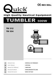
TUMBLER 500W - Quick® SpA
TUMBLER 500W - Quick® SpA
TUMBLER 500W - Quick® SpA
You also want an ePaper? Increase the reach of your titles
YUMPU automatically turns print PDFs into web optimized ePapers that Google loves.
WARNING: before wiring up, be sure the electrical cables are not live.<br />
<strong>TUMBLER</strong> 500 - REV002A<br />
INSTALLATION GB<br />
BEFORE USING THE CAPSTAN READ THESE INSTRUCTIONS CAREFULLY.<br />
IF IN DOUBT, CONTACT YOUR NEAREST “QUICK ® ” DEALER.<br />
WARNING: the Quick ® capstans are designed to weigh engineered for capstan operation.<br />
Do not use the equipment for other purposes.<br />
Quick ® shall not be held responsible for damage to equipment and/or personal injury, caused by a faulty use of the<br />
equipment. The capstan is not designed for the loads that might occur in extreme weather conditions (storms).<br />
Always deactivate the capstan when not in use.<br />
For improved safety we recommend installing at least two anchor capstan controls in case one is accidentally<br />
damaged.<br />
We recommend the use of the Quick ® hydraulic-magnetic switch as the motor safety switch.<br />
The contactor unit or reversing contactor unit must be installed in a point protected from accidental water contact.<br />
THE PACKAGE CONTAINS: capstan - reversing contactor unit - base gasket - handle - bolts and screws (for assembly) - drill<br />
template - user’s manual - conditions of warranty.<br />
TOOLS REQUIRED FOR INSTALLATION: drill and drill bit: Ø 9 mm (23/64") - hollow mill: Ø 50 mm (1"31/32) ;<br />
hexagonal wrenches: 10 mm and 13 mm.<br />
“QUICK ® ”ACCESSORIES RECOMMENDED: anchoring RL control board (mod. 800) - Waterproof hand helds R/C (mod.<br />
HRC1002) - Foot switch (mod. 900) - Hydraulic-magnetic circuit breaker - Radio control RRC (mod. R02, PO2, H02).<br />
ASSEMBLY PROCEDURE: the following parts are to be checked before the holes are drilled. There must be no obstacles<br />
below deck to perform the installation in the lower part. The thickness of deck must be such as to allow the capstan to be<br />
securely placed in position.<br />
max<br />
5 mm<br />
(3/16")<br />
INSTALLATION REQUIREMENTS: Ensure that the upper and lower surfaces of<br />
the deck are as parallel as possible. If this is not the case, compensate the difference<br />
appropriately (a lack of parallelism could result in a loss of motor power). The deck<br />
thickness must be included among the figures listed in the table. In cases of other<br />
thicknesses it is necessary to consult a Quick ® retailer.<br />
ASSEMBLY: when the ideal position has been established, drill four holes using the drilling<br />
template provided. Place the upper part in position and connect it to the bottom part.<br />
Fit the shaft into the gearbox. Fix the capstan by screwing the nuts onto the fixing studs.<br />
Connect the supply cables from the capstan to the reversing contactor unit.<br />
90°<br />
90°<br />
90°<br />
90°<br />
13


