"Membranschalter" Katalog-Download 1,6 MB
"Membranschalter" Katalog-Download 1,6 MB
"Membranschalter" Katalog-Download 1,6 MB

You also want an ePaper? Increase the reach of your titles
YUMPU automatically turns print PDFs into web optimized ePapers that Google loves.
®<br />
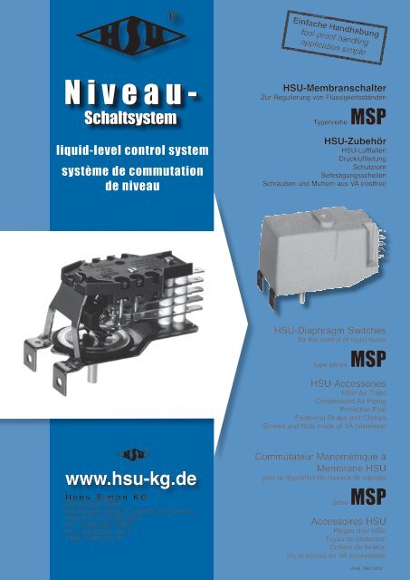
Niveau-<br />
Schaltsystem<br />
liquid-level control system<br />
système de commutation<br />
de niveau<br />
www.hsu-kg.de<br />
®<br />
Hans Simon KG<br />
Elektrotechnische Fabrik<br />
Bruchhausener Straße 13, D-53572 Unkel, Germany<br />
Postfach 0152, D-53568 Unkel<br />
Tel.: ++49 (0) 2224 - 94910<br />
Fax: ++49 (0) 2224 - 2015<br />
e-mail: info@hsu-kg.de<br />
HSU-Membranschalter<br />
Zur Regulierung von Flüssigkeitsständen<br />
Typenreihe MSP<br />
HSU-Zubehör<br />
HSU-Luftfallen<br />
Druckluftleitung<br />
Schutzrohr<br />
Befestigungsschellen<br />
Schrauben und Muttern aus VA (rostfrei)<br />
HSU-Diaphragm Switches<br />
for the control of liquid levels<br />
type series MSP<br />
HSU-Accessories<br />
HSU-Air Traps<br />
Compressed-Air Piping<br />
Protective Pipe<br />
Fastening Straps and Clamps<br />
Screws and Nuts made of VA (stainless)<br />
Commutateur Manométrique à<br />
Membrane HSU<br />
pour la régulation de niveaux de liquides<br />
Série MSP<br />
Accessoires HSU<br />
Pièges d’air HSU<br />
Tuyau de protection<br />
Colliers de fixation<br />
Vis et écrous en VA (inoxydable)<br />
Unkel, März 2012
Eigenschaft<br />
characteristics<br />
attribut<br />
Schaltbereich<br />
control range<br />
plage de commutation<br />
Druckfestigkeit<br />
pressure resistance<br />
résistance à la pression<br />
Druckanschluss<br />
pressure port<br />
raccord de pression<br />
elektrische Schaltleistung<br />
electric switching capacity<br />
puissance de coupure électrique<br />
elektrische Anschlüsse<br />
electric connections<br />
connexions électriques<br />
Bauart<br />
protection mode<br />
mode de protection<br />
Membranschalter zur Regulierung von Flüssigkeitsständen<br />
diaphragm switches (liquid level control system)<br />
commutateurs manométriques à membrane pour la régulation de niveau de liquides<br />
Die Bezeichnung MSP steht für ”Membranschalter<br />
mit Springkontakten”, die als<br />
Wechsler ausgebildet sind. Der Arbeitskontakt<br />
liegt im Ruhezustand am Öffner (O) an.<br />
Wird Luftdruck über eine Luftfalle und flexible,<br />
druckfeste Rohrleitung (Innendurchmesser<br />
5 mm) auf den MSP gebracht, schaltet<br />
der Wechselschalter bei Erreichen eines<br />
eingestellten Umschaltpunktes um.<br />
Die Schaltleistung ist abhängig vom zur<br />
Verfügung stehenden Luftdruck bzw. der<br />
beschaltbaren Wassersäule und den einstellbaren<br />
Umschalt- und Rückschaltpunkten.<br />
Der erste Um-/Einschaltpunkt sollte für 3<br />
A mindestens 10 mbar, dessen Rück-/Ausschaltpunkt<br />
5 mbar betragen.<br />
Für 10 A sollte der Um-/Einschaltpunkt 15<br />
mbar, für den Rück-/Ausschaltpunkt 8 mbar<br />
betragen.<br />
Es sind Schaltdifferenzen zu beachten.<br />
Diese ergeben sich vor Allem aus der temperaturabhängigen<br />
Flexibilität der Membran,<br />
der Trägheit der Umschaltmechanik und der<br />
Adhäsion der zu beschaltbaren Flüssigkeit<br />
und natürlich dem Zustand der Luftfalle und<br />
der Druckluftleitung. Die Umgebungstemperaturdifferenzen<br />
sind von erheblicher Bedeutung.<br />
Die Schaltdifferenzen können bis + 3 mbar<br />
betragen.<br />
MSP-Schalter sind für unterbrochenen<br />
Typenreihe MSP<br />
10 - 100 mbar<br />
< 0,8 bar<br />
Schlauchstutzen<br />
hose connector<br />
manchon<br />
1 - 2 Wechsel-/Springkontakte<br />
1 - 2 changeover contacts/jumpers<br />
1 - 2 contacts inverseurs/contatcts à ressort<br />
1 - 2 Hilfskontakte<br />
1 - 2 auxiliary contacts<br />
1 - 2 contacts auxiliaires<br />
The type designation MSP stands for the<br />
German designation ”Membranschalter mit<br />
Springkontakten”, i.e. diaphragm switch with<br />
jumper plugs, which have been designed as<br />
changeover contacts. In idle state, the make<br />
contact contacts the break contact (O).<br />
If via an air trap and flexible pressure-resistant<br />
piping ( inside dia. 5 mm) air pressure<br />
is applied to the MSP, the changeover switch<br />
switches over as soon as a preset switching<br />
point has been reached.<br />
The switching capacity depends on the<br />
available air pressure resp. on the controllable<br />
water column and the adjustable changeover-<br />
and release positions.<br />
The first changeover/closing-point for 3 A<br />
should be at least 10 mbar, and for the<br />
re lease /switch-OFF point 5 mbar.<br />
In case of 10 A, the changeover/closingpoint<br />
should be 15 mbar, and for the re lease/<br />
switch-OFF point 8 mbar.<br />
Differential gaps must be taken into consideration.<br />
These are due above all to the<br />
temperature-dependent flexibility of the diaphragm,<br />
to the inertia of the changeover<br />
mechanism and to the adhesion of the<br />
liquid to be controlled and, of course, to the<br />
state and condition of the air trap and the<br />
compressed-air piping. The differences in<br />
ambient temperature are of a considerable<br />
significance.<br />
The differential gaps may amount up to +<br />
Die eingestellten Niveaus können in diesem Bereich<br />
überflutet werden<br />
within this range, the set levens might be flooded<br />
les niveaux sélectionnés peuvent être submergés dans<br />
cette plage<br />
5,5 mm<br />
250V AC - 10(3) A<br />
Flachstecker 6,3 x 0,8 aus Stahl verzinnt oder Messing oder Bronze<br />
tabs 0.250“ x 0.03“ of tin-plated steel or brass or bronze<br />
languettes 6,3 x 0,8 en acier étamé ou laiton ou bronze<br />
IP 00<br />
250V AC - 0,5 A oder/or/ou 24V DC - 0,5 A<br />
Les lettres MSP désignent le Commutateur<br />
à Membrane avec Contact à Ressort prévus<br />
comme inverseurs. Le contact de travail est<br />
au repos sur le contact repos (O).<br />
Si de l’air comprimé est amené au MSP par<br />
un piège d’air et un conduit flexible, résistant<br />
à la pression (diamètre interieur 5 mm), le<br />
commutateur change de position lorsqu’un<br />
point de commutation sélectionné est atteint.<br />
La puissance de coupre dépend de la pression<br />
de l’air disponible, c’est-à-dire, de la<br />
colonne d’eau commutable et des points de<br />
commutation et de rétrogradage qui peuvent<br />
être sélectionnnés.<br />
Le premier point de commutation/connexion<br />
devrait être pour 3 A d’au moins 10 mbar,<br />
son point de rétrogradage/déconnexion 5<br />
mbar.<br />
Pour 10 A, le point de commutation/connexion<br />
devrait être de 15 mbar et de 8 mbar<br />
pour le point de rétrogradage/déconnexion.<br />
Il faut respecter les différences de commutation.<br />
Celles-ci proviennent avant tout de<br />
la flexibilité dépendant de la température de<br />
la membrane, de l’intertie du mécanisme de<br />
commutation et de l’adhésion du liquide à<br />
commuter ainsi que, bien sûr, de l’état du<br />
piège d’air et du tuyau d’air comprimé. Les<br />
variations de température ambiente sont<br />
d’une importance non négligeable.<br />
Les différences de commutation peuvent<br />
aller jusqu’à + 3 mbar.<br />
www.hsu-kg.de<br />
2
3 Berieb vorgesehen. Die Luftfalle muß nach<br />
jedem Arbeitszyklus entlüftet werden, mindestens<br />
einmal täglich (siehe Anwendungshinweise<br />
Seite 8).<br />
Der MSP 1 hat einen, der MSP 2 hat zwei<br />
springende Wechselkontakte. Auf jedem<br />
Wechsler kann ein schleichendes Schließerkontaktpaar<br />
betrieben werden, z.B. als<br />
Warngeber (bis 24 V DC oder 250 V AC,<br />
0,5 A) (MSP 2-1 oder MSP 2-2).<br />
Es ist unbedingt erforderlich, vor Inbetriebnahme<br />
die notwendigen Erprobungen und<br />
Festlegungen gewissenhaft vorzunehmen,<br />
vor allem in Bezug auf die elektrische Leistung.<br />
Wir unterscheiden MSP-Schalter mit folgenden<br />
Einstellwerten:<br />
- bis 40 mbar = weiß,<br />
- bis 60 mbar = gelb,<br />
- bis 80 mbar = grün,<br />
- bis 100 mbar = rot.<br />
Die Einstellhöhe für den Überlaufschutzkontakt<br />
sollte jeweils nicht mehr als 30 mbar<br />
über der des höchsteinzustellenden Wechselschalters<br />
liegen.<br />
HSU-Membranschalter dürfen nur in Schaltschränken/Steuerungsgehäusenverwendet<br />
werden. Achtung: frostfrei installieren!<br />
Schaltbilder siehe Seite 5.<br />
Lieferbare Typen:<br />
deliverable types:<br />
exécutions livrables:<br />
MSP 1<br />
MSP 1-1<br />
MSP 2<br />
MSP 2-1<br />
MSP 2-2<br />
Schleichende Hilfskontakte im<br />
Haltestromkreis verwenden.<br />
Slow-action support contacts for<br />
use in a locking circuit.<br />
Contacts rampant de support<br />
seulementuser dans le circuit à<br />
retenir.<br />
www.hsu-kg.de<br />
3 mbar.<br />
MSP-switches have been designed for interrupted<br />
operation. The air trap must be vented<br />
after each operating cycle, at least once<br />
a day (please refer in this respect to page 8).<br />
MSP 1 has got one jumping changeover<br />
contact whilst MSP 2 has got two of them.<br />
One slow-action pair of make contacts can<br />
be operated by each changeover contact,<br />
e.g. as contact for a warning signal (up to<br />
24 V DC or 250 V AC, 0.5 A) (MSP 2-1 or<br />
MSP 2-2).<br />
Before starting operation, it is absolutely<br />
necessary to perform conscientiously the<br />
required tests and adjustments/settings, particularly<br />
with regard to the electric power<br />
output.<br />
The categories of MSP-switches are differentiated<br />
according to the following setting<br />
values:<br />
- up to 40 mbar = white,<br />
- up to 60 mbar = yellow,<br />
- up to 80 mbar = green,<br />
- up to 100mbar = red.<br />
The setting level for the overflow protection<br />
contact should by no means exceed the<br />
setting level of the maximum adjustable<br />
change over switch by more than 30 mbar.<br />
HSU-diahragm switches must only be used<br />
in switch-/control cabinets. Care for frostproof<br />
installation!<br />
Circuit diagramms see page 5.<br />
Les commutateurs MSP sont prévus pour<br />
une utilisation non continue. Le piège d’air<br />
doit être purgé après chaque cycle de travail<br />
une fois chaque jour (voir instructions sur<br />
page 8).<br />
Le MSP 1 possède un contact inverseur, le<br />
MSP 2 en possède deux. Sur chaque inverseur<br />
peut être actionné un couple de contact<br />
de fermeture rampant, par exemple, comme<br />
indicateur d’alerte (jusqu’à 24 V CC ou 250<br />
V CA, 0,5 A) (MSP 2-1 ou MSP 2-2).<br />
Il est absolument indispensable de procéder<br />
conscieusement avant la mise en service<br />
aux test et aux sélections requis, surtout par<br />
rapport à la puissance électrique.<br />
Nous distinguons de commutateurs manométrique<br />
à membrane MSP avec les valeurs<br />
de consigne suivantes:<br />
- jusqu’à 40 mbar = blanc,<br />
- jusqu’à 60 mbar = jaune,<br />
- jusqu’à 80 mbar = vert,<br />
- jusqu’à 100 mbar = rouge.<br />
Le niveau de réglage des contacts de protection<br />
contre le dépassement de capacité<br />
ne devait pas être supérieur de plus de 30<br />
mbar du niveau de consigne maximal de<br />
l’interrupteur va-et-vient.<br />
Les commutateurs à membrane HSU ne<br />
peuvent être utilisés que dans des armoires<br />
ou boîtiers de commandes. Attention: installer<br />
en protégeant du gel!<br />
Diagrammes de circuits voir page 5.<br />
Fragebogen für Membranschalter. Bitte Kopie ausgefüllt an uns zurücksenden!<br />
Questionnaire for diaphragm switches. Please return a copy of the completed questionnaire to us!<br />
Questionnaire pour commutateur à membrane. Veuillez s.v.p. nous retourner une copie remplie!<br />
springend<br />
jumping<br />
a ressort<br />
schleichend<br />
slow action<br />
rampant<br />
EIN * ON * MARCHE<br />
bei steigendem Niveau<br />
with rising level<br />
à niveau montant<br />
Schaltstellungen<br />
positions<br />
positions contact<br />
AUS * OFF * ARRÊT<br />
bei fallendem Niveau<br />
with falling level<br />
à niveau descendant<br />
Toleranzen (tolerances): + 3 mbar<br />
1 mbar = 10 mm WS (water column/col. d’eau)<br />
Belastung / Ampere<br />
load / Ampere<br />
charge / Ampère<br />
250 V AC - 10 (3) A<br />
250 V AC - 0,5 A<br />
24 V DC - 0,5 A<br />
WS unter 5 mbar gelten als nicht sicher beschaltbar!<br />
Water columns below 5 mbar are deeemed to be insecure in switching!<br />
Les valeurs de colonne d’eau en dessous de 5 mbar sont considérées comme<br />
incertaines!
MSP: Abmessungen und Niveaueinstellung<br />
dimensions, level adjustment<br />
dimensions, réglage de niveau<br />
Überlaufschutz<br />
rechts drehen = Niveau tiefer<br />
links drehen = Niveau höher<br />
overflow protection<br />
turn to the right = lower level<br />
turn to the left = higher level<br />
protection de débordement<br />
tourner à droite = niveau plus bas<br />
tourner à gauche = niveau plus haut<br />
1. Niveau einschalten<br />
switch ON level 1<br />
1er niveau de mise en marche<br />
2. Niveau einschalten<br />
switch ON level 2<br />
2me niveau de mise en marche<br />
2. Niveau rückschalten<br />
release level 2<br />
2me niveau de coupure<br />
1. Niveau rückschalten<br />
release level 1<br />
1er niveau de coupure<br />
In dieser Ausführung folgende Typen:<br />
In this design the following types:<br />
Dans cette exécution les types suivants:<br />
MSP 1, MSP 1-1,<br />
MSP 2, MSP 2-1, MSP 2-2<br />
Niveaueinstellung<br />
Durch rechtsherum Drehen der Schrauben<br />
werden die Niveaus höher und durch linksherum<br />
Drehen tiefer eingestellt.<br />
Level adjustment<br />
By turning the screws tro the right, the levels<br />
are adjusted higher, by turning to the left lower<br />
levels are adjusted.<br />
Réglage de niveau<br />
En tournant les vis vers la droite vous augmentez<br />
les niveau, en les tournant vers la gauche<br />
vous les baissez.<br />
www.hsu-kg.de<br />
4
5<br />
www.hsu-kg.de<br />
MSP: Schalt- und Steckbilder<br />
circuit diagramms and plugging schemes<br />
diagrammes de circuit et schémas de branchement
Schaltplan für Haltestromkreis<br />
wiring scheme for locking circuit<br />
schéma de circuit à retenir<br />
www.hsu-kg.de<br />
6
7<br />
MSP sind mit Flachsteckzungen 6,3 x 0,8<br />
ausgerüstet.<br />
Eingang: Messing blank.<br />
Ausgang: Stahl verzinnt.<br />
Das Anschließen erfolgt mit Leitungen /<br />
Schaltlitzen, die mit Flachsteckhülsen 6,3 x<br />
0,8 ausgerüstet sein müssen.<br />
Flachsteckhülsen 6,3 x 0,8 werden mit<br />
Anpreßzange oder Anpreßautomat an die<br />
Leiterenden gepreßt und mit Flachsteckhülsenisolationen<br />
(HSU-HIN) isoliert. Für die<br />
Einzelanfertigung wird dies ‘von Hand’ erfolgen<br />
müssen. Für die Serienanfertigung empfehlen<br />
wir den Bezug der fertigen Schaltlitzen.<br />
HSU liefert Verdrahtungen / Schaltlitzen und<br />
Leitungen aus eigener Konfektion.<br />
Bitte fragen Sie an. Nennen Sie uns:<br />
1. Die Schaltleistung in Ampere.<br />
2. Leitungstype, Querschnitt, Farbe und<br />
Länge, sowie das an den Enden anzu-pressende<br />
Kontaktmaterial.<br />
Für den MSP sind Flachsteckhülsen<br />
6,3 x 0,8 erforderlich.<br />
Für die Verbindungen / Anschlüsse an<br />
Ihre Schaltkomponenten, wie Relais,<br />
L-Schütze usw., bestimmen Sie die<br />
gewünschte Ausrüs tung, z.B. Endhülsen,<br />
Ringzungen, Gabelschuhe, Flachstecker<br />
oder Flachsteckhülsen, nach Erfordernis.<br />
Unsere Verkaufsabteilung un ter breitet kurzfristig<br />
unser Angebot.<br />
Bitte beachten Sie:<br />
Für den ordnungsgemäßen Betrieb von<br />
HSU-MSP unter Spannung AC/DC ab 40 V<br />
ist die Verwendung isolierter Flachsteckhülsen<br />
auf den Anschlußenden der Schaltlitzen<br />
und die berührungssichere Unterbringung im<br />
Schaltkasten- / Gehäuse unbedingt Voraussetzung.<br />
www.hsu-kg.de<br />
Der elektrische Anschluß der HSU-Membranschalter MSP<br />
the electrical connection of the HSU-diaphragm switches MSP<br />
la connexion électrique des commutateurs manométriques à membrane HSU types MSP<br />
MSP are equipped with quick connect tabs<br />
6.3 x 0.8.<br />
Input: bright brass.<br />
Output: tin-plated steel.<br />
Connection is made by means of lines/<br />
stranded interconnected wires which must<br />
be equipped with quick connect receptacles<br />
6.3 x 0.8.<br />
By means of clamping tongues or automatic<br />
clamping machines, the receptacles are<br />
pressed onto the conductor ends and insulated<br />
using insulation sleeves for receptacles<br />
(HSU-HIN). For single units, this will have to<br />
be done ‘by hand’. For serial production, we<br />
recommend to purchase stranded interconnected<br />
wires ready for use.<br />
HSU supplies wirings/stranded interconnected<br />
wires and conductors of own production.<br />
Please let us have your enquiries. You<br />
should give us the following information:<br />
1. Switching capacity in Ampere.<br />
2. Type of conductor, cross section, colour<br />
and length as well as the contact material<br />
with which the ends are to be provided with.<br />
MSP requires quick connect receptacles<br />
6.3 x 0.8 .<br />
For connections to your switching components<br />
like relays, L-contactors etc. you can<br />
stupilate the required equipment, e.g. end<br />
sleeves, annular reeds, spade terminals,<br />
quick connect tabs or receptacles according<br />
to requirements.<br />
Our sales department will gladly submit our<br />
offer without delay.<br />
Please note:<br />
For the appropriate operation of HSU-MSP<br />
at a voltage AC/DC from 40 V onwards, you<br />
must use insulated quick connect receptacles<br />
at the connecting ends of the stranded<br />
interconnected wires and the touchproof<br />
arrangement in a control box is a compulsory<br />
prerequisite.<br />
MSP sont dotés de languettes 6,3 x 0,8.<br />
Entrée: laiton brut.<br />
Sortie: acier étamé.<br />
Le raccordement se fait avec des conduites/<br />
fils à brins multiples, lesquelles doivent être<br />
équiés de fastons 6,3 x 0,8.<br />
Les fastons 6,3 x 0,8 sont serrées sur les<br />
extrémités des conduites avec une pince<br />
plate ou un automate de serrage et isolées<br />
avec des isolements pour fastons individuels<br />
(par ex. HSU-HIN). Pour la construction<br />
unique cela doit se faire à la main. Pour la<br />
construction en série, nous recommendons<br />
l’acquisition de fils à brins multiples prêts à<br />
l’emploi.<br />
HSU fourmit des câblages/fils à brins multiples<br />
et conduites de sa propre fabrication.<br />
Nous vous prions de vous renseigner chez<br />
nous. Faîtes nous savoir:<br />
1. La puissance de rupture en Ampère.<br />
2. La type de conduite, section transversale,<br />
couleur et longeur ainsi que le matériel<br />
de contact à serrer aux extrémités.<br />
Pour le MSP des languettes 6,3 x 0,8 sont<br />
nécessaires.<br />
Pour les raccords/connexions à vos composants<br />
tels que relais, contacteurs-interrupteurs,<br />
etc., vous précisez vous-même, selon<br />
votre besoin, l’équipement désiré, par ex.<br />
douilles d’extrémité, lames rondes, godets à<br />
fourche,languettes ou fastons.<br />
Notre service de vente vous fera parvenir à<br />
bref délai notre offre.<br />
Priére faites-y attention:<br />
Pour le service régulier des MSP de HSU<br />
sous tension AC/DC à partir de 40 V,<br />
l’utilisation des fastons isolés sur les extrémités<br />
de fils à brins multiples ainsi que<br />
l’emplacement dans le coffret de commande<br />
et protégé contre tout attouchement est<br />
absolument nécessaire.
HSU-Membranschalter in Abwasserhebeanlagen<br />
HSU-diaphragm switches in sewage pumping stations<br />
commutateurs à membrane HSU dans des systèmes de levage d’eaux usées<br />
A<br />
Empfehlung für Anlagen bis<br />
100 mbar<br />
1. Pumpen stehen auf dem Schachtboden.<br />
2. Luftfalle oder Staurohröffnung 30 bis 50<br />
mm über den Pumpen anordnen, gege-<br />
benenfalls mit HSU-Luftfalle und Befesti-<br />
gungsmaterial.<br />
3. MSP 2 im Schaltkasten bis 30 m vom<br />
Schacht hoch und trocken unterbringen<br />
und über Druckluftleitung DFL 5<br />
ansteuern.<br />
4. Erstes Niveau bei 30 mbar ein,<br />
bei 10 mbar aus.<br />
5. Der Ausschaltung erstes Niveau bei 10<br />
mbar ein Zeitglied nachschalten und so<br />
einstellen, daß die Pumpe so lange nach<br />
läuft, bis Staurohr- oder Luftfallenöffnung<br />
freigepumpt ist.<br />
6. Zweites Niveau für zweite Pumpe bei 50<br />
- 80 mbar ein, bei 30 - 20 mbar aus.<br />
7. Es sollte eine Wechselschaltung instal-<br />
liert werden, damit die Pumpen wechsel-<br />
weise arbeiten können.<br />
Als Alternative empfehlen wir, die Niveauhöhen<br />
für die zweite oder auch die dritte<br />
Pumpe in geringen Niveauhöhendifferenzen<br />
mit Überdeckung der Ausschaltpunkte einzurichten,<br />
damit alle Pumpen möglichst oft,<br />
wenn auch kurzfristig arbeiten.<br />
B<br />
Empfehlung für Anlagen mit<br />
mehr als 100 mbar<br />
Ist Pumparbeit aus mehreren Metern tiefem<br />
Schacht mit hohen Fluten gefordert, schlagen<br />
wir vor, mit zwei Membranschaltern zu<br />
arbeiten, nach folgendem Prinzip:<br />
1. Zweite Luftfalle im Schacht anordnen,<br />
z.B. bei Niveauhöhe 2.500 mm.<br />
2. Zusätzlich zweiten MSP 1-1 in Schaltkas-<br />
ten einbauen/ansteuern, z.B. mit einer<br />
Einstellung 30 mbar ein, 10 mbar aus.<br />
3. Überflutungswarnkontakt auf 40 mbar<br />
einstellen.<br />
Der MSP 1-1 würde dann mit einer Einstellung<br />
30 - 10 mbar und Warnkontakt 40 mbar<br />
benötigt.<br />
Diese Angaben sind unverbindlich und müssen<br />
den örtlichen Gegebenheiten angeglichen<br />
werden.<br />
A<br />
Recommendations for plants<br />
up to 100 mbar<br />
1. The pumps are located on the bottom of<br />
the drainage well.<br />
2. Arrange air trap or opening of pitometer<br />
30 to 50 mm above the pumps. If neces-<br />
sary, with the HSU air trap and fastening<br />
material.<br />
3. MSP 2 to be installed high and dry inside<br />
a control box at a distance of up to 30 m<br />
from the well, and to be controlled via<br />
compressed-air pipe DFL 5.<br />
4. 1st level at 30 mbar ON, at 10 mbar OFF.<br />
5. Connect in series to the switch-OFF of<br />
the first level at 10 mbar a time relay<br />
which is to be set so that the pump con-<br />
tinues to operate until the opening of the<br />
pitotmeter or of the air trap has been<br />
pumped free.<br />
6. 2nd level for second pump at 50 mbar to<br />
80 mbar ON, at 30 mbar to 20 mbar OFF.<br />
7. A two-way cicuit should be installed so<br />
that the pumps can operate alternately.<br />
As an alternative, we recommend to set the<br />
levels for the second or even for the third<br />
pump with moderate differences in levels<br />
and with overlapping of switch-OFF-points in<br />
order to ensure that the pumps are operating<br />
as often as possible even if only for a short<br />
while.<br />
B<br />
Recommendation for plants<br />
with more than 100 mbar<br />
If pumping at high rates is required from a<br />
well of a depth of several meters, we propose<br />
to use two diaphragm switches MSP operating<br />
according to the following principle:<br />
1. Arrange a second air trap in the well, e.g.<br />
at a level of 2,500 mm.<br />
2. Install a second MSP 1-1 in the control<br />
box to be triggered e.g. by a setting<br />
30 mbar ON, 10 mbar OFF.<br />
3. Overflow warning contact setting at<br />
40 mbar.<br />
The MSP 1-1 would then be required with<br />
a setting 30 mbar - 10 mbar and a warning<br />
contact 40 mbar.<br />
This recommendation is given without any<br />
obligation on our part and must be adapted<br />
to the local conditions.<br />
A<br />
Recommandation pour les<br />
systèmes jusqu’à 100 mbar<br />
1. Les pompes se trouvent sur le fond du<br />
puits.<br />
2. Disposer le piège d’air ou l’ouverture du<br />
tube de haussement 30 à 50 mm dessus<br />
des pompes. Le cas échéant avec piège<br />
d’air HSU et matériel de fixation HSU.<br />
3. Installer MSP 2 à sec dans le boîtier de<br />
contrôle jusqu’à 30 m de hauteur du puits<br />
et le commander par le tuyau d’air com-<br />
primé DFL 5.<br />
4. 1er niveau à 30 mbar MARCHE,<br />
à 10 mbar ARRÊT.<br />
5. Faire succéder à la déconnexion du pre-<br />
mier niveau à 10 mbar une temporisation<br />
et la régler de telle sorte que la pompe<br />
continue à tourner jusqu’à ce que l’ouver-<br />
ture du tube de haussement ou du piège<br />
d’air soit purgée.<br />
6. 2me niveau pour seconde pompe à<br />
50 mbar - 80 mbar MARCHE,<br />
à 30 mbar - 20 mbar ARRÊt.<br />
7. Il est recommendé d’installer une circuit à<br />
basculement afin que les pompes puis-<br />
sent fonctionner en alterance.<br />
Nous proposons comme alternative de régler<br />
les niveau de la deuxième et également de<br />
la troisième pompe à une faible différence de<br />
hauteur de niveau avec chevauchement des<br />
points de déconnexion, afin que les pompes<br />
fonctionnent le plus souvent possible, même<br />
si c’est pendant un temps très court.<br />
B<br />
Recommandation pour les<br />
système de plus de 100 mbar<br />
Si un pompage dams un puits de plusieurs<br />
mètres de profondeur vaec de hauts pilier<br />
est necessaire, nous conseillons de travailler<br />
aved deux commutateurs à membrane MSP<br />
selon le principe suivant:<br />
1. Disposer un deuxième piège d’air dams<br />
le puits, par ex. à une hauteur de niveau<br />
de 2.500 mm.<br />
2. Installer/commander en plus un deux-<br />
ième MSP 1-1 dans le boîtier de contrôle,<br />
par ex. avec un réglage<br />
30 mbar MARCHE, 10 mbar ARRÊt.<br />
3. Sélectionner contact alarme de déborde-<br />
ment 40 mbar.<br />
Le MSP 1-1 serait alors requis avec un<br />
réglage de 30 mbar - 10 mbar et un contact<br />
chaud 40 mbar.<br />
Ces indications sont sans engagement et<br />
doivent être adaptées aux conditions sur<br />
site.<br />
www.hsu-kg.de<br />
8
9<br />
Steuerung für 1 bis 2 Pumpen<br />
bis 100 mbar<br />
control for 1 to 2 pumps<br />
up to 100 mbar<br />
contrôle pour 1 à 2 pompes<br />
jusqu’à 100 mbar<br />
Vorfluter<br />
receiving water<br />
pré-déversoir<br />
Anlage<br />
für 1 bis 2 Pumpen<br />
control<br />
for 1 to 2 pumps<br />
contrôle<br />
pour 1 à 2 pompes<br />
www.hsu-kg.de<br />
Zuläufe<br />
feeders<br />
alimentations<br />
Pumpe<br />
Pump<br />
pompe<br />
Pumpen<br />
Pumps<br />
pompes<br />
Steuerungsanordnung mit Membranschaltern und Luftfalle<br />
control configuration with diaphragm switches and air traps<br />
désignation ordre de contrôle avec commutateurs à membrane et piège d’air<br />
Nr. Typ Artikel-Nr.<br />
No. type part-number<br />
no. type référence<br />
1 LF1 990 001 132<br />
LF2 990 002 132<br />
LF3 990 003 132<br />
2 DFLK 990 010 132<br />
3 LS 28 090 028 132<br />
4 DFL 5x7.2 090 015 103<br />
DFL 5x11 090 014 103<br />
5 HLF 990 004 132<br />
6 LFHR 990 005 132<br />
7 LFHS 990 006 132<br />
8 MSP<br />
9 Relais/Schütz/FI<br />
relay/magnetic switch/FI<br />
relais/contacteur/FI<br />
10 Zeitrelais<br />
time relay<br />
relais temporisé<br />
11 Trennschalter<br />
disconnecting switch<br />
interrupteur<br />
12 Anschluß-Leitung<br />
supply cord<br />
tuyau de raccordement<br />
Steuerung für 1 bis x Pumpen<br />
bis 500 mbar<br />
control for 1 to x pumps<br />
up to 500 mbar<br />
contrôle pour 1 à x pompes<br />
jusqu’à 500 mbar<br />
Vorfluter<br />
receiving water<br />
pré-déversoir<br />
Anlage<br />
für 2 bis x Pumpen<br />
control<br />
for 2 to x pumps<br />
contrôle<br />
pour 2 à x pompes
Luftfalle: Abmessungen und Montagearten<br />
air trap: dimensions and fixation possibilities<br />
piège d’air: dimensions et possibilitées de montage<br />
1 - 3 Anschlußnippel ø 5,5 mm<br />
und Luftkammern<br />
1 to 3 connection hoses ø 5.5 mm<br />
and air chambers<br />
1 à 3 raccords de connection ø 5,5 mm<br />
et chambres d’air<br />
VA-Schraube ø 4,5 oder ø 5<br />
screw of stainless steel ø 4.5 or ø 5<br />
vis en acier inoxydable ø 4,5 ou ø 5<br />
flexible Druckleitung DFL 5x7.2 oder DFL 5x11 zum MSP<br />
plexible pressure pipe DFL 5.7.2 or DFL 5x11 to MSP<br />
tuyau de pression flexible DFL 5.7.2 ou DFL 5x11 au MSP<br />
Sicherheitsklemme DFLK<br />
safety clamp DFLK<br />
collier de tuyau DFLK<br />
Luftfalle<br />
air trap<br />
piège d’air<br />
stufenos einstellbar mit LS 28 Rohr<br />
infinitely adjustable when fixed on LS 28 pipe<br />
fixation sans gradation avec tube LS 28<br />
LF1 - 1 Luftkammer 158 cm 3<br />
1 air chamber 158 cm 3<br />
1 chambre d’air 158 cm 3<br />
LF2 - 2 Luftkammern je 74 cm 3<br />
2 air chambers each 74 cm<br />
2 chambres d’air chaque 74 cm 3<br />
LF3 - 3 Luftkammern je 48 cm 3<br />
3 air chambers each 48 cm 3<br />
3 chambres d’air chaque 48 cm 3<br />
auf Betonstein 100x100x60 aufgedübelt<br />
dowel fixed on concrete brick 100x100x60<br />
montage à cheville sur un pierre de béton 100x100x60<br />
Nr. Typ Artikel-Nr.<br />
No. type part-number<br />
no. type référence<br />
1 LF1 990 001 132<br />
LF2 990 002 132<br />
LF3 990 003 132<br />
2 DFLK 990 010 132<br />
3 LS 28 090 028 132<br />
4 DFL 5x7.2 090 015 103<br />
DFL 5x11 090 014 103<br />
5 HLF 990 004 132<br />
6 LFHR 990 005 132<br />
7 LFHS 990 006 132<br />
fest an der Schachtwand<br />
fixed on the well wall<br />
fixé sur le mur du puit<br />
www.hsu-kg.de<br />
10
11<br />
Membranschalter<br />
diaphragm switches<br />
commutateurs à membrane<br />
Luftfallen<br />
air traps<br />
pièges d’air<br />
Druckleitungen<br />
pressure pipes<br />
tuyaux de pression<br />
Befestigungsmaterial<br />
fixation material<br />
matériel de fixation<br />
Rohr<br />
pipe<br />
tube<br />
www.hsu-kg.de<br />
Typ Artikel-Nr. Beschreibung / Lieferumfang<br />
type part-number description/scope of delivery<br />
type référence description/volume de livraison<br />
MSP 1 990 100 861 Standardausführung + standard type + exécution standard<br />
MSP 1-1 990 110 861 Standardausführung + standard type + exécution standard<br />
MSP 2 990 200 861 Standardausführung + standard type + exécution standard<br />
MSP 2-1 990 210 861 Standardausführung + standard type + exécution standard<br />
MSP 2-2 990 220 861 Standardausführung + standard type + exécution standard<br />
Justieren eines Schaltpunktes/je Stellschraube (nicht rabattfähig)<br />
adjustment of a switching point/per screw (no discount)<br />
ajustement d’un point de commutation par boulon de positionnement (hors rabais)<br />
LF 1 090 001 132 Luftfalle aus Hart-PVC zum Anschluß von einem MSP<br />
air trap for connection of one MSP<br />
piège d’air pour la connexion d’un MSP<br />
LF 2 090 002 132 Luftfalle aus Hart-PVC zum Anschluß von zwei MSP<br />
air trap for connection of two MSP<br />
piège d’air pour la connexion de deux MSP<br />
LF 3 090 003 132 Luftfalle aus Hart-PVC zum Anschluß von drei MSP<br />
air trap for connection of three MSP<br />
piège d’air pour la connexion de trois MSP<br />
DFL 5x7.2 090 015 103 flexible Druckleitung, druckfest 40 bar, per m oder per Rolle à 50 m<br />
flexible pressure pipe, pressure proof 40 bar, per meter or per roll of 50 m each<br />
tuyau de pression flexible, charge de pression 40 bar, par m ou par rouleau à 50 m<br />
DFL 5x11 090 014 103 flexible Druckleitung, druckfest 20 bar, per m oder per Rolle à 50 m<br />
flexible pressure pipe, pressure proof 20 bar, per meter or per roll of 50 m each<br />
tuyau de pression flexible, charge de pression 20 bar, par m ou par rouleau à 50 m<br />
DFLK 990 010 132 zum Festklemmen der Druckleitung DFL 5x7.2 an die Luftfalle:<br />
1 Konusklemme, 1 Druckstück und 2 Schrauben 2,9 x 13<br />
for fixation of the pressure pipe DFL 5x7.2 at the air trap:<br />
1 cone clamp, 1 thrust piece and 2 screws 2.9x13<br />
pour pincer le tuyau de pression DFL 5x7.2 sur le piège d’air:<br />
1 pince conique, 1 pièce de pression et 2 vis 2.9x13<br />
HSU-Niveauschaltsystem * Lieferprogramm<br />
HSU-Liquid Level Control System * Delivery Programme<br />
système de commutation de niveau HSU * Programme de livraison<br />
DFLS 990 016 132 Schlauchschelle 6/16 zum Festklemmen der Druckleitung DFL 5x7.2 oder DFL 5x11 an die Luftfalle<br />
hose clamp 6/16 for fixation of the pressure pipe DFL 5x7.2 or DFL 5x11 at the air trap<br />
collier de tuyau 6/16 pour pincer le tuyau de pression DFL 5x7.2 ou DFL 5x11 sur le piège de l’air<br />
HLF 990 004 132 zur Befestigung der Luftfalle an der Schachtwand mit 2 Schrauben 4,5 x 30 und 2 Dübeln und<br />
zum Befestigen der Luftfalle auf der Halbschelle mit 1 Schraube 4,8 x 19<br />
for fixation of the air trap at the well wall with 2 screws 4.5x30 and 2 dowels, and for fixation of the<br />
air trap at the half-shell clamp using 1 screw 4.8 x 19<br />
pour fixer le piège d’air sur la paroi de la puits avec 2 vis 4,5x30 et 2 chevilles, ainsi que pour fixer<br />
le piège d’air sur le demi collier avec 1 vis 4,8x19<br />
LFHR 990 005 132 für die stufenlos verstellbare Befestigung der Luftfalle am LS 28 Rohr mit<br />
2 Muttern M6, 2 Inbusschrauben M6 x 25<br />
und zum Befestigen der Luftfalle auf der Halbschelle mit 1 Schraube 4,8 x 19<br />
for an infinitely adjustable fixation of the air-trap at LS 28 pipe with 2 nuts M6,<br />
2 hexagon socket screws M6x25 and for fixation of the air trap at the half-shell clamp<br />
using 1 screw 4.8x19<br />
pour la fixation sans gradation du piège d’air sur tube LS 28avec 2 écrous M6, 2 vis à six pans<br />
intérieurs M6x25, ainsi que pour la fixation du piège d’air sur le demi collier avec un vis 4,8x19<br />
LFHS 990 006 132 zur Befestigung des LS 28 Rohres an der Schachtwand mit 2 Muttern M6,<br />
2 Inbusschrauben M6 x 25, 1 Schraube 4,5 x 30 und 1 Dübel S6<br />
for fixation of the LS 28 pipe at the well wall using 2 nuts M6, 2 hexagon socket screws M6x25,<br />
1 screw 4.5x30 and 1 dowel S6<br />
pour la fixation du tube LS 28 à la paroi de la puits avec 2 écrous M6,<br />
2 vis à six pans intérieurs M6x25, 1 vis 4,5x30 et 1 cheville S6<br />
LS 28 090 028 132 Installationsrohr D 28 mm als Isolationsrohr PG 21<br />
in jedem Elektrohandel in Längen von 3 oder 5 m erhältlich<br />
conduit D28 mm as insulation pipe PG21 available in lengths of 3 or 5 m in electrical shops<br />
tube d’installation D28 mm comme tube d’isolation PG21 disponible dans tout commerce d’appareils<br />
électriques dans longeurs de 3 ou 5 m<br />
Alle Schrauben, Muttern und Schlauchschellen sind aus rostfreiem Edelstahl<br />
All screws, nuts and hose clamps are made of stainless steel.<br />
Toutes les vis, écrous et collier de tuyau sont en acier inoxydable.