"Membranschalter" Katalog-Download 1,6 MB
"Membranschalter" Katalog-Download 1,6 MB
"Membranschalter" Katalog-Download 1,6 MB

Create successful ePaper yourself
Turn your PDF publications into a flip-book with our unique Google optimized e-Paper software.
3 Berieb vorgesehen. Die Luftfalle muß nach<br />
jedem Arbeitszyklus entlüftet werden, mindestens<br />
einmal täglich (siehe Anwendungshinweise<br />
Seite 8).<br />
Der MSP 1 hat einen, der MSP 2 hat zwei<br />
springende Wechselkontakte. Auf jedem<br />
Wechsler kann ein schleichendes Schließerkontaktpaar<br />
betrieben werden, z.B. als<br />
Warngeber (bis 24 V DC oder 250 V AC,<br />
0,5 A) (MSP 2-1 oder MSP 2-2).<br />
Es ist unbedingt erforderlich, vor Inbetriebnahme<br />
die notwendigen Erprobungen und<br />
Festlegungen gewissenhaft vorzunehmen,<br />
vor allem in Bezug auf die elektrische Leistung.<br />
Wir unterscheiden MSP-Schalter mit folgenden<br />
Einstellwerten:<br />
- bis 40 mbar = weiß,<br />
- bis 60 mbar = gelb,<br />
- bis 80 mbar = grün,<br />
- bis 100 mbar = rot.<br />
Die Einstellhöhe für den Überlaufschutzkontakt<br />
sollte jeweils nicht mehr als 30 mbar<br />
über der des höchsteinzustellenden Wechselschalters<br />
liegen.<br />
HSU-Membranschalter dürfen nur in Schaltschränken/Steuerungsgehäusenverwendet<br />
werden. Achtung: frostfrei installieren!<br />
Schaltbilder siehe Seite 5.<br />
Lieferbare Typen:<br />
deliverable types:<br />
exécutions livrables:<br />
MSP 1<br />
MSP 1-1<br />
MSP 2<br />
MSP 2-1<br />
MSP 2-2<br />
Schleichende Hilfskontakte im<br />
Haltestromkreis verwenden.<br />
Slow-action support contacts for<br />
use in a locking circuit.<br />
Contacts rampant de support<br />
seulementuser dans le circuit à<br />
retenir.<br />
www.hsu-kg.de<br />
3 mbar.<br />
MSP-switches have been designed for interrupted<br />
operation. The air trap must be vented<br />
after each operating cycle, at least once<br />
a day (please refer in this respect to page 8).<br />
MSP 1 has got one jumping changeover<br />
contact whilst MSP 2 has got two of them.<br />
One slow-action pair of make contacts can<br />
be operated by each changeover contact,<br />
e.g. as contact for a warning signal (up to<br />
24 V DC or 250 V AC, 0.5 A) (MSP 2-1 or<br />
MSP 2-2).<br />
Before starting operation, it is absolutely<br />
necessary to perform conscientiously the<br />
required tests and adjustments/settings, particularly<br />
with regard to the electric power<br />
output.<br />
The categories of MSP-switches are differentiated<br />
according to the following setting<br />
values:<br />
- up to 40 mbar = white,<br />
- up to 60 mbar = yellow,<br />
- up to 80 mbar = green,<br />
- up to 100mbar = red.<br />
The setting level for the overflow protection<br />
contact should by no means exceed the<br />
setting level of the maximum adjustable<br />
change over switch by more than 30 mbar.<br />
HSU-diahragm switches must only be used<br />
in switch-/control cabinets. Care for frostproof<br />
installation!<br />
Circuit diagramms see page 5.<br />
Les commutateurs MSP sont prévus pour<br />
une utilisation non continue. Le piège d’air<br />
doit être purgé après chaque cycle de travail<br />
une fois chaque jour (voir instructions sur<br />
page 8).<br />
Le MSP 1 possède un contact inverseur, le<br />
MSP 2 en possède deux. Sur chaque inverseur<br />
peut être actionné un couple de contact<br />
de fermeture rampant, par exemple, comme<br />
indicateur d’alerte (jusqu’à 24 V CC ou 250<br />
V CA, 0,5 A) (MSP 2-1 ou MSP 2-2).<br />
Il est absolument indispensable de procéder<br />
conscieusement avant la mise en service<br />
aux test et aux sélections requis, surtout par<br />
rapport à la puissance électrique.<br />
Nous distinguons de commutateurs manométrique<br />
à membrane MSP avec les valeurs<br />
de consigne suivantes:<br />
- jusqu’à 40 mbar = blanc,<br />
- jusqu’à 60 mbar = jaune,<br />
- jusqu’à 80 mbar = vert,<br />
- jusqu’à 100 mbar = rouge.<br />
Le niveau de réglage des contacts de protection<br />
contre le dépassement de capacité<br />
ne devait pas être supérieur de plus de 30<br />
mbar du niveau de consigne maximal de<br />
l’interrupteur va-et-vient.<br />
Les commutateurs à membrane HSU ne<br />
peuvent être utilisés que dans des armoires<br />
ou boîtiers de commandes. Attention: installer<br />
en protégeant du gel!<br />
Diagrammes de circuits voir page 5.<br />
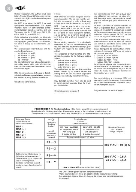
Fragebogen für Membranschalter. Bitte Kopie ausgefüllt an uns zurücksenden!<br />
Questionnaire for diaphragm switches. Please return a copy of the completed questionnaire to us!<br />
Questionnaire pour commutateur à membrane. Veuillez s.v.p. nous retourner une copie remplie!<br />
springend<br />
jumping<br />
a ressort<br />
schleichend<br />
slow action<br />
rampant<br />
EIN * ON * MARCHE<br />
bei steigendem Niveau<br />
with rising level<br />
à niveau montant<br />
Schaltstellungen<br />
positions<br />
positions contact<br />
AUS * OFF * ARRÊT<br />
bei fallendem Niveau<br />
with falling level<br />
à niveau descendant<br />
Toleranzen (tolerances): + 3 mbar<br />
1 mbar = 10 mm WS (water column/col. d’eau)<br />
Belastung / Ampere<br />
load / Ampere<br />
charge / Ampère<br />
250 V AC - 10 (3) A<br />
250 V AC - 0,5 A<br />
24 V DC - 0,5 A<br />
WS unter 5 mbar gelten als nicht sicher beschaltbar!<br />
Water columns below 5 mbar are deeemed to be insecure in switching!<br />
Les valeurs de colonne d’eau en dessous de 5 mbar sont considérées comme<br />
incertaines!