Manuale d'uso Ventilatori Atex - VIP
Manuale d'uso Ventilatori Atex - VIP
Manuale d'uso Ventilatori Atex - VIP

You also want an ePaper? Increase the reach of your titles
YUMPU automatically turns print PDFs into web optimized ePapers that Google loves.
Vip Air Empowerment S.r.l.<br />
Via Einaudi,3 ‐ 20037 Paderno Dugnano (Mi) Italia<br />
Tel +039 029904.8191<br />
Fax +039 029106.397<br />
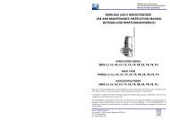
<strong>Manuale</strong> uso e manutenzione<br />
Use and maintenance instruction manual<br />
Betriebs – und Wartungshandbuch<br />
2.3 LABEL DATA<br />
The fan is supplied with a label that identifies the type and its application field; moreover, the motor has its own label, defining<br />
its operating limits, intended as electric data. The fan label does not substitute the motor label<br />
Manufacturer<br />
name and address<br />
Certification body and<br />
certificate no.<br />
3. FAN CHARACTERISTICS<br />
3.1 OPERATING CONDITIONS<br />
Rated operating conditions of <strong>VIP</strong> fans are:<br />
<strong>Atex</strong><br />
Mark<br />
• Continuous duty S1, frequent on/off switching not allowed<br />
• Ambient temperature: ‐20/+40°C<br />
• Atmospheric pressure between 0,8 and 1,1 bar<br />
• Maximum volume fraction of 21% oxygen content<br />
• Clean air<br />
For ambient temperatures different from standard, as well as inconstant duties, the use of specific fans tailored for such<br />
conditions shall be necessary; these shall be specified from the beginning and reported on labels.<br />
3.2 MAXIMUM SPEED<br />
For max rotating velocity, it is intended the synchronous rotating velocity of the motor, calculated according to the number of<br />
the poles of the motor and the rated frequency of the motor power supply<br />
If not differently specified, fan velocity is not adjustable. Any regulation, carried out on the motor supply, in order to exceed the<br />
max velocity, is not allowed.<br />
3.3 AIR TEMPERATURE<br />
The temperature is a basic variable for the proper and reliable use of the fan, the values printed on labesl shall not be exceeded.<br />
If foreseeable hazard rising of temperature exists, the user shall act to apply a device so to prevent dangerous situations.<br />
3.4 BALANCING<br />
The impellers are balanced according to ISO 1940/1‐2003 grade G6.3. Fans shall run with the impeller balanced, anomalous<br />
vibrations, with frequencies equal to the number of blades for the rpm, are signs of unbalance.<br />
3.5 CORROSION RESISTANCE<br />
Fans are not designed to resist to corrosion agents, except specific inquiries in the order<br />
CE Mark Production<br />
batch<br />
Explosion Category and explosion atmosphere Group of gas Temperature class<br />
group 1 zona 0/20 ‐ 2 zona 1/21 ‐ 3 zona 2/22 II A, II B, IIC T1, T2, T3, T4, T5, T6<br />
I (MiG = Gas ‐<br />
D = Dustning)<br />
o T nnn c°<br />
Note: The presence of (X) indicates that the protection grill exceeds the test of mechanical impact with energy of 4 Joule<br />
4. INSTALLATION<br />
The correct installation of the fans avoids further problems during their standard operating. The installation shall not be made in<br />
presence of potentially hazardous atmosphere. Fans shall be grounded; consider that painted parts don’t guarantee an earthing<br />
better than one mega‐Ohm, thus, they are not suitable as components for grounding. Power supply shall be made by skilled<br />
staff, following all the instruction reported on the instruction manual. Fans shall be protected by the entrance of external solid<br />
particles by mean of a system with protection IP 20, at least. If installed in ducts, it’s necessary to consider appropriate<br />
protections according to EN 294 standards. If requested, fans can be provided with drain holes, to be opened in order to make<br />
the moisture get out without damages.<br />
Note: condensing moisture happens when air has a different temperature than the surfaces which is in contact with. Typically,<br />
motor shields and its internal air have different temperatures.<br />
7<br />
4.1 FAN FIXING<br />
Take care of the following points:<br />
Vip Air Empowerment S.r.l.<br />
Via Einaudi,3 ‐ 20037 Paderno Dugnano (Mi) Italia<br />
Tel +039 029904.8191<br />
Fax +039 029106.397<br />
<strong>Manuale</strong> uso e manutenzione<br />
Use and maintenance instruction manual<br />
Betriebs – und Wartungshandbuch<br />
• The fan casing shall be of a substantially rigid design and made in order to avoid the rise of vibrations as well as<br />
resonance phenomena<br />
• All foresee fixing points shall be used<br />
• While tightening bolts, be sure not bend or deform any part of the fan.<br />
• Fix the fan on a flat surface, with no difference in level that makes the fan work in a forced position<br />
In case of assembly of fan with high convoying panel with horizontal axis, either in sucking (Q)or blowing (H)<br />
version, suitable motor shall be considered, since the weight could deform the convoyer and alter the<br />
minimum gap required (see 4.4).<br />
If the fan is connected to a duct, this shall be metallic and antistatic<br />
4.2 FIXING OF FAN WITH PROMINENT IMPELLER<br />
Fans with prominent impeller shall be mounted so that the minimum distance<br />
between the impeller and the other parts of the equipment, where fan is fixed,<br />
shall never be less than 20mm.<br />
4.3 FAN SUPPLY CONNECTION<br />
Mounting, supply connection and set‐up shall be carried out by skilled staff<br />
following the indications printed in the motor manual. In case of motors provided<br />
with thermal protection, their use is strictly recommended, so to avoid further danger. Fix the connection cable of the fan to<br />
prevent danger for tearing. <strong>VIP</strong> technical department is at your disposal to clear doubts<br />
4.4 MINIMUM DISTANCE IMPELLER/CONVOYER (Minimum gap)<br />
The minimum distance between the impeller and still parts shall be calculated according to the following formula:<br />
Gap Minimum = ØImpeller ‐ ØShaft where ØImpeller = Impeller Diameter<br />
100 10 ØShaft = Motor shaft diameter (max 13mm)<br />
However, Gap Minimum shall not be below 2 mm<br />
Example of calculation of Gap Minimum<br />
ØImpeller = 800 mm Gap Minimum = 800 ‐ 19 = 8 – 1,9 = 6,1 mm<br />
ØShaft = 19 mm 100 10<br />
In this case, the impeller shall be distant at least 6,1mm, in the whole circumference, from still parts.<br />
The Gap Minimum permits to calculate the minimum diameter of the conveyer , if used. In fact:<br />
ØMinimum Convoyer = ØImpeller + 2* Gap Minimum In the previous example : ØMinimum Convoyer= 800 + 2* 6,1 = 812,2 mm<br />
4.5 AIR FLOW AND ROTATING DIRECTION<br />
Ceck if impeller runs according to the correct rotating direction and produces an air stream toward the right direction, in<br />
compliance with order<br />
4.6 SAFETY INSTRUCTIONS<br />
<strong>VIP</strong> fans are components of equipments or ventilating sets; they shall operate only after being correctly installed and equipped<br />
with the necessary protections suitable to deny access, also accidentally, to the parts under tension, as well as to the moving<br />
parts.The user shall take care that the equipments, where <strong>VIP</strong> fans are to be installed, respect the safety directives<br />
corresponding to their use and in compliance with the laws of his Country. Each fan shall be provided with a safety switch to cut<br />
off power supply connection.<br />
4.7 ADDITIONAL SAFETY DEVICES FOR DUSTY AMBIENTS<br />
The fans of Group II, Category 2, suitable in atmospheres with presence of dust (2D), shall be provided with a system for the<br />
control of vibrations, which disconnects the fan from the electric supply in case of presence of vibrations potentially hazardous<br />
in compliance with ISO 14694. Such a device shall be neither neutralized nor moved and periodically shall be tested.<br />
8