Manuale d'uso Ventilatori Atex - VIP
Manuale d'uso Ventilatori Atex - VIP
Manuale d'uso Ventilatori Atex - VIP

You also want an ePaper? Increase the reach of your titles
YUMPU automatically turns print PDFs into web optimized ePapers that Google loves.
Vip Air Empowerment S.r.l.<br />
Via Einaudi,3 ‐ 20037 Paderno Dugnano (Mi) Italia<br />
Tel +039 029904.8191<br />
Fax +039 029106.397<br />
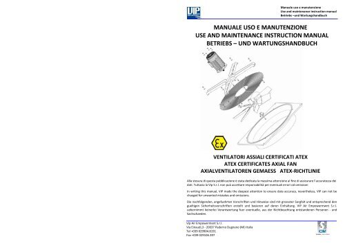
<strong>Manuale</strong> uso e manutenzione<br />
Use and maintenance instruction manual<br />
Betriebs –und Wartungshandbuch<br />
MANUALE USO E MANUTENZIONE<br />
USE AND MAINTENANCE INSTRUCTION MANUAL<br />
BETRIEBS – UND WARTUNGSHANDBUCH<br />
VENTILATORI ASSIALI CERTIFICATI ATEX<br />
ATEX CERTIFICATES AXIAL FAN<br />
AXIALVENTILATOREN GEMAESS ATEX‐RICHTLINIE<br />
Alla stesura di questa pubblicazione è stata dedicata la massima attenzione al fine di assicurare l’accuratezza dei<br />
dati. Tuttavia la Vip S.r.l. non può accettare responsabilità per eventuali errori od omissioni<br />
In writing this manual, <strong>VIP</strong> made the deepest attention to ensure data accuracy, nevertheless, <strong>VIP</strong> can not be<br />
charged for unwanted mistakes and omissions.<br />
Die nachfolgenden, angefuehrten Vorschriften und Hinweise sind mit groesster Sorgfalt und entsprechend den<br />
gueltigen Sicherheitsvorschriften erstellt und basieren auf deren Einhaltung. <strong>VIP</strong> Air Empowermwnt S.r.l.<br />
uebernimmt keinerlei Verantwortung fuer eventuelle, aus der Nichtbeachtung entstandenen Personen ‐ und<br />
Sachschaeden.
Italiano<br />
Vip Air Empowerment S.r.l.<br />
Via Einaudi,3 ‐ 20037 Paderno Dugnano (Mi) Italia<br />
Tel +039 029904.8191<br />
Fax +039 029106.397<br />
<strong>Manuale</strong> uso e manutenzione<br />
Use and maintenance instruction manual<br />
Betriebs – und Wartungshandbuch<br />
1. INTRODUZIONE ............................................................................................................... 2<br />
2. RICEVIMENTO ED ISPEZIONE ...................................................................................... 2<br />
3. CARATTERISTICHE DEL VENTILATORE ................................................................... 3<br />
4. INSTALLAZIONE ............................................................................................................. 3<br />
5. MANUTENZIONE ............................................................................................................. 5<br />
6. GARANZIA ........................................................................................................................ 5<br />
English<br />
1. INTRODUCTION ............................................................................................................... 6<br />
2. RECEIVING AND INSPECTION ...................................................................................... 6<br />
3. FAN CHARACTERISTICS ................................................................................................ 7<br />
4. INSTALLATION ................................................................................................................ 7<br />
5. MAINTENANCE ................................................................................................................ 9<br />
6. GUARANTEE .................................................................................................................... 9<br />
Deutsch<br />
1. EINLEITUNG ................................................................................................................... 10<br />
2. ANLIEFERUNG UND EINGANGSKONTROLLE ........................................................ 10<br />
3. KENNDATEN DES VENTILATORS ............................................................................. 11<br />
4. INSTALLATION .............................................................................................................. 11<br />
5. WARTUNG ...................................................................................................................... 13<br />
6. GARANTIE ...................................................................................................................... 13<br />
1<br />
Vip Air Empowerment S.r.l.<br />
Via Einaudi,3 20037 Paderno Dugnano (Mi), Italy<br />
P.IVA 02100720966<br />
www.vipblade.it<br />
DICHIARAZIONE DI CONFORMITA’<br />
La Vip Air Empowerment S.r.l. dichiara, sotto la propria responsabilità, che i ventilatori assiali della Serie AT<br />
sono conformi ai requisiti della Direttiva 2006/42/CE e alla Direttiva 94/9/CE (ATEX) e possono essere<br />
utilizzati in ambienti ove sia possibile la presenza di atmosfere esplosive in accordo alla classificazione<br />
riportata da EN 1127‐1.<br />
La costruzione dei ventilatori è conforme alle norme standard applicabili qui indicate:<br />
EN 1127‐1, EN13463‐1, EN 149S6:2007<br />
La documentazione tecnica di riferimento del prodotto, come previsto dalla Direttiva 94/9/CE allegato VIII, è<br />
disponibile presso la <strong>VIP</strong> Air Empowerment S.r.l. di via Einaudi, 3 Paderno Dugnano (MI) Italia e per i<br />
ventilatori della categoria 2 la stessa è stata depositata presso l'ente 0080(INERIS) con numero <strong>VIP</strong> 001 :07.<br />
DECLARATION OF CONFORMITY<br />
Vip Air Empowerment S.r.l. declares, under its responsibility, that the axial fans of Range AT complies with<br />
Directive 2006/42/EC and Directive 949/EC (ATEX) requirements and they can be used in zone with the<br />
possible presence of explosive atmospheres according to the classification enclosed in EN 1127‐1 standards.<br />
The construction of the fans is in compliance with the suitable applicable standard norms hereon:<br />
EN 1127‐1, EN13463‐1, EN 14986:2007<br />
The technical documentation of reference of the product, as considered by the Directive 94/9/EC enclosure<br />
VIII, is available at Air Empowerment S.r.l., via Einaudi, 3 Paderno Dugnano (MI) Italy and, for the fans of the<br />
category 2, the same one is filled by the notified corporate body 0080(INERIS) with number <strong>VIP</strong> 001:07.<br />
KONFORMITAETSERKLAERUNG<br />
Die Firma <strong>VIP</strong> Air Empowerment S.r.l. erklaert hiermit unter eigener Verantwortung, dass der Axialventilator<br />
Serie AT konform mit den entsprechenden Richtlinien 2006/42/EG und 94/9/EG (ATEX) sind und in<br />
Umgebungen, wo eine explosive Atmosphaere entstehen kann, im Einklang mit der Norm EN 1127‐1, zum<br />
Einsatz kommen koennen.<br />
Die Konstruktion des Ventilators ist konform und im Einklang mit den Standard Normen:<br />
EN 1127‐1, EN 13463‐1, EN 14986‐2007<br />
Die das Geraet betreffenden technischen Unterlagen sind gemaess der Richtlinie 94/9/EG Anlage VIII, bei<br />
<strong>VIP</strong> Air Empowerment S.r.l., Via Einaudi 3 , 20037 Paderno Dugnano, hinterlegt. Die fuer die Ventilatoren<br />
der Geraete – Kategorie 2 sind bei dem Zertifizierungsinstitut INERIS (0080), unter der N° <strong>VIP</strong> 001:07<br />
deponiert.<br />
Paderno Dugnano, 14/01/2010 Vip Air Empowerment S.r.l.<br />
Fasolini Fausto<br />
(Direttore Generale)<br />
(Managing Director)<br />
(General Direktor)
Vip Air Empowerment S.r.l.<br />
Via Einaudi,3 ‐ 20037 Paderno Dugnano (Mi) Italia<br />
Tel +039 029904.8191<br />
Fax +039 029106.397<br />
<strong>Manuale</strong> uso e manutenzione<br />
Use and maintenance instruction manual<br />
Betriebs – und Wartungshandbuch<br />
5. WARTUNG<br />
Die Wartung des Ventilators muss von qualifiziertem, besonders geschultem Fachpersonal vorgenommen werden. Alle<br />
Wartungsarbeiten und Kontrollen muessen bei stillstehendem, vom Stromnetz abgenommenen Ventilator und in nicht explosiver<br />
Atmosphaere, durchgefuehrt werden. In den ersten zwei Betriebsstunden des Ventilators sicherstellen, dass keine Vibrationen oder<br />
anomale Geraeusche auftreten und das die Spannungs‐und Stromwerte nicht ueber dem Wert des Motorschildes liegen. Nach den ersten<br />
24 Std. Betriebszeit:<br />
• Ueberpruefen, dass alle Schrauben fest angezogen sind<br />
• Sicherstellen, dass das Laufrad sich frei dreht, nicht am Gehaeuse schleift und fest auf der Welle sitzt.<br />
• Sicherstellen, dass sich keine Fremdkoerper am Laufrad oder im Ventilator festgesetzt haben.<br />
Fuer regelmaessige und ausserordentliche Wartungen des Motors auf das Bedienungshandbuch des Motors Bezug nehmen.<br />
5.1 REGELMAESSIGE WARTUNG<br />
Um einen stoerungsfreien Betrieb des Ventilators sicherzustellen, ist eine regelmaessige Wartung erforderlich. Diese sollte wenigstens<br />
vier mal im Jahr durchgefuehrt werden:<br />
• Geraeusche und Vibrationen ueberpruefen. Anomalien zeigen moegliche Stoerungen an.<br />
• sicherstellen, dass sich am Geraet keine Roststellen gebildet haben.<br />
• saeubern des Geraetes mit etwas Reinigungsmittel ( keine Loesemittel ), eventuelle Verkrustungen vorsichtig am Laufrad<br />
entfernen, ohne die Auswuchtung des Laufrades in Frage zu stellen. Mehr als 2mm Staub ist unzulaessig.<br />
• Verschraubungen ueberpruefen<br />
Unter keinen Umstaenden das Laufrad demontieren , da hiermit die Konformitaet und Garantie des Geraetes erlischt.<br />
6. GARANTIE<br />
1. Die Garantiedauer der <strong>VIP</strong> Ventilatoren betraegt 12 Monate ab Lieferdatum. Die Garantie besitzt fuer alle Teile des<br />
Ventilators, fuer eventuelle Reparaturen und kostenlose Ersatzteile, Gueltigkeit.<br />
2. <strong>VIP</strong> behaelt sich die Pruefung und Kontrolle eines Garantieanspruchs vor.<br />
3. Im Einklang mit der Richtlinie 199/44/EG, gemaess Dekret N°24 ( 2.Februar 2010 ) beschraengt sich die <strong>VIP</strong> Garantie nur auf Ihr<br />
Produkt und nicht auf Anlagenteile.<br />
4. Die Garantiezeit beginnt ab Lieferdatum. Wenn dieses nicht nachgewiesen werden kann, gilt das Fabrikationsdatum.<br />
5. Nach Garantieablauf gehen alle eventuellen Ersatzteil‐und Montagekosten zu Lasten des Kunden.<br />
6. Das Kennzeichnungs‐ bzw. Typenschild ist integriertes Teil des Ventilators. Bei einem Abhandenkommen erlischt automatisch<br />
die Garantiezeit.<br />
7. Die Garantieleistung bezieht sich auf Ersatz und Reparatur Franco werk Vip<br />
8. Folgende Leistungen sind von einem Garantieanspruch ausgeschlossen:<br />
• Kontrollen , Wartungen und Reparaturen auf Grund von normalen Verschleiss.<br />
• Fehlerhafte Montage<br />
• Transport‐ oder Handlingsschaeden, welche nicht bei Erhalt der Sendung reklamiert wurden<br />
• selbst verursachte Schaeden<br />
• falsche oder fehlerhafte Verkabelung am Stromnetz<br />
• durch nicht autorisiertes Personal hervorgerufene Schaeden<br />
• Schaeden durch Vandalismus oder atmosphaerische Einfluesse<br />
• Nichtbeachtung der Sicherheitsbestimmungen<br />
13<br />
Vip Air Empowerment S.r.l.<br />
Via Einaudi,3 ‐ 20037 Paderno Dugnano (Mi) Italia<br />
Tel +039 029904.8191<br />
Fax +039 029106.397<br />
<strong>Manuale</strong> uso e manutenzione<br />
Use and maintenance instruction manual<br />
Betriebs – und Wartungshandbuch<br />
1. INTRODUZIONE<br />
I ventilatori <strong>VIP</strong> sono progettati e costruiti per il convogliare aria o gas simili e non devono essere utilizzati per convogliare<br />
sostanze solide o particelle solide sospese nei fluidi, utilizzi differenti sono impropri, comunque le condizioni di esercizio devono<br />
essere conformi a quelle per cui il ventilatore è stato costruito (voltaggio, collegamento, categoria,etc).<br />
I ventilatori oggetto di questo manuale sono adatti al funzionamento in atmosfere potenzialmente esplosive conformemente<br />
alla direttiva 94/9/CE, gruppo II categoria 2 serie AT e categoria 3 serie VV. È responsabilità dell’acquirente e/o dell’utente di far<br />
eseguire l’istallazione e la manutenzione a personale qualificato, mettendo in atto tutte le procedure di sicurezza necessarie e<br />
richieste dalle leggi, regole e norme in vigore nel paese in cui l’apparecchiatura è messa in funzione. Le indicazioni necessarie al<br />
corretto utilizzo dei ventilatori oggetto di questo manuale, si completano con quanto riportato nel manuale di uso e<br />
manutenzione del motore. I ventilatori assiali serie AT sono macchine per l’uso in zone classificate con presenza di gas / vapori<br />
(zona 1) e polveri combustibili (zona 21), progettate e costruite in accordo alla direttiva ATEX 94/9/CE, gruppo II, categoria 2 GD,<br />
secondo le norme europee EN 1127‐1, EN 13463‐1 ed EN 14986. Tutte le parti elettriche dei ventilatori assiali serie AT sono<br />
conformi alla direttiva ATEX 94/9/CE e idonee al gruppo II, alle zone 1 e 21 (categoria 2 GD), alle sostanze presenti, alla<br />
temperatura superficiale e alla temperatura ambiente. I ventilatori devono essere installati e mantenuti in accordo con le norme<br />
impiantistiche e di manutenzione per ambienti classificati a rischio di esplosione per presenza di gas / vapori e polveri<br />
combustibili (esempio: EN 60079‐14, EN 60079‐17, EN 61241‐14, EN 61241‐17 oppure altre norme/standard nazionali).<br />
2. RICEVIMENTO ED ISPEZIONE<br />
Tutti i prodotti <strong>VIP</strong> sono controllati accuratamente prima della spedizione per assicurare i più elevati standard di qualità.<br />
È responsabilità del destinatario controllare che i ventilatori ricevuti siano conformi a quanto ordinato e non abbiano subito<br />
danni durante il trasporto. Ad accettazione avvenuta, la <strong>VIP</strong> risponderà esclusivamente per quanto previsto nella garanzia<br />
assicurativa negli accordi commerciali. In particolare si raccomanda di eseguire i seguenti controlli:<br />
• Confrontare che i componenti corrispondono per codice, descrizione e tipologia con quanto ordinato.<br />
• Controllare che non vi siano parti danneggiate o mancanti.<br />
• Controllare che non vi siano parti mobili se non quelle progettate per esserlo.<br />
• Verificare che la girante ruoti liberamente senza toccare altre parti del ventilatore, che non presenti segni evidenti di<br />
deformazioni locali e sia ben fissata sull’albero del motore.<br />
• Controllare che le viti di fissaggio siano correttamente serrate.<br />
• I ventilatori devono essere sempre accompagnati dal <strong>Manuale</strong> d’Uso e Manutenzione e dall’etichetta contenente i dati<br />
riportati nel successivo paragrafo.<br />
Nota: in caso di dubbi fare sempre riferimento a quanto indicato sui corrispettivi disegni e cataloghi o contattare i tecnici <strong>VIP</strong>.<br />
2.1 MOVIMENTAZIONE<br />
I ventilatori devono essere movimentati da personale esperto. Un errato trasporto o movimentazione può portare a<br />
danneggiamenti, tra cui i più frequenti sono:<br />
• Deformazione della girante<br />
• Deformazione del supporto del motore.<br />
• Deformazione del convogliatore.<br />
• Danneggiamento del motore e del suo allineamento.<br />
Trasportare i ventilatori con l’imballo originale. Gli equipaggiamenti di movimentazione<br />
devono essere scelti in funzioni del peso e della tipologia (forma, tipo di imballo, ecc..) del<br />
materiale da spostare. I ventilatori forniti privi del convogliatore devono essere sollevati e<br />
posizionati con la massima cura per non deformare la girante. In particolare non dovranno<br />
mai essere sollevati facendo presa sulla girante.<br />
Le unità con convogliatore devono essere movimentate in modo da non deformare il<br />
convogliatore stesso, nel caso di convogliatore a basso profilo la girante può sporgere dal<br />
convogliatore, porre la massima attenzione per non danneggiare le parti mobili. Anche<br />
una piccola deformazione può compromettere l’equilibratura del ventilatore.<br />
2.2 STOCCAGGIO<br />
Tutti i ventilatori sono costruiti per essere tenuti a magazzino nelle seguenti condizioni:<br />
• Temperature massime di stoccaggio: ‐25°C ‐ +65°C ed umidità relativa: minore del 60%<br />
• Adeguatamente protetti contro gli agenti esterni atmosferici (pioggia, neve, ecc..) e mantenuti in un luogo<br />
opportunamente ventilato e riscaldato in modo che non si formi condensa o eccessiva umidità<br />
• Ruotare periodicamente la girante per ridistribuire il grasso all’interno dei cuscinetti prevenendone la corrosione.<br />
• Proteggere le unità da carichi e vibrazioni esterni ed evitare esposizione a sostanze corrosive<br />
2
Vip Air Empowerment S.r.l.<br />
Via Einaudi,3 ‐ 20037 Paderno Dugnano (Mi) Italia<br />
Tel +039 029904.8191<br />
Fax +039 029106.397<br />
<strong>Manuale</strong> uso e manutenzione<br />
Use and maintenance instruction manual<br />
Betriebs – und Wartungshandbuch<br />
2.3 DATI ETICHETTA<br />
Il ventilatore è corredato da un’etichetta che ne identifica il tipo e il campo di applicazione, inoltre il motore è corredato da una<br />
propria etichetta che ne riporta i limiti di funzionamento, intesi come dati elettrici. L’etichetta del ventilatore non sostituisce<br />
quella del motore, ma la integra.<br />
Nome ed indirizzo<br />
costruttore<br />
Gruppo di<br />
Appartenenza<br />
Ente certificatore e numero<br />
certificato<br />
Categoria apparecchiatura<br />
e tipo atmosfera<br />
Sottogruppo di<br />
custodia<br />
Classe di<br />
temperatura<br />
I Miniere 1 zona 0/20 ‐ 2 zona 1/21 ‐ 3 zona 2/22 II A, II B, IIC T1, T2, T3, T4, T5, T6<br />
II Superficie G = Gas ‐ D = Polveri<br />
o T nnn c°<br />
NOTA: L’eventuale (X) Indica che la rete di protezione antintrusione supera il test di impatto meccanico con energia di 4 joule<br />
3. CARATTERISTICHE DEL VENTILATORE<br />
3.1 CONDIZIONI DI FUNZIONAMENTO<br />
Le condizioni standard di funzionamento per i ventilatori <strong>VIP</strong> sono:<br />
Marchio<br />
<strong>Atex</strong><br />
• Ciclo continuo S1, commutazioni troppo frequenti non sono previste<br />
• Temperatura ambiente: ‐ 20° C, + 40° C<br />
• Pressione atmosferica compresa tra gli 0,8 bar e 1,1 bar<br />
• Massimo volume di ossigeno del 21%<br />
• Aria pulita<br />
Marchio CE<br />
Per temperature ambiente diverse da quella standard e per cicli discontinui si dovranno utilizzare ventilatori specifici, tali<br />
condizioni dovranno essere indicate in fase d’ordine e saranno riportate in etichetta. I ventilatori sono adatti al funzionamento<br />
nelle condizioni del gruppo e della categoria riportati sull’etichetta.<br />
3.2 VELOCITA’ MASSIMA<br />
Con massima velocità s’intende la velocità di rotazione di sincronismo del motore, calcolata in base al numero di poli e alla<br />
frequenza nominale di alimentazione del motore. La velocità di rotazione dei ventilatori non è regolabile, se non altrimenti<br />
specificato. Sono improprie regolazioni sull’alimentazione del motore allo scopo di superare la massima velocità di rotazione.<br />
3.3 TEMPERATURA DELL’ARIA<br />
La temperatura è una variabile fondamentale per il corretto e sicuro funzionamento del ventilatore, i valori riportati<br />
sull’etichetta non devono essere superati. Nel caso in cui sussista la possibilità che la temperatura superi i limiti indicati, si deve<br />
installare un controllo che prevenga tale situazione pericolosa.<br />
3.4 RESISTENZA ALLA CORROSIONE<br />
I ventilatori non sono costruiti per resistere ad agenti corrosivi, salvo specifiche richieste all’ordine.<br />
Lotto di<br />
produzione<br />
3.5 EQUILIBRATURA<br />
Le giranti sono equilibrate in conformità alla ISO 1940/1‐1986 grado G6.3. I ventilatori dovranno funzionare con la giranti<br />
equilibrate, vibrazioni anomale sono indice dello stato di non equilibratura del ventilatore.<br />
4. INSTALLAZIONE<br />
La corretta installazione di un ventilatore evita l’insorgere di problemi in fase di utilizzo.<br />
L’istallazione non deve mai essere eseguita in presenza di atmosfera potenzialmente esplosiva. Il ventilatore deve essere<br />
sempre collegato ad un cavo di messa a terra. Le parti verniciate non garantiscono un collegamento elettrico migliore di un MΩ,<br />
pertanto non sono adatte come componenti di collegamenti per la messa a terra. I ventilatori devono essere protetti<br />
dall’ingresso di corpi solidi estranei tramite un sistema con grado di protezione almeno IP20, inoltre se installati in un condotto,<br />
è necessario realizzare le opportune protezioni in accordo alla norma EN 294. I ventilatori possono essere forniti, se richiesto, di<br />
fori scarico condensa. Tali fori dovranno essere aperti in modo che la condensa possa fuoriuscire senza creare danni.<br />
Nota: il fenomeno della condensa si verifica quando l’aria ha una temperatura differente dalla temperatura delle superfici con<br />
cui è a contatto. Tipicamente le calotte del motore e l’aria al suo interno hanno temperature differenti.<br />
3<br />
4.1 MONTAGE DES VENTILATORS<br />
Nachstehendes ist zu beachten:<br />
Vip Air Empowerment S.r.l.<br />
Via Einaudi,3 ‐ 20037 Paderno Dugnano (Mi) Italia<br />
Tel +039 029904.8191<br />
Fax +039 029106.397<br />
<strong>Manuale</strong> uso e manutenzione<br />
Use and maintenance instruction manual<br />
Betriebs – und Wartungshandbuch<br />
• der Ventilator muss so auf einem Grundrahmen oder Fundament montiert werden, um uebermaessige Schwingungen und<br />
dadurch auftretende Schallphaenomaene zu vermeiden.<br />
• die vorgesehenen Befestigungsvorrichtungen verwenden.<br />
• beim anziehen der Befestigungsschrauben keine Teile des Ventilators verbiegen bzw. verformen.<br />
• den Ventilator auf einer planen Oberflaeche befestigen.<br />
Bei einer horizontalen Montage des Ventilators mit Vollduese in der Ausfuehrung , saugend ( Q ) oder<br />
drueckend ( H ) ,sind montageseitig besondere Motorhalterungen vorzusehen, da das Motorgewicht die<br />
Einstroemduese deformieren und damit den notwendigen Gap min negativ beeinflussen kann.<br />
Wo die Ventilatoren an Rohrleitungen montiert werden, ist zu beachten, dass diese aus Metall oder antistatischem<br />
Material sind.<br />
4.2 MONTAGE DER VENTILATOREN MIT VORSTEHENDEM LAUFRAD<br />
Die Ventilatoren mit vorstehendem Laufrad muessen so montiert werden, dass der<br />
Abstand zwischen Laufrad und festen Maschinenteilen ( Dmin ) nicht weniger als 20 mm<br />
betraegt<br />
4.3 ELEKTROANSCHLUSS<br />
Die Verkabelung des Motors an das Stromnetz muss von qualifiziertem Fachpersonal,<br />
gemaess der Motor Bedienungsanleitung ,vorgenommen werden. Im Falle das der Motor<br />
mit Thermokontakten ausgeruestet ist, sind diese zu verwenden, um gefaehrliche<br />
Situationen zu vermeiden. Das elektrische Kabel ist so zu befestigen, dass ein ruckartiges reissen am Kabel keine negativen Auswirkungen<br />
hat. Die Techniker der <strong>VIP</strong> stehen fuer eventuelle Rueckfragen zur Verfuegung.<br />
4.4 Mindestabstand zwischen Laufrad und festen Maschinenteilen<br />
Der Mindestabstand (Gap) wird gemaess nachstehender Formel errechnet:<br />
Gap min. = Ø Laufrad ‐ Ø Welle Ø Laufrad = Laufrad Durchmesser<br />
100 10 Ø Welle = Laufradwelle Durchmesser<br />
Gap min. darf nicht unter 2 mm sein<br />
Kalkulationsbeispiel fuer Gap min.<br />
Ø Laufrad = 800 mm Gap min = 800 – 19 = 8 – 1,9 = 6,1 mm<br />
100 10<br />
Ø Welle = 19 mm<br />
In diesem Fall muss der Abstand zwischen Laufrad und festem Maschinenteil 6,1 mm betragen.<br />
Nachstehende Gap min. Formel erlaubt den Durchmesser einer Einstroemduese wie folgt zu errechnen:<br />
Ø min. Einstrroemduese = Ø Laufrad + 2 x Gap min<br />
Ø min. Einstroemduese = 800+ 2 x 6,1 = 812,2 mm<br />
4.5 LUFT UND LAUFRICHTUNG<br />
Kontrollieren, dass die Laufrichtung des Laufrades korrekt ist und die Luft in die gewuenschte Richtung gefoerdert wird.<br />
4.6 SICHERHEITSBESTIMMUNGEN<br />
Die <strong>VIP</strong> Axialventilatoren sind Komponenten von Lueftunsgeraeten oder Anlagen und duerfen nur in Betrieb genommen werden,<br />
nachdem sie ordnungsgemaess installiert und mit den notwendigen Schutzvorrichtungen, was die elektrische Anlage und die beweglichen<br />
mechanischen Teile angeht, versehen sind. Es liegt in der Verantwortung des Betreibers und des Bedienungspersonals sich an die im<br />
Bestimmungsland gueltigen Sicherheitsvorschriften zur Verhuetung von Arbeitsunfaellen zu halten. Jeder Ventilator muss mit einem<br />
Sicherheitsschalter fuer die Unterbrechung zum Stromnetz ausgeruestet werden.<br />
4.7 ZUSAETZLICHE SICHERHEITSMASSNAHMEN FUER DEN EINSATZ IN BRENNBARER STAUBATMOSPHAERE<br />
Die Ventilatoren der Gruppe II, Kategorie 2, fuer den Einsatz in brennbarer Staubatmosphaere, muessen mit einem Vibrierkontrollsystem<br />
ausgeruestet werden, welches den Ventilator vom Stromnetz trennt, wenn sich gefaehrliche Vibrationen gemaess ISO 14694 einstellen<br />
sollten. Diese Vorrichtung darf in keinem Fall neutralisiert oder versetzt werden und muss in periodischen Intervallen getestet werden.<br />
Diese Vorrichtung kann auf Anfrage von <strong>VIP</strong> geliefert werden.<br />
12
Vip Air Empowerment S.r.l.<br />
Via Einaudi,3 ‐ 20037 Paderno Dugnano (Mi) Italia<br />
Tel +039 029904.8191<br />
Fax +039 029106.397<br />
Untergruppe<br />
Schutzart<br />
II A, II B, IIC<br />
<strong>Manuale</strong> uso e manutenzione<br />
Use and maintenance instruction manual<br />
Betriebs – und Wartungshandbuch<br />
2.3 KENNZEICHNUNGSSCHILDER<br />
Am Ventilator sind Typenschilder angebracht, welche Modell und Einsatzgebiet anzeigen. Ueberdies ist der Motor mit einem eigenen<br />
Typenschild versehen, auf welchem die elektrischen Daten angegeben sind. Das Ventilator Typenschild ersetzt nicht das des Motors<br />
sondern ergaenzt es.<br />
Name und Adresse<br />
des Fabrikanten<br />
Betriebsmittelgrupp<br />
e<br />
I unterirdisch<br />
II ueberirdisch<br />
Zertifizierungs‐institut und<br />
Zulassungsnummeer<br />
Gerätekategorie Atmoshaerentyp<br />
1 zone 0/20<br />
2 zone 1/21 G Gas<br />
3 zone 2/22 D Pulver<br />
<strong>Atex</strong><br />
Zeichen<br />
Temperatur‐klasse<br />
T1, T2, T3, T4, T5, T6<br />
o T nnn c°<br />
Anmerkung: Ein eventuelles X zeigt an, dass das Schutzgitter einen mechanischen Aufschlagtest von 4 Joule bestanden hat.<br />
3. KENNDATEN DES VENTILATORS<br />
3.1 EINSATZZONEN<br />
Standardmaessig sind die <strong>VIP</strong> Ventilatoren in nachstehender Umgebung einsetzbar:<br />
• Arbeitsablauf S1, zu haeufige Schaltungen sind nicht vorgesehen<br />
• Umgebungstemperatur: ‐20°C bis +40°C<br />
• Atmosphaerendruck zwischen 0,8 und 1,1 bar<br />
• Sauerstoffgehalt max. 21%<br />
• Saubere Luft<br />
Die Ventilatoren sind fuer die vorgesehenen Einsatzbereiche, die auf den Kennzeichnungsschildern angegeben werden, ausgelegt und<br />
konstruiert. Bei abweichenden Einsatzbedingungen muessen entsprechende Ventilatoren zum Einsatz kommen.<br />
3.2 HOECHSTDREHZAHL<br />
Unter Hoechstdrehzahl versteht man die synchronische Umdrehungsgeschwindigkeit des Motors, berechnet auf Basis der Pole und<br />
Nominalfrequenz des Motors. Die Drehzahl der Ventilatoren ist nicht regelbar, es sei denn dieses ist bei Auftragserteilung ausdruecklich<br />
festgelegt worden. Regelungen, welche eine Erhoehung der Hoechstdrehzahl zum Ziel haben, sind unzulaessig.<br />
3.3 LUFTTEMPERATUR<br />
Die Temperatur ist eine wesentliche Variable fuer eine korrekte Funktion des Ventilators. Die auf dem Typenschild deklarierten Daten<br />
duerfen nicht ueberschritten werden. Sollte die Gefahr bestehen, dass die Betriebstemperatur die deklarierte uebersteigt, hat der<br />
Betreiber dafuer Sorge zu tragen, das ueber entsprechende Kontrollinstrumente eine gefaehrliche Situation vermieden wird.<br />
3.4 AUSWUCHTUNG<br />
Die Luefterraeder sind gemaess ISO 1940/1‐1986, Grad G 6.3 ausgewuchtet. Anomale Vibrationen, mit der Haeufigkeit gleich der<br />
Schaufelanzahl pro Umdrehung, zeigen an, dass das Laufrad nichtmehr ausgewuchtet ist.<br />
3.5 KORROSIONSBESTAENDIGKEIT<br />
Die Ventilatoren sind nicht fuer den Einsatz in korrosionshaltiger Atmosphaere geeignet.<br />
CE Zeichen<br />
4. INSTALLATION<br />
Eine korrekte Installation des Ventilators verhindert Probleme waehrend des Betriebs. Die Installation darf nicht in einer explosiven<br />
Atmosphaere vorgenommen werden.Der Ventilator muss immer mit einem Erdungskabel verbunden sein. Lackierte Teile sind keine<br />
Garantie fuer eine bessere ,elektrische Verbindung und ersetzen keine funktionstuechtige Erdung. Die Ventilatoren muessen gegen den<br />
Ansaug solider Fremdkoerper geschuetzt sein. Schutzgrad wenigstens IP20 . Sollten sie an Rohrleitungen installiert werden , sind die<br />
Schutzbestimmungen gemaess EN 294 einzuhalten. Die Ventilatoren koennen auf Anfrage mit einem Kondensatabfluss geliefert werden.<br />
Dieser Abfluss muss so geoeffnet werden koennen, dass das Kondenswasser ohne Schaden anzurichten abfliessen kann.<br />
Anmerkung: Kondenswasser entsteht, wenn die Lufttemperatur mit der Oberflaechentemperatur mit welcher sie in Kontakt kommt<br />
differiert. Z.B. die Motorkalotte hat in ihrem Inneren andere Temperaturen als die Umgebungsluft.<br />
11<br />
4.1 FISSAGGIO DEL VENTILATORE<br />
Prestare attenzione ai punti elencati di seguito:<br />
Vip Air Empowerment S.r.l.<br />
Via Einaudi,3 ‐ 20037 Paderno Dugnano (Mi) Italia<br />
Tel +039 029904.8191<br />
Fax +039 029106.397<br />
<strong>Manuale</strong> uso e manutenzione<br />
Use and maintenance instruction manual<br />
Betriebs – und Wartungshandbuch<br />
• Il ventilatore deve essere fissato ad un basamento o ad un telaio rigido e costruito in modo da evitare l’insorgere di<br />
vibrazioni eccessive e fenomeni di risonanza.<br />
• Utilizzare tutti i punti di fissaggio previsti<br />
• Nel serrare le viti di fissaggio, fare attenzione a non piegare o deformare alcuna parte del ventilatore.<br />
• Fissare il ventilatore su un piano, che non abbia dislivelli che costringano il ventilatore ad una posizione forzata.<br />
Nel caso di montaggio con asse orizzontale di un ventilatore con convogliatore ad alto profilo sia in<br />
configurazione aspirante (Q) che premente (H), prevedere opportune strutture di sostegno per il motore, in<br />
quanto il peso potrebbe deformare il convogliatore andando ad alterare il gap minimo necessario (vedi 4.4).<br />
Per ventilatori collegati ad un condotto è necessario che quest’ultimo sia metallico o comunque presentare<br />
caratteristiche antistatiche.<br />
4.2 FISSAGGIO DEI VENTILATORI CON GIRANTE SPORGENTE<br />
I ventilatori con girante sporgente devono essere installati in modo tale che la<br />
distanza minima (Dmin) tra la girante e le parti fisse della macchina su cui vengono<br />
montati non deve essere inferiore a 20 mm.<br />
4.3 ALLACCIAMENTO ELETTRICO DEL VENTILATORE<br />
L’allacciamento del motore alla rete elettrica e la messa in servizio devono essere<br />
eseguiti da personale qualificato per l’operazione seguendo le indicazioni riportate<br />
sul manuale di istruzione del motore. Nel caso in cui motore sia fornito di<br />
termocontatti se ne raccomanda l’uso, onde evitare situazioni di pericolo. Ancorare il cavo elettrico in modo che possa<br />
sopportare eventuali strappi. Il personale tecnico della vip potrà essere contattato per fornire chiarimenti in merito<br />
4.4 DISTANZA MINIMA TRA GIRANTE E PARTI FISSE (Gap minimo)<br />
La distanza minima tra la girante e le parti fisse deve essere calcolata secondo la seguente formula :<br />
Gap minimo = ØGirante ‐ ØAlbero con ØGirante = Diametro girante<br />
100 10 ØAlbero = Diametro albero motore (max 13 mm)<br />
Comunque Gap minimo non deve essere inferiore a 2 mm<br />
Esempio di calcolo di Gap minimo<br />
ØGirante = 800 mm Gap minimo = 800 ‐ 19 = 8 – 1,9 = 6,1 mm<br />
ØAlbero = 19 mm 100 10<br />
In questo caso la girante deve distare almeno 6,1 mm, per tutta la sua circonferenza dalle parti fisse<br />
Il Gap minimo permette di calcolare il diametro minimo del convogliatore, ove presente, infatti :<br />
Øminimo convogliatore = ØGirante + 2* Gap minimo ell’esempio precedente: Øminimo convogliatore = 800 + 2* 6,1 = 812,2 mm<br />
4.5 DIREZIONE DELL’ARIA E SENSO DI ROTAZIONE<br />
Verificare che il senso di rotazione della girante sia corretto e generi il flusso d’aria nella giusta direzione.<br />
4.6 NORME DI SICUREZZA<br />
I ventilatori assiali <strong>VIP</strong> sono componenti per macchine o impianti di ventilazione, essi devono essere messi in funzione solo dopo<br />
essere stati correttamente installati e corredati delle necessarie protezioni atte ad impedire l’accesso, anche accidentale, alle<br />
parti sotto tensione ed alle parti in movimento. È responsabilità del cliente o dell’utilizzatore fare in modo che l’impianto o la<br />
macchina completi del ventilatore <strong>VIP</strong>, rispetti le norme di sicurezza corrispondenti al tipo di utilizzo e vigenti nel paese in cui<br />
verrà installata. Ogni ventilatore deve essere provvisto di un interruttore d’emergenza che permetta di interrompere il<br />
collegamento con la rete elettrica di alimentazione.<br />
4.7 DISPOSITIVI DI SICUREZZA AGGIUNTIVI PER AMBIENTI CON POLVERI<br />
I ventilatori del Gruppo II categoria 2, adatti all’utilizzo in atmosfere con presenza di polvere (2D), devono essere dotati di un<br />
sistema di controllo delle vibrazioni che scolleghi il ventilatore dalla linea di alimentazione elettrica nel caso si manifestino<br />
vibrazioni potenzialmente pericolose conformemente alla ISO 14694. Il dispositivo non deve essere neutralizzato ne spostato<br />
per nessuna ragione e deve essere periodicamente testato. Tale dispositivo può essere fornito su richiesta da <strong>VIP</strong>.<br />
4
5. MANUTENZIONE<br />
Vip Air Empowerment S.r.l.<br />
Via Einaudi,3 ‐ 20037 Paderno Dugnano (Mi) Italia<br />
Tel +039 029904.8191<br />
Fax +039 029106.397<br />
<strong>Manuale</strong> uso e manutenzione<br />
Use and maintenance instruction manual<br />
Betriebs – und Wartungshandbuch<br />
La manutenzione del ventilatore deve essere effettuata da personale esperto ed adeguatamente addestrato. Non iniziare alcuna<br />
operazione di manutenzione e/o controllo senza aver prima scollegato l’apparecchiatura dall’alimentazione elettrica e aver<br />
atteso che le parti in movimento si siano fermate. Non eseguire alcun intervento di manutenzione in presenza di atmosfera<br />
potenzialmente esplosiva. Nelle prime due ore di funzionamento monitorare il ventilatore per assicurarsi che non vi siano<br />
vibrazioni o rumori anomali e che i valori di tensione e corrente assorbita siano corretti o comunque non superiori ai valori di<br />
targa indicati sul motore. Dopo le prime 24 ore di funzionamento:<br />
• Controllare il corretto serraggio delle viti<br />
• Controllare che la girante ruoti liberamente, non sfreghi contro parti fisse e non si muova lungo l’albero.<br />
• Verificare che non vi siano depositi anomali di polveri o altro sul ventilatore<br />
Per la manutenzione ordinaria e straordinaria del motore seguire le indicazioni riportate sul libretto di istruzione dello stesso<br />
5.1 MANUTENZIONE ORDINARIA<br />
Per garantire un corretto funzionamento del ventilatore è necessario eseguire una regolare manutenzione.<br />
Come regola generale, rispettando i limiti di impiego e le normali condizioni operative, eseguire almeno quattro volte l’anno, le<br />
seguenti operazioni:<br />
• Verifica del livello di rumore e vibrazioni: valori anomali sono indice di malfunzionamento dell’unità<br />
• Controllare la presenza di corrosioni nella struttura.<br />
• Pulizia della macchina e soprattutto della girante, al fine di prevenire depositi di polvere che possano essere fonte di<br />
rischio. I depositi di polvere su tutti i componenti non devono superare i 2 mm di spessore.<br />
• Verificare e se fosse necessario ripristinare il corretto serraggio delle viti.<br />
Nota: Durante la pulizia della girante porre attenzione a non compromettere l’equilibratura della stessa.<br />
Non rimuovere la girante per nessun motivo; la rimozione della girante fa decadere la conformità del prodotto alla normativa<br />
di riferimento e qualsiasi garanzia.<br />
6. GARANZIA<br />
1. I <strong>Ventilatori</strong> Vip S.r.l. sono garantiti per 12 mesi dalla data di consegna all’utilizzatore. La garanzia è relativa alla riparazione e/o<br />
sostituzione in forma gratuita dei componenti con “vizi” o difetti di fabbricazione.<br />
2. Vip vincola la concessione della garanzia alla verifica di vizi o difetti dei componenti.<br />
3. In conformità con la direttiva 199/44/CE attuata dal Decreto Legislativo N.24 (2 Febbraio 2002), la garanzia Vip è applicabile<br />
esclusivamente al prodotto non contemplando alcuna parte dell’impianto<br />
4. La data di decorrenza della garanzia sarà relativa al documento fiscale di accompagnamento. In mancanza dello stesso la Vip si<br />
riserva di stabilire la decorrenza dalla data di fabbricazione<br />
5. Scaduti i termini di garanzia, i costi relativi ai ricambi ed alla manodopera necessaria alla riparazione, sono a carico del cliente<br />
6. L’etichettatura è parte integrante del prodotto. La sua mancanza, anche parziale, fa decadere la garanzia.<br />
7. La garanzia è limitata alla riparazione o sostituzione franco nostro Stabilimento<br />
8. La garanzia <strong>VIP</strong> non copre:<br />
• Controlli, manutenzioni, riparazioni dovuti a normale usura<br />
• Installazione errata o non conforme<br />
• Danni da trasporto e/o movimentazione non reclamati all’atto della consegna<br />
• Uso improprio<br />
• Alimentazione elettrica non “prevista” dai dati di targa<br />
• Danni o manipolazioni di personale non autorizzato<br />
• Atti vandalici e danni da agenti atmosferici<br />
• Mancato uso dei dispositivi di sicurezza<br />
5<br />
1. EINLEITUNG<br />
Vip Air Empowerment S.r.l.<br />
Via Einaudi,3 ‐ 20037 Paderno Dugnano (Mi) Italia<br />
Tel +039 029904.8191<br />
Fax +039 029106.397<br />
<strong>Manuale</strong> uso e manutenzione<br />
Use and maintenance instruction manual<br />
Betriebs – und Wartungshandbuch<br />
Die <strong>VIP</strong> Ventilatoren sind fuer die vorgesehenen Einsatzbereiche , Foerderung sauberer Luftmengen entwickelt und konstruiert, und<br />
nicht um solide oder fluessige Fremdkoerper zu foerdern. Jeglicher abweichender Verwendungszweck ist untersagt. Die Ventilatoren, auf<br />
welche dieses Handbuch Bezug nimmt, sind fuer den Einsatz in explosionsgefaehrdeten Einsatzzonen gemaess Richtlinie 94/9/EG , Gruppe<br />
II, Kategorie 2 Serie AT und Kategorie 3 Serie VV, konstruiert. Es liegt in der Verantwortung des Empfaengers bzw. des Benutzers die<br />
Installations‐ und Wartungsarbeiten von qualifizierten Personal unter Beachtung der im Bestimmungsland gueltigen<br />
Unfallverhuetungsvorschriften durchfuehren zu lassen. Die angefuehrten, notwendigen Vorschriften fuer eine korrekte Inbetriebnahme<br />
der Ventilatoren , ergaenzen sich mit denen der Wartungs‐und Betriebsanweisungen der Elektromotoren. Die Axialventilatoren, Serie AT,<br />
sind Geraete fuer den Einsatz in den Einsatzzonen, Zone 1, Vorkommen explosiver Gase und brennbarem Staub, Zone 21. Sie sind<br />
entwickelt und konstruiert nach ATEX‐Richtlinie 94/9/EG, Gruppe II, Kategorie 2 GD, gemaess europaeischer Richtlinie EN 1127‐1,EN<br />
13436‐1 und EN 14986. Alle elektrischen Komponenten der Ventilatorserie AT sind konform der ATEX‐Richtlinie 94/9/EG, Gruppe II, Zone<br />
1 und 21, Kategorie 2 GD , bei Vorkommen von explosiven Stoffen, Oberflaechen‐ und Raumtemperatur. Die Ventilatoren muessen<br />
gemaess der gueltiger Anlagen und Wartungsbestimmungen fuer den Einsatz in Einsatzzonen mit Vorkommen von explosiven Gasen,<br />
Staub und Brennstoffen installiert werden. ( Z.B. EN 60079‐14 , EN 60079‐17, EN 61241‐14, EN 61241‐17 oder anderer nationaler<br />
Vorschriften ).<br />
2. ANLIEFERUNG UND EINGANGSKONTROLLE<br />
Alle <strong>VIP</strong> Geraete sind vor der Auslieferung sorfaeltig getestet und kontolliert worden. Bei der Anlieferung muessenVerpackung und die<br />
gelieferten Geraete auf Unversehrtheit ueberprueft werden. Der Spediteur muss ueber eventuelle Transportschaeden unterrichtet, und<br />
eine entsprechende schriftliche Beanstandung in die Wege geleitet werden. Nachdem die Ware in den Besitz des Empfaengers<br />
uebergegangen ist, antwortet <strong>VIP</strong> ausschliesslich gemaess der gueltigen kommerziellen Garantieerklaerung. Nach dem Empfang und vor<br />
der Inbetriebnahme sind folgende Kontrollen durchzufuehren:<br />
• Sicherstellen, dass die angelieferten Teile, Anzahl, Beschreibung/Typ mit denen in der Auftragsphase festgelegten und denen<br />
im Lieferschein aufgefuehrten, uebereinstimmen.<br />
• Ueberpruefen, dass keine Teile fehlen bzw. beschaedigt sind.<br />
• Ventilator und Fluegelrad auf eventuelle Beschaedigungen ueberpruefen.<br />
• Sicherstellen, dass das Laufrad sich leicht dreht und fest auf der Motorwelle befestigt ist.<br />
• Sicherstellen, dass alle Verschraubungen fest angezogen sind.<br />
• Den Ventilatoren muss das Betriebs‐und Wartungsheft beiliegen und die Typenschilder und Aufkleber muessen die in den<br />
nachstehenden Paragrafen aufgefuehrten technischen Daten aufweisen.<br />
Im Zweifelsfall gelten die <strong>VIP</strong> Katalogdaten und die eventuell erstellter Zeichnungen. Ansonsten sind die <strong>VIP</strong> Techniker anzusprechen.<br />
2.1 HANDLING<br />
Die Ventilatoren muessen von qualifizierten Personal betrieben werden. Unsachgemaesser Transport oder Handling koennen zu<br />
Beschaedigungen fuehren:<br />
• Deformation des Fluegellaufrades<br />
• Deformation des Motorsattels<br />
• Deformation der Einstroemduese<br />
• Beschaedigung des Motors und dessen Ausrichtung<br />
Die Ventilatoren werden in Kartons, auf Paletten oder in Holzverschlaegen geliefert. Nur in<br />
Originalverpackung transportieren! Die Transportmittel und Hebezeuge sind dem zu<br />
transportierenden Artikel anzupassen. Die ohne Einstroemduesen gelieferten Ventilatoren sind<br />
mit groesster Sorgfalt zu bewegen und nur unter Zuhilfenahme der angezeigten Stellen<br />
anzuheben und zu transportieren und duerfen in keinem Fall an den Schaufeln angehoben<br />
werden. Die mit Einstroemduesen gelieferten, ohne das diese Duese sich verzieht. Bei der<br />
Ausfuehrung mit kurzer Einstroemduese, steht das Laufrad leicht vor. Es ist groesste Vorsicht<br />
anzuwenden, um das Laufrad nicht zu beschaedigen. Auch die geringste Beschaedigung kann<br />
die Auswuchtung des Laufrades beeintraechtigen.<br />
2.2 EINLAGERUNG<br />
Alle Ventilatoren koennen unter folgenden Bedingungen gelagert werden:<br />
• Lagerraumtemperatur: ‐25°C bis +25°C<br />
• Relative Luftfeuchte: unter 60%<br />
• Die Ventilatoren muessen gegen atmosphaerische Einfluesse geschuetzt, ( Regen, Schnee usw.) in trockenen, temperierten<br />
und geluefteten Raeumen gelagert werden.<br />
• Periodisches drehen des Laufrades, um die Schmierung der Lager zu aktivieren, damit keine Korrosionsgefahr aufkommt.<br />
• Schutz gegen Lasten und Vibrationen, sowie gegen Korrosionseinfluesse.<br />
10
Vip Air Empowerment S.r.l.<br />
Via Einaudi,3 ‐ 20037 Paderno Dugnano (Mi) Italia<br />
Tel +039 029904.8191<br />
Fax +039 029106.397<br />
<strong>Manuale</strong> uso e manutenzione<br />
Use and maintenance instruction manual<br />
Betriebs – und Wartungshandbuch<br />
5. MAINTENANCE<br />
The fan maintenance shall be made by skilled and trained staff. Do not start any maintenance or control operation before<br />
disconnecting the power supply. All moving parts shall be motionless.<br />
Do not carry out any maintenance operation in presence of potentially explosive atmosphere<br />
The fan shall be monitored for at least two working hours, in order to value the presence of vibrations or anomalous noises and<br />
whether the values of voltage and input current do not exceed the label data.<br />
After the first 24 working hours<br />
• Check the correct locking of bolts<br />
• Check the free movement of the impeller, which shall not rub against the conveyer or move along the motor shaft<br />
• Check the presence of anomalous deposits of dust or whatever else on the fan<br />
5.1 ORDINARY MAINTENANCE<br />
In order to guarantee fan correct operating, a regular maintenance is necessary.<br />
As general rule, on respecting the limits of use and the standard operating conditions, carry out, at least four times in a year, the<br />
following operations:<br />
• Verify levels of noise and vibrations; anomalous values are index of malfunction<br />
• Control the presence of corrosion on the structure<br />
• Clean the machine and, mainly, the impeller; so to avoid dust deposits that can be a source of risk. Dust deposits on all<br />
components shall not exceeds 2 mm in thickness<br />
• Verify and restore the correct locking of bolts<br />
Note: During the cleanness of the impeller, take care to not endanger its balance<br />
In any case, do not remove the impeller; its removal voids its compliance with directive and all warranties<br />
6. GUARANTEE<br />
1. <strong>VIP</strong> fans are guaranteed 12 months from the shipping date. The guarantee is related to the free repair and/or replacement of<br />
components with production defects<br />
2. <strong>VIP</strong> binds the grant of warranty to the verifications of defects of components<br />
3. In compliance with Directive 199/44/CE, decree with the force of law no. 24 (2 February 2002), <strong>VIP</strong> guarantee is applicable<br />
exclusively on its product and not on any part of the equipment.<br />
4. The guarantee starting day is related to the date of the shipping document; this missing, <strong>VIP</strong> reserves the right to establish<br />
the guarantee starting day from the production date<br />
5. Guarantee expired, spare part and repairing costs are on Customer’s charge<br />
6. The label is an integral part of the fan. Its absence, also partial, void the guarantee<br />
7. Goods must be sent to <strong>VIP</strong> free of charge<br />
8. <strong>VIP</strong> guarantee does not encompass:<br />
• Controls, maintenances and repairs due to normal wear<br />
• Wrong or inaccurate installation<br />
• Shipping and/or moving damages not claimed at receiving<br />
• Improper use<br />
• Electric supply not in compliance with the label data<br />
• Damages or tampering by unauthorized staff<br />
• Vandalish actions and damages due to atmospheric agents<br />
• Missed use of safety devices<br />
9<br />
Vip Air Empowerment S.r.l.<br />
Via Einaudi,3 ‐ 20037 Paderno Dugnano (Mi) Italia<br />
Tel +039 029904.8191<br />
Fax +039 029106.397<br />
<strong>Manuale</strong> uso e manutenzione<br />
Use and maintenance instruction manual<br />
Betriebs – und Wartungshandbuch<br />
1. INTRODUCTION<br />
<strong>VIP</strong> fans are designed and produced to convoy air and alike and shall not be used to convoy solid substances or particles<br />
suspended in fluids, nor used in different conditions. Anyway, the working conditions shall be in compliance with those they<br />
were designed and produced for (voltage, connections, category and so forth)<br />
The fans, object of this manual, are suitable to work in potentially explosive environments, in compliance with <strong>Atex</strong> Directive<br />
94/9/CE, group II category 2 series AT and category 3 series VV<br />
It is under the attendant or final user’s responsibility the correct installation, operating and maintenance, by acting with all the<br />
necessary safety steps requested by the present laws, rules or regulations in force in the country where the equipment will<br />
operate. Advices, necessary to the correct use of the items of this manual, complement one another with the motor use and<br />
maintenance manual indications. AT fan series are machines suitable for zones classified with presence of gas/ vapour (zone 1)<br />
and combustible dust (zone 21). They are designed and produced in compliance with <strong>Atex</strong> 94/9/CE directive, group II, category 2<br />
GD, according to the European standards EN‐1127‐1, EN 13463‐1 and EN 14986. All the electric parts of AT fans comply with<br />
<strong>Atex</strong> 94/9/CE directive and qualified to group II, to zone 1 and 21 (category 2 GD), to the existing substances, to the surface and<br />
ambient temperature. Fans shall be installed and maintained according to the plant engineering and maintenance<br />
specifications, related to environments classified against the explosion hazard due to the presence of gas/vapour and<br />
combustible dust (example: EN 60079‐14, EN 60079‐17, EN 61241‐14, EN 61241‐17 or different national standards).<br />
2. RECEIVING AND INSPECTION<br />
Before shipping, all <strong>VIP</strong> products underwent to severe controls to ensure the highest quality levels.<br />
The receiver is responsible to control whether the received goods comply with the order and didn’t suffer any damage in<br />
shipping. After receiving the goods, <strong>VIP</strong> is responsible only for what considered in our commercial guarantee.<br />
The following controls are strictly recommended:<br />
• Control that components correspond in number and typology/description to what stated in order<br />
• Control whether there are missing or damaged parts<br />
• Control whether there are moving part except for those provided<br />
• Verify whether the impeller: rotates freely without touching the other parts of the fan, it does not present local hurts<br />
and be tightly fixed to the motor shaft<br />
• Control whether the fixing screws are correctly locked<br />
• Fans shall be provided with: this manual, their labels and data provided in the next paragraph<br />
Note: in doubt, refer always to what indicated in the corresponding drawings and catalogues or contact our technicians<br />
2.1 MOVING<br />
Fans shall be handled by skilled staff. An incorrect moving or handling may seriously affect fans, bringing to:<br />
• The deformation of the impeller<br />
• The deformation of the motor support<br />
• The deformation of the conveyor<br />
• The deformation of the motor and its alignment<br />
Handle fans with their original packing.<br />
The moving equipments shall be chosen according to the weight and typology of the<br />
materials to be moved (form, kind of package, etc..).<br />
Fans provided with conveyor shall be handled and positioned with the maximum care<br />
so to not deform the impeller. In particular, do never lift fans from the impeller.<br />
Units with the conveyor shall be moved in order to avoid damages to the conveyor itself<br />
Versions with short mouth may have the impeller prominent from the conveyor, take<br />
maximum care to not hurt moving parts. Also a little deformation can effect the fan<br />
balancing.<br />
2.2 STORAGE<br />
All fans are designed to be stored in the following conditions:<br />
• Maximum storage temperatures: –25°C/+65°C<br />
• Relative humidity: less than 60%<br />
• Fans must be adequately protected from outdoor atmospheric agents (rain, snow, etc), stored in conveniently<br />
ventilated place and heated in order to avoid moisture and excessive humidity.<br />
• Periodically turn the impeller in order to redistribute the ball‐bearing grease and avoid corrosion<br />
• Protect goods from external loads and vibrations<br />
• Avoid to expose fans to corrosive substances<br />
6
Vip Air Empowerment S.r.l.<br />
Via Einaudi,3 ‐ 20037 Paderno Dugnano (Mi) Italia<br />
Tel +039 029904.8191<br />
Fax +039 029106.397<br />
<strong>Manuale</strong> uso e manutenzione<br />
Use and maintenance instruction manual<br />
Betriebs – und Wartungshandbuch<br />
2.3 LABEL DATA<br />
The fan is supplied with a label that identifies the type and its application field; moreover, the motor has its own label, defining<br />
its operating limits, intended as electric data. The fan label does not substitute the motor label<br />
Manufacturer<br />
name and address<br />
Certification body and<br />
certificate no.<br />
3. FAN CHARACTERISTICS<br />
3.1 OPERATING CONDITIONS<br />
Rated operating conditions of <strong>VIP</strong> fans are:<br />
<strong>Atex</strong><br />
Mark<br />
• Continuous duty S1, frequent on/off switching not allowed<br />
• Ambient temperature: ‐20/+40°C<br />
• Atmospheric pressure between 0,8 and 1,1 bar<br />
• Maximum volume fraction of 21% oxygen content<br />
• Clean air<br />
For ambient temperatures different from standard, as well as inconstant duties, the use of specific fans tailored for such<br />
conditions shall be necessary; these shall be specified from the beginning and reported on labels.<br />
3.2 MAXIMUM SPEED<br />
For max rotating velocity, it is intended the synchronous rotating velocity of the motor, calculated according to the number of<br />
the poles of the motor and the rated frequency of the motor power supply<br />
If not differently specified, fan velocity is not adjustable. Any regulation, carried out on the motor supply, in order to exceed the<br />
max velocity, is not allowed.<br />
3.3 AIR TEMPERATURE<br />
The temperature is a basic variable for the proper and reliable use of the fan, the values printed on labesl shall not be exceeded.<br />
If foreseeable hazard rising of temperature exists, the user shall act to apply a device so to prevent dangerous situations.<br />
3.4 BALANCING<br />
The impellers are balanced according to ISO 1940/1‐2003 grade G6.3. Fans shall run with the impeller balanced, anomalous<br />
vibrations, with frequencies equal to the number of blades for the rpm, are signs of unbalance.<br />
3.5 CORROSION RESISTANCE<br />
Fans are not designed to resist to corrosion agents, except specific inquiries in the order<br />
CE Mark Production<br />
batch<br />
Explosion Category and explosion atmosphere Group of gas Temperature class<br />
group 1 zona 0/20 ‐ 2 zona 1/21 ‐ 3 zona 2/22 II A, II B, IIC T1, T2, T3, T4, T5, T6<br />
I (MiG = Gas ‐<br />
D = Dustning)<br />
o T nnn c°<br />
Note: The presence of (X) indicates that the protection grill exceeds the test of mechanical impact with energy of 4 Joule<br />
4. INSTALLATION<br />
The correct installation of the fans avoids further problems during their standard operating. The installation shall not be made in<br />
presence of potentially hazardous atmosphere. Fans shall be grounded; consider that painted parts don’t guarantee an earthing<br />
better than one mega‐Ohm, thus, they are not suitable as components for grounding. Power supply shall be made by skilled<br />
staff, following all the instruction reported on the instruction manual. Fans shall be protected by the entrance of external solid<br />
particles by mean of a system with protection IP 20, at least. If installed in ducts, it’s necessary to consider appropriate<br />
protections according to EN 294 standards. If requested, fans can be provided with drain holes, to be opened in order to make<br />
the moisture get out without damages.<br />
Note: condensing moisture happens when air has a different temperature than the surfaces which is in contact with. Typically,<br />
motor shields and its internal air have different temperatures.<br />
7<br />
4.1 FAN FIXING<br />
Take care of the following points:<br />
Vip Air Empowerment S.r.l.<br />
Via Einaudi,3 ‐ 20037 Paderno Dugnano (Mi) Italia<br />
Tel +039 029904.8191<br />
Fax +039 029106.397<br />
<strong>Manuale</strong> uso e manutenzione<br />
Use and maintenance instruction manual<br />
Betriebs – und Wartungshandbuch<br />
• The fan casing shall be of a substantially rigid design and made in order to avoid the rise of vibrations as well as<br />
resonance phenomena<br />
• All foresee fixing points shall be used<br />
• While tightening bolts, be sure not bend or deform any part of the fan.<br />
• Fix the fan on a flat surface, with no difference in level that makes the fan work in a forced position<br />
In case of assembly of fan with high convoying panel with horizontal axis, either in sucking (Q)or blowing (H)<br />
version, suitable motor shall be considered, since the weight could deform the convoyer and alter the<br />
minimum gap required (see 4.4).<br />
If the fan is connected to a duct, this shall be metallic and antistatic<br />
4.2 FIXING OF FAN WITH PROMINENT IMPELLER<br />
Fans with prominent impeller shall be mounted so that the minimum distance<br />
between the impeller and the other parts of the equipment, where fan is fixed,<br />
shall never be less than 20mm.<br />
4.3 FAN SUPPLY CONNECTION<br />
Mounting, supply connection and set‐up shall be carried out by skilled staff<br />
following the indications printed in the motor manual. In case of motors provided<br />
with thermal protection, their use is strictly recommended, so to avoid further danger. Fix the connection cable of the fan to<br />
prevent danger for tearing. <strong>VIP</strong> technical department is at your disposal to clear doubts<br />
4.4 MINIMUM DISTANCE IMPELLER/CONVOYER (Minimum gap)<br />
The minimum distance between the impeller and still parts shall be calculated according to the following formula:<br />
Gap Minimum = ØImpeller ‐ ØShaft where ØImpeller = Impeller Diameter<br />
100 10 ØShaft = Motor shaft diameter (max 13mm)<br />
However, Gap Minimum shall not be below 2 mm<br />
Example of calculation of Gap Minimum<br />
ØImpeller = 800 mm Gap Minimum = 800 ‐ 19 = 8 – 1,9 = 6,1 mm<br />
ØShaft = 19 mm 100 10<br />
In this case, the impeller shall be distant at least 6,1mm, in the whole circumference, from still parts.<br />
The Gap Minimum permits to calculate the minimum diameter of the conveyer , if used. In fact:<br />
ØMinimum Convoyer = ØImpeller + 2* Gap Minimum In the previous example : ØMinimum Convoyer= 800 + 2* 6,1 = 812,2 mm<br />
4.5 AIR FLOW AND ROTATING DIRECTION<br />
Ceck if impeller runs according to the correct rotating direction and produces an air stream toward the right direction, in<br />
compliance with order<br />
4.6 SAFETY INSTRUCTIONS<br />
<strong>VIP</strong> fans are components of equipments or ventilating sets; they shall operate only after being correctly installed and equipped<br />
with the necessary protections suitable to deny access, also accidentally, to the parts under tension, as well as to the moving<br />
parts.The user shall take care that the equipments, where <strong>VIP</strong> fans are to be installed, respect the safety directives<br />
corresponding to their use and in compliance with the laws of his Country. Each fan shall be provided with a safety switch to cut<br />
off power supply connection.<br />
4.7 ADDITIONAL SAFETY DEVICES FOR DUSTY AMBIENTS<br />
The fans of Group II, Category 2, suitable in atmospheres with presence of dust (2D), shall be provided with a system for the<br />
control of vibrations, which disconnects the fan from the electric supply in case of presence of vibrations potentially hazardous<br />
in compliance with ISO 14694. Such a device shall be neither neutralized nor moved and periodically shall be tested.<br />
8