Manuale d'uso Ventilatori Assiali - VIP
Manuale d'uso Ventilatori Assiali - VIP
Manuale d'uso Ventilatori Assiali - VIP

Create successful ePaper yourself
Turn your PDF publications into a flip-book with our unique Google optimized e-Paper software.
Vip Air Empowerment S.r.l.<br />
Via Einaudi,3 ‐ 20037 Paderno Dugnano (Mi) Italia<br />
Tel +039 029904.8191<br />
Fax +039 029106.397<br />
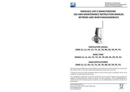
<strong>Manuale</strong> uso e manutenzione<br />
Use and maintenance instruction manual<br />
Betriebs‐und Wartungshandbuch<br />
MANUALE USO E MANUTENZIONE<br />
USE AND MAINTENANCE INSTRUCTION MANUAL<br />
BETRIEBS‐UND WARTUNGSHANDBUCH<br />
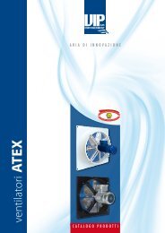
VENTILATORI ASSIALI<br />
SERIE LU, LV, AV, CV, TV, CK, TR, RR, ER, VR, PE, PU<br />
AXIAL FANS<br />
RANGE LU, LV, AV, CV, TV, CK, TR, RR, ER, VR, PE, PU<br />
AXIALVENTILATOREN<br />
SERIE LU, LV, AV, CV, TV, CK, TR, RR, ER, VR, PE, PU<br />
Alla stesura di questa pubblicazione è stata dedicata la massima attenzione al fine di assicurare l’accuratezza dei<br />
dati. Tuttavia la Vip S.r.l. non può accettare responsabilità per eventuali errori od omissioni<br />
In writing this manual, <strong>VIP</strong> made the deepest attention to ensure data accuracy, nevertheless, <strong>VIP</strong> can not be<br />
charged for unwanted mistakes and omissions.<br />
Die nachfolgenden, angefuehrten Vorschriften und Hinweise sind mit groesster Sorgfalt und entsprechend den<br />
gueltigen Sicherheitsvorschriften erstellt und basieren auf deren Einhaltung. <strong>VIP</strong> AIR EMPOWERMENT Srl<br />
uebernimmt keinerlei Verantwortung fuer eventuelle, aus der Nichtbeachtung entstandenen Personen‐und<br />
Sachschaeden.
Italiano<br />
INDICE – INDEX ‐ INALTSANGABE<br />
Vip Air Empowerment S.r.l.<br />
Via Einaudi,3 ‐ 20037 Paderno Dugnano (Mi) Italia<br />
Tel +039 029904.8191<br />
Fax +039 029106.397<br />
<strong>Manuale</strong> uso e manutenzione<br />
Use and maintenance instruction manual<br />
Betriebs‐und Wartungshandbuch<br />
1. CONDIZIONI DI FUNZIONAMENTO ............................................................................. 2<br />
2. RICEVIMENTO ED ISPEZIONE ...................................................................................... 3<br />
3. INSTALLAZIONE ............................................................................................................. 4<br />
4. MESSA IN SERVIZIO ....................................................................................................... 5<br />
5. MANUTENZIONE ............................................................................................................. 5<br />
6. GARANZIA ........................................................................................................................ 5<br />
English<br />
1. OPERATING CONDITIONS ............................................................................................. 6<br />
2. RECEIVING AND INSPECTION ...................................................................................... 7<br />
3. INSTALLATION ................................................................................................................ 8<br />
4. START UP .......................................................................................................................... 9<br />
5. MAINTENANCE ................................................................................................................ 9<br />
6. GUARANTEE .................................................................................................................... 9<br />
Deutsch<br />
1. BETRIEBSBEDINGUNGEN ........................................................................................... 10<br />
2. ANLIEFERUNG UND EINGANGSKONTROLLE ........................................................ 11<br />
3. INSTALLATION .............................................................................................................. 12<br />
4. INBETRIEBNAHME ....................................................................................................... 13<br />
5. WARTUNG ...................................................................................................................... 13<br />
6. GARANTIE ...................................................................................................................... 13<br />
1<br />
Vip Air Empowerment S.r.l.<br />
Via Einaudi,3<br />
20037 Paderno Dugnano (Mi), Italy<br />
P.IVA 02100720966<br />
www.vipblade.it<br />
DICHIARAZIONE DI CONFORMITA’<br />
La Vip Air Empowerment S.r.l. dichiara, sotto la propria responsabilità, che i ventilatori assiali di propria produzione delle serie:<br />
LU, LV, AV, CV, TV, CK, TR, RR, ER, VR, PE, PU<br />
sono conformi ai requisiti essenziali di sicurezza di cui alla Direttiva macchine 2006/42/CE, inoltre risultano conformi alle seguenti<br />
direttive:<br />
• 2006/95/CE (Bassa Tensione)<br />
• 2004/108/CE (Compatibilità Elettromagnetica)<br />
E’ fatto divieto al prodotto oggetto della Dichiarazione di essere messo in servizio prima che la macchina, in cui sarà incorporato o<br />
assiemato, sia stata dichiarata conforme alle disposizioni della Direttiva 2006/42/CE e da quanto indicato nelle norme EN 60204‐1<br />
e UNI EN ISO 12100‐1:2005<br />
DECLARATION OF CONFORMITY<br />
We, the signers of this statement, declare under our own responsibility that all our axial fans, range :<br />
LU, LV, AV, CV, TV, CK, TR, RR, ER, VR, PE, PU<br />
are in compliance with the indispensable safety requirements stated by the Machine Directive 2006/42/EC; furthermore, they<br />
comply with the following directives:<br />
• 2006/95/EC (Low Voltage)<br />
• 2004/108/EC (Electromagnetic compatibility)<br />
It is forbidden to the product covered by of this declaration to be put into service before the machine, where it will be assembled,<br />
has been declared in compliance with Directive 2006/42/CE and as specified in EN 60204‐1 and UNI EN ISO 12100‐1:2005<br />
standards.<br />
KONFORMITAETSERKLAERUNG<br />
Die Firma <strong>VIP</strong> AIR EMPOWERMENT Srl , erklaert hiermit unter alleiniger Verantwortung, dass die Axialventilator der Serie:<br />
LU, LV, AV, CV, TV, CK, TR, RR, ER, VR, PE, PU<br />
konform mit den entsprechenden Maschinenrichtlinien 2006/42/EG sind und ausserdem den nachstehenden Richtlinien<br />
entsprechen:<br />
• 2006/95/ EG ( Niederspannung )<br />
• 2004/108/ EG ( EMV )<br />
Es ist verboten, dass das in dieser Erklaerung benannte Geraet in eine Anlage montiert oder integriert wird, welche nicht der<br />
Richtlinie 2006/42/EG , sowie den Normen EN 60204‐1 und UNI EN ISO 12100‐1: 2005 entspricht.<br />
Paderno Dugnano, 14/01/2010 Vip Air Empowerment S.r.l.<br />
Gestore Fascicolo Tecnico:<br />
Bevollmächtigte Person für das Zusammenstellen der<br />
speziellen Technischen Unterlagen ist:<br />
Responsible technical documentation<br />
Dott. Caimi Paolo<br />
Fasolini Fausto<br />
(Direttore Generale)<br />
(Managing Director)<br />
(General Direktor)
4. INBETRIEBNAHME<br />
Bevor der Ventilator in Betrieb genommen wird, sind folgende Kontrollen durchzufuehren:<br />
Vip Air Empowerment S.r.l.<br />
Via Einaudi,3 ‐ 20037 Paderno Dugnano (Mi) Italia<br />
Tel +039 029904.8191<br />
Fax +039 029106.397<br />
<strong>Manuale</strong> uso e manutenzione<br />
Use and maintenance instruction manual<br />
Betriebs‐und Wartungshandbuch<br />
• Sicherstellen, dass sich keine Fremdkoerper im Laufrad befinden<br />
• Das die Ausrichtung und Position des Ventilator mit den Kondenswasser‐Abflussoeffnungen uebereinstimmen<br />
• Sicherstellen, dass die Verkabelung an das Stromnetz und die Erdung korrekt vorgenommen worden ist<br />
5. WARTUNG<br />
Die Wartung des Ventilators muss von qualifiziertem, besonders geschultem Fachpersonal vorgenommen werden.<br />
Alle Wartungsarbeiten und eventuelle Kontrollen duerfen nur bei stillstehendem, vom Stromnetz<br />
abgenommenen Ventilator und in nicht explosiver Atmosphaere, durchgefuehrt werden<br />
In den ersten zwei Betriebsstunden des Ventilators sicherstellen, dass keine Vibrationen oder anomale<br />
Geraeusche auftreten und das die Spannungs – und Stromwerte korrekt sind und nicht ueber den Werten die auf dem<br />
Motorschild angegeben sind, liegen. Nach den ersten 24 Stunden Betriebszeit :<br />
• Ueberpruefen , dass alle Schrauben fest angezogen sind.<br />
• Sicherstellen , dass das Laufrad sich frei dreht, nicht am Gehaeuse schleift und fest auf der Welle sitzt.<br />
• Sicherstellen, dass sich keine Fremdkoerper am Laufrad oder im Ventilator festgesetzt haben<br />
5.1 REGELMAESSIGE WARTUNG<br />
Um einen stoerungsfreien Betrieb des Ventilators sicherzustellen, ist eine regelmaessige Wartung erforderlich. Diese sollte<br />
wenigstens vier mal im Jahr durchgefuehrt werden:<br />
• Geraeusche und Vibrationen ueberpruefen. Anomalien zeigen moegliche Stoerungen an<br />
• Sicherstellen , dass sich am Geraet keine Roststellen gebildet haben<br />
• Saeubern des Geraetes mit etwas Reinigungsmittel ( keine Loesemittel ) eventuelle Verkrustungen vorsichtig am<br />
Laufrad entfernen. Mehr als 2mm Staub am Geraet ist unzulaessig<br />
• Verschraubungen ueberpruefen<br />
Bemerkung: Waehrend der Reinigungsarbeiten vorsichtig verfahren, ohne die Auswuchtung des Laufrades in Frage zu stellen.<br />
Unter keinen Umstaenden das Laufrad demontieren, da hiermit die Konformitaet und Garantie des Geraetes erlischt.<br />
6. GARANTIE<br />
1. Die Garantiedauer der <strong>VIP</strong> Ventilatoren betraegt 12 Monate ab Lieferdatum. Die Garantie besitzt fuer alle Teile des Ventilators,<br />
fuer eventuelle Reparaturen und kostenlose Ersatzteile , Gueltigkeit.<br />
2. <strong>VIP</strong> behaelt sich die Pruefung und Kontrolle eines Garantieanspruchs vor.<br />
3. Im Einklang mit der Richtlinie 199/44/EG, gemaess Dekret N° 24 ( 2. Februar 2002 ) beschraengt sich die <strong>VIP</strong> Garantie nur auf<br />
ihr Produkt und nicht auf Anlagenteile.<br />
4. Die Garantiezeit beginnt ab Lieferdatum ( Lieferschein ). Wenn dieses nicht nachgewiesen werden kann, gilt das<br />
Fabrikationsdatum.<br />
5. Nach Garantieablauf gehen alle eventuellen Ersatzteil – und Montagekosten zu Lasten des Kunden.<br />
6. Das Kennzeichnungs‐ bzw. Typenschild ist integriertes Teil des Ventilators. Bei einem Abhandenkommen erlischt automatisch<br />
die Garantiezeit.<br />
7. Die Garantieleistung bezieht sich auf Ersatz und Reparatur franco Werk <strong>VIP</strong><br />
8. Folgende Leistungen sind von einem Garantieanspruch ausgeschlossen:<br />
• Kontrollen, Wartungen und Reparaturen auf Grund von normalen Verschleiss<br />
• Fehlerhafte Montage<br />
• Transport‐ oder Handlingsschaeden, welche nicht bei Erhalt der Sendung reklamiert wurden<br />
• Selbst verursachte Schaeden<br />
• Falsche oder fehlerhafte Verkabelung am Stromnetz<br />
• Durch nicht autorisiertes Personal hervorgerufene Schaeden<br />
• Schaeden durch Vandalismus oder atmosphaerische Einfluesse<br />
• Nichtbeachtung der Sicherheitsbestimmungen<br />
13<br />
Vip Air Empowerment S.r.l.<br />
Via Einaudi,3 ‐ 20037 Paderno Dugnano (Mi) Italia<br />
Tel +039 029904.8191<br />
Fax +039 029106.397<br />
<strong>Manuale</strong> uso e manutenzione<br />
Use and maintenance instruction manual<br />
Betriebs‐und Wartungshandbuch<br />
1. CONDIZIONI DI FUNZIONAMENTO<br />
I ventilatori <strong>VIP</strong>, oggetto di questo manuale, sono progettati e costruiti per convogliare aria o gas simili e non<br />
devono essere utilizzati per convogliare sostanze solide o particelle solide sospese nei fluidi, utilizzi differenti<br />
sono impropri. Le condizioni di esercizio devono essere conformi a quelle per cui il ventilatore è stato costruito<br />
(voltaggio, collegamento, categoria,etc), riportate sulla targhetta del ventilatore.<br />
Le condizioni standard di funzionamento per i ventilatori <strong>VIP</strong> sono:<br />
• Atmosfera non potenzialmente esplosiva<br />
• Ciclo continuo S1<br />
• Temperatura ambiente: ‐ 20° C, + 40° C<br />
• Pressione atmosferica compresa tra gli 0,8 bar e 1,1 bar<br />
• Massimo volume di ossigeno del 21%<br />
• Aria pulita<br />
Per condizioni ambientali o cicli di funzionamento diversi da quelle standard si dovranno utilizzare ventilatori specifici, tali<br />
condizioni dovranno essere indicate in fase d’ordine. I ventilatori <strong>VIP</strong>, oggetto di questo manuale, non sono prodotti pronti<br />
all’uso, ma componenti da installare in sistemi più complessi.<br />
1.2 USO CON INVERTER<br />
Un motore alimentato non direttamente da rete ma tramite un convertitore di frequenza (inverter) è sottoposto ad una<br />
alimentazione (tensione, corrente) non puramente sinusoidale che comporta un aumento delle:<br />
• perdite addizionali<br />
• rumore e vibrazioni addizionali<br />
• sollecitazioni dell’isolamento<br />
• condizioni per la formazione di tensioni e correnti nei cuscinetti<br />
Per questo motivo è necessario utilizzare, tra convertitore e motore, filtri sinuosoidali onnipolari ed utilizzare cavi e<br />
collegamenti simmetrici e schermati conformi ai requisiti della 2004/108/CE (EMC) e realizzare una corretta messa a terra del<br />
ventilatore. Le istruzioni addizionali fornite dal costruttore dell’inverter devono essere seguite.<br />
1.3 TEMPERATURA DELL’ARIA<br />
La temperatura è una variabile fondamentale per il corretto e sicuro funzionamento del ventilatore, i valori riportati<br />
sull’etichetta, se presenti, non devono essere superati. Nel caso in cui sussista la possibilità che la temperatura superi i limiti<br />
indicati, si deve installare un controllo di protezione del ventilatore.<br />
1.4 DENSITA’ DELL’ARIA E ALTITUDINE<br />
I dati di utilizzo riportati sulla targhetta del ventilatore si riferiscono all’Atmosfera Standard Internazionale che prevede una<br />
densità dell’aria di ρ = 1,225 Kg/m 3 al livello medio del mare. Variazioni di densità possono provocare variazioni significative<br />
delle prestazioni, solo a titolo indicativo riportiamo un tabella della variazione della densità in funzione dell’altitudine:<br />
Altitudine (geometrica, m) Densità (kg/m³)<br />
0 1,225<br />
500 1,165<br />
1000 1,1117<br />
1500 1,054<br />
2000 1,002<br />
2500 0,952<br />
1.5 RESISTENZA ALLA CORROSIONE<br />
I ventilatori sono costruiti per operare in un'atmosfera gassosa normale, lai presenza di agenti corrosivi particolari va specificata<br />
all’ordine.<br />
1.6 EQUILIBRATURA<br />
Le giranti sono equilibrate in conformità alla ISO 1940/1:2003 grado minimo. I ventilatori dovranno funzionare con le giranti<br />
equilibrate, vibrazioni anomale sono indice dello stato di non equilibratura del ventilatore.<br />
1.7 RUMOROSITA’<br />
I valori di potenza sonora riportati sui cataloghi sono ottenuti in accordo con la EN ISO 3744:2010, tali valori si<br />
riferiscono comunque a condizioni standard e non tengono conto di accessori o situazioni ambientali diverse da<br />
quelle di laboratorio (superfici riflettenti etc). Nel caso in cui il valore di rumorosità superi il valore limite ammesso<br />
dotare gli operatori di opportuni strumenti di protezione (cuffie afonizzanti) e dotare l’area di segnali che ne<br />
raccomandino l’uso o in alternativa dotare il ventilatore di silenziatore.<br />
2
Vip Air Empowerment S.r.l.<br />
Via Einaudi,3 ‐ 20037 Paderno Dugnano (Mi) Italia<br />
Tel +039 029904.8191<br />
Fax +039 029106.397<br />
<strong>Manuale</strong> uso e manutenzione<br />
Use and maintenance instruction manual<br />
Betriebs‐und Wartungshandbuch<br />
2. RICEVIMENTO ED ISPEZIONE<br />
Tutti i prodotti <strong>VIP</strong> sono controllati accuratamente prima della spedizione per assicurare i più elevati<br />
standard di qualità.È responsabilità del destinatario controllare che i ventilatori ricevuti siano<br />
conformi a quanto ordinato e non abbiano subito danni durante il trasporto. Ad accettazione<br />
avvenuta, la <strong>VIP</strong> risponderà esclusivamente per quanto previsto nella garanzia assicurativa negli<br />
accordi commerciali. In particolare si raccomanda di eseguire i seguenti controlli:<br />
• Confrontare che i componenti corrispondono per codice, descrizione e tipologia con quanto ordinato.<br />
• Controllare che non vi siano parti danneggiate o mancanti.<br />
• Controllare che non vi siano parti mobili se non quelle progettate per esserlo.<br />
• Verificare che la girante ruoti liberamente senza toccare altre parti del ventilatore, che non presenti segni evidenti di<br />
deformazioni locali e sia ben fissata sull’albero del motore.<br />
• Controllare che le viti di fissaggio siano correttamente serrate.<br />
• I ventilatori devono essere sempre accompagnati dal <strong>Manuale</strong> d’Uso e Manutenzione e dall’etichetta contenente i dati<br />
riportati nel successivo paragrafo.<br />
Nota: in caso di dubbi fare sempre riferimento a quanto indicato sui corrispettivi disegni e cataloghi o contattare i tecnici <strong>VIP</strong>.<br />
2.1 IDENTIFICAZIONE<br />
Il ventilatore è corredato da un’etichetta che ne identifica il tipo e il campo di applicazione, di seguito è riportato un esempio :<br />
1 Monofase<br />
3 Trifase<br />
Corrente<br />
assorbita<br />
e Numero<br />
giri<br />
Classe di isolamento<br />
Tensioni<br />
ammesse<br />
Frequenza<br />
Grado di protezione<br />
Indica la presenza di termocontatti<br />
2.2 MOVIMENTAZIONE<br />
I ventilatori devono essere movimentati da personale esperto. Un errato trasporto o movimentazione può portare a<br />
danneggiamenti, tra cui i più frequenti sono:<br />
• Deformazione della girante<br />
• Deformazione del supporto del motore<br />
• Deformazione del convogliatore<br />
• Danneggiamento del motore<br />
Potenza<br />
assorbita<br />
Codice Ventilatore<br />
il 4° e 5° carattere identificano la serie<br />
Lotto di<br />
produzione<br />
Trasportare i ventilatori con l’imballo originale. Gli equipaggiamenti di movimentazione<br />
devono essere scelti in funzioni del peso e della tipologia (forma, tipo di imballo, ecc..) del<br />
materiale da spostare. I ventilatori forniti privi del convogliatore devono essere sollevati e<br />
posizionati con la massima cura per non deformare la girante. In particolare non dovranno<br />
mai essere sollevati facendo presa sulla girante.<br />
Le unità con convogliatore devono essere movimentate in modo da non deformare il<br />
convogliatore stesso, nel caso di convogliatore a basso profilo la girante può sporgere dal<br />
convogliatore, porre la massima attenzione per non danneggiare le parti mobili. Anche<br />
una piccola deformazione può compromettere l’equilibratura del ventilatore.<br />
2.3 STOCCAGGIO<br />
Tutti i ventilatori sono costruiti per essere tenuti a magazzino nelle seguenti condizioni:<br />
• Temperature massime di stoccaggio: ‐25°C ‐ +65°C ed umidità relativa: minore del 60%<br />
• Adeguatamente protetti contro gli agenti esterni atmosferici (pioggia, neve, ecc..) e mantenuti in un luogo<br />
opportunamente ventilato e riscaldato in modo che non si formi condensa o eccessiva umidità<br />
• Ruotare periodicamente la girante a salvaguardia dei cuscinetti<br />
• Proteggere le unità da carichi e vibrazioni esterni ed evitare esposizione a sostanze corrosive<br />
3<br />
Vip Air Empowerment S.r.l.<br />
Via Einaudi,3 ‐ 20037 Paderno Dugnano (Mi) Italia<br />
Tel +039 029904.8191<br />
Fax +039 029106.397<br />
<strong>Manuale</strong> uso e manutenzione<br />
Use and maintenance instruction manual<br />
Betriebs‐und Wartungshandbuch<br />
3. INSTALLATION<br />
Eine korrekte Installation des Ventilators verhindert Probleme waehrend des Betriebs . Die Installation darf nicht<br />
in einer explosiven Atmosphaere vorgenommen werden. Der Ventilator muss immer mit einem Erdungskabel<br />
verbunden sein. Lackierte Teile sind keine Garantie fuer eine bessere , elektrische Verbindung und ersetzen keine<br />
funktionstuechtige Erdung. Die Ventilatoren muessen gegen den Ansaug solider Fremdkoerper geschuetzt sein.<br />
Schutzgrad wenigstens IP 20. Sollten sie an Rohrleitungen installiert werden, sind die Schutzbestimmungen<br />
gemaess EN 294 einzuhalten. Die Ventilatoren koennen auf Anfrage mit einem Kondensatabfluss geliefert werden. Dieser<br />
Abfluss muss so geoeffnet werden koennen, dass das Kondenswasser ohne Schaden anzurichten abfliessen kann.<br />
Kondenswasser entsteht, wenn feuchte Luft mit der Oberflaechentemperatur mit der sie in Kontakt kommt differiert.<br />
3.1 MONTAGE DES VENTILATORS<br />
Nachstehendes ist zu beachten:<br />
• der Ventilator muss so auf einem Grundrahmen oder Fundament montiert werden, dass uebermaessige<br />
Schwingungen und dadurch auftretende Schallphaenomaene vermieden werden.<br />
• die vorgesehenen Befestigungsvorrichtungen verwenden<br />
• beim anziehen der Befestigungsschrauben keine Teile des Ventilators verbiegen bzw. verformen<br />
• den Ventilator auf einer planen Oberflaeche befestigen<br />
Wo die Ventilatoren an Rohrleitungen montiert werden, ist zu beachten, das diese aus Metall oder antistatischem Material sind.<br />
3.2 MONTAGE DER VENTILATOREN MIT VORTEHENDEM LAUFRAD<br />
Die Ventilatoren mit vorstehendem Laufrad muessen so montiert werden,<br />
dass der Abstand zwischen Laufrad und festen Maschinenteilen ( Dmin ) nicht<br />
weniger als 20 mm betraegt.<br />
3.3 ELEKTROANSCHLUSS<br />
Die Verkabelung des Motors an das Stromnetz muss von qualifiziertem<br />
Fachpersonal , gemaess der Motor Bedienungsanleitung , vorgenommen<br />
werden. Im Falle das der Motor mit Temperaturwaechtern ausgeruestet ist,<br />
sind diese zu verwenden um den Motor zu schuetzen. Das elektrische Kabel ist so zu befestigen, dass ein ruckartiges Reissen am<br />
Kabel keine negativen Auswirkungen hat. Die Techniker der <strong>VIP</strong> stehen fuer eventuelle Rueckfragen zur Verfuegung.<br />
3.4 MINDESTABSTAND ZWISCHEN LUFRAD UND FESTEN MASCHINENTEILEN<br />
Kontrollieren, dass der Abstand G zwischen Laufrad und<br />
Gehaeuse konstant ist und ein schleifen des Laufrades<br />
Kontrollieren, das die Montageposition des Ventilators<br />
senkrecht zur Laufradachse verlaeuft<br />
3.5 LUFT UND LAUFRICHTUNG<br />
Kontrollieren, dass die Laufrichtung des Laufrades korrekt ist und die Luft in die gewuenschte Richtung gefoerdert wird.<br />
3.6 SICHERHEITSBESTIMMUNGEN<br />
Die <strong>VIP</strong> Axialventilatoren sind Komponenten von Lueftungsgeraeten oder Anlagen und duerfen nur in Betrieb<br />
genommen werden, nachdem sie ordnungsgemaess installiert und mit den notwendigen Schutzvorrichtungen, was die<br />
elektrische Anlage und die beweglichen mechanischen Teile angeht, versehen sind. Es liegt in der Verantwortung des<br />
Betreibers und des Bedienungspersonals sich an die im Bestimmungsland gueltigen Sicherheitsvorschriften zur Verhuetung von<br />
Arbeitsunfaellen zu halten. Jeder Ventilator muss mit einem Sicherheitsschalter fuer die Unterbrechung zum Stromnetz<br />
ausgeruestet werden.<br />
12
Vip Air Empowerment S.r.l.<br />
Via Einaudi,3 ‐ 20037 Paderno Dugnano (Mi) Italia<br />
Tel +039 029904.8191<br />
Fax +039 029106.397<br />
<strong>Manuale</strong> uso e manutenzione<br />
Use and maintenance instruction manual<br />
Betriebs‐und Wartungshandbuch<br />
2. ANLIEFERUNG UND EINGANGSKONTROLLE<br />
Alle <strong>VIP</strong> Geraete sind vor der Auslieferung sorgfaeltig kontrolliert worden, um einen hohen<br />
Qualitaetsstandard zu garantieren. Der Empfaenger hat sich zu vergewissern, dass die gelieferten<br />
Ventilatoren den bestellten entsprechen und waehrend des Transports keine Beschaedigungen<br />
erlitten haben. Der Spediteur muss ueber eventuelle Transportschaeden unterrichtet und eine<br />
entsprechende schriftliche Beanstandung in die Wege geleitet werden. Nachdem die Ware in den Besitz des Empfaengers<br />
uebergegangen ist, antwortet <strong>VIP</strong> ausschliesslich gemaess der gueltigen kommerziellen Garantieerklaerung. Nach dem Empfang<br />
und vor der Inbetriebnahme sind folgende Kontrollen durchzufuehren:<br />
• Sicherstellen, dass die angelieferten Teile, Anzahl, Beschreibung /Typ mit denen in der Auftragsphase festgelegten und<br />
mit denen im Lieferschein aufgefuerhrten uebereinstimmen.<br />
• Ueberpruefen, dass keine Teile fehlen bzw. beschaedigt sind.<br />
• Ventilator und Fluegelrad auf eventuelle Beschaedigungen ueberpruefen.<br />
• Sicherstellen, dass das Laufrad sich leicht dreht und fest auf Motorwelle befestigt ist.<br />
• Sicherstellen, dass alle Verschraubungen fest angezogen sind.<br />
• Den Ventilatoren muss das Betriebs‐und Wartungsheft beiliegen und die Typenschilder muessen die in den<br />
nachstehenden Paragraphen aufgefuehrten technischen Daten aufweisen.<br />
Zweifelsfall gelten die <strong>VIP</strong> Katalogdaten und die eventuell erstellten Zeichnungen. Ansonsten sind die <strong>VIP</strong> Techniker<br />
anzusprechen.<br />
2.1 KENNZEICHNUNGSSCHILDER<br />
Am Ventilator sind Typenschilder angebracht, welche Modell und Einsatzgebiet anzeigen. Siehe Beispiel:<br />
1 Wechselstrom<br />
3 Drehstrom<br />
Stromaufnahme<br />
und Drehzahl<br />
Isolierklasse<br />
zulaessige<br />
Spannung<br />
Frequenz<br />
Schutzgrad<br />
aufgenommene<br />
Leistung<br />
Temperaturwaechter<br />
2.2 HANDLING<br />
Die Ventilatoren muessen von qualifizierten Personal betrieben werden. Unsachgemaesser Transport oder Handling koennen zu<br />
Beschaedigungen fuehren :<br />
• Deformation des Fluegellaufrades<br />
• Deformation des Motorsattels<br />
• Deformation der Einstroemduese<br />
• Beschaedigung des Motors und dessen Ausrichtung<br />
Die Ventilatoren werden in Kartons, auf Paletten oder in Holzverschlaegen geliefert. Nur in Originalverpackung transportieren!<br />
Die Transportmittel und Hebezeuge sind dem zu transportierenden Artikel anzupassen. Die ohne Einstroemduesen gelieferten<br />
Ventilatoren sind mit groesster Sorgfalt zu bewegen und nur unter Zuhilfenahme der angezeigten Stellen anzuheben und zu<br />
transportieren und duerfen in keinem Fall an den Schaufeln angehoben werden.<br />
Die mit Einstroemduese gelieferten Ventilatoren, ohne das die Duese sich verzieht. Bei der Ausfuehrung mit kurzer<br />
Einstroemduese, steht das Laufrad leicht vor. Es ist groesste Vorsicht anzuwenden ,um das Laufrad nicht zu beschaedigen.<br />
Auch die geringste Beschaedigung kann die Auswuchtung des Ventilators beeintraechtigen.<br />
2.2 EINLAGERUNG<br />
Alle Ventilatoren koennen unter folgenden Bedingungen gelagert werden:<br />
Ventilator Code<br />
die 4° und 5° Stelle zeigen die Baureihe an<br />
Produktionslot<br />
• Lagerraumtemperatur: ‐25°C bis +65°C und relative Luftfeuchte unter 60%<br />
• Die Ventilatoren muessen gegen atmoshaerische Einfluesse geschuetzt ( Regen ,Schnee , usw.) in trockenen,<br />
temperierten und geluefteten Raeumen gelagert werden , um Kondensbildung zu vermeiden<br />
• Periodisches drehen des Laufrades, um die Schmierung der Lager zu aktivieren<br />
• Schutz gegen Lasten und Vibrationen, sowie gegen Korrosion<br />
11<br />
Vip Air Empowerment S.r.l.<br />
Via Einaudi,3 ‐ 20037 Paderno Dugnano (Mi) Italia<br />
Tel +039 029904.8191<br />
Fax +039 029106.397<br />
<strong>Manuale</strong> uso e manutenzione<br />
Use and maintenance instruction manual<br />
Betriebs‐und Wartungshandbuch<br />
3. INSTALLAZIONE<br />
La corretta installazione di un ventilatore evita l’insorgere di problemi in fase di utilizzo. L’istallazione non deve<br />
mai essere eseguita in presenza di atmosfera potenzialmente esplosiva. Il ventilatore deve essere sempre<br />
collegato ad un cavo di messa a terra. Le parti verniciate non garantiscono un collegamento elettrico migliore di<br />
un MΩ, pertanto non sono adatte come componenti di collegamenti per la messa a terra. I ventilatori devono<br />
essere protetti dall’ingresso di corpi solidi estranei tramite un sistema con grado di protezione almeno IP20,<br />
inoltre se installati in un condotto, è necessario realizzare le opportune protezioni in accordo alla norma EN 294. I ventilatori<br />
possono essere forniti, se richiesto, di fori scarico condensa. Tali fori dovranno essere aperti in modo che la condensa possa<br />
fuoriuscire senza creare danni.<br />
Nota: il fenomeno della condensa si verifica in presenza di gap termici tra l’aria carica di umidità e le superfici con cui è a<br />
contatto.<br />
3.1 FISSAGGIO DEL VENTILATORE<br />
Prestare attenzione ai punti elencati di seguito:<br />
• Il ventilatore deve essere fissato ad un basamento o ad un telaio rigido e costruito in modo da evitare l’insorgere di<br />
vibrazioni eccessive e fenomeni di risonanza.<br />
• Utilizzare tutti i punti di fissaggio previsti<br />
• Nel serrare le viti di fissaggio, fare attenzione a non piegare o deformare alcuna parte del ventilatore.<br />
• Fissare il ventilatore su un piano, che non abbia dislivelli che costringano il ventilatore ad una posizione forzata.<br />
Per ventilatori collegati ad un condotto è necessario che quest’ultimo sia metallico o presentare caratteristiche antistatiche.<br />
3.2 FISSAGGIO DEI VENTILATORI CON GIRANTE SPORGENTE<br />
I ventilatori con girante sporgente devono essere installati in modo tale che la<br />
distanza minima (Dmin) tra la girante e le parti fisse della macchina su cui<br />
vengono montati non deve essere inferiore a 20 mm.<br />
3.3 ALLACCIAMENTO ELETTRICO DEL VENTILATORE<br />
L’allacciamento del motore alla rete elettrica e la messa in<br />
servizio devono essere eseguiti da personale qualificato,<br />
seguendo le indicazioni riportate sul manuale di istruzione del<br />
motore. Nel caso in cui motore sia fornito di termocontatti se ne raccomanda<br />
l’uso, a protezione del motore stesso. Ancorare il cavo elettrico in modo che possa sopportare eventuali strappi. Il personale<br />
tecnico della vip potrà essere contattato per fornire chiarimenti in merito<br />
3.4 DISTANZA TRA GIRANTE E PARTI FISSE E POSIZIONE GIRANTE<br />
Verificare che la distanza G, tra girante e parti fisse, sia<br />
costante in modo da evitare sfregamenti della girante<br />
Verificare che la posizione di montaggio del ventilatore sia<br />
tale da mantenere la ventola in asse rispetto alle parti fisse<br />
3.5 DIREZIONE DELL’ARIA E SENSO DI ROTAZIONE<br />
Verificare che il senso di rotazione della girante sia corretto e generi il flusso d’aria nella giusta direzione.<br />
3.6 NORME DI SICUREZZA<br />
I ventilatori assiali <strong>VIP</strong> sono componenti per macchine o impianti di ventilazione, essi devono essere messi in funzione<br />
solo dopo essere stati correttamente installati e corredati delle necessarie protezioni atte ad impedire l’accesso, anche<br />
accidentale, alle parti sotto tensione ed alle parti in movimento. È responsabilità del cliente o dell’utilizzatore fare in<br />
modo che l’impianto o la macchina completi del ventilatore <strong>VIP</strong>, rispetti le norme di sicurezza corrispondenti al tipo di utilizzo e<br />
vigenti nel paese in cui verrà installata. Ogni ventilatore deve essere provvisto di un interruttore d’emergenza che permetta di<br />
interrompere il collegamento con la rete elettrica di alimentazione.<br />
4
4. MESSA IN SERVIZIO<br />
Prima per primo avvio del ventilatore è necessario effettuare i seguenti controlli:<br />
Vip Air Empowerment S.r.l.<br />
Via Einaudi,3 ‐ 20037 Paderno Dugnano (Mi) Italia<br />
Tel +039 029904.8191<br />
Fax +039 029106.397<br />
<strong>Manuale</strong> uso e manutenzione<br />
Use and maintenance instruction manual<br />
Betriebs‐und Wartungshandbuch<br />
• Verificare che non ci siano corpi estranei all’interno della girante<br />
• Verificare che la posizione di montaggio del ventilatore e i fori aperti di scarico condensa siano congruenti<br />
• Verificare che l’allacciamento elettrico e la messa a terra siano correttamente effettuati<br />
5. MANUTENZIONE<br />
La manutenzione del ventilatore deve essere effettuata da personale esperto ed adeguatamente addestrato. Non iniziare alcuna<br />
operazione di manutenzione e/o controllo senza aver prima scollegato l’apparecchiatura dall’alimentazione<br />
elettrica e aver atteso che le parti in movimento si siano fermate. Non eseguire alcun intervento di<br />
manutenzione in presenza di atmosfera potenzialmente esplosiva. Nelle prime due ore di funzionamento<br />
monitorare il ventilatore per assicurarsi che non vi siano vibrazioni o rumori anomali e che i valori di tensione<br />
e corrente assorbita siano corretti o comunque non superiori ai valori di targa indicati sul motore. Dopo le<br />
prime 24 ore di funzionamento:<br />
• Controllare il corretto serraggio delle viti<br />
• Controllare che la girante ruoti liberamente, non sfreghi contro parti fisse e non si muova lungo l’albero.<br />
• Verificare che non vi siano depositi anomali di polveri o altro sul ventilatore<br />
5.1 MANUTENZIONE ORDINARIA<br />
Per garantire un corretto funzionamento del ventilatore è necessario eseguire una regolare manutenzione.<br />
Come regola generale, rispettando i limiti di impiego e le normali condizioni operative, eseguire almeno quattro volte l’anno, le<br />
seguenti operazioni:<br />
• Verifica del livello di rumore e vibrazioni: valori anomali sono indice di malfunzionamento dell’unità<br />
• Controllare la presenza di corrosioni nella struttura.<br />
• Pulizia della macchina e soprattutto della girante, al fine di prevenire depositi di polvere che possano essere fonte di<br />
rischio. I depositi di polvere su tutti i componenti non devono superare i 2 mm di spessore.<br />
• Verificare e se fosse necessario ripristinare il corretto serraggio delle viti.<br />
Nota: Durante la pulizia della girante porre attenzione a non compromettere l’equilibratura della stessa.<br />
Non rimuovere la girante per nessun motivo; la rimozione della girante fa decadere la conformità del prodotto alla normativa<br />
di riferimento e qualsiasi garanzia.<br />
6. GARANZIA<br />
1. I <strong>Ventilatori</strong> Vip S.r.l. sono garantiti per 12 mesi dalla data di consegna all’utilizzatore. La garanzia è relativa alla riparazione e/o<br />
sostituzione in forma gratuita dei componenti con “vizi” o difetti di fabbricazione.<br />
2. Vip vincola la concessione della garanzia alla verifica di vizi o difetti dei componenti.<br />
3. In conformità con la direttiva 199/44/CE attuata dal Decreto Legislativo N.24 (2 Febbraio 2002), la garanzia Vip è applicabile<br />
esclusivamente al prodotto non contemplando alcuna parte dell’impianto<br />
4. La data di decorrenza della garanzia sarà relativa al documento fiscale di accompagnamento. In mancanza dello stesso la Vip si<br />
riserva di stabilire la decorrenza dalla data di fabbricazione<br />
5. Scaduti i termini di garanzia, i costi relativi ai ricambi ed alla manodopera necessaria alla riparazione, sono a carico del cliente<br />
6. L’etichettatura è parte integrante del prodotto. La sua mancanza, anche parziale, fa decadere la garanzia.<br />
7. La garanzia è limitata alla riparazione o sostituzione franco nostro Stabilimento<br />
8. La garanzia <strong>VIP</strong> non copre:<br />
• Controlli, manutenzioni, riparazioni dovuti a normale usura<br />
• Installazione errata o non conforme<br />
• Danni da trasporto e/o movimentazione non reclamati all’atto della consegna<br />
• Uso improprio<br />
• Alimentazione elettrica non “prevista” dai dati di targa<br />
• Danni o manipolazioni di personale non autorizzato<br />
• Atti vandalici e danni da agenti atmosferici<br />
• Mancato uso dei dispositivi di sicurezza<br />
5<br />
Vip Air Empowerment S.r.l.<br />
Via Einaudi,3 ‐ 20037 Paderno Dugnano (Mi) Italia<br />
Tel +039 029904.8191<br />
Fax +039 029106.397<br />
<strong>Manuale</strong> uso e manutenzione<br />
Use and maintenance instruction manual<br />
Betriebs‐und Wartungshandbuch<br />
1. BETRIEBSBEDINGUNGEN<br />
Die <strong>VIP</strong> Ventilatoren die in diesem Handbuch beschrieben werden, sind fuer die Foerderung sauberer<br />
Luftmengen entwickelt und konstruiert, und nicht um solide oder fluessige Feststoffe zu foerdern. Jeglicher<br />
abweichender Verwendungszweck ist untersagt. Die Einsatzbedingungen muessen denen entsprechen, fuer<br />
welche der Ventilator konstruiert wurde, ( Spannung, Stromwerte, Einsatzbereiche usw.), wie auf dem<br />
Typenschild angezeigt ist. Die standardmaessigen Betriebsbedingungen der <strong>VIP</strong> Ventilatoren sind folgende:<br />
• Einsatz in nicht explosiver Atmosphaere<br />
• Dauerbetrieb S 1<br />
• Umgebungstemperatur: ‐20°C bis +40°C<br />
• Sauerstoffgehalt max. 21%<br />
• Saubere Luft<br />
Die <strong>VIP</strong> Ventilatoren die in diesem Handbuch beschrieben werden, sind keine Fertigprodukte, sondern als Komponenten fuer<br />
Klima‐, Be‐und Entlueftungsanlagen konzipiert.<br />
1.2 BETRIEB UEBER FREQUENZUMRICHTER<br />
Bei E‐Motoren die nicht direkt am Stromnetz verkabelt , sondern ueber einen Frequenzumrichter betrieben werden,<br />
sind einer nicht reinen sinusfoermigen Stromzufuhr ausgesetzt und hat zur Folge:<br />
• Erhoehte aufgenommene Leistung<br />
• Erhoehte Geraeuschbildung und Vibration<br />
• Erhoehte Beanspruchung der Isolierung<br />
• Erhoehte Stroemungen und Spannungen in den Lagern<br />
Aus diesem Grund ist es wichtig zwischen Umrichter und Motor allpolige wirksame Sinusfilter einzubauen, sowie entstoerte<br />
symmetrische Kabel und Verbindungen gemaess EMV –Richtlinie 2004/108/EG einzusetzen. Ueberdies muss eine korrekte<br />
Erdung des Ventilators vorgenommen werden. Die Betriebsanleitungen des Frequenzumrichterherstellers sind zu beachten.<br />
1.3 LUFTTEMPERATUR<br />
Die Temperatur ist eine wesentliche Variable fuer eine korrekte Funktion des Ventilators. Die auf dem Typenschild deklarierten<br />
Daten duerfen nicht ueberschritten werden. Sollte die Gefahr bestehen, dass die Betriebstemperatur die deklarierte<br />
uebersteigt, hat der Betreiber dafuer Sorge zu tragen, das ueber entsprechende Kontrollinstrumente eine gefaehrliche Situation<br />
vermieden wird.<br />
1.4 LUFTDICHTE UND HOEHE<br />
Die max. zulaessigen Betriebsdaten auf dem Typenschild gelten fuer eine internationale Standardatmosphaere und fuer eine<br />
Luftdichte ρ=1,225 kg/m 3 . Abweichungen von dieser Luftdichte koennen betraechtliche Auswirkungen auf die Foerderleistung<br />
des Ventilators haben. Nachstehend eine Tabelle ueber die variierende Luftdichte zur geometrischen Hoehe ueber dem<br />
Meeresspiegel:<br />
Hoehe (m) Luftdichte (kg/m³)<br />
0 1,225<br />
500 1,165<br />
1000 1,1117<br />
1500 1,054<br />
2000 1,002<br />
2500 0,952<br />
1.5 KORROSIONSBESTAENDIGKEIT<br />
Die Ventilatoren sind nicht fuer den Einsatz in korrosionshaltiger Atmosphaere gefertigt. Abweichende Betriebsbedingungen<br />
sind bei Auftragserteilung zu spezifizieren.<br />
1.6 AUSWUCHTUNG<br />
Die Luefterraeder sind gemaess ISO 1940/1:2003 Mindestgrad ausgewuchtet. Anomale Vibrationen zeigen an, dass das Laufrad<br />
nicht mehr ausgewuchtet ist.<br />
1.7 GERAEUSCHBILDUNG<br />
Die im Katalog angegebenen Schallleistungsdaten sind gemaess EN ISO 3744:2010 ermittelt worden. Die Werte<br />
beziehen sich auf Standard Pruefbedingungen im Labortest. Bei extremen Geraeuschbildungen das betreffende<br />
Personal mit entsprechenden Schutzkappen ausruesten oder die Ventilatoren mit Schalldaempfern versehen.<br />
10
4. START UP<br />
Before the first start‐up, are necessary the following controls:<br />
• Check if there are not external corps inside the impeller<br />
• Check if the mounting position of the fan and the opened drain holes are appropriate<br />
• Check if the electric supply of the fan and its grounding are correct<br />
Vip Air Empowerment S.r.l.<br />
Via Einaudi,3 ‐ 20037 Paderno Dugnano (Mi) Italia<br />
Tel +039 029904.8191<br />
Fax +039 029106.397<br />
<strong>Manuale</strong> uso e manutenzione<br />
Use and maintenance instruction manual<br />
Betriebs‐und Wartungshandbuch<br />
5. MAINTENANCE<br />
The fan maintenance shall be made by skilled and trained staff. Do not start any maintenance or control operation before<br />
disconnecting the power supply. All moving parts shall be motionless.<br />
Do not carry out any maintenance operation in presence of potentially explosive atmosphere<br />
The fan shall be monitored for at least two working hours, in order to value the presence of vibrations or<br />
anomalous noises and whether the values of voltage and input current do not exceed the label data. After the first 24 working<br />
hours :<br />
• Check if the correct locking of bolts<br />
• Check if the free movement of the impeller, which shall not rub against the conveyer or move along the motor shaft.<br />
• Check if the presence of anomalous deposits of dust or whatever else on the fan<br />
5.1 ORDINARY MAINTENANCE<br />
In order to guarantee fan correct operating, regular maintenance is necessary.<br />
As general rule, on respecting the limits of use and the standard operating conditions, carry out, at least four times in a year, the<br />
following operations:<br />
• Verify levels of noise and vibrations; anomalous values are index of malfunction<br />
• Control the presence of corrosion on the structure<br />
• Clean the machine and, mainly, the impeller; so to avoid dust deposits that can be a source of risk. Dust deposits on all<br />
components shall not exceeds 2 mm in thickness<br />
• Verify and restore the correct locking of bolts<br />
Note: During the cleanness of the impeller, take care to not endanger its balance.<br />
In any case, do not remove the impeller; its removal void its compliance with directive and all warranties.<br />
6. GUARANTEE<br />
1. <strong>VIP</strong> fans are guaranteed 12 months from the shipping date. The guarantee is related to the free repair and/or replacement of<br />
components with production defects.<br />
2. <strong>VIP</strong> binds the grant of warranty to the verifications of defects of components.<br />
3. In compliance with Directive 199/44/CE, decree with the force of law no. 24 (2 February 2002), <strong>VIP</strong> guarantee is applicable<br />
exclusively on its product and not on any part of the equipment.<br />
4. The guarantee starting day is related to the date of the shipping document; this missing, <strong>VIP</strong> reserves the right to establish the<br />
guarantee starting day from the production date.<br />
5. Guarantee expired, spare part and repairing costs are on Customer’s charge.<br />
6. The label is an integral part of the fan. Its absence, also partial, void the guarantee.<br />
7. The guarantee is limited to repairing or replacing in our factory<br />
8. <strong>VIP</strong> guarantee does not encompass:<br />
• Controls, maintenances and repairs due to normal wear<br />
• Wrong or inaccurate installation<br />
• Shipping and/or moving damages not claimed at receiving<br />
• Improper use<br />
• Electric supply not in compliance with the label data<br />
• Damages or tampering by unauthorized staff<br />
• Vandalism actions and damages due to weather agents<br />
• Missed use of safety devices<br />
9<br />
Vip Air Empowerment S.r.l.<br />
Via Einaudi,3 ‐ 20037 Paderno Dugnano (Mi) Italia<br />
Tel +039 029904.8191<br />
Fax +039 029106.397<br />
<strong>Manuale</strong> uso e manutenzione<br />
Use and maintenance instruction manual<br />
Betriebs‐und Wartungshandbuch<br />
1. OPERATING CONDITIONS<br />
<strong>VIP</strong> fans are designed and produced to convoy air and alike and shall not be used to convoy solid substances or<br />
particles suspended in fluids, nor used in different conditions. The working conditions shall be in compliance<br />
with those they were designed and produced for (voltage, connections, category and so forth), written on the<br />
fan data label.<br />
<strong>VIP</strong> fans standard conditions are:<br />
• No potentially explosive environments<br />
• Continuous service<br />
• Atmospheric pressure between 0.8 and 1.1 bar<br />
• Maximum oxygen volume 21%<br />
• Clean air<br />
For working conditions or services different from standard, specific axial fans shall be used; these conditions shall be stated<br />
since the beginning. Fans referred in this manual are not ready for use but components installed in more complex systems.<br />
1.2 INVERTER USE<br />
A motor not directly connected to supply but inverter driven is subjected to values of voltage and current not purely<br />
sinusoidal, which implies a rise of:<br />
• Input powers<br />
• Noise and vibrations<br />
• Insulation stress<br />
• Likely development of tension and current on ball bearings<br />
For this reason, it’s necessary to use, between inverter and motor, sinusoidal filters as well as symmetric and shielded<br />
connections and cables, in compliance with 2004/108/CE (EMC) Directive. A correct grounding shall be foreseen, too. All<br />
additional information provided by the inverter manufacturer should be followed.<br />
1.3 AIR TEMPERATURE<br />
Temperature is an important variable for the proper and safety operating conditions of fans. The values printed on labels shall<br />
not be exceeded. In case of temperature exceeding label data, a protection device shall be provided.<br />
1.4 AIR DENSITY AND ALTITUDE<br />
Data printed on labels refer to the International Standard Atmosphere, which considers an air density of ρ=1,225 kg/m 3 at sea<br />
level. Changes in density may cause significant variations of the working conditions.<br />
As a rough guide, the following table explains the density variation according to altitude:<br />
Geometric Altitude ( m) Density (kg/m³)<br />
0 1,225<br />
500 1,165<br />
1000 1,1117<br />
1500 1,054<br />
2000 1,002<br />
2500 0,952<br />
1.5 RESISTENCE TO CORROSION<br />
Fans are designed to operate in normal gas atmosphere; the presence of corrosion agents shall be indicated since the request.<br />
1.6 BALANCING<br />
The impellers are balanced according to ISO 1940/1:2003 lowest level Fans shall work with balanced impellers; anomalous<br />
vibrations may indicate unsuitable fan balancing.<br />
1.7 NOISINESS<br />
Noise power values pointed out in our catalogues are obtained in compliance with EN ISO 3744:2010. However,<br />
these values refer to standard conditions and do not account for accessories and ambient conditions different from<br />
those of laboratory (reflecting surfaces, etc..). Where noise level exceeds the value of the minimum allowable<br />
value, equip workers with suitable protection devices (headphone sound attenuators) and provide the area with<br />
signs advising their use or, in alternative, provide the fan with silencer.<br />
6
Vip Air Empowerment S.r.l.<br />
Via Einaudi,3 ‐ 20037 Paderno Dugnano (Mi) Italia<br />
Tel +039 029904.8191<br />
Fax +039 029106.397<br />
<strong>Manuale</strong> uso e manutenzione<br />
Use and maintenance instruction manual<br />
Betriebs‐und Wartungshandbuch<br />
2. RECEIVING AND INSPECTION<br />
Before shipping, all <strong>VIP</strong> products underwent to severe controls to ensure the highest quality levels.<br />
The receiver is responsible to control whether the received goods comply with the order and didn’t<br />
suffer any damage in shipping.<br />
After receiving the goods, <strong>VIP</strong> is responsible only for what considered in our commercial guarantee.<br />
The following controls are strictly recommended:<br />
• Control if components correspond in number and typology/description to what stated in order.<br />
• Control if there are missing or damaged parts.<br />
• Control if there are moving parts except for those provided.<br />
• Verify if the impeller: rotates freely without touching the other parts of the fan, it does not present local hurts and be<br />
tightly fixed to the motor shaft.<br />
• Control if the fixing screws are correctly locked.<br />
• Fans shall be provided with: this manual, their labels and data provided in the next paragraph.<br />
Note: in doubt, refer always to what indicated in the corresponding drawings and catalogues or contact our technicians.<br />
2.1 IDENTIFICATION<br />
Fans are provided with labels, identifying their type and application fields, i.e.:<br />
1 Single phase<br />
3 Three phase<br />
Input<br />
current<br />
and rpm<br />
Insulation class<br />
Available<br />
voltages<br />
Frequency<br />
Mechanical protection<br />
TK = thermal protection<br />
2.2 HANDLING<br />
Fans shall be handled by skilled staff. An incorrect moving or handling may seriously affect fans, bringing to:<br />
• The deformation of the impeller<br />
• The deformation of the motor support<br />
• The deformation of the conveyor<br />
• The damaging of the motor<br />
Input<br />
power<br />
2.2 STORAGE<br />
All fans are designed to be stored in the following conditions:<br />
Fan code<br />
(4 th and 5 th character identify its<br />
Production<br />
batch<br />
Handle fans with their original packaging. Tools for moving shall be chosen according to<br />
the weight and typology of the materials to be moved (form, kind of package, etc..).<br />
Fans provided with conveyor shall be handled and positioned with the maximum care<br />
so as not to deform the impeller. In particular, do never lift fans from the impeller.<br />
Units with the conveyor shall be moved in order to avoid damages to the conveyor<br />
itself.<br />
Versions with short mouth may have the impeller prominent from the conveyor, take<br />
great care not to hurt moving parts. Also a little deformation can affect the fan<br />
balancing.<br />
• Maximum storage temperatures: –25°C/+65°C and relative humidity: less than 60%<br />
• Fans must be adequately protected from outdoor atmospheric agents (rain, snow, etc), stored in conveniently<br />
ventilated place and heated in order to avoid moisture and excessive humidity<br />
• Periodically turn the impeller in order to redistribute the ball‐bearing grease and avoid corrosion<br />
• Protect goods from external loads and vibrations as well as corrosive substances<br />
7<br />
Vip Air Empowerment S.r.l.<br />
Via Einaudi,3 ‐ 20037 Paderno Dugnano (Mi) Italia<br />
Tel +039 029904.8191<br />
Fax +039 029106.397<br />
<strong>Manuale</strong> uso e manutenzione<br />
Use and maintenance instruction manual<br />
Betriebs‐und Wartungshandbuch<br />
3. INSTALLATION<br />
A correct installation of the fan prevents further problems during its ordinary service. Avoid installation in case of<br />
potentially hazardous atmosphere. Fans shall always be grounded and consider that painted parts don’t<br />
guarantee an earthing better than one mega‐Ohm, thus, they are not suitable as components for grounding. Fans<br />
shall be protected by external corps by means of devices of mechanical protection IP 20. When connected to a<br />
duct, protections in compliance with EN 294 standards should be considered. On request, motors can be provided<br />
with drain holes. These holes, to be opened so that the moisture can escape without causing damages.<br />
Note: Condensation occurs in presence of thermal difference between the moisture‐laden air and surfaces which it is in contact<br />
with.<br />
3.1 FAN FIXING<br />
Take care of the following points:<br />
• The fan casing shall be of a substantially rigid design and made in order to avoid the rise of vibrations as well as<br />
resonance phenomena.<br />
• All provided fixings shall be used<br />
• While tightening bolts, be sure not bend or deform any part of the fan.<br />
• Fix the fan on a flat surface, with no difference in level that makes the fan work in forced position.<br />
When the fan is connected to a duct, the latter shall be metallic and antistatic.<br />
3.2 FIXING OF FAN WITH PROMINENT IMPELLER<br />
Fans with prominent impeller shall be mounted so that the minimum distance<br />
(Dmin) between the impeller and the other parts of the equipment, where<br />
fan is fixed, shall never be less than 20mm.<br />
3.3 FAN SUPPLY CONNECTION<br />
Mounting, supply connection and set‐up shall be carried out by skilled staff,<br />
following the indications printed in the motor manual. In case of motors<br />
provided with thermal protection, their use is strictly recommended, so to<br />
prevent further dangers. Fix the connection cable of the fan to avoid danger for tearing. <strong>VIP</strong> technical department is at your<br />
disposal to clear doubts.<br />
3.4 MINIMUM GAP BETWEEN IMPELLER AND FIXED PARTS<br />
Verify that the distance G, between the impeller and<br />
fixed parts, is constant so to avoid impeller frictions<br />
Verify that the fixing position of the fans is suitable to<br />
maintain the impeller aligned with the fixed parts<br />
3.5 AIR STREAM AND ROTATION DIRECTION<br />
Check if the rotation direction is correct and produces the air stream in the right direction.<br />
3.6 SAFETY INSTRUCTIONS<br />
<strong>VIP</strong> fans are components of equipments or ventilating sets; they shall operate only after being correctly installed and<br />
equipped with the necessary protections suitable to deny access, also accidentally, to the parts under tension, as well<br />
as to the moving parts.<br />
The user shall take care that the equipments, where <strong>VIP</strong> fans are to be installed, respect the safety directives corresponding to<br />
their use and in compliance with the laws of his Country. Each fan shall be provided with a safety switch to cut off power supply<br />
connection.<br />
8