Manuale di istruzioni (2 MB) - Seneca
Manuale di istruzioni (2 MB) - Seneca
Manuale di istruzioni (2 MB) - Seneca

Create successful ePaper yourself
Turn your PDF publications into a flip-book with our unique Google optimized e-Paper software.
EN<br />
Z113S<br />
Z113D<br />
Z113T<br />
:<br />
:<br />
:<br />
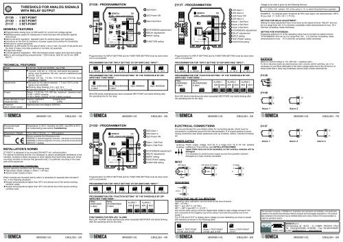
THRESHOLD FOR ANALOG SIGNALS<br />
WITH RELAY OUTPUT<br />
1 SET-POINT<br />
2 SET-POINT<br />
3 SET-POINT<br />
GENERAL FEATURES<br />
Programmable analog input via DIP-switch for current and voltage signals.<br />
Stabilized power supply for transducers 2 wires tecnique with protection against<br />
short-circuit.<br />
Alarms set-point regulation, regulation also for working delay and hysteresis.<br />
In<strong>di</strong>cations on the front for presence of power supply and overflow for thresholds.<br />
Test-point to control set-points.<br />
Selection by DIP-switch for the type of alarm ( min or max ) for each of set-points and<br />
the state of relays (normally powered or normally not powered).<br />
Output with relays.<br />
3 points galvanic separation, 1500 Vac between power supply and input and outputs.<br />
Box in auto extinguishing polycarbonate, 1 DIN module, back for rail 35 mm (DIN<br />
46277).<br />
TECHNICAL FEATURES<br />
Power:<br />
19-40 Vdc, 19-28 Vac 50-60Hz, max 2.5W.<br />
Input:<br />
Current 0-20 mA or 4-20 mA both active and passive<br />
wiring, input impedance 100 ohm, sensor's stabilized power<br />
20 Vdc 20 mA.<br />
Voltage 0-5 Vdc, 1-5 Vdc, 0-10 Vdc and 2-10 Vdc, input<br />
impedance 1 Mohm.<br />
Adjustments:<br />
Set-point for the alarms between 1 % and 100 % of the<br />
signal to be controlled.<br />
Working delay between 0,3 s and 30 s.<br />
Hysteresis between 2 % and 15 % for full-scale.<br />
Output:<br />
Relays, 1 A 30 Vdc / 5 A 250 Vac maximum (resistive load).<br />
Z113S 1 SPDT contacts,<br />
Z113D 2 SPST contacts, Z113T 3 SPST contacts.<br />
Errors referred to input Thermic coefficient: Linearity error:<br />
measure's field:<br />
0, 02%/°C 0,05%<br />
Protection<br />
Input / power supply:<br />
Against pulse overvoltages 400W/ms.<br />
Environemenytal<br />
con<strong>di</strong>tions:<br />
Dimensions / Weight:<br />
Norms:<br />
MI000901-I/E ENGLISH - 1/8<br />
MI000901-I/E<br />
ENGLISH - 3/8<br />
MI000901-I/E ENGLISH - 5/8 MI000901-I/E<br />
ENGLISH - 7/8<br />
Temperature: 0..50°C, Humi<strong>di</strong>ty min:30%, max 90% at 40°C<br />
not condensating (see section Installatione) .<br />
17,5 x 100 x 112 mm / 200 g approx.<br />
Device complies the following norms:<br />
EN50081-2 (electromagnetic emission, industrial environement)<br />
EN50082-2 (electromagnetic immunity, industrial environement)<br />
EN61010-1 (safety)<br />
INSTALLATION'S NORMS<br />
Z113S/D/T is designed to be mounted DIN 46277 rail, vertical position.<br />
For optimal functioning and life, it is necessary to assure anadequate ventilations to the<br />
modules, avoi<strong>di</strong>ng to place raceways or other objects that could close abat-vent. Avoid<br />
mounting modules on devices that generate heat; it is preferred mounting in the lower<br />
side of the square set.<br />
SEVERE OPERATING CONDITIONS:<br />
Severe operating con<strong>di</strong>tions are the following ones:<br />
High power supply voltage (> 30dcc / > 26 Vac).<br />
Sensor power supply at input.<br />
When modules are mounted side by side it is necessary to separate them at least 5<br />
mm. in the following situations:<br />
Square set temperature higher than 45°C and almost one of the severe working<br />
con<strong>di</strong>tion exists.<br />
Square set temperature higher than 35°C and almost two of the severe working<br />
con<strong>di</strong>tion exist.<br />
Z113S - PROGRAMMATION<br />
1 2 3<br />
4 5 6<br />
POWER<br />
3<br />
1<br />
ALARM<br />
SET<br />
+<br />
- 5<br />
S<br />
Z113S<br />
7 8 9<br />
10 11 12<br />
S SENECA<br />
Z113S SINGLE ALARM THRESHOLD<br />
POWER SUPPLY<br />
19 ÷ 28 V<br />
3<br />
INPUT<br />
19 ÷ 40 V=<br />
2<br />
1 2 3 4<br />
INPUT<br />
1 2 3 4<br />
0..20mA<br />
4..20mA<br />
volt or mA inputs mA inputs for 2 wire<br />
6<br />
0..5V<br />
1..5V<br />
5<br />
5<br />
0..10V<br />
4<br />
2..10V<br />
TEST-POINT OUTPUT<br />
FUNCTIONS<br />
7<br />
1 4<br />
8 1 2<br />
1 2<br />
Energised<br />
0-5V 5A 250Vac<br />
9<br />
relay in alarm<br />
De-energised<br />
relay in alarm<br />
DELAY<br />
Minimum<br />
0,3 s 30 s<br />
alarm<br />
KEY<br />
Maximum<br />
HYSTERESIS<br />
2%<br />
ON alarm<br />
15%<br />
WARNING! Disconnect power to unit prior to changing settings.<br />
ET001390B<br />
mA output<br />
8 9<br />
10<br />
12<br />
1 LED Alarm<br />
3 LED Power ON<br />
5 Alarm Set-Point<br />
8 HYSTERESIS adjustement<br />
9 DELAY adjustement<br />
10 INPUT setting<br />
12 FUNCTION setting<br />
Programmation for INPUT SETTING and for FUNCTION SETTING must be done when<br />
unit is not powered.<br />
PROGRAMMATION FOR “INPUT SETTING” BY DIP-SWITCHES “INPUT” :<br />
1 2 3 4 1 2 3 4 1 2 3 4 1 2 3 4 1 2 3 4 1 2 3 4<br />
0 - 20 mA 4 - 20 mA 0 - 5 V 1 - 5 V 0 - 10 V 2 - 10 V<br />
PROGRAMMATION FOR “FUNCTION SETTING” OF THE THRESHOLD BY DIP-<br />
SWITCHES “FUNCTIONS” :<br />
1 2 1 2 1 2 1 2<br />
Relay ENERGISED<br />
in alarm<br />
Relay DE-ENERGISED<br />
in alarm<br />
Alarm MINIMUM Alarm MAXIMUM<br />
Red LED starts instantaneously when exceeded SET-POINT and starts blinking after<br />
the operating time for the relay.<br />
Z113D - PROGRAMMATION<br />
1<br />
2<br />
1 2 3<br />
4 5 6<br />
A1 POWER<br />
A2 A3<br />
SET1<br />
SET2<br />
Z113D<br />
7 8 9<br />
10 11 12<br />
3<br />
5<br />
6<br />
S SENECA<br />
Z113D DOUBLE ALARM THRESHOLD<br />
INPUT<br />
1 2 3 4<br />
0..20mA<br />
4..20mA<br />
KEY<br />
1 2 3 4<br />
0..5V<br />
ON<br />
1..5V<br />
0..10V<br />
2..10V<br />
TEST-POINT<br />
FUNCTIONS<br />
1 2 3<br />
Normal<br />
1 2 3 4<br />
Energised<br />
function<br />
relay in alarm<br />
Setting<br />
De-energised<br />
Alarm 1<br />
Setting<br />
Alarm 2<br />
Setting<br />
Alarm 3<br />
1 2 3 4 1 2 3 4<br />
relay in alarm<br />
Minimum<br />
alarm 1<br />
Maximum<br />
alarm 1<br />
Minimum<br />
DELAY<br />
alarm 2<br />
Maximum<br />
0,3 s 30 s<br />
alarm 2<br />
Minimum<br />
HYSTERESIS<br />
alarm 3<br />
Maximum<br />
2% 15%<br />
alarm 3<br />
WARNING! Disconnect power to unit prior to changing settings.<br />
ET001410B<br />
8 9<br />
10<br />
11<br />
12<br />
1 LED Alarm 1<br />
2 LED Alarm 2<br />
3 LED Power ON<br />
5 Alarm 1 Set-Point<br />
6 Alarm 2 Set-Point<br />
8 HYSTERESIS adjustement<br />
9 DELAY adjustement<br />
10 INPUT setting<br />
11 TEST-POINT setting<br />
12 FUNCTION setting<br />
Programmation for INPUT SETTING and for FUNCTION SETTING must be done when<br />
unit is not powered.<br />
PROGRAMMATION FOR “INPUT SETTING” BY DIP-SWITCHES “INPUT” :<br />
1 2 3 4 1 2 3 4 1 2 3 4 1 2 3 4 1 2 3 4 1 2 3 4<br />
0 - 20 mA 4 - 20 mA 0 - 5 V 1 - 5 V 0 - 10 V 2 - 10 V<br />
PROGRAMMATION FOR “FUNCTION SETTING” OF THE THRESHOLD BY DIP-<br />
SWITCHES “FUNCTIONS” :<br />
Relay<br />
ENERGISED<br />
in alarm<br />
Relay<br />
DE-ENERGISED<br />
in alarm<br />
ALARM 1<br />
MIN MAX<br />
ALARM 2<br />
MIN MAX<br />
1 2 3 4 1 2 3 4 1 2 3 4 1 2 3 4 1 2 3 4 1 2 3 4<br />
FUNCTIONING FOR RED LED “ALARM<br />
Red LED “ALARM” starts istantaneusly when exceeded SET-POINT and starts blinking<br />
after the operating time for the relay .<br />
Z113T - PROGRAMMATION<br />
1<br />
2<br />
1 2 3<br />
4 5 6<br />
A1 POWER<br />
A2 A3<br />
SET1<br />
SET2<br />
SET3<br />
Z113T<br />
7 8 9<br />
10 11 12<br />
3<br />
4<br />
5<br />
6<br />
7<br />
Z113T TRIPLE ALARM THRESHOLD<br />
INPUT<br />
1 2 3 4<br />
0..20mA<br />
4..20mA<br />
KEY<br />
1 2 3 4<br />
0..5V<br />
ON<br />
1..5V<br />
0..10V<br />
2..10V<br />
TEST-POINT<br />
FUNCTIONS<br />
1 2 3<br />
Normal<br />
1 2 3 4<br />
Energised<br />
function<br />
relay in alarm<br />
Setting<br />
De-energised<br />
Alarm 1<br />
Setting<br />
Alarm 2<br />
Setting<br />
Alarm 3<br />
1 2 3 4 1 2 3 4<br />
relay in alarm<br />
Minimum<br />
alarm 1<br />
Maximum<br />
alarm 1<br />
Minimum<br />
DELAY<br />
alarm 2<br />
Maximum<br />
0,3 s 30 s<br />
alarm 2<br />
Minimum<br />
HYSTERESIS<br />
alarm 3<br />
Maximum<br />
2% 15%<br />
alarm 3<br />
WARNING! Disconnect power to unit prior to changing settings.<br />
1 LED Alarm 1<br />
2 LED Alarm 2<br />
3 LED Power ON<br />
4 LED Alarm 3<br />
5 Alarm 1 Set-Point<br />
6 Alarm 2 Set-Point<br />
7 Alarm 3 Set-Point<br />
8 HYSTERESIS adjustement<br />
9 DELAY adjustement<br />
10 INPUT setting<br />
11 TEST-POINT setting<br />
12 FUNCTION setting<br />
This document is property of SENECA srl. Duplication and reprodution are forbidden, if not authorized.<br />
Contents of the present documentation refers to products and technologies described in it. All technical<br />
data contained in the document may be mo<strong>di</strong>fied without prior notice Content of this documentation is<br />
subject to perio<strong>di</strong>cal revision.<br />
SENECA s.r.l.<br />
Via Germania, 34 - 35127 - Z.I. CAMIN - PADOVA - ITALY<br />
Tel. +39.049.8705355 - 8705359 - Fax +39.049.8706287<br />
e-mail: info@seneca.it - www.seneca.it<br />
MI000901-I/E ENGLISH - 2/8 MI000901-I/E<br />
ENGLISH - 4/8<br />
MI000901-I/E ENGLISH - 6/8 MI000901-I/E<br />
ENGLISH - 8/8<br />
S SENECA<br />
ET001410B<br />
8 9<br />
Programmation for INPUT SETTING and for FUNCTION SETTING must be done when<br />
unit is not powered.<br />
PROGRAMMATION FOR “INPUT SETTING” BY DIP-SWITCHES “INPUT” :<br />
1 2 3 4 1 2 3 4 1 2 3 4 1 2 3 4 1 2 3 4 1 2 3 4<br />
0 - 20 mA 4 - 20 mA 0 - 5 V 1 - 5 V 0 - 10 V 2 - 10 V<br />
PROGRAMMATION FOR “FUNCTION SETTING” OF THE THRESHOLD BY DIP-<br />
SWITCHES “FUNCTIONS” :<br />
Relay<br />
ENERGISED<br />
in alarm<br />
Relay<br />
DE-ENERGISED<br />
in alarm<br />
ALARM 1<br />
MIN MAX<br />
ALARM 2<br />
MIN MAX<br />
ALARM 3<br />
MIN MAX<br />
1 2 3 4 1 2 3 4 1 2 3 4 1 2 3 4 1 2 3 4 1 2 3 4 1 2 3 4 1 2 3 4<br />
Red LED starts instantaneously when exceeded SET-POINT and starts blinking after<br />
the operating time for the relay.<br />
ELECTRICAL CONNECTIONS<br />
It is reccommanded the use shilded cables for connecting signals; shield must be<br />
connected to a preferred ground for the instrumentation. It is a good practice to avoid<br />
routing conductors near power appliances sush as inverters, motors, induction furnaces<br />
etc.<br />
POWER SUPPLY<br />
19-40Vdc Power supply voltage must be in a range from 19 to 40 Vdc (polarity<br />
19-28Vac in<strong>di</strong>fferent), 19 and 28 Vac; see INSTALLATION<br />
NORMS.<br />
Upper limits have not to be exceeded, on the contrary modules will be<br />
damaged.<br />
2 3 It is necessary to protect power supply source from possible module's<br />
damages by a fuse correctly calculated.<br />
INPUT<br />
mA Input<br />
-<br />
mA<br />
+<br />
+ -<br />
Vext<br />
TEST-POINT<br />
+<br />
0-5 V<br />
-<br />
1<br />
4<br />
5<br />
4<br />
mA Input (2 wires)<br />
+<br />
6<br />
mA<br />
-<br />
5<br />
OPERATING VALUE CALIBRATION<br />
Operating value calibration must be done by the front trimmers :<br />
SET ( Z113S )<br />
SET 1 and SET 2 ( Z113D )<br />
SET 1, SET 2 and SET 3 ( Z113T )<br />
and can be verify using a common <strong>di</strong>gital tester setted to read voltage at least 5 Vdc<br />
and connected to the negative cap to the clamp 4 and with the positive one to the<br />
clamp 1.<br />
For Z113D and Z113T to <strong>di</strong>splay alarm voltage you are calibrating you have to preset<br />
DIP-switches as shown in the following table.<br />
1 2 3 1 2 3 1 2 3<br />
Alarm 1 TEST-POINT<br />
Z113D and Z113T<br />
Alarm 2 TEST-POINT<br />
Z113D and Z113T<br />
10<br />
11<br />
12<br />
V Input<br />
+<br />
V<br />
-<br />
5<br />
4<br />
Alarm 3 TEST-POINT<br />
Z113T<br />
Voltage to be read is given by the following formula :<br />
V = 0,05 x VS (where VS is the value in % to which threshold have operate)<br />
EXAMPLE : To calibrate alarm threshold atl 35% input signal, set potentiometer «SET»<br />
till you read V = 0,05 x 35 = 1,75 Vdc.<br />
SETTING FOR DELAY ADJUSTMENT :<br />
Setting for delay adjustment have to be done by the lateral trimmer “DELAY” and can<br />
be in a range from min. 0,3 s (trimmer completely rotate anticlockwise) to max. 30 s<br />
(trimmer completely rotate clockwise).<br />
SETTING FOR HYSTERESIS :<br />
Hysteresis setting (in % of the operating value) has to be done by lateral trimmer<br />
“HYSTERESIS” and can be in a range from min. 2 % (trimmer completely rotate<br />
anticlockwise) to max. 15 % (trimmer completely rotate clockwise)<br />
OUTPUTS<br />
Maximun load for relays is 5 A 250 Vac ( resistive load )..<br />
To drive inductive loads (as electrovalves coils, remote control switches, etc.) it is<br />
necessary to use filters de<strong>di</strong>cated to the extra voltage spike due to the off and on of<br />
those loads that in other way drastically reduce relay contact electrical life.<br />
Z113S<br />
Z113D<br />
7<br />
8<br />
9<br />
Alarm 1 Alarm 2<br />
Z113T<br />
9 10<br />
8 7<br />
9 10 12<br />
8 7 11<br />
Alarm 1 Alarm 2 Alarm 3<br />
R<br />
THE INTERNATIONAL CERTIFICATION NETWORK<br />
ISO9001-2000