System Connections (CPS Plus * Stand – Alone *) - GPS Standard
System Connections (CPS Plus * Stand – Alone *) - GPS Standard
System Connections (CPS Plus * Stand – Alone *) - GPS Standard

Create successful ePaper yourself
Turn your PDF publications into a flip-book with our unique Google optimized e-Paper software.
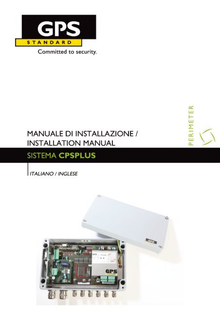
Manuale di Installazione Sistema <strong>CPS</strong>PLUS<br />
Versione documento: T-<strong>CPS</strong>PLUS/115/09<br />
Versione FW: - -<br />
Versione HW: - -<br />
Versione SW: - -<br />
Lingua: Italiano / Inglese<br />
"Copyright by <strong>GPS</strong> <strong>Stand</strong>ard SpA.<br />
I diritti di traduzione, di riproduzione e di adattamento totale o parziale e con qualsiasi<br />
mezzo sono riservati per tutti i paesi.<br />
<strong>GPS</strong> <strong>Stand</strong>ard si riserva di apportare modifiche alle caratteristiche tecniche senza<br />
preavviso. Le informazioni fornite in questo documento possono essere soggette a<br />
modifiche e/o errori. Per informazioni dettagliate contattate il vostro riferimento <strong>GPS</strong><br />
<strong>Stand</strong>ard."<br />
1
2<br />
Manuale di Installazione Sistema <strong>CPS</strong>PLUS<br />
Indice - Index<br />
Indice - Index .......................................................................................................................2<br />
DESCRIZIONE GENERALE................................................................................................5<br />
DESCRIZIONI di SISTEMA .................................................................................................5<br />
Applicazioni ..................................................................................................................5<br />
Principio di funzionamento............................................................................................5<br />
COMPONENTI di SISTEMA ................................................................................................6<br />
Cavo Microfonico..........................................................................................................6<br />
Sensore <strong>CPS</strong> <strong>Plus</strong>........................................................................................................6<br />
CONFIGURAZIONI di SISTEMA .........................................................................................7<br />
Versione <strong>CPS</strong> <strong>Plus</strong> “<strong>Stand</strong>-<strong>Alone</strong>” (Art. P<strong>CPS</strong>2001/SA)..............................................7<br />
Versione <strong>CPS</strong> <strong>Plus</strong> “Multiplex” (Art. P<strong>CPS</strong>2001) .........................................................7<br />
CAVO MICROFONICO........................................................................................................8<br />
Generalità ............................................................................................................................8<br />
Installazione su rete metallica.......................................................................................8<br />
Installazione su muro..................................................................................................12<br />
KIT di TERMINAZIONE ZONA ..........................................................................................13<br />
KIT di GIUNZIONE ZONA..................................................................................................13<br />
PROCEDURE D’ INSTALLAZIONE...................................................................................14<br />
NOZIONI PRELIMINARI ....................................................................................................14<br />
Individuazione del perimetro.......................................................................................14<br />
Zone di rilevazione......................................................................................................14<br />
Applicazione su rete metallica ....................................................................................14<br />
Applicazione su muro .................................................................................................14<br />
Accorgimenti in presenza di vegetazione ...................................................................14<br />
INSTALLAZIONE SENSORE <strong>CPS</strong> <strong>Plus</strong> ............................................................................15<br />
Nelle immediate vicinanze della protezione................................................................15<br />
A distanza dalla protezione.........................................................................................15<br />
CABINET <strong>CPS</strong> <strong>Plus</strong>...........................................................................................................16<br />
DESCRIZIONE GENERALE..............................................................................................16<br />
Vista esterna <strong>CPS</strong> <strong>Plus</strong> Multiplex ...............................................................................16<br />
Vista esterna <strong>CPS</strong> <strong>Plus</strong> <strong>Stand</strong>-<strong>Alone</strong>..........................................................................16<br />
Fissaggio Cabinet.......................................................................................................17<br />
Protezione Cabinet (Anti-apertura) .............................................................................17<br />
<strong>CPS</strong> <strong>Plus</strong> <strong>Stand</strong> - <strong>Alone</strong> (Art. P<strong>CPS</strong>2001/SA) ...................................................................18<br />
Collegamenti di Sistema (<strong>CPS</strong> <strong>Plus</strong> * <strong>Stand</strong> <strong>–</strong> <strong>Alone</strong> * ) (versione con COM115) ............21<br />
Collegamenti di Sistema (<strong>CPS</strong> <strong>Plus</strong> * <strong>Stand</strong> <strong>–</strong> <strong>Alone</strong> * ) (versione con USB) ...................22<br />
<strong>CPS</strong> <strong>Plus</strong> Multiplex (Art. P<strong>CPS</strong>2001).................................................................................24<br />
TERMINAZIONE LINEA di COMUNICAZIONE “COM115”................................................26<br />
Linea Seriale <strong>GPS</strong> “Communication 115” (COM115) ........................................................27<br />
Dip-Switch Selezione Indirizzo Sensore ............................................................................28<br />
Collegamenti di Sistema (<strong>CPS</strong> <strong>Plus</strong> * Multiplex*)..............................................................29<br />
Collegamento RS232.........................................................................................................30<br />
CONSIDERAZIONI FINALI................................................................................................31<br />
Riepilogo delle principali operazioni di installazione ..........................................................31<br />
Parametri e Taratura del Sistema <strong>CPS</strong> <strong>Plus</strong>......................................................................33<br />
Procedura di Taratura Sistema <strong>CPS</strong> <strong>Plus</strong>..........................................................................34<br />
CARATTERISTICHE di SISTEMA.....................................................................................47<br />
GENERAL DESCRIPTION ................................................................................................50
Manuale di Installazione Sistema <strong>CPS</strong>PLUS<br />
SYSTEM DESCRIPTION...................................................................................................50<br />
Applications ................................................................................................................50<br />
Operating Principles ...................................................................................................50<br />
SYSTEM COMPONENTS .................................................................................................51<br />
Microphonic Cable......................................................................................................51<br />
<strong>CPS</strong> <strong>Plus</strong> Sensor........................................................................................................51<br />
SYSTEM CONFIGURATIONS...........................................................................................52<br />
<strong>CPS</strong> <strong>Plus</strong> “<strong>Stand</strong>-<strong>Alone</strong>” Version (P<strong>CPS</strong>2001/SA).............................................................52<br />
<strong>CPS</strong> <strong>Plus</strong> “Multiplex” Version (P<strong>CPS</strong>2001).......................................................................52<br />
MICROPHONIC CABLE ....................................................................................................53<br />
General..............................................................................................................................53<br />
Installation on a metallic fence...........................................................................................53<br />
Installation on a wall...........................................................................................................56<br />
ZONE TERMINATION KIT P<strong>CPS</strong>320/N ............................................................................57<br />
JOINT KIT P<strong>CPS</strong>321/2 ......................................................................................................57<br />
INSTALLATION PROCEDURE .........................................................................................58<br />
PRELIMINARY CONSIDERATIONS .................................................................................58<br />
Identifying the Perimeter.............................................................................................58<br />
Zone Allocation...........................................................................................................58<br />
Metal Fence Applications............................................................................................58<br />
Wall Applications ........................................................................................................58<br />
Actions in the presence of vegetation.........................................................................58<br />
INSTALLATION OF <strong>CPS</strong> <strong>Plus</strong> SENSOR...........................................................................59<br />
Adjacent to the protected structure ....................................................................................59<br />
Remote from the protected structure .................................................................................59<br />
<strong>CPS</strong> <strong>Plus</strong> CABINET ...........................................................................................................60<br />
GENERAL DESCRIPTION ................................................................................................60<br />
External view <strong>CPS</strong> <strong>Plus</strong> Multiplex...............................................................................60<br />
External view <strong>CPS</strong> <strong>Plus</strong> <strong>Stand</strong>-<strong>Alone</strong> .........................................................................60<br />
Fixing the Cabinet.......................................................................................................61<br />
Cabinet Protection (Anti-tamper) ................................................................................61<br />
<strong>CPS</strong> <strong>Plus</strong> <strong>Stand</strong> - <strong>Alone</strong> (P<strong>CPS</strong>2001/SA) ..........................................................................62<br />
<strong>System</strong> <strong>Connections</strong> (<strong>CPS</strong> <strong>Plus</strong> * <strong>Stand</strong> <strong>–</strong> <strong>Alone</strong> *) (Version COM115) ...........................65<br />
<strong>CPS</strong> <strong>Plus</strong> Multiplex (P<strong>CPS</strong>2001) .......................................................................................67<br />
COMMUNICATION “COM115” LINE TERMINATION........................................................68<br />
<strong>GPS</strong> “Communication 115” (COM115) Serial Line ............................................................69<br />
Dip-Switch Selection Sensor Address................................................................................70<br />
<strong>System</strong> <strong>Connections</strong> (<strong>CPS</strong> <strong>Plus</strong> * Multiplex*) ...................................................................71<br />
RS232 <strong>Connections</strong>...........................................................................................................72<br />
FINAL CONSIDERATIONS ...............................................................................................73<br />
Setting Up the <strong>CPS</strong> <strong>Plus</strong> <strong>System</strong> Parameters ...................................................................75<br />
Setup of <strong>CPS</strong> <strong>Plus</strong> system.................................................................................................76<br />
SYSTEM CHARACTERISTICS .........................................................................................88<br />
3
4<br />
Manuale di Installazione Sistema <strong>CPS</strong>PLUS<br />
Manuale di Installazione<br />
<strong>CPS</strong>PLUS<br />
VERSIONE ITALIANO
DESCRIZIONI di SISTEMA<br />
Applicazioni<br />
Manuale di Installazione Sistema <strong>CPS</strong>PLUS<br />
DESCRIZIONE GENERALE<br />
Il <strong>CPS</strong> <strong>Plus</strong> è un sistema di anti-intrusione perimetrale passivo, adatto sia per<br />
applicazioni esterne che per applicazioni interne. Viene normalmente installato su<br />
recinzioni esterne pre-esistenti come reti a maglie sciolte, ma può essere utilizzato anche<br />
in superficie o all’interno di strutture in muratura (soffitti, pareti, muri di cinta, .... ecc.).<br />
Rete<br />
Cavo Microfonico<br />
Progettato per rilevare tutte quelle manovre d’intrusione tipiche di uno scavalcamento della<br />
recinzione, di un taglio della rete o di un suo sollevamento, oppure, nel caso di<br />
applicazione interne, per segnalare possibili tentativi di sfondamento o penetrazione del<br />
muro, risulta adatto sia come protezione primaria nel caso di impianti a rischio medio <strong>–</strong><br />
alto, sia come protezione secondaria (abbinata per esempio a sistemi di<br />
Televideosorveglianza) nel caso di impianti ad altissimo rischio.<br />
Principio di funzionamento<br />
Cavo Microfonico<br />
Muro di cinta<br />
Il funzionamento del <strong>CPS</strong> <strong>Plus</strong>, si basa sul rilevamento da parte del Cavo Microfonico di<br />
tutte quelle sollecitazioni meccaniche tipicamente sviluppate nel corso di un tentativo<br />
d’intrusione. Queste sollecitazioni producono delle deformazioni del Cavo Microfonico<br />
stesso, il quale, per un effetto elettromagnetico (“triboelettrico”), le traduce in segnali<br />
elettrici.<br />
Il sensore analizza quindi, istante per istante, il segnale elettrico presente sul Cavo<br />
Microfonico e, qualora questo superi una soglia prestabilita, esegue un’accurata analisi<br />
matematica del segnale stesso nel dominio delle frequenze.<br />
La comparazione della maschera di energia ottenuta con quelle memorizzate, genera una<br />
eventuale segnalazione di allarme.<br />
5
Cavo Microfonico<br />
6<br />
Manuale di Installazione Sistema <strong>CPS</strong>PLUS<br />
COMPONENTI di SISTEMA<br />
Il Cavo Microfonico viene installato lungo l’intero perimetro dell’area protetta.<br />
Le sue peculiari caratteristiche lo rendono particolarmente sensibile alle sollecitazioni<br />
meccaniche prodotte nel corso di un tentativo di violazione della protezione (sfondamento,<br />
scavalcamento, taglio, ... ecc.); queste sollecitazioni vengono tradotte in un segnale<br />
elettrico (effetto “triboelettrico”) continuamente analizzato dal Sensore <strong>CPS</strong> <strong>Plus</strong>.<br />
A seconda della conformazione del perimetro e del grado di sensibilità che si vuole<br />
ottenere, la distribuzione del Cavo potrà assumere diverse configurazioni, ma in ogni caso<br />
non potranno essere utilizzati più di 300 m di Cavo per zona.<br />
Sensore <strong>CPS</strong> <strong>Plus</strong><br />
Esistono due versioni del Sensore <strong>CPS</strong> <strong>Plus</strong>: <strong>Stand</strong>-<strong>Alone</strong> (Art. P<strong>CPS</strong>2001/SA) con uscite<br />
su contatti di relè NC, e seriale (Art. P<strong>CPS</strong>2001) collegabile al Sistema Multiplex 2000,<br />
dove le segnalazioni transitano via cavo verso la UCP (Unità di Controllo Perimetrale), che<br />
può gestire sino a 64 Sensori contemporaneamente ed a cui sono collegate le Schede<br />
Relè di ogni Sensore remoto.<br />
Progettato utilizzando la tecnologia DSP (Digital Signal Processing), che mette a<br />
disposizione un’enorme potenza di calcolo e permette quindi l’implementazione di<br />
trasformate di Fourier, Filtri Digitali ed altro ancora, è in grado di gestire in modo separato<br />
due distinte zone (CANALI) da 300 m ciascuna, fornendo per ognuna le segnalazioni di<br />
Pre-allarme, d’Allarme, Taglio o cortocircuito del Cavo, disponibili tramite contatti NC sulla<br />
versione <strong>Stand</strong>-<strong>Alone</strong> (Art. P<strong>CPS</strong>2001/SA), o via seriale COM115 per la versione<br />
Multiplex (Art. P<strong>CPS</strong>2001).<br />
Grazie a queste possibilità fornitaci dal DSP, si possono eliminare disturbi ambientali in<br />
modo più semplice e, ridurre la generazione di falsi allarmi. Tramite la linea seriale<br />
COM115 è possibile parametrizzare, monitorare e registrare i segnali direttamente con un<br />
Personal Computer ed il Software dedicato (Art. PUCP2000SW).<br />
E’contenuto in apposito Cabinet metallico completamente stagno e autoprotetto.
Manuale di Installazione Sistema <strong>CPS</strong>PLUS<br />
CONFIGURAZIONI di SISTEMA<br />
Versione <strong>CPS</strong> <strong>Plus</strong> “<strong>Stand</strong>-<strong>Alone</strong>” (Art. P<strong>CPS</strong>2001/SA)<br />
Recinzione<br />
ZONA1(CANALE1)<br />
P.C. di Configurazione<br />
COM_A<br />
COM_B<br />
COM_A<br />
COM_ B<br />
GND<br />
+12V<br />
_<br />
_<br />
RL1<br />
RL8<br />
TAMPER<br />
RL2 _<br />
RL3 IN1<br />
I N2<br />
RL 4<br />
I N3<br />
I N4<br />
I N5<br />
RL5<br />
I N6<br />
I N7<br />
RL6<br />
I N8<br />
RL7 _<br />
1 2 3 4 5 6 7 8<br />
ON<br />
US CIT A<br />
CUFF I A<br />
AUDIO IN/O UT<br />
CHA<br />
_<br />
_<br />
CHB<br />
AM P _ OUT<br />
_<br />
_<br />
A NA 2<br />
_<br />
_<br />
Sensore<strong>CPS</strong><strong>Plus</strong><br />
e<br />
CavoMicrofonico<br />
ANA1<br />
Centraled' Allarme<br />
ZONA2(CANALE2)<br />
Fornisce di serie, in morsettiera, i contatti NC di Pre-Allarme, Allarme, Taglio e Corto per il<br />
canale “1” e per il canale “2”, oltre alle segnalazioni di Guasto e Tamper, la linea seriale<br />
COM115 e Ingressi NC/NO locali.<br />
Versione <strong>CPS</strong> <strong>Plus</strong> “Multiplex” (Art. P<strong>CPS</strong>2001)<br />
Recinzione<br />
DALLAUCP COM115 COM115 VERSOPROSSIMOSENSORE<br />
ZONA1 (CANALE1)<br />
COM_A<br />
COM_B<br />
COM_A<br />
COM_ B<br />
GND<br />
+12V<br />
_<br />
_<br />
RL1<br />
RL8<br />
TAMP ER<br />
RL2 _<br />
IN1<br />
RL3<br />
I N2<br />
RL 4<br />
I N3<br />
I N4<br />
I N5<br />
RL5 I N6<br />
I N7<br />
RL6<br />
I N8<br />
RL7 _<br />
1 2 3 4 5 6 7 8<br />
ON<br />
US CIT A<br />
CUFF I A<br />
AUDIO IN/OUT<br />
CHA<br />
_<br />
_<br />
CHB<br />
A MP _ OUT<br />
_<br />
_<br />
A NA 2<br />
_<br />
_<br />
Sensore <strong>CPS</strong><strong>Plus</strong><br />
e<br />
CavoMicrofonico<br />
ANA1<br />
ZONA2(CANALE2)<br />
Fornisce, via seriale COM115, le segnalazioni di Pre-Allarme, Allarme, Taglio e Corto per<br />
il canale “1” e “2”, oltre alle segnalazioni di Guasto e Tamper.<br />
Uscite Relè e Ingressi NC/NO locali sono opzionali.<br />
7
Generalità<br />
8<br />
Manuale di Installazione Sistema <strong>CPS</strong>PLUS<br />
CAVO MICROFONICO<br />
La peculiarità del Cavo sensibile utilizzato nel Sistema <strong>CPS</strong> è quella di possedere delle<br />
caratteristiche microfoniche che lo rendono capace di rilevare tutte quelle sollecitazioni<br />
meccaniche tipicamente esercitate nel corso di un’intrusione (sfondamento di un muro;<br />
scavalcamento e taglio di una rete; ... ecc.). Trattasi di un cavo coassiale schermato dal<br />
diametro esterno di 2,5 mm, in grado di tradurre le sollecitazioni di cui sopra in un segnale<br />
elettrico (effetto “triboelettrico”) continuamente analizzato dall’Unità di Controllo.<br />
Installazione su rete metallica<br />
L’installazione del Cavo sensibile inizia generalmente dalla giunzione (eventuale) con<br />
l’RG59 proveniente dal Sensore <strong>CPS</strong> <strong>Plus</strong>.<br />
Qui di seguito vengono descritte le principali operazioni da compiersi nel corso<br />
dell’applicazione del Cavo Microfonico su reti metalliche.<br />
1) svolgere la matassa di Cavo sensibile (Art. P<strong>CPS</strong>313) lungo l’intera protezione, avendo<br />
cura di fissarlo provvisoriamente in corrispondenza dei pali a sostegno della rete.<br />
(In questo modo il Cavo verrà mantenuto sollevato da terra e si eviteranno così<br />
possibili danneggiamenti). Ricordarsi di lasciare una ricchezza di Cavo utile per<br />
effettuare l’eventuale giunzione con l’RG59.<br />
2) prevedere un poco di gioco in corrispondenza di ogni palo di supporto, in modo da<br />
poterlo scavalcare; sarebbe comunque bene creare un “Loop” (20 ÷ 30 cm di cavo)<br />
ogni 15 m circa, sempre in corrispondenza dei pali di supporto, anche per facilitare gli<br />
eventuali interventi di riparazione (in caso di danneggiamento o di taglio cavo).<br />
Ancorare il cavo sensibile (sulla rete) lateralmente ai pali e non a contatto diretto degli<br />
stessi.<br />
N. B.: sarà cura dell’installatore il prevedere la migliore disposizione del cavo sensibile<br />
sulla rete, tenendo conto delle caratteristiche della recinzione (struttura fisica,<br />
lunghezza, altezza, ecc.) e del grado di sensibilità necessario alla protezione.
In ogni caso è bene ricordare che:<br />
Manuale di Installazione Sistema <strong>CPS</strong>PLUS<br />
Il cavo sensibile deve essere applicato sulla recinzione in modo tale che la sua<br />
sensibilità sia distribuita omogeneamente su tutta l’altezza della rete, evitando quindi di<br />
passare con il cavo stesso in prossimità dei tenditori orizzontali della rete, di generare<br />
attorcigliamenti o nette variazioni del suo percorso, e di compiere tutte quelle<br />
operazioni improprie che potrebbero compromettere un’efficiente funzionalità del<br />
sistema.<br />
In base all’altezza della recinzione sarà opportuno prevedere un doppio passaggio<br />
(andata / ritorno) del cavo microfonico, tenendo però sempre presente la lunghezza<br />
massima che il cavo microfonico può coprire (300 m circa per zona).<br />
3) Una volta terminata la disposizione provvisoria, fissare il Cavo sensibile alla rete in<br />
modo definitivo tramite le apposite fascette (Art. P<strong>CPS</strong>110), prevedendone una ogni<br />
20 ÷ 30 cm Evitare di assicurare il Cavo in corrispondenza dei nodi generati<br />
dall’intersezione delle maglie. Verificare la tensione del Cavo lungo il suo intero<br />
percorso; questi dovrà essere sufficientemente tirato per evitare inopportuni<br />
movimenti (per esempio in caso di forte vento), ma non dovrà mai essere sottoposto<br />
ad eccessiva tensione.<br />
Nelle pagine successive vengono riportate le raffigurazioni relative alle informazioni di cui<br />
sopra e ad alcune tipiche situazioni quali:<br />
l’interruzione della recinzione;<br />
la presenza di cancelli (a doppio battente);<br />
il passaggio del Cavo sensibile in prossimità di angoli;<br />
l’intersezione di due Zone.<br />
Portare a termine gli ultimi collegamenti del cavo con il sensore e quindi procedere<br />
all’installazione dell’unità d’analisi.<br />
Dopo aver portato a termine i collegamenti ed installato tutti i sensori, il sistema è pronto<br />
per la messa in funzione e il collaudo.<br />
9
10<br />
1/3<br />
1/3<br />
1/3<br />
Recinzione<br />
Recinzione<br />
Manuale di Installazione Sistema <strong>CPS</strong>PLUS<br />
Scavalcamento Palo di supporto<br />
SI !<br />
Ricchezza di Cavo<br />
per eventuale giunzione<br />
con RG59<br />
NO !<br />
SI !<br />
Fascetta per ancoraggio Cavo<br />
(una ogni circa 20 - 30 cm.)<br />
NO !
Recinzione<br />
Loop<br />
Kit di<br />
Giunzione<br />
(Art. P<strong>CPS</strong>322)<br />
Canalina<br />
PVC<br />
Cavo<br />
RG59<br />
Cavo Microfonico<br />
Recinzione<br />
Palo di supporto rete<br />
Canalina<br />
PVC<br />
Manuale di Installazione Sistema <strong>CPS</strong>PLUS<br />
Interruzione recinzione<br />
Kit di Giunzione<br />
(Art. P<strong>CPS</strong>322)<br />
Cavo<br />
RG59<br />
Interramento 40 - 50 cm. circa<br />
Cavo Microfonico<br />
Cancello a doppio battente<br />
Interramento 40 - 50 cm. circa<br />
Loop di 20 - 30 cm.<br />
(ogni 15 mt. circa)<br />
11
12<br />
Recinzione<br />
Installazione su muro<br />
ZONA 1<br />
Manuale di Installazione Sistema <strong>CPS</strong>PLUS<br />
Intersezione di due Zone<br />
ZONA 2<br />
Kit di Terminazione Zona (Art. <strong>CPS</strong>320)<br />
Per l’installazione del cavo sensibile su strutture in muratura (soffitti, pareti, muretti di<br />
cinta, ecc.) valgono essenzialmente le principali considerazioni fatte per l’applicazione del<br />
cavo microfonico su reti metalliche.<br />
In particolare, si consiglia di infilare il cavo microfonico in una canalina in PVC (quella<br />
normalmente utilizzata negli impianti elettrici) in modo da prevenirne possibili<br />
danneggiamenti. La stessa canalina potrà poi essere fissata o sulla superficie esterna<br />
della struttura, oppure laddove esistano (o vengano previste) opportune predisposizioni,<br />
all’interno del muro stesso.
Manuale di Installazione Sistema <strong>CPS</strong>PLUS<br />
KIT di TERMINAZIONE ZONA<br />
art. P<strong>CPS</strong>320/N<br />
Al fine di un corretto funzionamento dell’intero Sistema, ciascuna Zona (max 300 m di<br />
cavo sensibile, nel computo dei quali devono essere considerati anche gli eventuali metri<br />
di cavo non sensibile RG59 eventualmente utilizzati) deve necessariamente essere<br />
terminata con l’apposito Kit P<strong>CPS</strong>320/N.<br />
R<br />
F<br />
L<br />
Calza<br />
Collegare il cavo microfonico come nella figura sopra riportata.<br />
Cavo Microfonico<br />
P<strong>CPS</strong>312<br />
P<strong>CPS</strong>313<br />
Inserire quindi il sacchettino di Sali essiccanti all’interno del Kit per far sì che l’umidità<br />
residua non si depositi sui contatti e sulle viti del connettore.<br />
Dopo aver chiuso il TAPPO ed il PG FERMACAVO, utilizzare lo spezzone di guaina<br />
termorestringente (auto <strong>–</strong> incollante) per sigillare l’intero Kit di Terminazione.<br />
KIT di GIUNZIONE ZONA<br />
art. P<strong>CPS</strong>321/2<br />
Nel corso dell’installazione del Cavo Sensibile (o nelle successive eventuali opere di<br />
manutenzione) sarà talvolta necessario eseguire delle giunzioni tipo:<br />
CAVO MICROFONICO / CAVO RG59<br />
CAVO MICROFONICO / CAVO MICROFONICO<br />
Il primo caso può presentarsi quando il sensore <strong>CPS</strong> <strong>Plus</strong> viene installato a distanza dalla<br />
recinzione dove è installato il cavo sensibile, oppure laddove sia necessario lo<br />
scavalcamento di un passo carraio, di un cancello, ecc.<br />
Il secondo caso può presentarsi in seguito al danneggiamento di un tratto di cavo sensibile<br />
già installato.<br />
Cavo Microfonico<br />
P<strong>CPS</strong>312<br />
P<strong>CPS</strong>313 oppure<br />
RG59<br />
Collegare i cavi come nella figura sopra riportata.<br />
Calza<br />
Cavo Microfonico<br />
P<strong>CPS</strong>312<br />
P<strong>CPS</strong>313 oppure<br />
RG59<br />
Inserire quindi il sacchettino di sali essiccanti all’interno del Kit per far sì che l’umidità<br />
residua non si depositi sui contatti e sulle viti del connettore.<br />
Mantenendo i PG FERMACAVO aperti, serrare il Kit di Giunzione.<br />
Chiudere i PG FERMACAVO ed utilizzare lo spezzone di guaina termorestringente (auto <strong>–</strong><br />
incollante) per sigillare l’intero Kit di Terminazione.<br />
13
NOZIONI PRELIMINARI<br />
Individuazione del perimetro<br />
14<br />
Manuale di Installazione Sistema <strong>CPS</strong>PLUS<br />
PROCEDURE D’ INSTALLAZIONE<br />
Prima di procedere all’installazione dell’impianto è importante individuare la conformazione<br />
e la lunghezza dell’intero perimetro di sicurezza, in modo da poterne effettuare una<br />
corretta suddivisione in zone.<br />
Zone di rilevazione<br />
È opportuno che ciascuna zona di rilevazione sia costituita dallo stesso tipo di recinzione<br />
(rete a maglie sciolte, o struttura in muratura) e sia il più possibile omogenea (stesso<br />
materiale, stesso grado di messa in tensione, stessa altezza, ecc.). Ciascuna delle zone in<br />
cui viene suddiviso il perimetro non deve superare i 300 m<br />
Applicazione su rete metallica<br />
Possono essere utilizzate le più comuni specie di rete, ma molto importante sarà il<br />
valutarne la condizione lungo l’intera protezione (lo stato, la messa in tensione, il fissaggio<br />
ai pali di supporto, ... ecc.).<br />
Il Cavo Microfonico viene fissato alla rete tramite delle fascette; sarà cura dell’installatore<br />
definire il suo percorso in base al grado di sensibilità necessario alla protezione.<br />
In questo caso il Sistema <strong>CPS</strong> <strong>Plus</strong> è in grado di rilevare tutte quelle azioni atte a tagliare,<br />
sfondare, o scavalcare la rete.<br />
Applicazione su muro<br />
Nel caso di applicazioni in interni (muri in mattoni, strutture in cemento, ... ecc.) è<br />
raccomandabile far passare il Cavo sensibile all’interno di canaline in PVC (... quelle<br />
normalmente utilizzate negli impianti elettrici). Questa soluzione offre un più efficace<br />
mezzo per mantenere il contatto con la superficie protetta e per ridurre l’usura del cavo<br />
stesso.<br />
In questo secondo tipo di applicazione il Sistema <strong>CPS</strong> <strong>Plus</strong> è in grado di rilevare fenomeni<br />
di deflagrazione (esplosioni), o comunque attacchi diretti alla protezione per mezzo di<br />
martelli pneumatici e altri strumenti meccanici.<br />
Accorgimenti in presenza di vegetazione<br />
Al fine di evitare possibili false rilevazioni da parte del Cavo Microfonico, sarebbe<br />
opportuno rimuovere tutte quelle forme di vegetazione che potrebbero entrare in contatto<br />
(direttamente o indirettamente) con la protezione ed interagire con essa.
Manuale di Installazione Sistema <strong>CPS</strong>PLUS<br />
INSTALLAZIONE SENSORE <strong>CPS</strong> <strong>Plus</strong><br />
Nelle immediate vicinanze della protezione<br />
Questa prima condizione è quella ritenuta migliore in quanto l’installazione del Sensore<br />
<strong>CPS</strong> <strong>Plus</strong> nelle immediate vicinanze della protezione oltre a permettere il collegamento<br />
diretto con il Cavo Microfonico e quindi diminuire possibili disturbi, facilita anche tutte<br />
quelle operazioni necessarie alla taratura dell’impianto e agli interventi di manutenzione.<br />
È comunque consigliabile fissare il Sensore su di una struttura di supporto (generalmente<br />
un muro o una parete, ma può andar bene anche un pozzetto di contenimento) diversa da<br />
quella protetta con il Cavo Sensibile; dove questa struttura non dovesse esistere, sarebbe<br />
comunque preferibile costruirla.<br />
Recinzione Struttura di supporto<br />
A distanza dalla protezione<br />
Quando il Sensore <strong>CPS</strong> <strong>Plus</strong> viene posizionato a distanza dalla protezione, per effettuare<br />
il collegamento tra il Cavo Microfonico e lo stesso Sensore, è necessario utilizzare del<br />
cavo coassiale non sensibile (RG59) e l’apposito Kit di Giunzione.<br />
È consigliabile inoltre, coprire l’intero percorso del suddetto cavo con una Canalina in<br />
PVC (quella utilizzata comunemente negli impianti elettrici); la stessa dovrà essere<br />
interrata ad una profondità di circa 40 ÷ 50 cm e resa completamente stagna al fine di<br />
evitare possibili infiltrazioni. Si ricorda che nei 300 m (max) di Cavo Microfonico che<br />
possono essere utilizzati a copertura di una singola zona, devono essere considerati<br />
anche i metri di cavo RG59 utilizzati.<br />
Recinzione<br />
Kit di Giunzione<br />
(Art. P<strong>CPS</strong>322)<br />
Canalina<br />
PVC<br />
N.B.: la lunghezza del cavo RG59, utilizzato a copertura della distanza tra la recinzione e<br />
l’Unità di Controllo <strong>CPS</strong>, deve rispettare le seguenti limitazioni:<br />
lunghezza zona Max lunghezza RG59<br />
100 ÷ 200 m Fino a 100 m circa<br />
200 ÷ 250 m Fino a 50 m circa<br />
15
DESCRIZIONE GENERALE<br />
Vista esterna <strong>CPS</strong> <strong>Plus</strong> Multiplex<br />
16<br />
Coperchio<br />
Guarnizione<br />
Cabinet<br />
Vite chiusura Coperchio (x 4)<br />
Vista esterna <strong>CPS</strong> <strong>Plus</strong> <strong>Stand</strong>-<strong>Alone</strong><br />
Coperchio<br />
Guarnizione<br />
Cabinet<br />
Vite chiusura Coperchio (x 4)<br />
Manuale di Installazione Sistema <strong>CPS</strong>PLUS<br />
CABINET <strong>CPS</strong> <strong>Plus</strong><br />
260 mm<br />
260 mm<br />
160 mm<br />
160 mm<br />
Il Cabinet del <strong>CPS</strong> <strong>Plus</strong> è un contenitore metallico, auto-protetto, con struttura<br />
completamente stagna. La componente elettronica del Sistema è interamente contenuta al<br />
suo interno ed il Cavo Microfonico, come i Cavi di Collegamento, trovano accesso alle<br />
Morsettiere tramite Passacavi previsti nella parte inferiore del Cabinet stesso.<br />
90 mm<br />
90 mm
Fissaggio Cabinet<br />
Manuale di Installazione Sistema <strong>CPS</strong>PLUS<br />
Il Cabinet del <strong>CPS</strong> <strong>Plus</strong> viene normalmente fissato ad una parete tramite quattro fischer<br />
(vedi figura sotto).<br />
Muro<br />
Foro (su parete)<br />
per Fischer<br />
di fissaggio Cabinet (x 4)<br />
Muro<br />
Cabinet<br />
Cabinet<br />
Foro per Fischer di<br />
fissaggio Cabinet (x 4)<br />
Passacavi<br />
Ingresso Cavo Microfonico<br />
(o RG59)<br />
Ingresso/Uscita cavi di<br />
collegamento<br />
Coperchio<br />
Vite chiusura<br />
Coperchio (x 4)<br />
Nel riquadro qui sopra viene invece riportato il corretto orientamento del Cabinet che,<br />
come si può notare, presenta i Passacavi rivolti verso il basso.<br />
Protezione Cabinet (Anti-apertura)<br />
Il Cabinet del <strong>CPS</strong> <strong>Plus</strong> è dotato di un dispositivo di Anti-apertura costituito da uno<br />
Switch (Switch di Tamper) direttamente collocato sulla scheda elettronica, il cui contatto<br />
viene chiuso dalla Molla di regolazione presente all’interno del Coperchio.<br />
Prima di chiudere il Coperchio verificare che la Molla di regolazione agisca in modo<br />
efficace sulla levetta dello Switch.<br />
17
18<br />
Manuale di Installazione Sistema <strong>CPS</strong>PLUS<br />
<strong>CPS</strong> <strong>Plus</strong> <strong>Stand</strong> - <strong>Alone</strong> (Art. P<strong>CPS</strong>2001/SA)<br />
Il Sensore <strong>CPS</strong> <strong>Plus</strong> <strong>Stand</strong>-<strong>Alone</strong> è stato concepito per quelle installazioni dove non si<br />
rende necessario l’implementazione di un Sistema Multiplex nel quale, a fronte dell’utilizzo<br />
dell’Unità di Controllo Perimetrale (UCP), il cablaggio è più semplice e veloce: i vari<br />
Sensori interconnessi alla UCP stessa utilizzano il cavo Multiplex Com115 (Art.<br />
PUCP2115) per inviare le segnalazioni alle Schede Relè connesse alla UCP. Il Sensore<br />
<strong>CPS</strong> <strong>Plus</strong> <strong>Stand</strong>-<strong>Alone</strong> rende quindi disponibili le segnalazioni di Preallarme, Allarme,<br />
Taglio e Corto del Cavo Microfonico tramite dei contatti NC dei Relè Locali (morsettiera<br />
M3). Ogni singolo Relè può essere programmato, tramite il software di Gestione (Art.<br />
PUCP2000SW), per dare una o più segnalazioni contemporaneamente. La<br />
programmazione di default è specificata nelle pagine seguenti. Sono, inoltre, disponibili 8<br />
Ingressi NC e 2 Analogici Locali, anch’essi totalmente programmabili.<br />
I Leds 1, 2, 3, 4, 6 e 7 forniscono le segnalazioni evidenziate nelle descrizioni successive<br />
tranne nel caso in cui, impostando le levette 7 e 8 del Dip-Switch DSW1, come evidenziato<br />
nella Tabella 2, i Leds 1, 2, 3, 4 NON danno alcuna segnalazione, mentre sui Leds 6 e 7<br />
viene evidenziato il traffico della comunicazione da e verso il Personal Computer. Il Dip-<br />
Switch, in questa versione, non ha nessuna funzione e deve essere impostato, per quanto<br />
riguarda le levette da 1 a 6, sulla posizione ON.<br />
Tutti i parametri di funzionamento possono essere variati tramite il software di Gestione,<br />
mentre, cortocircuitando per circa 1 secondo il ponticello P1, è possibile reimpostare il<br />
Sensore con i Parametri di fabbrica.
Morsettiera M1<br />
6 = [Non utilizzato]<br />
5 = [Non utilizzato]<br />
4 = [Non utilizzato]<br />
3 = [Non utilizzato]<br />
2 = [GND] Schermo [Non utilizzato]<br />
1 = [ +12V] Alimentazione +12Vcc [Non utilizzato]<br />
Morsettiera M2 (Alimentazione)<br />
1 = [ +12V] Ingresso Positivo di Alimentazione (12Vdc)<br />
2 = [ N.U.] Non utilizzato<br />
3 = [<strong>–</strong>] Ingresso Negativo di Alimentazione (12Vdc)<br />
Morsettiera M3 (Uscite Relè Locali)<br />
Manuale di Installazione Sistema <strong>CPS</strong>PLUS<br />
1 <strong>–</strong> 2 = [RL8] Contatto NC con resistenza in serie di 22 Ohm;<br />
3 <strong>–</strong> 4 = [RL7] Contatto NC con resistenza in serie di 22 Ohm;<br />
5 <strong>–</strong> 6 = [RL6] Contatto NC con resistenza in serie di 22 Ohm;<br />
7 <strong>–</strong> 8 = [RL5] Contatto NC con resistenza in serie di 22 Ohm;<br />
9 <strong>–</strong> 10 = [RL4] Contatto NC con resistenza in serie di 22 Ohm;<br />
11 <strong>–</strong> 12 = [RL3] Contatto NC con resistenza in serie di 22 Ohm;<br />
13 <strong>–</strong> 14 = [RL2] Contatto NC con resistenza in serie di 22 Ohm;<br />
15 <strong>–</strong> 16 = [RL1] Contatto NC con resistenza in serie di 22 Ohm;<br />
Morsettiera M4 (Ingressi Logici Locali)<br />
1 = [<strong>–</strong>] Negativo<br />
2 = [ IN8] Ingresso Logico 8 (NC)<br />
3 = [ IN7] Ingresso Logico 7 (NC)<br />
4 = [ IN6] Ingresso Logico 6 (NC)<br />
5 = [ IN5] Ingresso Logico 5 (NC)<br />
6 = [ IN4] Ingresso Logico 4 (NC)<br />
7 = [ IN3] Ingresso Logico 3 (NC)<br />
8 = [ IN2] Ingresso Logico 2 (NC)<br />
9 = [ IN1] Ingresso Logico 1 (NC)<br />
10 = [<strong>–</strong>] Negativo<br />
Morsettiera M5 (Ingresso Tamper)<br />
1 = [ <strong>–</strong> ] Negativo<br />
2 = [ TAMPER ] Ingresso Tamper N.C.<br />
Tramite l’Uscita Cuffia ed il morsetto AUDIO IN/OUT è possibile, a fronte di una<br />
programmazione, ascoltare il segnale generato dal Cavo Microfonico in modo locale<br />
(Cuffia) o remoto (AUDIO IN/OUT).<br />
19
20<br />
Manuale di Installazione Sistema <strong>CPS</strong>PLUS<br />
Morsettiera M6 (Ingressi ed Uscite AUDIO e Ingressi Analogici Supplementari)<br />
1 = AMP_OUT Uscita Amplificatore Audio<br />
2 = Negativo Schermo<br />
3 = Negativo Schermo<br />
4 = Audio IN / OUT Segnale Audio da e verso Centro di Controllo<br />
5 = ANA1 Ingresso Analogico 1 opzionale<br />
6 = Negativo Schermo<br />
7 = ANA2 Ingresso Analogico 2 opzionale<br />
8 = Negativo Schermo<br />
Morsettiera M7 (Connettore USB tipo B)<br />
1 = Led TX<br />
2 = Led RX<br />
Ponticello PN1 (Inizializzazione al Default)<br />
Leds (Segnalazioni)<br />
1 = Preallarme Canale 1<br />
2 = Allarme Canale 1<br />
3 = Allarme Canale 2<br />
4 = Preallarme Canale 2<br />
5 = Alimentazione presente<br />
6 = Corto o Taglio Cavo Microfonico Canale 1 / Dati Trasmessi su COM115<br />
7 = Corto o Taglio Cavo Microfonico Canale 2 / Dati Ricevuti su COM115<br />
Segnalazioni di Default dei Relè Locali<br />
Relè n°1 = Preallarme CH1 Relè n°2 = Allarme CH1<br />
Relè n°3 = Corto/Taglio CH1 Relè n°4 = Preallarme CH2<br />
Relè n°5 = Allarme CH2 Relè n°6 = Corto/Taglio CH2<br />
Relè n°7 = Tamper Relè n°8 = Fault<br />
Zona 1 = Ingresso Cavo Microfonico canale 1<br />
Zona 2 = Ingresso Cavo Microfonico canale 2
Manuale di Installazione Sistema <strong>CPS</strong>PLUS<br />
Collegamenti di Sistema (<strong>CPS</strong> <strong>Plus</strong> * <strong>Stand</strong> <strong>–</strong> <strong>Alone</strong> * ) (versione con<br />
COM115)<br />
+<br />
DALL'ALIMENTATORE<br />
COM_B COM_A<br />
1 2 3 4 5 6<br />
+ 12V<br />
+12V GND<br />
Blu<br />
Bianco/Verde<br />
Bianco/Blu<br />
Verde<br />
COM_A<br />
COM_B<br />
GND<br />
+12V<br />
1 2 3<br />
RL1<br />
RL2<br />
RL3<br />
RL4<br />
RL5<br />
RL6<br />
RL7<br />
RL8<br />
AL PERSONAL COMPUTER tramite<br />
il CONVERTITORE RS232/COM115<br />
Convertitore<br />
RS232/COM115<br />
1 2 3 4 5 6 7 8 9 10 11 12 13 14 15 16<br />
1 2<br />
IN1<br />
IN2<br />
IN3<br />
IN4<br />
IN5<br />
IN6<br />
IN7<br />
IN8<br />
ALLA CENTRALE D'ALLARME<br />
8<br />
7 6 5 4 3 2 1<br />
GND<br />
GND<br />
1 2 3 4 5 6 7 8 9 10<br />
ON<br />
Zona 1 Zona 2<br />
1 2 3 4 5 6 7 8<br />
ZONA 1<br />
RTZ<br />
ZONA 2<br />
RTZ= Resistenza di Terminazione<br />
RTZ<br />
21
22<br />
Manuale di Installazione Sistema <strong>CPS</strong>PLUS<br />
Collegamenti di Sistema (<strong>CPS</strong> <strong>Plus</strong> * <strong>Stand</strong> <strong>–</strong> <strong>Alone</strong> * )<br />
(versione con USB)<br />
Nella versione USB il collegamento tra analizzatore e PC avviene tramite cavo USB a<br />
corredo.<br />
Per l’impostazione dei parametri del sistema è necessario collegare all’analizzatore un<br />
computer con il software (Multiplex2000).<br />
Per il collegamento degli analizzatori <strong>CPS</strong> SA al PC utilizzare un cavo USB. I driver della<br />
porta USB sono nel cd di installazione del software multiplex2000.<br />
Dopo aver acceso l’analizzatore, collegare il cavo USB tra analizzatore e PC, quindi<br />
seguire l’installazioni dei driver selezionando la cartella USB Drivers nel cd contenente i<br />
driver. Al termine dell’installazione dei driver aprire il pannello di controllo, selezionare<br />
sistema quindi andare in Hardware e gestione periferiche.<br />
Nell’albero delle periferiche aprire “Porte (COM e LPT)”. Fare doppio click su “Serial Port<br />
USB”. Selezionare “Port setting”:
Selezionando “Advanced”, apparirà la seguente finestra:<br />
Manuale di Installazione Sistema <strong>CPS</strong>PLUS<br />
Verificare che la variabile “Latency Timer” sia impostata ad 1 msec.<br />
23
24<br />
Manuale di Installazione Sistema <strong>CPS</strong>PLUS<br />
<strong>CPS</strong> <strong>Plus</strong> Multiplex (Art. P<strong>CPS</strong>2001)<br />
Per quanto riguarda il Sensore <strong>CPS</strong> <strong>Plus</strong> Multiplex valgono, in generale, le stesse<br />
considerazioni riportate per il <strong>CPS</strong> <strong>Plus</strong> <strong>Stand</strong>-<strong>Alone</strong>. Le differenze stanno nel fatto che è<br />
stato realizzato per essere integrato in un sistema Multiplex 2000, un sistema in grado di<br />
interconnettere, tramite un unico Cavo Dati (Art. PUCP2115), più Sensori (max 64) ad<br />
un’unica Unità di Controllo Perimetrale (UCP) in grado di gestirli e rendere utilizzabili le<br />
segnalazioni provenienti dai Sensori stessi tramite delle Schede Relè (Art. PUCP2005 e<br />
PUCP2006). In questo sistema la gestione dei Sensori, posti a distanza anche di 5<br />
chilometri dalla UCP, avviene sempre tramite un software operante in ambiente<br />
Windows ® 95/98/2000/NT (Art. PUCP2000SW). E’ infatti possibile eseguire la<br />
parametrizzazione dei Sensori, nonché il Monitoring e la Registrazione dei segnali<br />
generati dal Cavo Microfonico, l’aggiornamento del Firmware del Sensore Stesso, ecc... In<br />
questo caso il Dip-Switch DSW1 (1÷6) assume la sua importanza assegnando al Sensore<br />
stesso un unico ed indivisibile Indirizzo tramite il quale è possibile comunicare con la UCP<br />
a cui è collegato (vedi Tabella 2).<br />
In questa versione, le Uscite Relè ed gli Ingressi NC/NO sono opzionali (Art. P<strong>CPS</strong>2002).<br />
Nel Sistema Multiplex 2000, per ovviare alle elevate distanze tra UCP e Sensori,<br />
l’alimentazione è stata portata a 48 Vdc (minima). Pertanto il Sensore <strong>CPS</strong> <strong>Plus</strong> versione<br />
Multiplex differisce da quello in versione <strong>Stand</strong>-<strong>Alone</strong> anche per la presenza di un<br />
circuito atto a generare la tensione di 12 Vdc necessaria per il suo corretto funzionamento.<br />
Quindi, mentre per le altre morsettiere ci si può rifare a quelle del Sistema <strong>Stand</strong>-<strong>Alone</strong>, la<br />
morsettiera M2 assume un diverso significato, riportato nella pagina seguente.<br />
COM_A<br />
COM_B<br />
COM_A<br />
COM_B<br />
GND<br />
+ 12V<br />
+ POWER<br />
- POWER<br />
- POWER<br />
+ POWER<br />
M1<br />
1 2 3 4 5 6<br />
1 2 3 4<br />
M2<br />
1 2 3 4<br />
Leds<br />
5 6 7<br />
M5<br />
1 2<br />
8<br />
7<br />
DSW 1<br />
6 5 4 3 2 1<br />
ON<br />
Cuffia<br />
Zona A Zona B<br />
M6<br />
1 2 3 4 5 6 7 8<br />
P1
Morsettiera M1 (Linea seriale di comunicazione)<br />
Manuale di Installazione Sistema <strong>CPS</strong>PLUS<br />
1 = [ +12V] Alimentazione +12Vcc<br />
2 = [GND] Schermo<br />
3 = [ COM_B] Comunicazione seriale (COM115) verso sensore sucessivo<br />
4 = [ COM_A] Comunicazione seriale (COM115) verso sensore sucessivo<br />
5 = [ COM_B] Comunicazione seriale (COM115) verso UCP<br />
6 = [ COM_A] Comunicazione seriale (COM115) verso UCP<br />
Morsettiera M2<br />
1 = [ + POWER ] Uscita Positivo di Alimentazione verso prossimo Sensore<br />
2 = [ - POWER ] Uscita Negativo di Alimentazione verso prossimo Sensore<br />
3 = [ - POWER ] Ingresso Negativo di Alimentazione da UCP<br />
4 = [ + POWER ] Ingresso Positivo di Alimentazione da UCP<br />
Morsettiera M5 (Ingresso Tamper)<br />
1 = [ <strong>–</strong> ] Negativo<br />
2 = [ TAMPER ] Ingresso Tamper N.C.<br />
Tramite l’Uscita Cuffia ed il morsetto AUDIO IN/OUT è possibile, a fronte di una<br />
programmazione, ascoltare il segnale generato dal Cavo Microfonico in modo locale<br />
(Cuffia) o remoto (AUDIO IN/OUT).<br />
Morsettiera M6 (Ingressi ed Uscite AUDIO e Ingressi Analogici Supplementari)<br />
1 = AMP_OUT Uscita Amplificatore Audio<br />
2 = Negativo Schermo<br />
3 = Negativo Schermo<br />
4 = Audio IN / OUT Segnale Audio da e verso Centro di Controllo<br />
5 = ANA1 Ingresso Analogico 1 opzionale<br />
6 = Negativo Schermo<br />
7 = ANA2 Ingresso Analogico 2 opzionale<br />
8 = Negativo Schermo<br />
Ponticello PN1 (Inizializzazione al Default)<br />
Leds (Segnalazioni)<br />
1 = Preallarme Canale 1<br />
2 = Allarme Canale 1<br />
3 = Allarme Canale 2<br />
4 = Preallarme Canale 2<br />
5 = Alimentazione presente<br />
6 = Corto o Taglio Cavo Microfonico Canale 1 / Dati Trasmessi su COM115<br />
7 = Corto o Taglio Cavo Microfonico Canale 2 / Dati Ricevuti su COM115<br />
Zona 1 = Ingresso Cavo Microfonico canale 1<br />
Zona 2 = Ingresso Cavo Microfonico canale 2<br />
25
26<br />
Manuale di Installazione Sistema <strong>CPS</strong>PLUS<br />
TERMINAZIONE LINEA di COMUNICAZIONE “COM115”<br />
Per garantire un corretto funzionamento della linea di comunicazione COM115 è<br />
necessario eseguire una terminazione della linea stessa tramite i ponticelli Pt1 e Pt2<br />
presenti sullo schedino di comunicazione vicino a M1 sull’ultimo sensore. In tutti i sensori<br />
intermedi il ponticello di terminazione non deve essere inserito.<br />
Si posso prospettare i seguenti casi:<br />
1. Linea di Comunicazione (UCP-SENSORI) compresa tra 0 e 3 km; l’ultimo sensore<br />
della linea; va terminato con i Pt1 e Pt2 come in figura seguente:<br />
Pt2<br />
Pt1<br />
2. Linea di Comunicazione (UCP-SENSORI) compresa tra 3 e 5 km; l’ultimo sensore<br />
della linea; va terminato con i Pt1 e Pt2 come in figura seguente:<br />
3. in tutti i sensori intermedi, indipendentemente dalla lunghezza della linea, il ponticello<br />
di terminazione non deve essere inserito come in figura seguente:<br />
Pt2<br />
Pt1<br />
Pt1<br />
Pt2
Linea Seriale <strong>GPS</strong> “Communication 115” (COM115)<br />
Manuale di Installazione Sistema <strong>CPS</strong>PLUS<br />
L’implementazione di una nuova linea di comunicazione ad alta velocità denominata<br />
“Communication 115”, tra UCP e Periferiche, ha permesso l’incremento del numero di<br />
Sensori gestibili da un’unica UCP ed una risposta più veloce del sistema stesso ad un<br />
evento d’Allarme o di Preallarme.<br />
La presenza di due distinte porte di comunicazione incrementa la distanza massima di<br />
copertura del sistema stesso, portandola a 10 Km (5Km + 5Km).<br />
Esempio di Sistema Multiplex 2000 con un’UCP, Schede Relè, due diverse linee seriali<br />
“COM115” su cui sono collegati Sensori <strong>CPS</strong> <strong>Plus</strong> e, tramite Interfacce, Sensori IPS, WPS<br />
e <strong>GPS</strong>.<br />
27
28<br />
ON<br />
1 2 3 4 5 6<br />
7 8<br />
Manuale di Installazione Sistema <strong>CPS</strong>PLUS<br />
Dip-Switch Selezione Indirizzo Sensore<br />
Selezionando le levette 7 & 8 del Dip <strong>–</strong> Switch come nella figura<br />
qui sopra è possibile visualizzare il traffico di dati sulla linea<br />
COM115 a cui è connesso il sensore stesso e precisamente:<br />
Led n°6 = Dati Trasmessi Led n° 7 = Dati Ricevuti
DALL' UCP<br />
Manuale di Installazione Sistema <strong>CPS</strong>PLUS<br />
Collegamenti di Sistema (<strong>CPS</strong> <strong>Plus</strong> * Multiplex*)<br />
1 2 3 4 5 6<br />
COM_A<br />
COM_B<br />
COM_A<br />
COM_B<br />
1 2 3 4<br />
+POWER<br />
- POWER<br />
- POWER<br />
+POWER<br />
1 2<br />
VERSO PROSSIMO SENSORE<br />
8 7 6 5 4 3 2 1<br />
ON<br />
Zona 1 Zona 2<br />
1 2 3 4 5 6 7 8<br />
ZONA 1<br />
RTZ<br />
ZONA 2<br />
RTZ<br />
RTZ= Resistenza di Terminazione<br />
Garantire la continuità della calza relativa allo schermo del cavo PUCP2115 dalla<br />
UCP a tutti i sensori<br />
In caso di collegamento “loop” garantire anche il ritorno verso la UCP.<br />
29
30<br />
Manuale di Installazione Sistema <strong>CPS</strong>PLUS<br />
Collegamento RS232<br />
Morsettiera M1 (Linea seriale di comunicazione)<br />
6 = [TX] Comunicazione seriale (Verso PC)<br />
5 = [RX] Comunicazione seriale (Verso PC)<br />
4 = [TX] Comunicazione seriale (Verso PC)<br />
3 = [RX] Comunicazione seriale (Verso PC)<br />
2 = [ GND] Schermo<br />
1 = [ +12 VDC] Uscita alimentazione +12VDC N.U.<br />
La tabella sotto riportata indica le corrispondenze tra il Connettore M1 presente sulla<br />
Unità di analisi e la Porta Seriale del P.C. (DB25 Maschio o DB9 Maschio).<br />
Connettore M1 Segnale<br />
(lato U. Analisi)<br />
5<br />
6<br />
2<br />
(RX)<br />
(TX)<br />
Segnale<br />
(lato P.C.)<br />
(TX)<br />
(RX)<br />
GND GND<br />
1 13<br />
14 25<br />
DB25 Maschio<br />
(lato P.C.)<br />
2<br />
3<br />
7<br />
1 5<br />
6 9<br />
DB9 Maschio<br />
(lato P.C.)<br />
3<br />
2<br />
5
Manuale di Installazione Sistema <strong>CPS</strong>PLUS<br />
CONSIDERAZIONI FINALI<br />
Riepilogo delle principali operazioni di installazione<br />
Prima di procedere all’installazione del Sistema <strong>CPS</strong> <strong>Plus</strong> eseguire un’analisi<br />
dettagliata dell’impianto, ed in particolare:<br />
individuare la conformazione e la lunghezza del perimetro di sicurezza;<br />
assicurarsi che la struttura di supporto al Cavo sensibile sia il più possibile<br />
omogenea ed in buono stato;<br />
suddividere il perimetro in Zone.<br />
In base al numero di Zone previste ed alla loro lunghezza, determinare:<br />
il numero ed il tipo di Sensore <strong>CPS</strong> <strong>Plus</strong> da utilizzare;<br />
i metri di Cavo sensibile necessari alla copertura dell’intero perimetro;<br />
i metri di cavo RG59 necessari ad un eventuale scavalcamento di cancelli o<br />
interruzioni presenti lungo la recinzione, nonché quelli necessari al collegamento tra<br />
il Sensore ed il Cavo Microfonico.<br />
Nella determinazione dei componenti di Sistema, considerare che:<br />
ciascun Sensore è in grado di analizzare fino ad un massimo di 300 m (per Zona) di<br />
Cavo Microfonico;<br />
nel computo dei metri totali di Cavo sensibile (max 300 m, per ogni singola Zona)<br />
devono essere calcolati anche i metri di cavo RG59 eventualmente utilizzati<br />
(ovvero: [L] Cavo Micr. + [L] RG59 non deve superare i 300 m max per Zona).<br />
Nell’installazione del Sensore <strong>CPS</strong> <strong>Plus</strong>:<br />
prediligerne una sua installazione nelle immediate vicinanze della recinzione, al fine<br />
di facilitare le operazioni di taratura e manutenzione dell’impianto.<br />
Nelle applicazione del Cavo Microfonico:<br />
maneggiarlo con cura al fine di precludere possibili suoi danneggiamenti, ed in ogni<br />
caso evitare di dare luogo ad inopportuni attorcigliamenti, nodi, ... ecc;<br />
durante lo srotolamento della matassa (Art. P<strong>CPS</strong>313), evitare il suo contatto con<br />
corpi che potrebbero danneggiarlo e quindi comprometterne una corretta efficienza;<br />
eseguire le operazioni di Terminazione e Giunzione come indicato nei paragrafi<br />
precedenti, utilizzando gli appositi Kit (Art. P<strong>CPS</strong>320, Art. P<strong>CPS</strong>321, Art.<br />
P<strong>CPS</strong>322);<br />
ancorarlo alla rete con le apposite fascette (Art. P<strong>CPS</strong>110); per l’installazione su<br />
muro, preferirne il suo passaggio all’interno di una canalina in PVC;<br />
31
32<br />
Manuale di Installazione Sistema <strong>CPS</strong>PLUS<br />
in corrispondenza dei pali di supporto alla rete, creare un Loop di scavalcamento al<br />
fine di evitare che venga a contatto diretto con i pali stessi;<br />
prevederne uno o più giri (andate/ritorni) in base al grado di sensibilità necessario<br />
alla protezione;<br />
Nel caso di utilizzazione del cavo RG59:<br />
a copertura dei tratti di cavo non sensibile (interruzione recinzione, cancelli,<br />
collegamento a distanza tra il Cavo sensibile e il Sensore <strong>CPS</strong> <strong>Plus</strong>) è consigliabile<br />
l’utilizzo di una canalina in PVC (quella normalmente utilizzata negli impianti<br />
elettrici) in modo da prevenirne un rapido degrado;<br />
interrare la canalina a circa 40 - 50 cm dal livello di superficie;<br />
al fine di evitare possibili infiltrazioni, assicurarsi che le estremità della canalina<br />
siano perfettamente sigillate (per esempio con del silicone) e la sua struttura sia<br />
completamente stagna lungo tutto il percorso;<br />
nella lunghezza del cavo non sensibile, rispettare le limitazioni riportate in tabella 1.<br />
Esecuzione dei collegamenti di Sistema:<br />
rispettare tutti gli accorgimenti (Avvertenze) indicati nel Capitolo: COLLEGAMENTI<br />
DI SISTEMA;<br />
assicurarsi della loro correttezza al fine di evitare possibili malfunzionamenti<br />
dell’impianto.<br />
Taratura dell’impianto:<br />
la definizione dei parametri di Sistema è resa disponibile attraverso il collegamento<br />
seriale e può essere eseguita tramite un Personal Computer ed il software di<br />
Gestione appropriato (Art. PUCP2000SW) sviluppato in ambiente Windows ®<br />
95/98/2000/NT. Sia il Sistema <strong>CPS</strong> <strong>Plus</strong> <strong>Stand</strong>-<strong>Alone</strong> (Art. P<strong>CPS</strong>2001/SA) che<br />
quello Multiplex (Art. P<strong>CPS</strong>2001) vengono forniti con un’interfaccia seriale tipo<br />
COM115 (realizzata dalla <strong>GPS</strong> <strong>Stand</strong>ard) e pertanto si rende necessario l’utilizzo<br />
dell’opzione di transcodifica RS232 ÷ COM115 (compreso con il Software<br />
PUCP2000SW) per interconnettere il Sensore al Personal Computer (vedi capitolo<br />
COLLEGAMENTI DI SISTEMA).
Conclusioni.<br />
Manuale di Installazione Sistema <strong>CPS</strong>PLUS<br />
Le nozioni contenute in questo manuale sono in grado di supportare l’installazione<br />
del Sistema <strong>CPS</strong> <strong>Plus</strong> nelle sue casistiche più comuni.<br />
È tuttavia chiaro che un’installazione poco meticolosa (inosservanza delle massime<br />
lunghezze di Zona, una cattiva condizione della struttura di supporto del Cavo<br />
sensibile, ... ecc.) può compromettere e limitare le prestazioni dell’impianto.<br />
Nel caso di situazioni limite, o di particolari esigenze, si prega di contattare il<br />
Servizio Tecnico della <strong>GPS</strong> <strong>Stand</strong>ard.<br />
Parametri e Taratura del Sistema <strong>CPS</strong> <strong>Plus</strong><br />
Per quanto riguarda le impostazioni dei parametri di funzionamento e di taratura dei<br />
Sistemi <strong>CPS</strong> <strong>Plus</strong> STAND <strong>–</strong> ALONE e MULTIPLEX, fare riferimento all’HELP in Linea,<br />
del software di gestione operante in ambiente Windows ® 95/98/2000/NT (Art.<br />
PUCP2000SW).<br />
N.B. nel caso venga utilizzato un Personal Computer portatile alimentato, tramite il suo<br />
alimentatore, dalla rete pubblica a 220Vac e non tramite la sua batteria, è necessario che<br />
vi sia il collegamento della massa d’alimentazione del <strong>CPS</strong>(o cabinet) alla terra della rete<br />
220Vac. Questo per eliminare eventuali disturbi condotti dall’alimentatore del portatile<br />
stesso verso il sensore <strong>CPS</strong> <strong>Plus</strong>.<br />
33
34<br />
Manuale di Installazione Sistema <strong>CPS</strong>PLUS<br />
Procedura di Taratura Sistema <strong>CPS</strong> <strong>Plus</strong><br />
Per poter realizzare una precisa taratura di un sistema perimetrale <strong>CPS</strong> <strong>Plus</strong> è necessario,<br />
tramite un Personal Computer ed il software di gestione Multiplex 2000, seguire<br />
dettagliatamente i punti di seguito elencati, non dimenticando che, essendo un sistema<br />
che verrà posizionato in ambiente esterno, necessiterà di un certo periodo di<br />
assestamento, con possibili interventi di correzione dei parametri di funzionamento.<br />
AVVIO del PROGRAMMA<br />
Per avviare il programma, cliccare su AVVIO (START) e selezionare:<br />
PROGRAMMI;<br />
<strong>GPS</strong> STANDARD;<br />
MULTIPLEX 2000<br />
Apparirà la seguente figura:<br />
Automaticamente il software procederà nel controllare se è collegata almeno una Unità di<br />
Controllo Perimetrale (UCP) / Sensore <strong>Stand</strong> <strong>–</strong> <strong>Alone</strong> alla porta seriale del PC.<br />
La figura seguente indica che il controllo eseguito risulta negativo:<br />
Controllare, quindi, che almeno una UCP/ Sensore <strong>Stand</strong> <strong>–</strong> <strong>Alone</strong> sia collegata alla porta<br />
seriale del PC e cliccare per continuare con l’esecuzione del programma. Dal<br />
menù configurazioni selezionare Configurazione seriale e dopo aver selezionato la porta<br />
COM corretta cliccare per continuare.
Manuale di Installazione Sistema <strong>CPS</strong>PLUS<br />
Se il controllo risulterà positivo, il programma proseguirà in modo automatico con<br />
l’apertura della seguente finestra:<br />
Dal Menù Principale, selezionando Comandi, appare un menù a tendina dal quale si<br />
possono eseguire le seguenti operazioni:<br />
1. Riconoscimento Impianto:<br />
- Apprendimento Impianto: effettua una scansione completa del sistema,<br />
cercando prima quante e quali UCP sono connesse al sistema. In seguito<br />
istruisce le UCP connesse per acquisire le informazioni dei sensori<br />
connessi, infine interroga tutti i sensori connessi al sistema richiedendo il<br />
tipo di sensore e la loro release.<br />
ATTENZIONE questa operazione modifica il database dell’impianto.<br />
- Acquisizione da UCP: effettua una scansione parziale del sistema,<br />
cercando prima quali e quante UCP sono connesse al sistema, richiede<br />
quindi alle UCP stesse quali sensori sono connessi ed infine interroga<br />
tutti i sensori connessi richiedendo il tipo e la loro release.<br />
ATTENZIONE questa operazione modifica il database dell’impianto.<br />
Dopo l’acquisizione di un impianto la finestra principale del Software Multiplex 2000 si<br />
presenta, ad esempio, come nella figura seguente:<br />
35
36<br />
Manuale di Installazione Sistema <strong>CPS</strong>PLUS<br />
All’interno dell’area bianca si trova una rappresentazione ad albero del sistema collegato.<br />
Se è selezionato un sensore <strong>CPS</strong> <strong>Plus</strong>, premendo il tasto apparirà la<br />
seguente finestra:<br />
La parte sinistra della videata si riferisce al canale 1 mentre quella a destra fa riferimento<br />
al canale 2.
Manuale di Installazione Sistema <strong>CPS</strong>PLUS<br />
Impostazione valori di sensibilità alle alte e basse frequenze.<br />
La prima operazione da eseguire è quella di determinare, tramite l’utilizzo della funzione di<br />
“Monitoring” del software di gestione, quale sia l’ottimale impostazione dei parametri<br />
“Sensibilità Bassa” e”Sensibilità alta” per ognuna delle due tratte.<br />
Posizionare a zero il cursore della sensibilità bassa ed ad un valore intermedio il cursore<br />
della sensibilità alta, salvare ed uscire dalla schermata parametri. Premere il tasto<br />
, apparirà la seguente figura:<br />
Generare una sollecitazione il più possibile simile a quella che si desidera rilevare<br />
(scavalcamento della recinzione) regolare il cursore della sensibilità alta in modo da avere<br />
un segnale durante i tentativi di scavalcamento che raggiunga il valore di ±2V, ±2,5V,<br />
senza avere saturazione del segnale. Dopo aver trovato il valore ottimo per la sensibilità<br />
alta, ricordarsi tale valore, posizionare il cursore della sensibilità alta a zero e trovare con<br />
la stessa procedura il valore della sensibilità bassa. Dopo aver trovato il valore ottimo<br />
anche per la sensibilità bassa impostare i due cursori della sensibilità ai valori determinati<br />
e salvare tali valori.<br />
N.B. dopo tali impostazioni il segnale deve avere il massimo rapporto segnale/rumore,<br />
senza però raggiungere la saturazione durante i tentativi di scavalcamento sulla<br />
recinzione.<br />
Dopo aver determinato indipendentemente i parametri di sensibilità bassa e sensibilità<br />
alta, sarà possibile procedere all’impostazione dei restanti parametri.<br />
37
Parametri per lo scavalcamento.<br />
38<br />
Manuale di Installazione Sistema <strong>CPS</strong>PLUS<br />
Con è possibile abilitare o disabilitare l’analisi dello scavalcamento.<br />
Con il cursore è possibile selezionare la banda di frequenze da<br />
utilizzare nel’analisi dello scavalcamento:<br />
- Posizione Normal: nell’analisi dello scavalcamento l’analizzatore utilizza sia la<br />
banda delle Frequenze Alte che quella delle Frequenze Basse;<br />
- Posizione Low: l’analizzatore utilizza solo la banda delle frequenze Basse, ad<br />
esempio in recinzioni che durante il tentativo di scavalcamento generano soltanto<br />
frequenze basse;<br />
- Posizione High: l’analizzatore utilizza solo la banda di Frequenze Alte, ad esempio<br />
in recinzioni che durante il tentativo di scavalcamento generano soltanto frequenze<br />
alte.<br />
Impostazione del numero di maschere di scavalcamento.<br />
Con è possibile abilitare le maschere da memorizzare nel<br />
sensore per determinare l’eventuale allarme. Ad ogni maschera può corrispondere un<br />
tentativo diverso di scavalcamento della recinzione.<br />
N.B. per ogni maschera abilitata sarà necessario effettuare una auto-taratura dello<br />
scavalcamento che si desidera memorizzare nel sensore.<br />
Impostazione del valore di soglia.<br />
È un valore, espresso in volt, che determina il punto di inizio dell’analisi del segnale<br />
rilevato dal sistema. Il sistema non analizza il segnale finché questo rimane sotto a questa<br />
soglia. Nel momento in cui viene superata questa soglia, il sistema acquisisce una<br />
porzione di segnale della durata del parametro “Tempo di Osservazione” e su tale<br />
segnale acquisito effettua le varie analisi, nel dominio della frequenza, per determinare se<br />
il segnale acquisito è o meno un segnale di allarme.<br />
È quindi bene impostare tale parametro ad un livello superiore al livello di rumore di fondo<br />
generato dal sistema a riposo. Il valore del rumore di fondo del sistema può essere visto in<br />
monitoring riducendo la scala delle ampiezze della visualizzazione. È consigliabile<br />
impostare tale valore circa 500 mV sopra il valore del rumore di fondo, in ogni caso è bene<br />
non scendere sotto il valore di 1 V impostato come valore di default.
Impostazione del Tempo di Osservazione.<br />
Manuale di Installazione Sistema <strong>CPS</strong>PLUS<br />
È un valore, espresso in secondi, che determina la durata del segnale da analizzare dopo<br />
che è stata superata la soglia. Il sistema effettua su tale porzione di segnale le varie<br />
analisi, nel dominio della frequenza, e determina se il segnale acquisito corrisponde ad<br />
una condizione di allarme o meno. È bene non modificare il valore di impostazione di<br />
default (1 sec.) in quanto stabilito da innumerevoli prove e dichiarato come ottimale. Tale<br />
valore può essere incrementato nel caso in cui la recinzione è molto alta ed un tentativo di<br />
scavalcamento può durare un tempo elevato.<br />
Analisi analogica.<br />
Con i pulsanti è possibile accedere alla pagina di analisi analogica dei segnali.<br />
Selezionando la pagina 2/2 il sofware visualizzerà:<br />
Inserendo il flag in è possibile abilitare un’analisi analogica sui segnali<br />
generati dal cavo microfonico. Il segnale analizzato con questa analisi è il segnale<br />
visualizzato in monitoring con il filtro Analogico. Quando tale segnale supera la soglia<br />
impostata e rimane sopra tale soglia per il tempo di preallarme l’analizzatore genera una<br />
segnalazione di preallarme, quando il segnale supera due volte la soglia impostata e<br />
rimane sopra tale soglia per il tempo di allarme l’analizzatore genera una segnalazione di<br />
allarme.<br />
Inserendo il flag in , la soglia viene calcolata dal valore impostato più il<br />
minimo valore di segnale presente sui due canali del cavo microfonco (le soglie di allarme<br />
e preallarme sono visibili nel monitor dei segnali con filtro analogico). Quindi in caso di<br />
rumore comune alle due tratte di cavo microfonico la soglia aumenta riducendo l’influenza<br />
di segnali di modo comune sul sistema.<br />
39
Parametri per il Taglio della rete.<br />
40<br />
Manuale di Installazione Sistema <strong>CPS</strong>PLUS<br />
Con è possibile abilitare o disabilitare l’analisi del taglio della rete.<br />
Impostazione del numero di maschere di taglio rete.<br />
Con è possibile abilitare le maschere da memorizzare nel<br />
sensore per determinare l’eventuale allarme. Ad ogni maschera può corrispondere un<br />
tentativo diverso di taglio della recinzione.<br />
N.B. per ogni maschera abilitata sarà necessario effettuare una auto-taratura del taglio<br />
della rete che si desidera memorizzare nel sensore.<br />
Impostazione del valore di soglia.<br />
È un valore, espresso in volt, che determina il punto di inizio dell’analisi del segnale<br />
rilevato dal sistema. In pratica il sistema non analizza il segnale finché questo rimane sotto<br />
a questa soglia. Nel momento in cui viene superata questa soglia il sistema acquisisce<br />
una porzione di segnale della durata del parametro “Tempo di Osservazione” e su tale<br />
segnale acquisito effettua le varie analisi, nel dominio della frequenza, per determinare se<br />
il segnale acquisito è o meno un segnale di allarme.<br />
È quindi bene impostare tale parametro ad un livello superiore al livello di rumore di fondo<br />
generato dal sistema a riposo. Il valore di default per tale valore è 500 mV ed è<br />
consigliabile non scendere sotto tale valore. C’è inoltre da tener presente che il valore del<br />
segnale nel tentativo di taglio della rete è di livello inferiore rispetto al segnale prodotto<br />
durante il tentativo di scavalcamento, quindi questo valore può essere inferiore al valore<br />
di soglia per lo scavalcamento.<br />
Impostazione numero dei tagli.<br />
È un numero che determina quanti eventi riconosciuti come tagli della rete devono<br />
avvenire per determinare una condizione di allarme per taglio della rete. Tale valore deve<br />
essere impostato in base al tipo della rete sulla quale il cavo microfonico viene montato.<br />
Impostazione Tempo massimo.<br />
È un valore, espresso in secondi, che determina il tempo per il calcolo del numero dei tagli<br />
della rete. Quando avviene il primo evento che viene valutato come taglio della rete, inizia<br />
il conteggio del tempo per il calcolo dl numero dei tagli della rete. Se passato il valore di<br />
tempo impostato, non si è raggiunto il numero dei tagli impostato nel parametro<br />
precedente, il sensore azzera il conteggio e rimane in attesa di un altro evento.
Analisi analogica.<br />
Manuale di Installazione Sistema <strong>CPS</strong>PLUS<br />
Con i pulsanti è possibile accedere alla pagina di analisi analogica dei segnali.<br />
Selezionando la pagina 2/2 il sofware visualizzerà:<br />
Inserendo il flag in è possibile abilitare un’analisi analogica del taglio sui<br />
segnali generati dal cavo microfonico. Il segnale analizzato con questa analisi è il segnale<br />
visualizato in monitoring con il filtro Analogico. Un segnale viene considerato un evento di<br />
taglio della rete quando il segnale supera la soglia selezionata, rimane sopra tale soglia<br />
per un tempo di 0,2 secondi e poi scende sotto tale soglia e vi rimane per un tempo di 0,8<br />
secondi.<br />
Inserendo il flag in , la soglia viene calcolata dal valore impostato più il<br />
minimo valore di segnale presente sui due canali del cavo microfonco. Quindi in caso di<br />
rumore comune alle due tratte di cavo microfonico la soglia aumenta riducendo l’influenza<br />
di segnali di modo comune sul sistema.<br />
N.B. Le analisi analogiche dello scavalcamento e del taglio della rete sono presenti<br />
solo dalla release di firmware 5.0 e successive.<br />
41
Auto Apprendimento.<br />
Dopo aver impostato i parametri come descritto, premendo il tasto<br />
42<br />
Manuale di Installazione Sistema <strong>CPS</strong>PLUS<br />
si accede alla sezione di Auto<strong>–</strong>Taratura del sistema ed apparirà la seguente finestra:<br />
La funzione Auto-Setup permette la simulazione dei tentativi di scavalcamento e taglio<br />
della rete, e la loro memorizzazione nel sensore in modo che la programmazione del<br />
sensore avvenga automaticamente. Tali segnali memorizzati serviranno poi da confronto<br />
per tutti gli eventi futuri che saranno captati dal sensore per determinare se un segnale<br />
che supera il livello di soglia è un allarme o del rumore.<br />
Numero di Tentativi.<br />
È un numero che determina quanti tentativi di scavalcamento o di taglio della rete si<br />
desidera effettuare ed immagazzinare nel sensore. È bene non selezionare un numero di<br />
tentativi troppo elevato, anzi è consigliabile, se possibile, selezionare un solo tentativo ed<br />
eventualmente agire sul numero di maschere abilitate.<br />
Auto Apprendimento segnale di scavalcamento.<br />
Dopo aver selezionato il tipo di auto apprendimento<br />
(scavalcamento o taglio) che si desidera effettuare<br />
Selezionare il Canale 1 o il Canale 2 per effettuare un test o un<br />
Auto<strong>–</strong>Taratura dello scavalcamento o del taglio della rete.
Manuale di Installazione Sistema <strong>CPS</strong>PLUS<br />
Permette di selezionare il tipo di Test o Auto-Taratura che si<br />
desidera effettuare.<br />
Permette di selezionare il numero della maschera che si vuole<br />
auto-apprendere.<br />
Premendo il tasto il programma rimane in attesa che vengono<br />
eseguiti il numero di tentativi (scavalcamenti o tagli) selezionati. Non appena tali tentativi<br />
vengono eseguiti, il programma calcola la media risultante dei tentativi e appare la<br />
seguente finestra:<br />
Premendo il tasto , la media viene inviata al sensore per la sua<br />
programmazione, altrimenti uscendo dalla videata Auto<strong>–</strong>Taratura appare:<br />
43
44<br />
Manuale di Installazione Sistema <strong>CPS</strong>PLUS<br />
premendo la media risultante viene inviata al sensore; premendo si<br />
esce dalla finestra di Auto<strong>–</strong>Taratura senza inviare i dati di programmazione al sensore.<br />
Premendo si rimane nella finestra di auto-taratura.<br />
Dopo aver inviato i dati al sensore, questo risulta essere programmato con i tentativi<br />
inviati.<br />
N.B. Il segnale visualizzato nella parte analogica della finestra di auto-taratura per un<br />
corretto tentativo di scavalcamento deve presentare variazioni per tutto il tempo di<br />
osservazioni. È consigliabile non inviare al sensore medie derivanti da segnali che<br />
presentano variazioni soltanto in alcune zone del tempo di osservazioni ad esempio<br />
causati dal fatto che l’auto-taratura è iniziata con un semplice tocco della rete e non da un<br />
vero e proprio scavalcamento.<br />
Con la funzione monitoring eseguire una serie di test sull’intera recinzione e verificare che<br />
ogni tentativo di scavalcamento o taglio della recinzione produca una segnalazione di<br />
allarme e che producendo dei movimenti della recinzione non si producano allarmi. Se la<br />
taratura effettuata non è accettabile ripetere la procedura di auto-taratura ed<br />
eventualmente ritoccare gli altri parametri.<br />
Eliminazione di particolari frequenze cause di disturbo.<br />
Nel caso in cui nell’analisi del segnale fossero presenti particolari disturbi a frequenza<br />
fissa, è possibile escludere dall’analisi tali particolari frequenze, rendendo così il sensore<br />
insensibile a tali segnali.<br />
Per effettuare tale eliminazione di frequenze:<br />
selezionare il Canale 1 o il Canale 2 per effettuare un test<br />
dello scavalcamento.<br />
Premere il tasto test per eseguire un test di scavalcamento sul<br />
canale selezionato.<br />
Il sistema rimane in attesa che il segnale superi la soglia e quindi acquisisce una porzione<br />
di segnale di durata pari al tempo di osservazione. Nella parte di schermo che rappresenta<br />
l’andamento del segnale nel dominio della frequenza, posizionare il cursore rosso sulla<br />
frequenza che si desidera eliminare. Premendo il tasto destro del mouse in<br />
corrispondenza del cursore verticale rosso del grafico della Trasformata apparirà la<br />
seguente finestra:
Manuale di Installazione Sistema <strong>CPS</strong>PLUS<br />
E’ possibile rendere insensibile il sensore alla frequenza selezionata ed alle frequenze<br />
adiacenti. Per far ciò è sufficiente deselezionare le frequenze desiderate, quindi premere il<br />
tasto .<br />
Tale funzione può essere utile per eliminare eventuali disturbi a frequenza fissa.<br />
Premendo il tasto si esce senza effettuare modifiche.<br />
L’eliminazione di tali frequenze dall’analisi dei segnali può essere utile per rimuovere<br />
rumori a determinate frequenze.<br />
N.B. per determinare la frequenza del rumore è necessario effettuare una serie di test<br />
sullo stesso segnale di rumore e verificare che in ogni test si abbia la stessa frequenza di<br />
disturbo.<br />
Attenzione<br />
L’esclusione delle frequenze deve essere effettuata dopo aver eseguito le operazioni di<br />
auto apprendimento di taglio e scavalcamento sul canale interessato dalla eliminazione<br />
delle frequenze.<br />
Auto Apprendimento segnale di Taglio della Rete.<br />
Dopo aver selezionato il canale sul quale si desidera effettuare l’auto apprendimento del<br />
segnale di taglio della rete, premendo il tasto auto apprendimento, il sistema rimane in<br />
attesa che il segnale superi la soglia e quindi acquisisce una porzione di segnale di durata<br />
pari al tempo di osservazione. Dopo aver eseguito il numero di tentativi selezionati,<br />
attraverso il software di gestione si possono inviare al sensore i risultati degli auto<br />
apprendimenti eseguiti per programmare il sensore o si possono salvare in file gli auto<br />
apprendimenti eseguiti ed inviarli al sensore in un secondo tempo ad esempio dopo averli<br />
confrontati con altri tentativi fatti.<br />
Dopo aver inviato i dati al sensore, questo risulta essere programmato con i tentativi<br />
inviati.<br />
45
46<br />
Manuale di Installazione Sistema <strong>CPS</strong>PLUS<br />
N.B. Il segnale visualizzato nella parte analogica della finestra di auto-taratura per un<br />
corretto tentativo di taglio della rete deve presentare variazioni soltanto all’interno del<br />
primo intervallo di tempo definito dalle due linee tratteggiate (al massimo fino al secondo<br />
intervallo di tempo), dopodiché deve decrescere ed il segnale deve essere privo di<br />
variazioni per i successivi intervalli temporali. È consigliabile non inviare al sensore medie<br />
derivanti da segnali che presentano variazioni per tutto il tempo di osservazione ad<br />
esempio causati dal fatto che durante l’auto-taratura del taglio la rete è stata fatta vibrare<br />
od oscillare.<br />
Test di funzionamento delle tarature effettuate.<br />
Dopo aver effettuato l’auto apprendimento dei tentativi di taglio della rete e scavalcamento<br />
effettuare una serie di scavalcamenti e simulazioni del taglio della rete, su vari punti della<br />
recinzione, controllando che il sistema generi ogni volta una condizione di allarme.<br />
Generare delle sollecitazioni della rete tipo movimenti della recinzione per simulare il<br />
vento, pallonate di bambini, ecc. e verificare che il sistema non generi condizioni di<br />
allarme.
Versioni Disponibili<br />
Opzioni Art. P<strong>CPS</strong>2002<br />
Applicazione del<br />
Sistema<br />
Massima Copertura<br />
del Sistema<br />
Taratura Parametri<br />
di Sistema<br />
Memorizzazione<br />
Parametri<br />
Manuale di Installazione Sistema <strong>CPS</strong>PLUS<br />
CARATTERISTICHE di SISTEMA<br />
DATI GENERALI<br />
Dati di Targa<br />
Art. P<strong>CPS</strong>2001/SA Sistema <strong>CPS</strong> <strong>Plus</strong> <strong>Stand</strong> <strong>–</strong> <strong>Alone</strong><br />
Art. P<strong>CPS</strong>2001 Sistema <strong>CPS</strong> <strong>Plus</strong> Multiplex<br />
Interne / Esterne<br />
Scheda Relè locali ed Input Logici<br />
Locali per Sistema <strong>CPS</strong> <strong>Plus</strong><br />
Multiplex (Art. P<strong>CPS</strong>2001)<br />
600 m circa (300+300, adiacenti).<br />
[i 300 m si riferiscono alla lunghezza massima del Cavo<br />
Microfonico. Nel computo dei metri devono però essere<br />
considerate anche le eventuali lunghezze del cavo non<br />
sensibile eventualmente utilizzato]<br />
Via porta USB, tramite Personal Computer<br />
Su chip EEPROM (RAM non volatile)<br />
Firmware Residente su Flash ed aggiornabile via Seriale<br />
Cabinet<br />
Cavo Sensibile<br />
Dati Fisico Meccanici<br />
Contenitore metallico autoprotetto (Anti <strong>–</strong> Apertura) a<br />
struttura completamente stagna. Predisposto per il<br />
fissaggio a muro. Grado di protezione IP68<br />
Dimensioni: [L] 260x [H] 160x [P] 90mm<br />
Peso: 2 Kg<br />
Colore: grigio<br />
Cavo coassiale schermato con caratteristiche microfoniche.<br />
Diametro (esterno): 2.5mm<br />
47
48<br />
Temperatura di<br />
Funzionamento<br />
Alimentazione<br />
Assorbimento<br />
Uscite Disponibili<br />
Manuale di Installazione Sistema <strong>CPS</strong>PLUS<br />
Dati Ambientali<br />
- 30°C ÷ + 70°C<br />
Umidità relativa 90%<br />
Dati Elettrici<br />
Vers. Art. P<strong>CPS</strong>2001/SA 10.5 ÷ 16 Vcc (12 Volt nominali)<br />
Vers. Art. P<strong>CPS</strong>2001 24 ÷ 55 Vcc (48 Volt nominali)<br />
Vers. Art. P<strong>CPS</strong>2001/SA 220 mA (max) a 12 Vcc<br />
Vers. Art. P<strong>CPS</strong>2001 60 mA (max) a 48 Vcc<br />
Vers. Art. P<strong>CPS</strong>2001/SA 8 contatti Relè NC (di serie)<br />
Vers. Art. P<strong>CPS</strong>2001 8 contatti Relè NC (opzionali)<br />
Portata relè 12 V (max), 100 mA (contatti NC, 22 Ohm in serie)<br />
Ingressi<br />
Disponibili<br />
Vers. Art. P<strong>CPS</strong>2001/SA<br />
8 NC / NO (di serie)<br />
2 analogici (di serie)<br />
Vers. Art. P<strong>CPS</strong>2001<br />
8 NC / NO (opzionali)<br />
2 analogici (di serie)<br />
Protezione Circuiti<br />
Ingresso / Uscita<br />
Autoprotezione in<br />
Tramite Varistori<br />
caso di anomalie<br />
generiche<br />
Tramite Watch <strong>–</strong> Dog (Esterno / Interno)<br />
Jack<br />
Mono<br />
per Cuffia<br />
Impedenza = 16 ÷ 600 Ohm
Manuale di Installazione Sistema <strong>CPS</strong>PLUS<br />
Installation Manual<br />
<strong>CPS</strong>PLUS<br />
ENGLISH VERSION<br />
49
SYSTEM DESCRIPTION<br />
Applications<br />
50<br />
Manuale di Installazione Sistema <strong>CPS</strong>PLUS<br />
GENERAL DESCRIPTION<br />
The <strong>CPS</strong> <strong>Plus</strong> is a passive, perimeter intruder detection system, suitable for both<br />
internal and external applications. It is normally installed on existing, external fences such<br />
as chain link and welded mesh. It can also be used on top of, or in the structure of<br />
walls(wood, brick, stone, .... etc.).<br />
Fence<br />
Microphonic Cable<br />
Wall<br />
Microphonic Cable<br />
Designed to detect all the typical intrusion attempts for cutting the fence, pulling or lifting<br />
the fence or climbing over and, In the case of internal applications, penetration of the wall<br />
the system is as the primary means of detection in application of medium to high risk.<br />
When used with a secondary system (such as CCTV surveillance equipment) it can be<br />
used for the highest risk applications<br />
Operating Principles<br />
The operation of the <strong>CPS</strong> system is based on detecting, with a Microphonic cable, all of<br />
the typical mechanical disturbances produced during an attempted intrusion. These<br />
disturbances produce small deformations in the Microphonic Cable, which, by an<br />
electromagnetic effect (“piezoelectric”), generates an electric signal.<br />
The Control Unit analyses the electric signal present on the cable continuously and when<br />
this signal passes a preset signal performs an accurate mathematical analysis on the<br />
frequency content of the signal.<br />
Comparisons between the energy masks obtained with those already memorised can<br />
eventually generate an alarm.
SYSTEM COMPONENTS<br />
Microphonic Cable<br />
Manuale di Installazione Sistema <strong>CPS</strong>PLUS<br />
The Microphonic Cable is installed along the perimeter fence of the area to be protected.<br />
The particular characteristics make it especially sensitive to the mechanical disturbances<br />
produced in the course of an attempt to violate the protection (cutting, climbing,<br />
pulling,..etc.); this disturbance is translated into an electric signal (piezoelectric effect)<br />
which is continuously analysed by the <strong>CPS</strong> <strong>Plus</strong> sensor.<br />
To conform to the perimeter layout and the level of sensitivity required the installation of<br />
the cable can assume many different configurations, but in each case no more than 300<br />
mt. of cable per zone can be used.<br />
<strong>CPS</strong> <strong>Plus</strong> Sensor<br />
Ther are two versions of the <strong>CPS</strong> <strong>Plus</strong> sensor: <strong>Stand</strong>-<strong>Alone</strong> (P<strong>CPS</strong>2001/SA) with NC relay<br />
contact outputs, and serial (P<strong>CPS</strong>2001) connected to the Multiplex <strong>System</strong> 2000, where<br />
the signals are sent via cable to the UCP (Central Control panel), which can manage up to<br />
64 sensors simultaneously and to which are connected the Relay Output cards associated<br />
with each remote sensor.<br />
Designed using DSP (Digital Signal Processing) technology, which makes available<br />
enormous processing power and allows the implementation of Fourier Transformations,<br />
digital filters and more. It can manage two distinct zones (channels) of 300mt each,<br />
providing from each indications of Pre-alarm, Alarm, Cable Cut and Short Circuit, via NC<br />
relay contacts on the <strong>Stand</strong>-alone version (P<strong>CPS</strong>2001/SA), or via the COM115 serial port<br />
for the Multiplex version (P<strong>CPS</strong>2001).<br />
Thanks to these possibilities frovided by the DSP, it is possible to very simply remove the<br />
environmental disturbances and also, thanks to the “Alarm/Not Alarm” masks, reduce the<br />
generation of false alarms. Using the COM115 serial line it is possible to set-up, monitor<br />
and record the signals directly on a PC running the dedicated software (PUCP2000SW).<br />
It is contained in a metal cabinet completely sealed and protected (“Anti-tamper”).<br />
51
52<br />
Manuale di Installazione Sistema <strong>CPS</strong>PLUS<br />
SYSTEM CONFIGURATIONS<br />
<strong>CPS</strong> <strong>Plus</strong> “<strong>Stand</strong>-<strong>Alone</strong>” Version (P<strong>CPS</strong>2001/SA)<br />
Recinzione<br />
A ZONE (CHANNEL A)<br />
Configuration P.C.<br />
TA<br />
M<br />
PE<br />
A<br />
_<br />
R<br />
U A<br />
DI M<br />
COM_A<br />
O_<br />
_ P_<br />
COM_B<br />
IN/ O<br />
COM_A<br />
O UT<br />
COM_B<br />
GND<br />
UT<br />
ANA2<br />
_<br />
_<br />
ANA1<br />
C<br />
H<br />
A _ _<br />
1 2 3 4 5 6 7 8<br />
ON<br />
USCITA<br />
CUFFIA<br />
RL1<br />
RL2 _<br />
RL3<br />
IN1<br />
IN2<br />
RL4 IN3<br />
IN4<br />
RL5<br />
IN5<br />
IN6<br />
+1<br />
RL6<br />
IN7<br />
IN8<br />
C<br />
2V<br />
_<br />
RL7<br />
_<br />
H<br />
RL8<br />
B<br />
<strong>CPS</strong> PLUS Sensor<br />
&<br />
Microphonic Cable<br />
Alarm Central Unit<br />
B ZONE (CHANNEL B)<br />
Provides a series of NC contacts, via terminal blocks, for Pre-alarm, Alarm, Cut and Short<br />
for channel “A” and channel “B”. Also Fault, Tamper, local NC/NO inputs and the COM115<br />
serial port are available via the terminals.<br />
<strong>CPS</strong> <strong>Plus</strong> “Multiplex” Version (P<strong>CPS</strong>2001)<br />
Fence<br />
From UCP COM115 COM115 To Next Sensor<br />
A ZONE (CHANNEL A)<br />
TA<br />
M<br />
A<br />
_ PE<br />
U A<br />
R<br />
DI M<br />
O_<br />
_ P_<br />
COM_A<br />
COM_B<br />
IN/ O<br />
COM_A<br />
O UT<br />
COM_B<br />
ANA2<br />
GND<br />
UT _<br />
_<br />
ANA1<br />
C<br />
H<br />
A _ _<br />
1 2 3 4 5 6 7 8<br />
ON<br />
USCITA<br />
CUFFIA<br />
RL1<br />
RL2 _<br />
IN1<br />
RL3<br />
IN2<br />
RL4 IN3<br />
IN4<br />
IN5<br />
RL5<br />
IN6<br />
+1<br />
RL6<br />
IN7<br />
IN8<br />
_<br />
C<br />
2V RL7<br />
_<br />
H<br />
RL8<br />
B<br />
<strong>CPS</strong> <strong>Plus</strong> Sensor<br />
&<br />
Microphonic Cable<br />
B ZONE (CHANNEL B)<br />
Provides, via COM115 serial port, indication of Pre-Alarm, Alarm, Cut and Short for<br />
channels “A” and “B”, as well as Fault and Tamper signals.<br />
Local output relays and NC/NO inputs are optional.
General<br />
Manuale di Installazione Sistema <strong>CPS</strong>PLUS<br />
MICROPHONIC CABLE<br />
The peculiarity of the sensitive cable used in the <strong>CPS</strong> <strong>System</strong> is that it possesses a<br />
microphonic characteristic which gives it the capacity to detect all of the mechanical<br />
disturbances typically generated during the course of an intrusion (breaking down a wall,<br />
cutting or climbing a fence,...etc). Comprising a screened co-axial cable with an external<br />
diameter of 3mm, it converts the disturbances into an electrical signal (piezoelectric<br />
effect) which is continuously monitored by the sensor.<br />
Installation on a metallic fence<br />
Installation of the sensitive cable usually starts from the joint (optional) with the RG59<br />
coming from the <strong>CPS</strong> Control Unit.<br />
The following notes describe the principal operations carried out in the course of fitting the<br />
Microphonic Cable to a metallic fence.<br />
1) Unwind the sensitive cable (P<strong>CPS</strong>300) along the length of the protected zone. (In this<br />
way the cable is kept of the ground and the possibility of damage is avoided).<br />
Remember to leave a length of cable to make the eventual joint to the RG59 cable.<br />
2) Make provision for a small extra amount of cable at each fence post, for climb<br />
detection: This will allow the creation of a loop of cable (50 - 60 cm)aprrox every 15mt<br />
at a support post and also simplify eventual repairs to the cable (in case of damage or<br />
cutting). Anchor the cable either side of the fence post (on the fence) but not in direct<br />
contact with the post.<br />
N. B.: The installer should make provision for the best disposition of the sensitive cable on<br />
the fence, taking account of the characteristics of the fence (structure, length,<br />
height, tension) and the necessary sensitivity to provide protection.<br />
In any case it should be remembered that:<br />
The sensitive cable should be attached to the fence in such a way that the sensitivity is<br />
evenly distributed over the whole height of the fence, avoiding routing the cable too close<br />
to the horizontal tensioner wire of the fence, generating twists or cuts in the route. Select<br />
the route in such a way as to not compromise the efficient operation of the system.<br />
It is acceptable to run a double length of cable (go/return) from the bottom to the top of the<br />
fence providing the overall length of cable remains within the predetermined maximum<br />
length (300 mt approx. per zone).<br />
53
54<br />
Manuale di Installazione Sistema <strong>CPS</strong>PLUS<br />
3) Once the final disposition of the cable is decided fix the sensitive cable to the fence<br />
using appropriate cable ties (P<strong>CPS</strong>110) , at 20 -30 cm intervals.<br />
Avoid fixing the cable to the fence at the positions where the individual links<br />
intersect. Check the tension of the cable throughout the length; this should be<br />
sufficient to prevent unwanted movement (for example in strong winds) but not<br />
under excessive tension.<br />
The following pages show the configurations used when confronted with some typical<br />
situations encountered during installations, such as:<br />
1/3<br />
1/3<br />
1/3<br />
Fence<br />
Break in the fence;<br />
The presence of gates (double leaf);<br />
The route of the sensitive cable around corners<br />
The intersection of two zones (two different control units)<br />
Fence<br />
Pass over Support Pole<br />
SI !<br />
Cable excess<br />
for possible Junction<br />
with RG59<br />
NO !
Fence<br />
YES<br />
!<br />
Microphonic Cable<br />
Cable ties to secure cable<br />
(one each 20-30 cm)<br />
Fence Support Pole<br />
PVC<br />
Conduit<br />
Manuale di Installazione Sistema <strong>CPS</strong>PLUS<br />
Interruzione recinzione<br />
Junction Kit<br />
(Art. P<strong>CPS</strong>322)<br />
RG59<br />
Cable<br />
About 40-50 cm underground<br />
20 - 30 cm Loop<br />
About every 15 m<br />
NO !<br />
55
56<br />
Loop<br />
Junction<br />
Kit<br />
(Art. P<strong>CPS</strong>322)<br />
PVC<br />
Conduit<br />
RG59<br />
Cable<br />
Fence<br />
Fence<br />
A ZONE<br />
Installation on a wall<br />
Microphonic Cable<br />
Intersection of 2 zones<br />
Manuale di Installazione Sistema <strong>CPS</strong>PLUS<br />
Double Door Gate<br />
About 40-50cm underground<br />
B ZONE<br />
Zone Termination Kit (Art. <strong>CPS</strong>320)<br />
To perform an installation of the Sensitive Cable on a wall the same considerations apply<br />
as for applications of the system on a fence.<br />
In particular the microphonic cable should be drawn through a PVC conduit, similar to<br />
those used in electrical installations, to prevent damage. This conduit can either be<br />
mounted on the surface of the structure to be protected or, where possible, actually inside<br />
the structure of the wall.
Manuale di Installazione Sistema <strong>CPS</strong>PLUS<br />
ZONE TERMINATION KIT P<strong>CPS</strong>320/N<br />
To ensure correct operation of the whole system, each zone (max 300 m of sensitive<br />
cable, including any length of non-sensitive RG59 cable), must be terminated with the<br />
special P<strong>CPS</strong>320/N kit.<br />
R<br />
F<br />
L<br />
Screen<br />
The microphonic cable must be connected as in the above picture.<br />
Microphonic Cable<br />
P<strong>CPS</strong>312<br />
P<strong>CPS</strong>313<br />
Insert the sachet of silica-gel inside the Kit to ensure that any residual humidity does not<br />
deposit on the contact or the connections screws.<br />
After closing the CAP and the Cable Holder, use the heat shrink sleeve (self-adhesive) to<br />
seal the whole Termination Kit.<br />
JOINT KIT P<strong>CPS</strong>321/2<br />
During installation of the sensitive cable (or during maintenance) it will sometimes be<br />
necessary to make joints such as:<br />
MICROPHONIC CABLE / RG59 CABLE<br />
MICROPHONIC CABLE / MICROPHONIC CABLE<br />
The first case is when the <strong>CPS</strong> PLUS SENSOR is installed remote from the fence with the<br />
sensitive cable or where it is necessary to cross a driveway, or a gate etc.<br />
The second case is when a previously installed sensitive cable has been damaged.<br />
Microphonic Cable<br />
P<strong>CPS</strong>312<br />
P<strong>CPS</strong>313 or RG59<br />
Connect the cables as in the above picture.<br />
Screen<br />
Microphonic Cable<br />
P<strong>CPS</strong>312<br />
P<strong>CPS</strong>313 or RG59<br />
Insert the sachet of silica-gel inside the Kit to ensure that any residual humidity does not<br />
deposit on the contact or the connection screws.<br />
Keep the Cable Gland open and close the Junction Kit.<br />
Close the Cable Gland and use the heat shrink sleeve (self <strong>–</strong>adhesive) to seal the whole<br />
Termination Kit.<br />
57
PRELIMINARY CONSIDERATIONS<br />
Identifying the Perimeter<br />
58<br />
Manuale di Installazione Sistema <strong>CPS</strong>PLUS<br />
INSTALLATION PROCEDURE<br />
Before starting the installation it is important to identify the shape and length of the entire<br />
perimeter to be protected to ensure the correct subdivision of zones for the system.<br />
Zone Allocation<br />
Each zone allocated should cover the same type of structure (chain link fence, wall, etc)<br />
and as near as possible the same structure (same material, same tension, same height,<br />
..etc). None of the zones so identified must be longer than<br />
300 mt.<br />
Metal Fence Applications<br />
It is possible to fix to all the most common forms of fence but it is very important to<br />
evaluate the condition of the fence throughout the protected length (state of repair,<br />
tension, fixings to posts, ...etc).<br />
The Microphonic Cable is fixed to the fence using cable ties. The installer should take care<br />
when deciding the route to ensure the level of sensitivity necessary for adequate<br />
protection.<br />
In this case the <strong>CPS</strong> <strong>Plus</strong> <strong>System</strong> can detect all of the of cutting, breaking or climbing<br />
attacks on the fence.<br />
Wall Applications<br />
In internal applications (brick walls, cement/mortar structures) it is recommended to fit the<br />
cable inside a length of PVC conduit (normally used for electrical installations). This offers<br />
an effective way of maintaining contact with the surface to be protected and reducing the<br />
wear and tear on the cable.<br />
In this second application the <strong>CPS</strong> <strong>Plus</strong> <strong>System</strong> will detect any explosion or attacks on the<br />
structure using pneumatic drills of mechanical tools<br />
Actions in the presence of vegetation<br />
To avoid the possibility of false activations from the Microphonic Cable all vegetation which<br />
could come into contact (directly or indirectly)with the protection should be removed. This<br />
must be repeated as the vegetation grows back.
Manuale di Installazione Sistema <strong>CPS</strong>PLUS<br />
INSTALLATION OF <strong>CPS</strong> <strong>Plus</strong> SENSOR<br />
Adjacent to the protected structure<br />
This first situation is the best for installations where the sensor is in the immediate vicinity<br />
of the protected structure as it allows direct connection of the sensitive cable which<br />
reduces the possibility of interference and simplifies all the commissioning and<br />
maintenance operations.<br />
It is, however, desirable to fix the control unit to a support structure (usually a wall, but a<br />
small underground container is also suitable) different from that protected by the<br />
microphonic cable; where this structure does not exist it is desirable to construct one.<br />
Fence Support Structure<br />
Remote from the protected structure<br />
When the Control Unit is remote from the protection to make the connection between the<br />
Microphonic Cable and the Control Unit it is necessary to use non sensitive co-axial<br />
cable (RG59) and the appropriate Joint Kit.<br />
It is advisable to cover the length of this cable in PVC Conduit . It should be buried about<br />
40 - 50 cm. underground and sealed at the end to make it waterproof and prevent water<br />
leaking in. When calculating the 300m (max) of Microphonic Cable that can be used on a<br />
single zone it is also necessary to include the metres of RG59 used as well.<br />
Fence<br />
Joint Kit<br />
(Art. P<strong>CPS</strong>322)<br />
N.B. The length of RG59 cable used to cover the distance from the fence to the <strong>CPS</strong> <strong>Plus</strong><br />
sensor is limited by the following constraints:<br />
PVC<br />
Conduit<br />
Zone Length Max length of RG59<br />
100 - 200 m Up to 100 m approx<br />
200 - 250 m Up to 50 m approx<br />
59
GENERAL DESCRIPTION<br />
60<br />
Cap<br />
Gasket<br />
Cabinet<br />
Coperchio<br />
Guarnizione<br />
Cabinet<br />
Scew for Cap Closing (x4)<br />
Manuale di Installazione Sistema <strong>CPS</strong>PLUS<br />
<strong>CPS</strong> <strong>Plus</strong> CABINET<br />
External view <strong>CPS</strong> <strong>Plus</strong> Multiplex<br />
260 mm<br />
External view <strong>CPS</strong> <strong>Plus</strong> <strong>Stand</strong>-<strong>Alone</strong><br />
Vite chiusura Coperchio (x 4)<br />
260 mm<br />
160 mm<br />
90 mm<br />
160 mm<br />
The <strong>CPS</strong> <strong>Plus</strong> Cabinet is a weather-proof, tamper protected, metallic box. The electronic<br />
components are all cotained within the housing and the Microphonic cable, together with<br />
the interconnection cables enter the cabinet via cable glands on the bottom of the cabinet.<br />
90 mm
Fixing the Cabinet<br />
Manuale di Installazione Sistema <strong>CPS</strong>PLUS<br />
The cabinet is normally fixed to a wall using the four fixing holes (see drawing).<br />
It is important to ensure that the cabinet is fixed with the cable glands at the bottom.<br />
Wall<br />
Hole (on the wall) to fix<br />
the Cabinet (x4)<br />
Wall<br />
Cabinet Protection (Anti-tamper)<br />
Cabinet<br />
Cabinet<br />
Hole to fix the<br />
Cabinet (x 4)<br />
Cable Glands<br />
Microphonic Cable Input<br />
(oder RG59)<br />
Connection Cables<br />
Input / Output<br />
Cap<br />
Screw for Cap<br />
Closing<br />
The <strong>CPS</strong> cabinet is provided with an anti-tamper device comprising a microswitch<br />
mounted directly on the P.C.B., the contact of which is held close by the control spring.<br />
Before closing the cabinet ensure that the spring aligns correctly with the microswitch<br />
operating lever.<br />
61
62<br />
Manuale di Installazione Sistema <strong>CPS</strong>PLUS<br />
<strong>CPS</strong> <strong>Plus</strong> <strong>Stand</strong> - <strong>Alone</strong> (P<strong>CPS</strong>2001/SA)<br />
The <strong>CPS</strong> <strong>Plus</strong> <strong>Stand</strong>-<strong>Alone</strong> Sensor is designed for those installations where it is not<br />
necessary to implement a full Multiplex <strong>System</strong>, using a Universal Communications<br />
Processor (UCP) with simple and quick cabling: the various sensors are connected to the<br />
UCP via the common COM115 Multiplex cable (PUCP2115) to send the various signals to<br />
the Relay Boards connected to the UCP. The <strong>Stand</strong>-<strong>Alone</strong> <strong>CPS</strong> <strong>Plus</strong> Sensor makes the<br />
indications of Pre-alarm, Alarm, Cut and Short Circuit available locally, via NC relay<br />
contacts (Terminal block M3). Each relay can be programmed, using the Management<br />
Software (PUCP2000SW) to represent one or more different conditions simultaneously.<br />
The default programming is shown on the following page. There are also available 8 NC<br />
inputs and 2 local Analogue inputs which are also totally programmable.<br />
The Leds 1, 2, 3, 4, 6 and 7 provide indications as described in the following section,<br />
except when Switches 7 and 8 of DSW1 are set as shown in Table 2 in which case LED 1,<br />
2, 3, 4 give no indication and LED 6 and 7 show data traffic to and from the PC. The Dip-<br />
Switch, in this version, has no function and must be set with switches 1 to 6 in the ON<br />
position.<br />
All of the operating parameters can be varied using the management software and, by<br />
short circuiting link P1 for at least 1 second it is possible to reset all the parameters back to<br />
the factory defaults.
Terminals M1<br />
1 = [ +12V ] Supply output +12Vcc [Not used]<br />
2 = [GND ] Screen [Not used]<br />
3 = [Not used]<br />
4 = [Not used]<br />
5 = [Not used]<br />
6 = [Not used]<br />
Terminals M2 (Power Supply)<br />
1 = [ +12V] Positive Supply Input (12Vdc)<br />
2 = [ N.U.] Not used<br />
3 = [ <strong>–</strong> ] Negative Supply Input (12Vdc)<br />
Terminals M3 (Local Relay Outputs)<br />
1, 2 = [ RL8 ] NC contact with 22 Ohm series resistor.<br />
3, 4 = [ RL7 ] NC contact with 22 Ohm series resistor.<br />
5, 6 = [ RL6 ] NC contact with 22 Ohm series resistor.<br />
7, 8 = [ RL5 ] NC contact with 22 Ohm series resistor.<br />
9, 10 = [ RL4 ] NC contact with 22 Ohm series resistor.<br />
11, 12 = [ RL3 ] NC contact with 22 Ohm series resistor.<br />
13, 14 = [ RL2 ] NC contact with 22 Ohm series resistor.<br />
15, 16 = [ RL1 ] NC contact with 22 Ohm series resistor.<br />
Terminals M4 (Local Logic Inputs)<br />
1 = [ <strong>–</strong> ] Negative<br />
2 = [ IN8] Logic Input 8 (NC)<br />
3 = [ IN7] Logic Input 7 (NC)<br />
4 = [ IN6] Logic Input 6 (NC)<br />
5 = [ IN5] Logic Input 5 (NC)<br />
6 = [ IN4] Logic Input 4 (NC)<br />
7 = [ IN3] Logic Input 3 (NC)<br />
8 = [ IN2] Logic Input 2 (NC)<br />
9 = [ IN1] Logic Input 1 (NC)<br />
10 = [ <strong>–</strong> ] Negative<br />
Terminals M5 (Tamper Input)<br />
1 = [ <strong>–</strong> ] Negative<br />
2 = [ TAMPER ] N.C. Tamper Input<br />
Manuale di Installazione Sistema <strong>CPS</strong>PLUS<br />
Using the Earphone output and the AUDIO IN/OUT terminals it is possible, before<br />
programming, to listen to the signal generated by the microphonic cable either locally<br />
(earpiece) or remotely (AUDIO IN/OUT).<br />
63
64<br />
Manuale di Installazione Sistema <strong>CPS</strong>PLUS<br />
Terminals M6 (Audio Input and Output and Auxilliary Analogue inputs)<br />
1 = [AMP_OUT ] Amplified audio output<br />
2 = [ <strong>–</strong> ] Screen<br />
3 = [ <strong>–</strong> ] Screen<br />
4 = [ AUDIO IN/OUT] Audio signal to and from the Control Centre<br />
5 = [ANA1] Optional analogue input 1<br />
6 = [ <strong>–</strong> ] Screen<br />
7 = [ANA2] Optional analogue input 2<br />
8 = [ <strong>–</strong> ] Screen<br />
Terminals M7 (USB Connector B type)<br />
1 = Led TX<br />
2 = Led RX<br />
Link PN1 (Set to default)<br />
Leds (Indicators)<br />
1 = Prealarm Channel A<br />
2 = Alarm Channel A<br />
3 = Alarm Channel B<br />
4 = Prealarm Channel B<br />
5 = Power On<br />
6 = Short or cut microphonic cable channel A / Transmit data on COM115<br />
7 = Short or cut microphonic cable channel B / Receive Data on COM115<br />
Default settings For Local Relays<br />
Relay n°1 = Prealarm CHA Relay n°2 = Alarm CHA<br />
Relay n°3 = Cut/Short CHA Relay n°4 = Prealarm CHB<br />
Relay n°5 = Alarm CHB Relay n°6 = Cut/Short CHB<br />
Relay n°7 = Tamper Relay n°8 = Fault<br />
Zone A = Microphonic cable input Channel A<br />
Zone B = Microphonic cable input Channel B
+<br />
Manuale di Installazione Sistema <strong>CPS</strong>PLUS<br />
<strong>System</strong> <strong>Connections</strong> (<strong>CPS</strong> <strong>Plus</strong> * <strong>Stand</strong> <strong>–</strong> <strong>Alone</strong> *) (Version<br />
COM115)<br />
FR OM POWER SUPPLY<br />
CO M_B<br />
CO M_A<br />
+ 12V<br />
+12V GN D<br />
1 2 3 4 5 6<br />
Blue<br />
White/Green<br />
White/Blue<br />
Green<br />
CO M_A<br />
CO M_B<br />
G ND<br />
+12V<br />
1 2 3<br />
RL1<br />
RL2<br />
RL3<br />
RL4<br />
RL5<br />
RL6<br />
RL7<br />
RL8<br />
To the personal Com puter through the<br />
RS232/ COM115 converter<br />
RS232/COM115<br />
Converter<br />
1 2 3 4 5 6 7 8 910 11121314 1516<br />
1 2<br />
IN1<br />
IN2<br />
IN3<br />
IN4<br />
IN5<br />
IN6<br />
IN7<br />
IN8<br />
TO ALARM CENTRAL UN IT<br />
8 7 6 5 4 3 2 1<br />
GND<br />
GND<br />
1 2 3 4 5 6 7 8 9 10<br />
ON<br />
A Zone B Zone<br />
1 2 3 4 5 6 7 8<br />
A ZONE<br />
RTZ<br />
RTZ= End Resistor<br />
B ZONE<br />
RTZ<br />
65
66<br />
Manuale di Installazione Sistema <strong>CPS</strong>PLUS<br />
<strong>System</strong> <strong>Connections</strong> (<strong>CPS</strong> <strong>Plus</strong> * <strong>Stand</strong> <strong>–</strong> <strong>Alone</strong> *)<br />
(Version USB)<br />
In the USB version the connection between analyzer and PC occur through USB cable<br />
supplied.<br />
For system parameters setting, it is necessary to connect a computer to analyser with the<br />
software Multiplex 2000.<br />
To connect the <strong>CPS</strong> SA analyzer to PC please use a USB cable. The drivers for the USB<br />
port are located on the Multiplex2000 software installation CD.<br />
Switch on the <strong>CPS</strong>PLUS analyser, and then connect the USB cable between analyser<br />
and PC. Follow the instructions to install the USB port drivers by selecting the USB<br />
DRIVERS folder on the CD. At the end of the driver installation, please open the Control<br />
Panel, select <strong>System</strong>. Open Hardware and Peripheral management.<br />
Select Serial Port (COM and LPT), open it and select “Port Setting”.<br />
Selecting “Advanced” will display the next window:<br />
Verify that “Latency Timer” is set to 1 msec.
Manuale di Installazione Sistema <strong>CPS</strong>PLUS<br />
<strong>CPS</strong> <strong>Plus</strong> Multiplex (P<strong>CPS</strong>2001)<br />
The <strong>CPS</strong> <strong>Plus</strong> Multiplex sensor is, in general, the same as the <strong>CPS</strong> <strong>Plus</strong> <strong>Stand</strong>-<strong>Alone</strong><br />
sensor. The difference is that it can be integrated into a Multiplex 2000 system, which is<br />
designed to interconnect, using a single data cable (PUCP2115), many sensors (up to 64)<br />
to a single Peripheral Control Unit (UCP). The UCP is designed to manage the sensors<br />
and output the various signals from the sensors using Relay Boards (PUCP2005/2006). In<br />
this system, management of the sensors, up to 5 Km from the UCP, is by using a special<br />
software (PUCP2000SW), Windows ® 95/98/2000/NT based. It is possible to calibrate the<br />
sensors, monitor and record the signal generated by the microphonic cable, upgrade the<br />
sensor firmware, etc. from the UCP. In this case the Dip-switch DSW1 (SW 1-6) is used to<br />
assign a unique address to the sensor (see Table 2) which is used by the UCP for<br />
communication with the sensor.<br />
In this version the local output relays and the NC/NO inputs are optional (P<strong>CPS</strong>2002)<br />
The Multiplex 2000 <strong>System</strong>, because of the long distances between the UCP and the<br />
sensors, launches the power supply at 48Vdc. The multiplex version of the <strong>CPS</strong> <strong>Plus</strong><br />
sensor is therefore different to the <strong>Stand</strong>-alone version because it has a circuit to generate<br />
the necessary 12Vdc from the incoming supply from the UCP. Therefore, Terminals M2<br />
have a differnt function for this sensor, as described below. All other Terminals are as<br />
shown for the <strong>Stand</strong>-alone sensor.<br />
COM_A<br />
COM_B<br />
COM_A<br />
COM_B<br />
GND<br />
+12V<br />
+ POWER<br />
- POWER<br />
- POWER<br />
+ POWER<br />
M1<br />
1 2 3 4 5 6<br />
1 2 3 4<br />
M2<br />
Terminals M2<br />
1 2 3 4<br />
Leds<br />
5 6 7<br />
M5<br />
1 2<br />
8 7 6 5 4 3 2 1<br />
DSW 1<br />
1 = [ + POWER ] Positive Power Output to next sensor<br />
2 = [ - POWER ] Negative Power Output to next sensor<br />
3 = [ - POWER ] Negative Power Input from UCP<br />
4 = [ + POWER ] Positive Power Input from UCP<br />
ON<br />
Earpiece<br />
A Zone B Zone<br />
M6<br />
1 2 3 4 5 6 7 8<br />
P1<br />
67
68<br />
Manuale di Installazione Sistema <strong>CPS</strong>PLUS<br />
COMMUNICATION “COM115” LINE TERMINATION<br />
To ensure reliable operation of the COM115 communications it is necessary to to<br />
terminate the line using links PT1 and PT2 on the small communications board located<br />
close to M1. (only on the last unit conected to the line)<br />
There are three possible scenarios:<br />
4. the sensor is located between 0 and 3 Km from the UCP and it is the last one in the<br />
line: terminate PT1 and PT2 as shown in the following figure:<br />
Pt2<br />
Pt1<br />
5. the sensor is located between 3 and 5 Km from the UCP and it is the last one in the<br />
line: terminate PT1 and PT2 as shown in the following figure:<br />
3. on all intermediate units the links must be open.<br />
Pt1<br />
Pt2<br />
Pt1<br />
Pt2
Manuale di Installazione Sistema <strong>CPS</strong>PLUS<br />
<strong>GPS</strong> “Communication 115” (COM115) Serial Line<br />
The high speed communication line, called “Communication 115”, between the<br />
peripherals and the UCP has allowed an increase in the number of sensors that can be<br />
managed and gives a very quick system response in the event of an Alarm or Pre-alarm.<br />
The presence of two seperate communication ports means that the maximum distance<br />
covered by the system can be increased to 10 Km (5Km + 5Km)<br />
Example of a Multiplex 2000 system with one UCP, Relay Boards, two COM115<br />
connected to <strong>CPS</strong> <strong>Plus</strong> sensors and, using an interface, to IPS, WPS and <strong>GPS</strong> sensors.<br />
69
Tab. 2<br />
70<br />
ON<br />
1 2 3 4 5 6<br />
7 8<br />
Manuale di Installazione Sistema <strong>CPS</strong>PLUS<br />
Dip-Switch Selection Sensor Address<br />
Setting the switches 7 & 8 as shown make it possible to view the<br />
data traffic on the serial line between the sensor and the UCP.:<br />
Led n°6 = Transmit Data Led n°7 = Receive Data
FROM UCP<br />
Manuale di Installazione Sistema <strong>CPS</strong>PLUS<br />
<strong>System</strong> <strong>Connections</strong> (<strong>CPS</strong> <strong>Plus</strong> * Multiplex*)<br />
1 2 3 4 5 6<br />
COM_A<br />
COM_B<br />
COM_A<br />
COM_B<br />
1 2 3 4<br />
+POWER<br />
- POWER<br />
- POWER<br />
+POWER<br />
TO NEXT SENSOR<br />
1 2<br />
8 7 6 5 4 3 2 1<br />
A Zone B Zone<br />
1 2 3 4 5 6 7 8<br />
A ZONE<br />
RTZ<br />
B ZONE<br />
RTZ= END RESISTOR<br />
Ensure that the screen is continuos from the ucp to each sensor. The screen<br />
must be connected to the negative on the ucp. In loop configuration ensure loop<br />
continuity connecting the screen to negative block terminal each loop.<br />
ON<br />
RTZ<br />
71
72<br />
Manuale di Installazione Sistema <strong>CPS</strong>PLUS<br />
RS232 <strong>Connections</strong><br />
Terminals M1 (Serial Communication Line)<br />
6 = [TX] Serial Communication (To PC)<br />
5 = [RX] Serial Communication (To PC)<br />
4 = [TX] Serial Communication (To PC)<br />
3 = [RX] Serial Communication (To PC)<br />
2 = [ GND] Screen<br />
1 = [ +12 VDC] Power supply Out +12VDC<br />
The table below shows the interconnection between M1 Terminals on the Analyser and<br />
the serial port of the P.C. (DB25 male and DB9 male)<br />
M1<br />
Analyser<br />
5<br />
6<br />
2<br />
Signal<br />
(Analyser)<br />
(RX)<br />
(TX)<br />
Signal<br />
(P.C.)<br />
(TX)<br />
(RX)<br />
GND GND<br />
1 13<br />
14 25<br />
DB25 Male<br />
(P.C.)<br />
2<br />
3<br />
7<br />
1 5<br />
6 9<br />
DB9 Male<br />
(P.C.)<br />
3<br />
2<br />
5
Manuale di Installazione Sistema <strong>CPS</strong>PLUS<br />
FINAL CONSIDERATIONS<br />
Summary of the main installation procedures<br />
Before starting the installation of a <strong>CPS</strong> <strong>Plus</strong> system make a detailed analysis of the<br />
system and in particular:<br />
identify the shape and length of the secure perimeter.<br />
make sure that the structure to which the sensitive cable is to be fitted is uniform<br />
and well maintained.<br />
divide the perimeter into zones.<br />
Based on the number of zones and their length determine:<br />
the quantity and type of <strong>CPS</strong> <strong>Plus</strong> sensors to be used;<br />
the number of metres of sensitive cable required to cover the entire perimeter;<br />
the number of metres of non-sensitive RG59 cable required to cover gates or other<br />
interruptions in the fence and also for connection between the sensor and the<br />
microphonic cable.<br />
To determine the system components consider that:<br />
each sensor can analyse up to 300m per zone of microphonic cable.<br />
the calculation of the total length of microphonic cable must include any lengths of<br />
RG59 used within that zone ([L] Mic. Cable + [L] RG59 must not exceed 300m per<br />
zone).<br />
Installation of the <strong>CPS</strong> <strong>Plus</strong> Sensor:<br />
preferably install it in the immediate vicinity of the fence, to simplify the calibration<br />
and maintenance of the system.<br />
73
Installation of the Microphonic cable:<br />
74<br />
Manuale di Installazione Sistema <strong>CPS</strong>PLUS<br />
handle the cable with care to prevent damage and always prevent knotting or<br />
twisting of the cable when putting it in place.<br />
while unrolling the cable (P<strong>CPS</strong>300), avoid contact with sharp or dangerous objects<br />
which could damage the jacket and compromise the cable performance.<br />
follow the termination and jointing instructions shown in the previous paragraphs,<br />
using the correct kits (P<strong>CPS</strong>320 , P<strong>CPS</strong>321, P<strong>CPS</strong>322).<br />
anchor the cable to the fence using the correct ties (P<strong>CPS</strong>110); for installation in a<br />
wall it is prefeable to run the cable in a PVC tube.<br />
where a post supports the fence create a loop to avoid direct contact with the post.<br />
fit one or more runs (go and return) based on the sensitivity required for correct<br />
detection.<br />
When using RG59 cable:<br />
it is desirable to install the non sensitive cable (for interruptions in the fence,<br />
connecting to the sensor when distant from the fence) in a PVC tube (as used in<br />
electrical installations) to prevent any dgrading of the cable.<br />
bury the tube 40 - 50 cm. below the surface.<br />
to avoid water penetration ensure that the ends of the tube are sealed (for example<br />
with silicone) and that it is wtaerproof throughout it’s length.<br />
follow Table 1 for the limitations in the length of the non-sensitive cable.<br />
Making connection to the system:<br />
take note of all the advise given under : SYSTEM CONNECTIONS;<br />
check that everything is correct when finished to avoid system malfunctions.
<strong>System</strong> calibration:<br />
Manuale di Installazione Sistema <strong>CPS</strong>PLUS<br />
the definition of the system parameters is possible via the serial connection using a<br />
PC running the Windows ®<br />
95/98/200/NT based management software<br />
(PUCP2000SW). The <strong>CPS</strong> <strong>Plus</strong> <strong>Stand</strong>-<strong>Alone</strong> (P<strong>CPS</strong>2001/SA) and the Multiplex<br />
(P<strong>CPS</strong>2001) are fitted with a serial interface COM115 (designed by <strong>GPS</strong> <strong>Stand</strong>ard)<br />
and to connect a PC direct to the sensor it is necessary to use an optional RS232 -<br />
COM115 convertor for correct communication (see SYSTEM CONNECTIONS).<br />
Conclusions:<br />
The notes contained in this manual are designed to cover the installation of the<br />
<strong>CPS</strong> <strong>Plus</strong> system in its most common applications.<br />
It is nevertheless true that a less careful installation (excessive zone lengths, a poor<br />
condition structure to support the cable) can compromise and limit the performance<br />
of the system.<br />
For difficult situations, or particular problems contact <strong>GPS</strong> <strong>Stand</strong>ard Technical<br />
Support.<br />
Setting Up the <strong>CPS</strong> <strong>Plus</strong> <strong>System</strong> Parameters<br />
Information regarding the correct calibration and set up of the <strong>CPS</strong> <strong>Plus</strong> <strong>Stand</strong> alone and<br />
Multiplex operating parameters can be found in the On-line HELP files in the Multiplex<br />
2000 management software, designed to run under Windows ® 95/98/2000/NT/XP<br />
(PUCP2000SW).<br />
ATTENTION:<br />
When the unit is connected to a portable PC powered by an external Ac adaptor, it is<br />
necessary to connect to ground the <strong>CPS</strong> power supply (or cabinet). This will eliminate<br />
noise from mains supply.<br />
75
76<br />
Manuale di Installazione Sistema <strong>CPS</strong>PLUS<br />
Setup of <strong>CPS</strong> <strong>Plus</strong> system<br />
To have an optimum setup for the <strong>CPS</strong> <strong>Plus</strong> system it’s need to connect to the sensor with<br />
a personal computer and the Multiplex 2000 software and see the next . remember that<br />
the <strong>CPS</strong> <strong>Plus</strong> Sensors is an outdoor system and it need some time to adjust, this means<br />
that during this time can be request other parameter adjustement.<br />
RUNNING the PROGRAM<br />
To start the program, click on START and select:<br />
PROGRAMS;<br />
<strong>GPS</strong> STANDARD;<br />
MULTIPLEX 2000<br />
The following screen will appear:<br />
The software automatically checks for the connection of a Universal Communications<br />
Processor (UCP) or a stand-alone sensor to the serial port of the PC.<br />
If the result of the check is negative the following screen is displayed:<br />
Check, therefore, to see if at least one UCP or one stand alone sensor is connected to the<br />
serial port of the PC and click on to continue with the program execution.
Manuale di Installazione Sistema <strong>CPS</strong>PLUS<br />
If the result of the check is positive, the program automatically opens the Main Menu<br />
window and the following screen is displayed:<br />
The following commands are available from the Main Menu :<br />
a) Commands<br />
From the Drop-down Menu the following operations are possible:<br />
2. Detect <strong>System</strong>:<br />
- Acquire system: makes a complete scan of the system, searching first for<br />
the number of UCP connected to the system. It then instructs all the UCP<br />
to acquire the information about the sensors connected to them, and<br />
finally interrogates all the sensors to find out the type of sensor and the<br />
release version. (Or simply checks if a stand alone sensor is connected to<br />
the serial port)<br />
WARNING this operation modifies the system database<br />
- Acquire from UCP: makes a partial scan of the system, searching first for<br />
the number of UCP connected to the system and requesting from the<br />
UCP what sensors are connected and finally interrogates all the sensors<br />
to find out the type of sensor and the release version.<br />
77
78<br />
Manuale di Installazione Sistema <strong>CPS</strong>PLUS<br />
After the acquisition of a system the principal window of the Multiplex 2000 is displayed<br />
as shown in the following figure:<br />
Inside the white area there will be a system tree of the system connected.<br />
Select a <strong>CPS</strong> <strong>Plus</strong> sensor and clicking the button will display the following<br />
window:<br />
Climbing<br />
The left side of the display refers to channel A while the right side refers to channel B.
Manuale di Installazione Sistema <strong>CPS</strong>PLUS<br />
Set high frequencies and low frequencies sensitivity values.<br />
The first step is to determinate the optimum value of low sensitivity and high sensitivity<br />
by the monitoring software feature.<br />
Set at zero the low sensitivity cursor and at a medium value the high sensitivity cursor,<br />
save and exit. Clicking button will display the following window:<br />
Simulate a climbing attack to the fence and see the signal displayed. You must have a<br />
signal with peaks that reach the value of ±2V, ±2,5V without saturation. The signal must<br />
have the highest signal/noise ratio without signal saturation. To do this increase or<br />
decrease the high sensitivity cursor. When you have the good value, remember it, set the<br />
high sensitivity cursor at zero and check the low sensitivity value with the same procedure<br />
of the high sensitivity value.<br />
When you have the good value of low sensitivity, set the cursor of the low sensitivity and<br />
high sensitivity cursors to the find value.<br />
79
Climbing parameters.<br />
80<br />
Manuale di Installazione Sistema <strong>CPS</strong>PLUS<br />
The checks box allows to enable or disable climbing analysis.<br />
With the cursor is possible to select the frequencies band used in the<br />
climbing analysis:<br />
- Normal: on the climbing analysis the analyser use the high frequencies band and<br />
the low frequencies band;<br />
- Low: on the climbing analysis the analyser use only the low frequencies band, for<br />
instance for fence that generate only low frequencies during climbing attack;<br />
- High: on the climbing analysis the analyser use only the high frequencies band, for<br />
instance in fence that generate only high frequencies during climbing attack.<br />
Number of climbing masks.<br />
With it is possible to enable the memorized masks to<br />
detect climbing alarm. Each Mask can be memorized with a different kind of fence<br />
climbing.<br />
N.B. for each enabled mask will be necessary carry out a climbing auto-setup.<br />
Threshold value setup.<br />
It is a value, in volts, which determines the start signal analysis. The system analyzes the<br />
signal in the frequencies domain only when the signal is up to this threshold.<br />
Set this threshold up to the signal noise of the system. The signal noise can be see in<br />
monitoring when there is not any solicitation on the fence. The minimum value or the<br />
threshold is 1 volt.<br />
Observation time setup.<br />
It is a value, in second, that determines the time duration of the frequencies analisis after a<br />
threshold signal exceeding. Normaly the default value (1 sec.) is goog for any installation.<br />
Analog Analisys.<br />
With the push botton is possible to entry in the analog signal analysis page. By<br />
selecticting the page 2/2 the software will show:
Manuale di Installazione Sistema <strong>CPS</strong>PLUS<br />
By inserting the flag in is possible enable aclimbng analog analysis on the<br />
microphonic signal. The signal analised with this kind of analysis is the signal showed in<br />
monitoring with the analog filter. When this kind of signal go over the settled threshold and<br />
stay there for the prealarm time settled the analyser will generate a pre alarm signalisation;<br />
when the analog filtered signal go over two time the settled threshold and stay there qfor<br />
the alarm time the analyser will generate an alarm signalisation.<br />
By inserting the flag in , the threshold will be calculate based on the settled<br />
value plus the minimum common value between the two signal channels (the prealarm<br />
and alarm variable thresholds will be show during the analog filter monitoring). In case of<br />
common noise between the two channel the thresholds increase to reduce the noise from<br />
common mode signal on the system.<br />
Cut of fence parameters setup.<br />
The checks box allows to enable or disable cutting analysis.<br />
Number of cutting fence masks.<br />
With it is possible to enable the memorized masks to<br />
detect cutting fence alarm. Each Mask can be memorized with a different kind of cutting<br />
fence.<br />
N.B. for each enabled mask will be necessary carry out a cutting fence auto-setup.<br />
Threshold value setup.<br />
It is a value, in volts, which determines the start signal analysis. The system analyzes the<br />
signal in the frequencies domain only when the signal is up to this threshold.<br />
Set this threshold up to the signal noise of the system. The signal noise can be see in<br />
monitoring when there is not any solicitation on the fence. The minimum value or the<br />
threshold is .5 volts. The cuts of fence signal are lower than the climbing signal, so this<br />
threshold value normally is lower than the climbing threshold.<br />
81
82<br />
Cut number setup.<br />
Manuale di Installazione Sistema <strong>CPS</strong>PLUS<br />
It is a number that determine how many events recognize how cut of fence determine the<br />
cut of fence alarm. This value must be setted according to the fence type.<br />
Maximum time setup.<br />
It is a time value, in seconds, which determine, the cut fence calculus time. At first cut<br />
event the timer starts. If the timer arrives at the settled value without reached the cut<br />
number settled, the sensor resets the counter and waits other cut of fence event.<br />
Analog analysis.<br />
With the push botton is possible to entry in the analog signal analysis page. By<br />
selecticting the page 2/2 the software will show:<br />
By inserting the flag in is possible to enable a cut analog analysis on the<br />
signal from the microphonic cable. The signal analysed with this kind of analysis is the<br />
signal showed in monitoring with the analog filter. A signal will be considered a cut event<br />
when the signal go over the selected threshold, stay there for 0,2 seconds, come back<br />
below the threshold and stay there for 0.8 seconds.<br />
By inserting the flag in , the selected threshold will be calculate based on<br />
the settled value plus the minimum common value between the two signal channels In<br />
case of common noise between the two channel the thresholds increase to reduce the<br />
noise from common mode signal on the system.<br />
N.B. The climbing and cut Analog analysis are active only from firmware release 5.0.<br />
Repeat the previous step for the challel 2.
Auto Setup.<br />
Manuale di Installazione Sistema <strong>CPS</strong>PLUS<br />
After set the previous parameters clicking the starts the Auto-setup<br />
function and the following window appears:<br />
The Auto<strong>–</strong>setup function allows the simulation of climbing and cutting attacks on the fence<br />
and the memorisation of the data generated by the sensor so that the calibration of the<br />
sensor is effected automatically.<br />
Attempts number.<br />
It is a number which determines how many climbing or cut of fence attempts you want set<br />
on the sensors. It is well to set a low number of attempts, normally it is suggest to set only<br />
one attempt.<br />
83
84<br />
Climbing signal Auto Setup.<br />
Manuale di Installazione Sistema <strong>CPS</strong>PLUS<br />
Selects the channel where you want make the auto setup.<br />
Selects the climbing analysis.<br />
Selects the mask number that you want auto setup.<br />
Click and the program waits for the climbing attack to be carried out. As soon<br />
as the climbing attack is performed the following information appears in the window:<br />
Using the Save average button , to send this attempt to the sensor to<br />
programming it with this attempt.<br />
With the monitoring feature test the fence, climbing it in some point and check that each<br />
attempt of climbing generate an alarm condition. If there are zone that do not generate<br />
alarm repeat the auto setup procedure.
Cut of Fence Auto Setup.<br />
Manuale di Installazione Sistema <strong>CPS</strong>PLUS<br />
Selects the channel where you want make the auto setup.<br />
Selects the cutting analysis.<br />
Selects the mask number that you want auto setup.<br />
Click and the program waits for the cutting of fence to be carried out. As soon<br />
as the cutting attack is performed the following information appears in the window:<br />
Using the Save average button , to send this attempt to the sensor to<br />
programming it with this attempt.<br />
With the monitoring feature test the cut of fence, in some point and check that each<br />
attempt of cutting generate an alarm condition. If there are zone that do not generate<br />
alarm repeat the auto setup procedure.<br />
85
86<br />
Erasing particular noise frequencies.<br />
Manuale di Installazione Sistema <strong>CPS</strong>PLUS<br />
Select Channel 1 or Channel 2 for a climbing test.<br />
Starts the test for climbing on Channel 1 or 1, based on the<br />
previous selections.<br />
Click and the program waits for the selected test attack to be carried out<br />
(e.g. passing of a train). As soon as the test is performed the following information appears<br />
in the window:<br />
The “Analogue” graphic shows the signal generated for a period of time during the test.<br />
The “Transform” graphic shows the Fourier Transform of the part of the analogue signal<br />
between the two vertical lines.<br />
After the noise signal (e.g. train passing) is acquired, or if the noise frequency is well know,<br />
it is possible to select this noise frequency, or the highest frequency, with the red cursor.<br />
Pushing the right mouse button while on a frequency selected in the transform graphic will<br />
display the following window:
Manuale di Installazione Sistema <strong>CPS</strong>PLUS<br />
It is possible to make the sensor insensitive at the selected and other adjacent<br />
frequencies. To do this, simply uncheck the frequencies that you want remove. Then push<br />
the button.<br />
Erasing these frequencies is a useful method to remove fixed frequency noise.<br />
After erasing these frequencies it is necessary to perform a new self-learning test for<br />
climbing and cutting.<br />
N.B. To detect the frequency noise without error it is necessary to do multiple tests on the<br />
same signal and checks that in every test the same frequency appears.<br />
Attention<br />
The frequencies erasing must be carry out after the auto setup of climbing and cut of fence<br />
on the channel.<br />
87
88<br />
Versions Available<br />
Options P<strong>CPS</strong>2002<br />
<strong>System</strong><br />
Applications<br />
Manuale di Installazione Sistema <strong>CPS</strong>PLUS<br />
SYSTEM CHARACTERISTICS<br />
GENERAL DATA<br />
General Data<br />
P<strong>CPS</strong>2001/SA <strong>CPS</strong> <strong>Plus</strong> <strong>Stand</strong> <strong>–</strong> <strong>Alone</strong> <strong>System</strong><br />
P<strong>CPS</strong>2001 <strong>CPS</strong> <strong>Plus</strong> Multiplex <strong>System</strong><br />
Internal / External<br />
Local Relay card and Logic Inputs<br />
for <strong>CPS</strong> <strong>Plus</strong> Multiplex <strong>System</strong><br />
(P<strong>CPS</strong>2001)<br />
600 mt. approx. (300 + 300, adjacent).<br />
<strong>System</strong> Coverage<br />
(300 mt. refers to the total length of cable including any<br />
non-sensitive cable used in the zone).<br />
<strong>System</strong><br />
Calibration Via USB port, using Personal Computer<br />
Parameter<br />
Memory On EEPROM (non volatile RAM).<br />
Firmware Resident on Flash memory and upgradable via serial port<br />
Cabinet<br />
Sensitive Cable<br />
Mechanical Data<br />
Tamper protected, weather-proof metal container. Wall<br />
mounting with ground connection<br />
IP65<br />
Dimensions: [L] 260x [H] 160x [D] 90mm<br />
Weight: 2 Kg<br />
Color: grey<br />
Screened co-axial cable with microphonic properties.<br />
Diameter: 2.5 mm.
Operating<br />
Temperature<br />
Power Supply<br />
Current<br />
Outputs Available<br />
Manuale di Installazione Sistema <strong>CPS</strong>PLUS<br />
Environmental Data<br />
- 30°C - + 70°C<br />
Relative Humidity 90%<br />
Electrical Data<br />
Vers. P<strong>CPS</strong>2001/SA 10.5 - 16 Vdc (12 Volt nominal)<br />
Vers. P<strong>CPS</strong>2001 24 - 55 Vdc (48 Volt nominal)<br />
Vers. P<strong>CPS</strong>2001/SA 220 mA (max) a 12 Vdc<br />
Vers. P<strong>CPS</strong>2001 60 mA (max) a 48 Vdc<br />
Vers. P<strong>CPS</strong>2001/SA 8 Relay contacts NC<br />
Vers. Art. P<strong>CPS</strong>2001 8 Relay contacts NC (optional)<br />
Relay Rating 12 V (max), 100 mA (contacts NC, 22 Ohm in series)<br />
Inputs Available Vers. P<strong>CPS</strong>2001/SA<br />
8 NC / NO<br />
2 analogue<br />
Vers. Art. P<strong>CPS</strong>2001<br />
8 NC / NO (optional)<br />
2 analogue<br />
Circuit Protection<br />
Input/Output<br />
Autoprotection<br />
Using Varistors<br />
in case of system<br />
error<br />
Using WATCH-DOG (External / Internal).<br />
Jack for earpiece<br />
Mono<br />
Impedence = 16 - 600 Ohm<br />
89