FCX PPC
FCX PPC
FCX PPC

You also want an ePaper? Increase the reach of your titles
YUMPU automatically turns print PDFs into web optimized ePapers that Google loves.
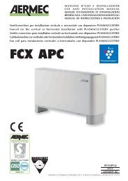
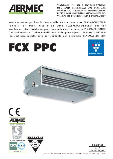
Ventilconvettore per installazione canalizzata con depuratore PLASMACLUSTER®<br />
Fancoil for duct installation with PLASMACLUSTER® purifier<br />
Ventilo-convecteur installation pour canalisation avec dépurateur PLASMACLUSTER®<br />
Gebläsekonvektor Truhenmodelle mit Reinigungsapparat PLASMACLUSTER®<br />
Fan coil para instalaciones por conducto con depurador PLASMACLUSTER®<br />
<strong>FCX</strong> <strong>PPC</strong><br />
ISO 9001 - Cert. n° 0128/4<br />
MANUALE D’USO E INSTALLAZIONE<br />
USE AND INSTALLATION MANUAL<br />
MANUEL D'UTILISATION ET D'INSTALLATION<br />
BEDIENUNGS- UND INSTALLATIONSANLEITUNG<br />
MANUAL DE INSTRUCCIONES E INSTALACIÓN<br />
I<strong>FCX</strong><strong>PPC</strong>LJ<br />
0711<br />
64560.58_02<br />
Sostituisce il Replace Remplace le n° Ersetzt Sustituye a: 64560.58_01 / 0703
Italiano<br />
English<br />
Español Deutsche<br />
Français<br />
INDICE<br />
DICHIARAZIONE DI CONFORMITÀ<br />
Trasporto Simboli di sicurezza<br />
Dati dimensionali<br />
Disegni<br />
Schema elettrico<br />
Plasmacluster Imballo Installazione dell’unità Collegamenti elettrici Rotazione batteria<br />
Informazioni importanti e manutenzione<br />
SOLUZIONE DEI PROBLEMI<br />
SERVIZIO ASSISTENZA TECNICA IN ITALIA<br />
INDEX<br />
DECLARATION OF CONFORMITY<br />
Carriage Safety symbol<br />
Dimensions<br />
Sketches<br />
Wiring diagram<br />
Plasmacluster Packaging Unit installation Electrical connections Battery rotation<br />
Important information and maintenance<br />
TROUBLE SHOOTING<br />
INDEX<br />
CERTIFICAT DE CONFORMITE<br />
Transport Simboles de securite<br />
Dimensions<br />
Dessin<br />
Schemas electriques<br />
Plasmacluster Emballage Installation de l'unité Raccordements électriques Rotation batterie<br />
Informations importantes et entretien<br />
SOLUTION DES PROBLEMES<br />
INDEX<br />
KONFORMITÄTSERKLÄRUNG<br />
Transport Sicherheitssymbole<br />
Abmessungen<br />
Designs<br />
Schaltpläne<br />
Plasmacluster Verpackung Installation der Einheit Elektrische Anschlüsse Umdrehen des Wärmetauschers<br />
Wichtige Informationen und Wartung<br />
PROBLEMLÖSUNG<br />
ÍNDICE<br />
DECLARACIÓN DE CONFORMIDAD<br />
Transporte Símbolos de seguridad<br />
Dimensiones<br />
Diseños<br />
Esquemas eléctricos<br />
Plasmacluster Embalaje Instalación de la unidad Conexiones eléctricas Giro batería<br />
Información importante y mantenimiento<br />
SOLUCIÓN DE PROBLEMAS<br />
3<br />
4<br />
5<br />
8<br />
10<br />
12<br />
13<br />
22<br />
23<br />
3<br />
4<br />
5<br />
8<br />
10<br />
14<br />
15<br />
22<br />
3<br />
4<br />
5<br />
8<br />
10<br />
16<br />
17<br />
22<br />
3<br />
4<br />
5<br />
8<br />
10<br />
18<br />
19<br />
22<br />
3<br />
4<br />
5<br />
8<br />
10<br />
20<br />
21<br />
22
AERMEC S.p.A.<br />
I-37040 Bevilacqua (VR) Italia – Via Roma, 44<br />
Tel. (+39) 0442 633111<br />
Telefax (+39) 0442 93730 – (+39) 0442 93566<br />
www.aermec.com - info@aermec.com<br />
DICHIARAZIONE DI CONFORMITÀ<br />
Noi, fi rmatari della presente, dichiariamo sotto la nostra esclusiva<br />
responsabilità, che il prodotto:<br />
VENTILCONVETTORE<br />
serie <strong>FCX</strong> <strong>PPC</strong><br />
al quale questa dichiarazione si riferisce è conforme alle seguenti norme<br />
armonizzate:<br />
- CEI EN 60335-2-40<br />
- CEI EN 55014-1<br />
- CEI EN 55014-2<br />
- CEI EN 61000-6-1<br />
- CEI EN 61000-6-3<br />
soddisfando così i requisiti essenziali delle seguenti direttive:<br />
- Direttiva LVD 2006/95/CE<br />
- Direttiva compatibilità elettromagnetica 2004/108/CE<br />
- Direttiva Macchine 98/37/CE<br />
<strong>FCX</strong> <strong>PPC</strong> CON ACCESSORI<br />
E’ fatto divieto di mettere in servizio il prodotto dotato di accessori<br />
non di fornitura Aermec.<br />
CERTIFICAT DE CONFORMITÉ<br />
Nous soussignés déclarons sous notre exclusive responsabilité que le<br />
produit:<br />
VENTILO-CONVECTEURS<br />
série <strong>FCX</strong> <strong>PPC</strong><br />
auquel cette déclaration fait référence, est conforme aux normes<br />
harmonisées suivantes:<br />
- EN 60335-2-40<br />
- EN 55014-1<br />
- EN 55014-2<br />
- EN 61000-6-1<br />
- EN 61000-6-3<br />
satisfaisant ainsi aux conditions essentielles des directives suivantes:<br />
- Directive LVD 2006/95/CE<br />
- Directive compatibilité électromagnétique 2004/108/CE<br />
- Directive Machines 98/37/CE<br />
<strong>FCX</strong> <strong>PPC</strong> PLUS ACCESSOIRES<br />
Il est interdit de faire fonctionner l'appareil avec des accessoires qui<br />
ne sont pas fournis de Aermec.<br />
DECLARACIÓN DE CONFORMIDAD<br />
Los que suscriben la presente declaran bajo la propia y exclusiva<br />
responsabilidad que el conjunto en objeto, defi nido como sigue:<br />
FAN COIL<br />
serie <strong>FCX</strong> <strong>PPC</strong><br />
al que esta declaración se refi ere, está en conformidad a las siguientes<br />
normas armonizadas:<br />
- EN 60335-2-40<br />
- EN 55014-1<br />
- EN 55014-2<br />
- EN 61000-6-1<br />
- EN 61000-6-3<br />
al que esta declaración se refi ere, está en conformidad a las siguientes<br />
normas armonizadas:<br />
- Directiva LVD 2006/95/CE<br />
- Directiva compatibilidad electromagnétic 2004/108/CE<br />
- Directiva máquinas 98/37/CE<br />
<strong>FCX</strong> <strong>PPC</strong> CON ACCESORIOS<br />
Está prohibido poner en marcha el producto con accesorios<br />
no suministrados por Aermec.<br />
<strong>FCX</strong> <strong>PPC</strong><br />
CONFORMITY DECLARATION<br />
We the undersigned declare, under our own exclusive responsibility,<br />
that the product:<br />
FAN COIL<br />
<strong>FCX</strong> <strong>PPC</strong> series<br />
to which this declaration refers, complies with the following standardised<br />
regulations:<br />
- EN 60335-2-40<br />
- EN 55014-1<br />
- EN 55014-2<br />
- EN 61000-6-1<br />
- EN 61000-6-3<br />
thus meeting the essential requisites of the following directives:<br />
- Directive LVD 2006/95/CE<br />
- EMC Electromagnetic Compatibility Directive 2004/108/CE<br />
- Machine Directive 98/37/CE<br />
<strong>FCX</strong> <strong>PPC</strong> WITH ACCESSORIES<br />
It is not allowed to use the unit equipped with accessories not supplied<br />
by Aermec.<br />
KONFORMITÄTSERKLÄRUNG<br />
Wir, die hier Unterzeichnenden, erklären auf unsere ausschließlich<br />
Verantwortung, dass das Produkt:<br />
GEBLÄSEKONVEKTOR<br />
der Serie <strong>FCX</strong> <strong>PPC</strong><br />
auf das sich diese Erklärung bezieht, den folgenden harmonisierten Normen<br />
entspricht:<br />
- EN 60335-2-40<br />
- EN 55014-1<br />
- EN 55014-2<br />
- EN 61000-6-1<br />
- EN 61000-6-3<br />
womit die grundlegenden Anforderungen folgender Richtlinien erfüllt<br />
werden:<br />
- Richtlinie LVD 2006/95/CE<br />
- Richtlinie zur elektromagnetischen Verträglichkeit 2004/108/CE<br />
- Maschinenrichtlinie 98/37/CE<br />
<strong>FCX</strong> <strong>PPC</strong> + ZUBEHÖR<br />
Falls das Gerät mit Zubehörteilen ausgerüstet wird, die nicht von<br />
Aermec geliefert werden, ist dessen Inbetriebnahme solange untersagt.<br />
Bevilacqua, 01/10/2007 La Direzione Commerciale – Sales and Marketing Director<br />
Luigi Zucchi
Italiano<br />
English<br />
Español Deutsche<br />
Français<br />
TRASPORTO CARRIAGE TRANSPORT TRANSPORT TRANSPORTE<br />
4<br />
NON bagnare Do NOT wet<br />
CRAINT l’humidité Vor Nässe schützen<br />
NO mojar<br />
Sovrapponibilità: controllare sull’imballo la posizione della freccia per<br />
conoscere il numero di macchine impilabili.<br />
Stacking: control the packing for the arrow position to know the number<br />
of machines that can be stacked.<br />
Empilement: vérifier sur l’emballage la position de la flèche pour connaître<br />
le nombre d’appareils pouvant être empilés.<br />
Stapelung: Anhand der Position des Pfeiles an der Verpackung kontrollieren,<br />
wieviele Geräte stapelbar sind.<br />
Apilamiento: observe en el embalaje la posición de la flecha para saber<br />
cuántos equipos pueden apilarse.<br />
NON trasportare la macchina da soli se il suo peso supera i 35 Kg.<br />
DO NOT handle the machine alone if its weight is over 35 Kg.<br />
NE PAS transporter tout seul l’appareil si son poids dépasse 35 Kg.<br />
Das Gerät NICHT alleine tragen, wenn sein Gewicht 35 Kg überschreitet.<br />
NO maneje los equipos en solitario si pesan más de 35 kg.<br />
SIMBOLI DI SICUREZZA SAFETY SYMBOL SIMBOLES DE SECURITE<br />
SICHERHEITSSYMBOLE SÍMBOLOS DE SEGURIDAD<br />
NON calpestare Do NOT trample<br />
NE PAS marcher sur cet emballage Nicht betreten<br />
NO pisar<br />
6<br />
5<br />
4<br />
3<br />
2<br />
1<br />
NON lasciare gli imballi sciolti durante il trasporto.<br />
Do NOT leave loose packages during transport.<br />
ATTACHER les emballages pendant le transport.<br />
Die Verpackungen nicht ungesichert transportieren.<br />
NO lleve las cajas sueltas durante el transporte.<br />
35Kg<br />
Pericolo: Pericolo: Pericolo!!!<br />
Tensione Organi in movimento<br />
Danger: Danger: Danger!!!<br />
Power supply Movings parts<br />
Danger: Danger: Danger!!!<br />
Tension Organes en mouvement<br />
Gefahr ! Gefahr ! Gefahr!!!<br />
Spannung Rotierende Teile<br />
Peligro: Peligro: Peligro!!!<br />
Tensión Elementos en movimiento
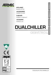
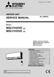
DATI DIMENSIONALI DIMENSIONS DIMENSIONS ABMESSUNGEN DIMENSIONES [mm]<br />
<strong>FCX</strong> 22 - 32 - 42 - 50 <strong>PPC</strong><br />
9 x 20<br />
197<br />
248<br />
25<br />
388<br />
Øe 17,5<br />
9 x 20<br />
110<br />
350<br />
Øe 17,5<br />
50<br />
<strong>FCX</strong> 62 - 82 <strong>PPC</strong><br />
A<br />
B<br />
30 30<br />
C 50<br />
A (<strong>FCX</strong>-P)<br />
C<br />
B<br />
14 14<br />
216<br />
41 101<br />
216<br />
41 107<br />
Mod. <strong>FCX</strong> 22 <strong>FCX</strong> 32 <strong>FCX</strong> 42 <strong>FCX</strong> 50 <strong>FCX</strong> 62 <strong>FCX</strong> 82<br />
A 562 793 1013 1013 1147 1147<br />
B 522 753 973 973 1122 1122<br />
C<br />
Peso<br />
Weight<br />
440 671 891 891 1102 1102<br />
Poids<br />
Gewicht<br />
Peso<br />
kg 13 18 22 22 33 33<br />
Attacchi batteria (femmina) Coil connection (female)<br />
Raccords batterie (femelle) Anschlüsse des Warmetäuschers (Innengewinde)<br />
Conexiones de la batería (hembra)<br />
Mod. <strong>FCX</strong> 22 <strong>FCX</strong> 32 <strong>FCX</strong> 42 <strong>FCX</strong> 50 <strong>FCX</strong> 62 <strong>FCX</strong> 82<br />
3 R 1/2” 1/2” 3/4” 3/4” 3/4” 3/4”<br />
49<br />
144<br />
453<br />
32<br />
253<br />
558<br />
216<br />
96 60<br />
216<br />
96 60<br />
45<br />
85<br />
39<br />
141<br />
5<br />
453<br />
558<br />
Italiano<br />
English<br />
Español Deutsche<br />
Français
Italiano<br />
English<br />
Español Deutsche<br />
Français<br />
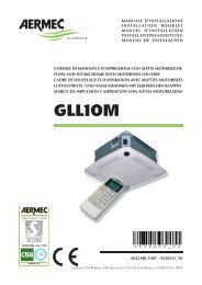
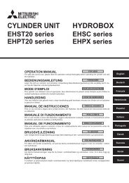
DATI DIMENSIONALI DIMENSIONS DIMENSIONS ABMESSUNGEN DIMENSIONES [mm]<br />
6<br />
<strong>FCX</strong> 22 - 32 - 42 - 50 <strong>PPC</strong><br />
100<br />
min.<br />
Installazione con supporti AMP (accessori) Installation with AMP brackets (accessories)<br />
Installation avec supports AMP (accessories) Installation mit AMP halterung (zubehöre)<br />
Instalación con soportes AMP (accesorios)<br />
36 258 105 258<br />
100<br />
min.<br />
5 5<br />
<strong>FCX</strong> <strong>PPC</strong><br />
A<br />
D C<br />
E<br />
F<br />
B<br />
<strong>FCX</strong> 62 - 82 <strong>PPC</strong><br />
G<br />
24x9<br />
Mod. <strong>FCX</strong> 22 <strong>FCX</strong> 32 <strong>FCX</strong> 42 <strong>FCX</strong> 50 <strong>FCX</strong> 62 <strong>FCX</strong> 82 <strong>PPC</strong><br />
A 750 981 1201 1201 1322 1322<br />
B 555 786 1006 1006 1127 1127<br />
C 600 831 1051 1051 1172 1172<br />
D 95,5 95,5 95,5 95,5 95,5 95,5<br />
E 54,5 54,5 54,5 54,5 54,5 54,5<br />
F 144,5 144,5 144,5 144,5 144,5 144,5<br />
G 103,5 103,5 103,5 103,5 103,5 103,5<br />
In caso di inversione degli attacchi idraulici, scambiare tra loro le seguenti quote: D con E, F con G.<br />
In case of inversion hydraulic connections, invert D with E, F with G.<br />
En cas d’inversion des raccords hydrauliques, inverser les cotes D avec E, F avec G.<br />
Bei der Anschlüßenumstellung, die Quoten D und E, F und G, miteinander auswechseln.<br />
Si desea invertir el lado de las conexiones hidráulicas, intercambie D por E y F por G.
DATI DIMENSIONALI DIMENSIONS DIMENSIONS ABMESSUNGEN DIMENSIONES [mm]<br />
<strong>FCX</strong> 22 ÷ 50 3R <strong>FCX</strong> 62 ÷ 82 3R<br />
404<br />
88<br />
260<br />
153<br />
41<br />
OUT<br />
142<br />
194<br />
IN<br />
Øe 17,5<br />
526<br />
108<br />
273<br />
170<br />
41<br />
OUT<br />
148<br />
194<br />
IN<br />
Øe 17,5<br />
7<br />
Italiano<br />
English<br />
Español Deutsche<br />
Français
Italiano<br />
English<br />
Español Deutsche<br />
Français<br />
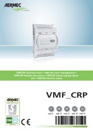
8<br />
B<br />
A<br />
7<br />
11<br />
10<br />
B<br />
A<br />
B<br />
4<br />
A<br />
Fig. 1<br />
Fig. 3<br />
9<br />
1<br />
5<br />
8<br />
6<br />
2<br />
3<br />
1<br />
2<br />
Fig. 2<br />
Fig. 4<br />
Fig. 5
Ø est. 20,5mm<br />
Fig. 6<br />
Fig. 7<br />
Fig. 8<br />
9<br />
Italiano<br />
English<br />
Español Deutsche<br />
Français
Italiano<br />
English<br />
Español Deutsche<br />
Français<br />
SCHEMI ELETTRICI WIRING DIAGRAMS SCHEMAS ELECTRIQUES SCHALTPLÄNE ESQUEMAS ELÉCTRICOS<br />
LEGENDA READING KEY LEGENDE LEGENDE LEYENDA<br />
IG = Interruttore generale Main switch<br />
Interupteur général Hauptschalter Interruptor general<br />
M = Morsettiera Terminal board<br />
Boitier Klemmleiste Caja de conexiones<br />
MS = Microinterruttore Microswitch<br />
Microinterrupteur Mikroschalter Microinterruptor<br />
MV = Motore ventilatore Fan motor Moteur ventilateur<br />
Ventilatormotor Motor ventilador<br />
PE = Collegamento di terra Earth connection<br />
Mise à terre Erdanschluss Toma de tierra<br />
SA = Sonda ambiente Room sensor Sonde ambiante<br />
Raumtemperaturfuhler Sonda ambiente<br />
SC = Scheda di controllo Electronic control board<br />
Platine de contrôle Steuerschaltkreis Tarjeta de control<br />
SW = Sonda minima temperatura acqua<br />
Water low temperature sensor<br />
Sonde eau<br />
Fühler Wassertemperatur<br />
Sonda mínima temperatura del agua<br />
<strong>FCX</strong> <strong>PPC</strong><br />
10<br />
M 1 2 3 4 5 6 7 8 9 10<br />
L N Y N<br />
BL<br />
VC/F<br />
ROS<br />
NE BL<br />
1 3 5 6 7<br />
CLUSTER<br />
5<br />
5<br />
BL NE MA RO<br />
1 2 3 4<br />
1 2 3 4<br />
MAX<br />
MED<br />
MIN<br />
BL NE MA<br />
M<br />
RO<br />
1<br />
MV<br />
6<br />
6<br />
CE<br />
IG<br />
23OV 50Hz<br />
VCF = Valvola solenoide Solenoid valve<br />
Vanne solenoide Magnetventil Válvula solenoide<br />
PE<br />
N<br />
L<br />
SW<br />
= Componenti forniti optional Optional components<br />
Composants en option Optionsteile<br />
Componentes opcionales facilitados<br />
= Collegamenti da eseguire in loco<br />
On-site wiring<br />
Raccordements à effectuer in situ<br />
Vor Ort auszuführende Anschlüsse<br />
Conexiones que deben realizarse in situ<br />
AR = Arancio Orange Orange Orange Naranja<br />
BI = Bianco White Blance Weiss Blanco<br />
BL = Blu Blue Bleu Blau Azul<br />
GR = Grigio Grey Gris Gray Gris<br />
GV = Giallo-Verde Yellow-Green<br />
Jaune-Vert Gelb-Grün Azul-verdoso<br />
MA = Marrone Brown Marron Braun Marrón<br />
NE = Nero Black Noir Schwarz Negro<br />
RO = Rosso Red Rouge Rot Rojo<br />
PXAE<br />
M1<br />
N<br />
L<br />
V1<br />
V2<br />
V3<br />
Y1<br />
Y2<br />
CE<br />
CE<br />
MS<br />
MS<br />
SW<br />
SW<br />
EXT<br />
JP1<br />
INT<br />
-<br />
SA (INT)<br />
Gli schemi elettrici sono soggetti ad un continuo aggiornamento, è obbligatorio quindi fare riferimento a quelli a bordo macchina.<br />
All wiring diagrams are constantly updated. Please refer to the ones supplied with the unit.<br />
Nos schémas électriques étant constamment mis à jour, il faut absolument se référer à ceux fournis à bord de nos appareils.<br />
Die Schaltpläne werden ständig aktualisiert, deswegen muss man sich stets auf das mit dem Gerät gelieferte Schaltschema beziehen.<br />
El cableado de las máquinas es sometido a actualizaciones constantes. Por favor, para cada unidad hagan referencia a los esquemas suministrados con la misma.<br />
+
SCHEMI ELETTRICI WIRING DIAGRAMS SCHEMAS ELECTRIQUES SCHALTPLÄNE ESQUEMAS ELÉCTRICOS<br />
PXAE<br />
M1<br />
F 1A<br />
FC/ 1<br />
FC/ 2<br />
N<br />
L<br />
L PH N N V1 V2 V3 Y1 Y2<br />
INPUT<br />
SIT5<br />
OUTPUT<br />
V3 V2 V1 Y1 Y2<br />
MAX FC/10<br />
+<br />
-<br />
V1<br />
V2<br />
V3<br />
Y1<br />
Y2<br />
CE<br />
CE<br />
MS<br />
MS<br />
F<br />
2A<br />
L = 15m MAX<br />
V1 V2<br />
OUTPUT<br />
V3<br />
SIT3/ 1<br />
V3 V2 V1 N L<br />
NINPUT<br />
PH<br />
F<br />
2A<br />
CE<br />
V1 V2<br />
OUTPUT<br />
V3<br />
SIT3/ 2<br />
L = 100m MAX<br />
V3 V2 V1 N L<br />
NINPUT<br />
PH<br />
MS<br />
MS<br />
SW<br />
SW<br />
SW<br />
EXT<br />
L = 15m MAX<br />
SA (INT)<br />
1 2 3 4 5 6 7 8 9 10<br />
BL NE MA RO<br />
M<br />
JP1<br />
M<br />
1 2 3 4 5 6 7 8 9 10<br />
BL NE MA RO<br />
INT<br />
VC/F VC/F<br />
6<br />
6<br />
1 2 3 4<br />
1 2 3 4<br />
5<br />
5<br />
BL<br />
ROS<br />
L N Y N<br />
6<br />
6<br />
1 2 3 4<br />
1 2 3 4<br />
5<br />
5<br />
BL<br />
ROS<br />
L N Y N<br />
MIN<br />
MED<br />
MAX<br />
MIN<br />
MED<br />
MAX<br />
BL NE MA RO<br />
BL NE MA RO<br />
M<br />
NE BL<br />
M<br />
1 3 5 6 7<br />
1<br />
1<br />
MV MV<br />
1 3 5 6 7<br />
NE BL<br />
FC/ 1<br />
CLUSTER<br />
FC/ 2<br />
CLUSTER<br />
N<br />
L<br />
L N<br />
PE<br />
L N<br />
23OV 50Hz<br />
IG<br />
<strong>FCX</strong> <strong>PPC</strong><br />
SIT5<br />
SIT3<br />
Gli schemi elettrici sono soggetti ad un continuo aggiornamento, è obbligatorio quindi fare riferimento a quelli a bordo macchina.<br />
All wiring diagrams are constantly updated. Please refer to the ones supplied with the unit.<br />
Nos schémas électriques étant constamment mis à jour, il faut absolument se référer à ceux fournis à bord de nos appareils.<br />
Die Schaltpläne werden ständig aktualisiert, deswegen muss man sich stets auf das mit dem Gerät gelieferte Schaltschema beziehen.<br />
El cableado de las máquinas es sometido a actualizaciones constantes. Por favor, para cada unidad hagan referencia a los esquemas suministrados con la misma.<br />
11<br />
Italiano<br />
English<br />
Español Deutsche<br />
Français
Italiano<br />
Conservare i manuali in luogo asciutto, per evitare il deterioramento,<br />
per almeno 10 anni per eventuali riferimenti futuri.<br />
Leggere attentamente e completamente tutte le informazioni<br />
contenute in questo manuale. Prestare particolarmente<br />
attenzione alle norme d’uso accompagnate dalle scritte<br />
“PERICOLO” o “ATTENZIONE” in quanto, se non osservate,<br />
possono causare danno alla macchina e/o a persone e cose.<br />
Per anomalie non contemplate da questo manuale, interpellare<br />
tempestivamente il Servizio Assistenza di zona.<br />
INSTALLAZIONE DELL’UNITÀ<br />
ATTENZIONE: prima di effettuare qualsiasi intervento, assicurarsi<br />
che l’alimentazione elettrica sia disinserita.<br />
ATTENZIONE: i collegamenti elettrici, l’installazione dei ventilconvettori<br />
e dei loro accessori devono essere eseguiti solo<br />
da soggetti in possesso dei requisiti tecnico-professionali di<br />
abilitazione all’installazione, alla trasformazione, all’ampliamento<br />
e alla manutenzione degli impianti ed in grado di verificare<br />
gli stessi ai fini della sicurezza e della funzionalità.<br />
Il ventilconvettore deve essere installato in posizione tale da<br />
consentire facilmente la manutenzione ordinaria (pulizia del<br />
filtro) e straordinaria, nonchè l’accesso alla valvola di sfiato<br />
dell’aria sulla fiancata del telaio (lato attacchi).<br />
Per installare l’unità procedere come segue:<br />
- Estrarre il filtro dell’aria.<br />
- Togliere il pannello di chiusura anteriore nel caso delle versioni<br />
pensili di grandezza da 22 a 50.<br />
- In caso di installazione a parete, si mantenga una distanza<br />
minima dal pavimento di 80 mm. In caso di installazione a<br />
pavimento per mezzo degli zoccoli, si faccia riferimento alle<br />
istruzioni a corredo dell’accessorio.<br />
- Per il fissaggio al muro o al soffitto usare dei tasselli ad espansione<br />
(non forniti) come indicato in Figg. 1 e 2.<br />
Per le versioni pensili, nel caso si utilizzi l’accessorio supporti<br />
(AMP), procedere come segue :<br />
- montare i 4 supporti (1 di Fig. 4) ai lati dell’apparecchio inserendo<br />
nell’apposita feritoia la linguetta superiore e fissando la<br />
COLLEGAMENTI ELETTRICI<br />
ATTENZIONE: prima di effettuare qualsiasi intervento, assicurarsi<br />
che l’alimentazione elettrica sia disinserita.<br />
ATTENZIONE: i collegamenti elettrici, l’installazione dei ventilconvettori<br />
e dei loro accessori devono essere eseguiti solo<br />
da personale specializzato.<br />
CARATTERISTICHE DEI CAVI DI COLLEGAMENTO<br />
Usare cavi tipo H05V-K oppure N07V-K con isolamento<br />
300/500 V incassati in tubo o canalina.<br />
Tutti i cavi devono essere incassati in tubo o canalina finchè<br />
non sono all’interno del ventilconvettore.<br />
I cavi all’uscita dal tubo o canalina devono essere posizionati<br />
in modo da non subire sollecitazioni a trazione o torsione e<br />
comunque protetti da agenti esterni.<br />
Cavi a trefolo possono essere usati solo con capicorda.<br />
Assicurarsi che i trefoli dei fili siano ben inseriti.<br />
Gli schemi elettrici sono soggetti ad un continuo aggiornamento,<br />
è obbligatorio quindi fare riferimento a quelli a bordo<br />
macchina.<br />
Per proteggere l’unità contro i cortocircuiti, montare sulla<br />
linea di alimentazione un interruttore onnipolare magnetotermico<br />
2A 250V (IG) con distanza minima di apertura dei<br />
contatti di 3mm.<br />
I ventilconvettori <strong>FCX</strong> <strong>PPC</strong> richiedono l’abbinamento con<br />
il pannello comandi PXAE (accessorio), per l’installazione e<br />
ROTAZIONE DELLA BATTERIA<br />
Se per motivi di allacciamenti idraulici, si dovesse ruotare la<br />
batteria, dopo aver tolto il pannello di chiusura anteriore, procedere<br />
come segue (Fig. 5):<br />
– togliere la vite (1) che fissa il pannello comandi (2) (se presente)<br />
alla fiancata destra ed estrarlo staccando i collegamenti elettrici;<br />
– togliere la bacinella di raccolta condensa (3);<br />
– togliere il coperchio di chiusura della batteria (4) svitando le viti;<br />
– togliere le viti che fissano la batteria (5) e quindi estrarla;<br />
– rimuovere i semitranciati (6) dalla fiancata destra;<br />
– ruotare la batteria (5) e fissarla con le viti precedentemente tolte;<br />
– rimontare il coperchio (4), fissandolo con le viti, e i tappi in<br />
plastica (7), forniti a corredo, nei fori lasciati liberi dagli attac-<br />
12<br />
L'apparecchio deve essere installato in maniera tale da rendere<br />
possibili operazioni di manutenzione e/o riparazione.<br />
La garanzia dell'apparecchio non copre in ogni caso i costi<br />
dovuti ad autoscale, ponteggi o altri sistemi di elevazione che<br />
si rendesero necessari per effettuare gli interventi in garanzia.<br />
AERMEC S.p.A. declina ogni responsabilità per qualsiasi danno<br />
dovuto ad un uso improprio della macchina, ad una lettura parziale<br />
o superficiale delle informazioni contenute in questo manuale.<br />
Il numero di pagine di questo manuale è: 24.<br />
parte inferiore al frutto per mezzo delle viti a corredo;<br />
- fissare a soffitto le flange (2) mediante tasselli ad espansione<br />
(non forniti); per le posizioni relative tra flange e frutto si vedano<br />
i dati dimensionali.<br />
- Effettuare i collegamenti idraulici.<br />
La posizione e il diametro degli attacchi idraulici sono riportati<br />
nei dati dimensionali.<br />
Si consiglia di isolare adeguatamente le tubazioni dell’acqua o<br />
di installare l’apposita bacinella ausiliaria di raccolta condensa,<br />
disponibile come accessorio, per evitare gocciolamenti durante<br />
il funzionamento in raffreddamento. In caso di installazione<br />
orizzontale, montare il raccordo di scarico della condensa fornito<br />
a corredo secondo quanto illustrato in figura 6. Si abbia cura<br />
di sigillare con silicone la connessione tra bacinella e raccordo.<br />
La rete di scarico della condensa deve essere opportunamente<br />
dimensionata e le tubazioni posizionate in modo da mantenere<br />
lungo il percorso un’adeguata pendenza (min.1%). Nel caso di<br />
scarico nella rete fognaria, si consiglia di realizzare un sifone<br />
che impedisca la risalita di cattivi odori verso gli ambienti.<br />
- Effettuare i collegamenti elettrici secondo quanto riportato<br />
negli schemi elettrici.<br />
- Rimontare l'involucro, o il pannello di chiusura anteriore,<br />
senza dimenticarsi di connettere la sonda ambiente o il<br />
microinterruttore (se presenti).<br />
- Riposizionare il filtro dell’aria.<br />
l’uso prendere visione anche del manuale PXAE.<br />
Ogni pannello comandi può controllare un solo ventilconvettore.<br />
Il luogo di montaggio deve essere scelto in modo che il limite<br />
di temperatura ambiente massimo e minimo venga rispettato<br />
0÷45°C (
INFORMAZIONI IMPORTANTI E MANUTENZIONE<br />
ATTENZIONE: il ventilconvettore è collegato alla rete elettrica<br />
ed al circuito idraulico, un intervento da parte di personale non<br />
provvisto di specifica competenza tecnica può causare danni allo<br />
stesso operatore, all’apparecchio ed all’ambiente circostante.<br />
ALIMENTARE IL VENTILCONVETTORE SOLO CON TENSIO-<br />
NE 230 VOLT MONOFASE<br />
Utilizzando alimentazioni elettriche diverse il ventilconvettore<br />
può subire danni irreparabili.<br />
NON USARE IL VENTILCONVETTORE IN MODO IMPROPRIO<br />
Il ventilconvettore non va utilizzato per allevare, far nascere e<br />
crescere animali.<br />
VENTILARE L'AMBIENTE<br />
Si consiglia di ventilare periodicamente l'ambiente ove è<br />
installato il ventilconvettore, specialmente se nel locale risiedono<br />
parecchie persone o se sono presenti apparecchiature a<br />
gas o sorgenti di odori.<br />
REGOLARE CORRETTAMENTE LA TEMPERATURA<br />
La temperatura ambiente va regolata in modo da consentire il<br />
massimo benessere alle persone presenti, specialmente se si<br />
tratta di anziani, bambini o ammalati, evitando sbalzi di temperatura<br />
tra interno ed esterno superiori a 7 °C in estate.<br />
In estate una temperatura troppo bassa comporta maggiori<br />
consumi elettrici.<br />
ORIENTARE CORRETTAMENTE IL GETTO D'ARIA<br />
L'aria che esce dal ventilconvettore non deve investire direttamente<br />
le persone; infatti, anche se a temperatura maggiore di<br />
quella dell'ambiente, può provocare sensazione di freddo e<br />
conseguente disagio.<br />
NON USARE ACQUA TROPPO CALDA<br />
Per pulire il ventilconvettore usare panni o spugne morbidi<br />
bagnati in acqua al massimo a 40 °C. Non usare prodotti chimici<br />
o solventi per nessuna parte del ventilconvettore. Non spruzzare<br />
acqua sulle superfici esterne o interne del ventilconvettore (si<br />
potrebbero provocare dei corti circuiti).<br />
LIMITI DI FUNZIONAMENTO<br />
Massima temperatura ingresso acqua 80 °C<br />
Massima pressione d'esercizio 8 bar<br />
Minima temperatura media dell’acqua<br />
Per evitare fenomeni di condensazione sulla struttura esterna<br />
dell’apparecchio con ventilatore in funzione, la temperatura<br />
media dell’acqua non deve essere inferiore ai limiti riportati<br />
nella tabella sottostante, che dipendono dalle condizioni<br />
PLASMACLUSTER<br />
La qualità dell’aria trattata è garantita dal sistema di depurazione<br />
“PLASMACLUSTER” che decompone le molecole di<br />
acqua e di ossigeno, normalmente presenti nell’aria ambiente<br />
(“umidità” ed “ossigeno”), in ioni postivi e negativi. Tali ioni<br />
liberati nell’aria andranno ad aderire alle molecole delle<br />
IMBALLO<br />
I ventilconvettori vengono spediti con imballo standard costituito<br />
da gusci di polistirolo espanso e cartone.<br />
PULIRE PERIODICAMENTE IL FILTRO<br />
Una pulizia frequente del filtro garantisce una maggiore ef ficienza<br />
di funzionamento.<br />
Controllare se il filtro risulta molto sporco: nel caso ripetere<br />
l’operazione più spesso.<br />
Pulire frequentemente, togliere la polvere accumulata con un<br />
aspiratore.<br />
Quando il filtro è pulito rimontarlo sul ventilconvettore procedendo<br />
al contrario rispetto allo smontaggio.<br />
PULIZIA STRAORDINARIA<br />
La possibilità di rimuovere le coclee dei ventilatori ispezionabili<br />
(eseguibile solo da personale provvisto di specifica competenza<br />
tecnica) consente di eseguire una pulizia accurata delle<br />
anche delle parti interne, condizione necessaria per installazioni<br />
in luoghi molto affollati o che richiedono uno standard<br />
elevato di igiene.<br />
DURANTE IL FUNZIONAMENTO<br />
Lasciare sempre il filtro montato sul ventilconvettore durante il<br />
funzionamento, altrimenti la polvere presente nell'aria andrà a<br />
sporcare le superfici della batteria.<br />
È NORMALE<br />
Nel funzionamento in raffreddamento può uscire del vapore<br />
acqueo dalla mandata del ventilconvettore.<br />
Nel funzionamento in riscaldamento un leggero fruscio d’aria<br />
può essere avvertibile in prossimità del ventilconvettore.<br />
Talvolta il ventilconvettore può emettere odori sgradevoli dovuti<br />
all'accumulo di sostanze presenti nell'aria dell'ambiente (specialmente<br />
se non si provvede a ventilare periodicamente la<br />
stanza, pulire il filtro più spesso).<br />
Durante il funzionamento si potrebbero avvertire rumori e<br />
scricchiolii interni all'apparecchio dovuti alle diverse dilatazioni<br />
termiche degli elementi (plastici e metallici), ciò comunque non<br />
indica un malfunzionamento e non provoca danni all’unità se non<br />
si supera la massima temperatura dell'acqua di ingresso.<br />
termo-igrometriche dell’aria ambiente.<br />
I suddetti limiti si riferiscono al funzionamento con ventilatore<br />
in moto alla minima velocità.<br />
In caso di prolungata situazione con ventilatore spento e passaggio<br />
di acqua fredda in batteria, è possibile la formazione di<br />
condensa all’esterno dell’apparecchio, pertanto si consiglia<br />
l’inserimento dell’accessorio valvola a tre vie .<br />
MINIMA TEMPERATURA MEDIA ACQUA<br />
Temperatura a bulbo secco dell’aria ambiente °C<br />
21 23 25 27 29 31<br />
15 3 3 3 3 3 3<br />
Temperatura a bulbo umido 17 3 3 3 3 3 3<br />
dell’aria ambiente °C 19 3 3 3 3 3 3<br />
21 6 5 4 3 3 3<br />
23 - 8 7 6 5 5<br />
sostanze inquinanti e ricombinandosi (una volta attivate) le<br />
decompongono in sottoprodotti non tossici (acqua, ossigeno<br />
ed anidride carbonica, etc..).<br />
Il depuratore dell’aria “PLASMACLUSTER” si attiva contemporaneamente<br />
alla ventilazione sia a Caldo che a Freddo.<br />
13<br />
Italiano
English<br />
Store the manuals in a dry location to avoid deterioration, as<br />
they must be kept for at least 10 years for any future reference.<br />
All the information in this manual must be carefully read and<br />
understood. Pay particular attention to the operating standards<br />
with “DANGER” or “WARNING” signals as failure to comply with<br />
them can cause damage to the machine and/or persons or objects.<br />
If any malfunctions are not included in this manual, contact<br />
the local After-sales Service immediately.<br />
The apparatus must be installed in such a way that maintenan-<br />
UNIT INSTALLATION<br />
CAUTION: check that the power supply is disconnected before<br />
performing operations on the unit.<br />
CAUTION: wiring connections installation of the fancoil and<br />
relevant accessories should be performed by a technician who<br />
has the necessary technical and professional expertise to install,<br />
modify, extend and maintain plants and who is able to check the<br />
plants for the purposes of safety and correct operation.<br />
The fancoil should be installed in such a way as to facilitate<br />
routine (filter cleaning) and special maintenance operations,<br />
as well as access to the air breather valve on the side of the<br />
unit frame (connector side).<br />
To install the unit, proceed as follows:<br />
- Extract the air filter.<br />
- Remove the rear cover panel in the case of wall models,<br />
sizes 22 to 50.<br />
- In the case of wall-mounted, keep a minimum clearance of<br />
80 mm from the floor. In the case of floor-mounted units on<br />
bases, refer to the instructions supplied with the accessory.<br />
- Use expansion plugs (not supplied) to secure the unit to the<br />
wall or ceiling, as shown in figures 1 and 2.<br />
To install hanging units with the AMP brackets, proceed as follows:<br />
- fit the 4 brackets (1 in Fig. 4) to the sides of the unit; insert<br />
ELECTRICAL CONNECTIONS<br />
CAUTION: make sure that electrical power to the machine<br />
has been turned off before making electrical connections.<br />
CAUTION: wiring operations and installation of the fancoil<br />
and relative accessories should be performed by specialised<br />
personnel only.<br />
CONNECTION CABLE SPECIFICATIONS<br />
Use H05V-K or N07V-K type with 300/500 V insulation piped<br />
or ducted.<br />
All cables must be piped or ducted until they are not placed<br />
inside the fan coil.<br />
The cables coming out of the pipe/duct must not be subjected to<br />
stretch or twist. They must be protected from weather conditions.<br />
Stranded wires may only be used in connection with terminating<br />
sleeves. It must be ensured that all individual wires are<br />
correctly inserted in the sleeve.<br />
All wiring diagrams are constantly updated. Please refer to the<br />
ones supplied with the unit.<br />
To protect fan coils against short circuits, always fit the power<br />
cable to the units with 2A 250V (IG) thermo-magnetic all-pole<br />
switches with a minimum contact gap of 3 mm.<br />
<strong>FCX</strong> <strong>PPC</strong> fan coils are to be used with PXAE control panel (acces-<br />
ROTATING THE COIL<br />
If connection of utilities to the unit requires rotation of the coil, remove<br />
the front pannel, then proceed as follows (Fig. 5):<br />
– remove the screw (1) securing the control panel (2) (if present)<br />
to the right side of the unit, then remove it after electrical<br />
disconnection;<br />
– remove the condensate tray (3);<br />
– remove the coil cover sheet (4) by removing the screws;<br />
– remove the screws securing the coil (5), then remove it;<br />
– remove the push-outs and the small plate (6) on the right<br />
side;<br />
– rotate the coil (5), then secure it in the new position with the<br />
screws previously removed;<br />
– remount the coil cover sheet (4) and secure it with screws,<br />
then insert the plastic plugs (7) supplied in the openings<br />
left free by the hydraulic connections; after removing the<br />
Plasmacluster use the small plate for closing the hole on the<br />
14<br />
ce and/or repair operations are possible.<br />
The apparatus's warranty does not in any case cover costs due<br />
to automatic ladders, scaffolding or other lifting systems necessary<br />
for carrying out repairs under guarantee.<br />
AERMEC S.p.A. declines all responsibility for any damage whatsoever<br />
caused by improper use of the machine, and a partial<br />
or superficial acquaintance with the information contained in<br />
this manual.<br />
The number of pages in this manual is : 24.<br />
the upper tab in the slot, then secure the lower part to the<br />
contact block by means of the screws supplied;<br />
- secure the flanges (2) to the ceiling by means of expansion<br />
plugs (not supplied); for the positions between the flanges and<br />
the contact block, see the dimensional data.<br />
- Make hydraulic connections.<br />
Refer to the dimensional data for the position and diameter of<br />
the hydraulic connectors.<br />
Insulate water lines adequately or fit the condensate drainage<br />
tray (available as an accessory) to prevent dripping during<br />
cooling applications. In case of horizontal installation, fit the<br />
condensate discharge pipe (supplied separately) following the<br />
indications shown in picture 6. The connection between pipe<br />
and drip tray must be sealed with silicone.<br />
The condensate drainage system should be of an adequate size<br />
and be positioned to favour runoff (min. 1% slope). If condensate<br />
is discharged into the sewage system, install a siphon to<br />
prevent return of unpleasant odour into the room.<br />
- Make the electrical connections as shown in the wiring diagrams.<br />
- Remount the cover, or the front pannel, connect the ambient<br />
sensor or the microswitch (if present).<br />
- Refit the air filter.<br />
sory). Please consult the PXAE booklet for installation and use<br />
Each control panel can control a single fancoil.<br />
The assembling place must be chosen so that the max. and<br />
min. room temperature limit is respected 0÷45°C (
IMPORTANT MAINTENANCE INFORMATION<br />
WARNING: The fancoil is connected to the power supply and<br />
a water circuit. Operations performed by persons without<br />
the required technical skills can lead to personal injury to the<br />
operator or damage to the unit and surrounding objects.<br />
POWER THE FANCOIL WITH SINGLE-PHASE 230 V ONLY<br />
Use of other power supplies could cause permanent damage to<br />
the fancoil.<br />
NEVER USE THE FANCOIL FOR APPLICATIONS FOR WHICH<br />
IT WAS NOT DESIGNED<br />
Do not use the fancoil in husbandry applications (e.g. incubation).<br />
AIR THE ROOM<br />
Periodically air the room in which the fancoil has been installed;<br />
this is particularly important if the room is occupied by<br />
many people, or if gas appliances or sources of odours are<br />
present.<br />
CORRECTLY ADJUST THE TEMPERATURE<br />
Room temperature should be regulated to ensure maximum<br />
comfort to persons present, particularly in the case of the<br />
elderly, infants and invalids. Prevent temperature fluctuations<br />
between indoors and outdoors greater than 7 °C during summer.<br />
Note that very low temperatures during summer will lead to<br />
greater electricity consumption.<br />
ORIENT AIR FLOW CORRECTLY<br />
Air delivered by the fancoil should not be oriented directly at<br />
people; even if air temperature is greater than room temperature,<br />
it can cause a cold sensation and consequently discomfort.<br />
DO NOT USE HOT WATER<br />
When cleaning the indoor unit, use rags or soft sponges soaked<br />
in warm water (no higher than 40°C).<br />
Do not use chemical products or solvents to clean any part of<br />
the fancoil.<br />
OPERATING LIMITS<br />
Maximum water inlet temperature 80 °C<br />
Maximum working pressure 8 bar<br />
Minimum average water temperature<br />
To prevent the formation of condensation on the exterior<br />
of the unit while the fan is operating, the average water<br />
temperature should not drop beneath the limits shown in<br />
the table below, determined by the ambient conditions.<br />
PLASMACLUSTER<br />
The quality of the air treated is guaranteed by the<br />
“PLASMACLUSTER” purifier that breaks down the water and<br />
oxygen molecules , normally present in the air in the room<br />
(“humidity” and “oxygen”), in positive and negative ions.<br />
These ions liberated into the air will stick to the molecules of<br />
PACKING<br />
The units are shipped in cardboard box standard packing and<br />
polystirene shells.<br />
Do not splash water on interior or exterior surfaces of the fancoil;<br />
danger of short circuit.<br />
PERIODICALLY CLEAN THE FILTER<br />
Frequent cleaning of the filter will ensure more efficient unit<br />
operation.<br />
Check whether the filter requires cleaning; if it is particularly<br />
dirty, clean it more often.<br />
Clean the filter frequently. Use a vacuum cleaner to remove<br />
built up dust. Avoid water or detergents if possible since they<br />
greatly accelerate loss of the filter's electrostatic charge.<br />
After cleaning and drying the filter, fit it on the fancoil by following<br />
the removal procedure in reverse order.<br />
SPECIAL CLEANING<br />
The removable drip tray and fan volute ensure thorough cleaning<br />
of the unit (by specifically trained personnel), essential<br />
for installations in venues subject to crowding or in those with<br />
special hygiene requirements.<br />
DURING UNIT OPERATION<br />
Always leave the filter on the fancoil during operation (otherwise<br />
dust in the air could soil the surface of the coil).<br />
IT IS NORMAL<br />
During cooling, water vapour may be present in the air delivery.<br />
During heating operation a light rustling sound may be perceived<br />
near the fancoil.<br />
Sometimes the fancoil can give off unpleasant odours due to<br />
the accumulation of substances present in the room: air the<br />
room and clean the filter more often.<br />
During the operation, there could be noises and creaks inside<br />
the device, due to the various heat expansions of the elements<br />
(plastic and metallic), but this does not indicate any malfunctioning<br />
and does not cause damage to the unit unless the maximum<br />
input water temperature is exceeded.<br />
These limits refer to unit operation with fan at minimum speed.<br />
Note that condensation may form on the exterior of the unit if<br />
cold water circulates through the coil while the fan is off for<br />
prolonged periods of time, so it is advisable to fit the additional<br />
three-way valve.<br />
MINIMUM AVERAGE WATER TEMPERATURE<br />
Dry bulb temperature °C<br />
21 23 25 27 29 31<br />
15 3 3 3 3 3 3<br />
17 3 3 3 3 3 3<br />
Wet bulb temperature °C 19 3 3 3 3 3 3<br />
21 6 5 4 3 3 3<br />
23 - 8 7 6 5 5<br />
the polluting substances and by being recombined (once activated)<br />
decomposes them into non-toxic sub-products (water,<br />
oxygen and carbon dioxide etc..).<br />
The “PLASMACLUSTER” air purifier is activated at the same<br />
time as the ventilation when both hot and cold.<br />
15<br />
English
Français<br />
Conserver les manuels dans un endroit sec, afin d’éviter leur<br />
détérioration, pendant au moins 10 ans, pour toutes éventuelles<br />
consultations futures.<br />
Lire attentivement et entièrement toutes les informations contenues<br />
dans ce manuel. Prêter une attention particulière aux<br />
normes d’utilisation signalées par les inscriptions “DANGER” ou<br />
“ATTENTION”, car leur non observance pourrait causer un dommage<br />
à l’appareil et/ou aux personnes et objets.<br />
Pour toute anomalie non mentionnée dans ce manuel, contacter<br />
aussitôt le service après-vente de votre secteur.<br />
INSTALLATION DE L’UNITE<br />
ATTENTION !: avant d’effectuer une intervention quelconque<br />
s’assurer que l’alimentation électrique est bien désactivée.<br />
ATTENTION: les raccordements électriques, l’installation des<br />
ventiloconvecteurs et de leurs accessoires ne doivent être exécutés<br />
que par des personnes en possession de la qualification<br />
technico-professionnelle requise pour l’habilitation à l’installation,<br />
la transformation, le développement et l’entretien des<br />
installations, et en mesure de vérifier ces dernières aux fins de<br />
la sécurité et de la fonctionnalité.<br />
Le ventiloconvecteur doit être installé dans une position permettant<br />
d'effectuer aisément la maintenance ordinaire (nettoyage du<br />
filtre) et extraordinaire et d'accéder à la soupape d'évent de l'air<br />
sur le côté du châssis (côté raccords).<br />
Pour installer l'unité, procéder comme suit :<br />
- Retirer le filtre de l'air.<br />
- Retirer le panneau de fermeture avant dans le cas des versions<br />
suspendues dans les modèles de 22 à 50.<br />
- En cas d'installation murale, maintenir une distance minimum<br />
au sol de 80 mm. En cas d'installation au sol au moyen des pieds,<br />
faire référence aux instructions accompagnant l'accessoire.<br />
- Pour la fixation au mur ou sur plafond, utiliser des chevilles à<br />
expansion (non livrées) comme indiqué sur les Fig. 1 et 2.<br />
Pour les versions suspendues, si on utilise l'accessoire supports<br />
(AMP), procéder comme suit:<br />
- monter les 4 supports (1 Fig. 4) sur les côtés de l'appareil en<br />
RACCORDEMENTS ELECTRIQUES<br />
ATTENTION: avant d’effectuer une quelconque intervention,<br />
s’assurer que l’alimentation électrique est coupée.<br />
ATTENTION: les raccordements électriques, l'installation des<br />
ventiloconvecteurs et de leurs accessoires ne doivent être exécutés<br />
que par du personnel spécialisé.<br />
CARACTERISTIQUES DES CABLES DE RACCORDEMENT<br />
Utiliser des câbles du type H05V-K ou N07V-K avec isolation<br />
300/500 V en une conduite ou une goulotte.<br />
Tous les câbles doivent être insérés dans des conduites ou goulottes<br />
tant qu'ils se trouvent à l'intérieur du ventilo-convecteur.<br />
A la sortie de la conduite ou de la goulotte, les câbles doivent<br />
être positionnés de façon à ne subir aucune sollicitation telles<br />
que tractions ou torsions et de toutes façons ils doivent être<br />
protégés des agents atmosphériques.<br />
Les câbles tressés doivent être seulement utilisés pour des terminaux<br />
avec douilles. Il faut s’assurer que chaque fil de la tresse<br />
soit correctement inséré dans la douille.<br />
Nos schémas électriques étant constamment mis à jour, il faut<br />
absolument se référer à ceux fournis à bord de nos appareils.<br />
Pour protéger l'unité contre les courts-circuits, montez sur la ligne d'alimentation<br />
un interrupteur omnipolaire magnétothermique 2A 250V<br />
(IG) avec une distance minimum d'ouverture des contacts de 3 mm.<br />
Les ventiloconvecteurs <strong>FCX</strong> <strong>PPC</strong> doivent etre raccordés à un<br />
panneau de commande PXAE (accessoire) pour l’installation et<br />
ROTATION DE LA BATTERIE<br />
Si pour des raisons de raccordements hydrauliques, on doit<br />
retourner la batterie, après avoir enlevé le panneau de fermeture<br />
avant , procéder comme suit :<br />
- Enlever la vis (1) qui fixe le panneau de commande (2) (si présent)<br />
à la façade droite et le retirer en débranchant les cables électriques.<br />
- Déposer le bac des condensats (3).<br />
- Déposer le capot supérieur de la batterie (4) en enlevant les vis.<br />
- Enlever les vis de fixation de la batterie (5) et la déposer.<br />
- Enlever les pastilles prédécoupées et la plaquette (6) du coté gauche.<br />
- Retourner la batterie (5) et la fixer avec ses vis précédemment<br />
retirées.<br />
- Remonter le capot supérieur (4) avec ses vis et les bouchons en<br />
plastique (7) fournis de série dans les trous laissés libres par les rac-<br />
16<br />
Lors de l'installation de l'appareil, il faut prévoir l'espace nécessaire<br />
pour les opérations d'entretien et/ou de réparation.<br />
La garantie de l'appareil ne couvre pas les coûts dérivant de l'utilisation<br />
de voitures avec échelle mécanique, d'échafaudages ou<br />
d'autres systèmes de levée employés pour effectuer des interventions<br />
en garantie.<br />
AERMEC S.p.A. décline toute responsabilité pour tout dommage<br />
dû à une utilisation impropre de l’appareil et à une lecture partielle<br />
ou superficielle des informations contenues dans ce manuel.<br />
Ce manuel se compose de pages: 24.<br />
introduisant la languette supérieure dans la fente prévue à cet<br />
effet et en fixant la partie inférieure au châssis à l'aide des vis<br />
fournies de série;<br />
- fixer les brides (2) sur le plafond à l'aide de chevilles à expansion<br />
(non livrées); pour les positions relatives entre brides et<br />
châssis, voir les dimensions.<br />
- Effectuer les raccordements hydrauliques.<br />
La position et le diamètre des raccords hydrauliques sont indiqués<br />
dans les dimensions.<br />
Il est conseillé d'isoler correctement les tuyauteries de l'eau ou d'installer<br />
le bac auxiliaire de récupération de la condensation, disponible comme<br />
accessoire, pour éviter les égouttements durant le fonctionnement en<br />
refroidissement. En cas d’installation horizontale, monter le raccord<br />
d’écoulement des condensats fourni avec l’appareil comme le montre<br />
la fig.6. Il faudra avoir soin de scéller avec du silicone le raccordement<br />
entre le bac et le raccord. Le réseau d’évacuation de la condensation<br />
doit être convenablement dimensionné et les tuyauteries positionnées<br />
de façon à maintenir une pente correcte (min. 1%) le long du parcours.<br />
En cas d’évacuation dans les égouts, il est conseillé de réaliser un siphon<br />
empêchant les mauvaises odeurs de remonter dans les locaux.<br />
- Effectuer les raccordements électriques comme indiqué sur les<br />
schémas électriques.<br />
- Remonter la carrosserie sans oublier de brancher la sonde de température<br />
ambiante ou le micro-interrupteur (s’ils sont présents).<br />
- Remettre le filtre de l’air.<br />
l’utilisation se rèférer au manuel d’utilisation du PXAE.<br />
Chaque panneau de commande peut contrôler un seul ventiloconvecteur.<br />
Le lieu de montage doit être choisi d’une façon que la limite de temperature<br />
ambient max. et min. soit respectée 0÷45°C (
INFORMATIONS IMPORTANTES SUR LA MAINTENANCE<br />
Le ventilo-convecteur est connecté au réseau électrique et<br />
au circuit hydraulique: l'intervention d'un personnel sans<br />
compétence technique spécifique peut entraîner des blessures<br />
pour l'opérateur ou endommager l'appareil ou le milieu<br />
intéressé.<br />
ALIMENTER LE VENTILO-CONVECTEUR EXCLUSIVEMENT<br />
AVEC UNE TENSION DE 230 VOLTS MONOPHASE<br />
Si l'on utilise des alimentations électriques différentes, le ventilo-convecteur<br />
peut être irrémédiablement endommagé.<br />
NE PAS UTILISER LE VENTILO-CONVECTEUR DE MANIERE<br />
IMPROPRE.<br />
Le ventilo-convecteur ne doit pas être utilisé pour l'élevage, la<br />
naissance ou la croissance d'animaux.<br />
VENTILER LE LOCAL<br />
Nous conseillons de ventiler périodiquement le local où est<br />
installé le ventilo-convecteur, plus spécialement si plusieurs<br />
personnes résident dans le local ou si des appareillages à gaz<br />
ou des sources d'odeurs se trouvent dans le local.<br />
REGLER CORRECTEMENT LA TEMPERATURE<br />
La température ambiante doit être réglée de manière à permettre<br />
le bien-être maximal des personnes présentes, en particulier s'il<br />
s'agit de personnes âgées, d'enfants ou de personnes malades,<br />
en évitant des écarts de température -entre l'intérieur et l'extérieur-<br />
supérieurs à 7 °C en été. En été une température trop<br />
basse entraîne une consommation d'électricité plus importante.<br />
ORIENTER CORRECTEMENT LE JET D'AIR<br />
L'air qui sort du ventilo-convecteur ne doit pas frapper directement<br />
les personnes ; en effet, même si ce jet est à une température<br />
supérieure à celle du local, il peut provoquer une<br />
sensation de froid et donc de malaise.<br />
NE PAS UTILISER DE L'EAU TROP CHAUDE<br />
Pour nettoyer l'intérieur de l'Unité utiliser des chiffons ou des<br />
éponges souples et mouillés avec de l'eau dont la température<br />
maximale ne dépasse pas 40 °C. N'utiliser aucun produit<br />
chimique ou solvant pour nettoyer une partie quelconque du<br />
ventilo-convecteur. Ne pas asperger avec de l'eau les surfaces<br />
externes ou internes du ventilo-convecteur (on pourrait provo-<br />
LIMITES DE FONCTIONNEMENT<br />
Température maximale d'entrée de l'eau 80 °C<br />
Pression maximale de fonctionnement 8 bar<br />
Température minimale moyenne de l’eau<br />
Pour éviter les phénomènes de condensation sur la structure<br />
externe de l'appareil avec le ventilateur en service, la température<br />
moyenne de l'eau ne doit pas être inférieure aux limites<br />
reprises sur le tableau ci-après, qui dépendent des conditions<br />
thermo-hygrométriques de l'air ambiant. Ces limites se réfèrent<br />
PLASMACLUSTER<br />
La qualité de l'air traité est garantie grâce à au système de<br />
dépuration “PLASMACLUSTER” qui décompose les molécules<br />
d'eau et d'oxygène qui sont normalement présentes dans l'air<br />
ambiant (“humidité” et “oxygène”), en ions positifs et négatifs.<br />
Ces ions libérés dans l'air adhéreront aux molécules des sub-<br />
EMBALLAGE<br />
Les convecteurs soufflants sont expédiés dans un emballage standard<br />
composé de coques en polystyrène expansé et en carton.<br />
quer des courts-circuits).<br />
NETTOYER LE FILTRE PERIODIQUEMENT<br />
Un nettoyage fréquent du filtre garantit une meilleure efficacité<br />
de fonctionnement.<br />
Contrôler si le filtre est sale: répéter l'opération plus souvent si<br />
nécessaire.<br />
Nettoyez fréquemment, enlevez la poussière qui s'accumule<br />
avec un aspirateur.<br />
Le remonter sur le ventilo-convecteur en adoptant la procédure<br />
inverse de celle du démontage.<br />
NETTOYAGE EXTRAORDINAIRE<br />
La possibilité d'enlever les vis sans fin des ventilateurs qui<br />
peuvent être inspectés (une opération qui doit être réalisée<br />
uniquement par un personnel doté d'une expérience technique)<br />
permettent d'effectuer un nettoyage soigné des organes<br />
internes également, une condition nécessaire pour une mise en<br />
place dans des locaux très fréquentés ou qui exigent un standard<br />
d'hygiène élevé.<br />
DURANT LE FONCTIONNEMENT:<br />
Laisser toujours le filtre monté sur le ventilo-convecteur durant<br />
le fonctionnement : la poussière qui se trouve dans l'air pourrait,<br />
dans le cas contraire, salir les surfaces de la batterie.<br />
IL EST NORMAL<br />
que durant la fonction de refroidissement, de la vapeur d'eau<br />
soit refoulée du ventilo-convecteur.<br />
Durant le fonctionnement pour le chauffage, une légère brise<br />
d'air peut être perçue à proximité du ventilo-convecteur.<br />
Quelquefois le ventilo-convecteur peut émettre des odeurs<br />
désagréables dues à l'accumulation de substances présentes<br />
dans l'air ambiant (plus spécialement si le local n'est pas périodiquement<br />
ventilé ; nettoyer le filtre plus souvent).<br />
Durant le fonctionnement on peut entendre des bruits et des<br />
craquements internes dus aux différentes dilatations thermiques<br />
des éléments (en plastique ou en métal), cela n’indique<br />
pas un dysfonctionnement et ni ne provoque aucun dommage<br />
à l’unité si l’on ne dépasse pas la température maximale de<br />
l’eau en entrée.<br />
au fonctionnement avec un ventilateur en mouvement à la<br />
vitesse minimale. En cas de situation prolongée avec le ventilateur<br />
éteint et le passage de l'eau froide dans la batterie, de la<br />
buée peut se former à l'extérieur de l'appareil , il est conseillé<br />
d'insérer l'accessoire vanne 3 voies.<br />
TEMPÉRATURE MINIMUM MOYENNE DE L’EAU<br />
Température bulbe sèche °C<br />
21 23 25 27 29 31<br />
15 3 3 3 3 3 3<br />
17 3 3 3 3 3 3<br />
Température bulbe humide °C 19 3 3 3 3 3 3<br />
21 6 5 4 3 3 3<br />
23 - 8 7 6 5 5<br />
stances polluantes et en se recombinant (une fois activées) les<br />
décomposent en sous-produits non toxiques (eau, oxygène et<br />
anhydride carbonique, etc..).<br />
Le dépurateur de l'air“PLASMACLUSTER” s'active en même<br />
temps que la ventilation aussi bien à chaud qu'à froid.<br />
17<br />
Français
Deutsche<br />
Bewahren Sie die Gebrauchsanleitungen mindestens 10 Jahre für<br />
eventuelles zukünftiges Nachschlagen an einem trockenen Ort auf.<br />
Alle in diesem Handbuch enthaltenen Informationen aufmerksam<br />
und vollständig lesen. Insbesondere auf die<br />
Benutzungsanweisungen mit den Hinweisen "VORSICHT" oder<br />
"ACHTUNG" achten, da deren Nichtbeachtung Schäden am<br />
Gerät bzw. Sach- und Personenschäden zur Folge haben kann.<br />
Bei Betriebsstörungen, die in dieser Gebrauchsanweisung nicht aufgeführt<br />
sind, wenden Sie sich umgehend an die zuständige Kundendienststelle.<br />
INSTALLATION DER EINHEIT<br />
ACHTUNG: Vergewissern Sie sich, dass die Stromversorgung des<br />
Gerätes unterbrochen ist, bevor Sie Eingriffe an demselben vornehmen.<br />
ACHTUNG: Der Stromanschluß sowie die Installation der<br />
Gebläsekonvektoren und deren Zubehörteile darf nur von<br />
qualifizertem Fachpersonal durchgeführt werden, das die<br />
technisch-professionellen Fähigkeiten für die Installation, den<br />
Umbau, die Erweiterung und die Wartung von Anlagen besitzt<br />
und fähig ist, solche Anlagen auf Sicherheitsanforderungen und<br />
Funktionstüchtigkeit zu überprüfen.<br />
Der Einbau des Gebläsekonvektors soll die regelmäßige<br />
(Filterreinigung) und außerplanmäßige Wartung sowie den<br />
Zugriff des Entlüftungsventils auf Rahmenseite (Anschlußseite)<br />
problemlos gestatten.<br />
Die Einheit wird folgendermaßen installiert:<br />
- Luftfilter ausziehen.<br />
- Gehäuse bzw. vordere Abdeckung in Deckenmodellen Größe<br />
22 bis 50 durch Losdrehen der Schrauben abnehmen.<br />
- Bei Wandinstallation ist eine Bodenhöhe von mindestens 80<br />
mm vorgeschrieben. Für Bodeninstallationen auf Sockel wird auf<br />
die beiliegenden Zubehöranleitungen verwiesen.<br />
- Zur Wand- und Deckenbefestigung mit (nicht beigestellten)<br />
Dübeln gemäß Abb. 1, 2 vorgehen.<br />
Bei Deckenmodellen mit Zubehör AMP wie folgt verfahren:<br />
- die 4 Halter (1 in Abb. 4) mit der oberen Lasche in den ent-<br />
ELEKTRISCHE ANSCHLÜSSE<br />
ACHTUNG: vor dem Beginn der Arbeiten überprüfen, ob die<br />
Stromversorgung abgeschaltet ist.<br />
ACHTUNG: der Stromanschluss sowie die Installation der<br />
Gebläsekonvektoren und deren Zubehörteile darf nur von qualifiziertem<br />
Fachpersonal durchgeführt werden.<br />
MERKMALE DER ANSCHLUSSKABEL<br />
Bei Verlegung im Rohr oder im Kanal Kabel vom Typ H05V-K oder<br />
N07V-K mit Isolierung 300/500 V verwenden.<br />
Alle Kabel bis zum Gebläsenkonvektor müßen im Rohr oder im<br />
Kanal eingelassen sein.<br />
Die Kabel, die vom Rohr oder vom Kanal ausgehen, müßen unter<br />
keine Zugkraft oder Drehung untergestellt sein und auf jeden Fall<br />
müßen sie gegen Witterungseinflüsse geschützt sein.<br />
Litzen dürfen nur in Verbindung mit Aderendhülsen verwendet<br />
werden. Dabei ist sicherzustellen, dass sich alle Litzendrähte sauber<br />
in der Hülse befinden.<br />
Die Schaltpläne werden ständig aktualisiert, deswegen muss man<br />
sich stets auf das mit dem Gerät gelieferte Schaltschema beziehen.<br />
Um die Einheit vor Kurzschlüssen zu schützen, ist ein allpoliger<br />
FI-Schalter 2A 250V (IG) mit einem Mindestabstand<br />
der Kontaktöffnung von 3mm in der Netzleitung zu montieren.<br />
Die passende Fernbedienung für die Gebläsekonvektoren <strong>FCX</strong> <strong>PPC</strong><br />
ist das Mod. PXAE (als Zubehör erhältlich- siehe bitte entsprechende<br />
IDREHEN DER BATTERIE<br />
Ist bedingt durch die Anordnung der Wasseranschlüsse die<br />
Drehung der Batterie erforderlich, ist nach Wegnahme der<br />
Verkleidung wie folgt zu verfahren (Abb. 5):<br />
– Die Schraube lösen (1), die das Schaltfeld (2) (falls vorgesehen) an<br />
der rechten Seite befestigt und es durch Trennen der elektrischen<br />
Anschlüsse herausziehen;<br />
– das Schutzblech der Batterie und, falls vorhanden, die<br />
Kondensatauffangschale abnehmen (3);<br />
– das Batterieverschlußblech (4) durch Lösen der Schrauben abnehmen;<br />
– die Befestigungsschrauben (5) der Batterie lösen und sie herausnehmen;<br />
– die Vorstanzungen und das viereckige Abdeckblech (6) von der<br />
rechten Seite abnehmen;<br />
– die Batterie (5) drehen und mit den zuvor abgenommenen<br />
Schrauben befestigen;<br />
– das Verschlußblech (4) wieder anbringen und mit den Schrauben<br />
befestigen, die mitgelieferten Plastikstöpsel (7) in die freigewordenen<br />
Öffnungen einsetzen; das viereckige Abdeckblech in die durch<br />
18<br />
Das Gerät so aufstellen, dass Instandhaltungs- und/oder<br />
Reparaturarbeiten durchgeführt werden können.<br />
Die Garantie des Gerätes deckt in keinem Fall Kosten für<br />
Feuerwehrleitern, Gerüste oder andere Hebesysteme ab, die sich<br />
für die Garantiearbeiten als erforderlich erweisen sollten.<br />
Die AERMEC S.p.A. übernimmt keine Haftung für Schäden aus dem<br />
unsachgemäßen Gebrauch des Gerätes und der teilweisen oder oberflächlichen<br />
Lektüre der in diesem Handbuch enthaltenen Informationen.<br />
Die Seitenanzahl diese Handbuches ist: Nr. 24 Seiten<br />
sprechenden Schlitz einschieben, die Unterseite mit den mitgelieferten<br />
Schrauben am Innenteil anschrauben<br />
- Flansche (2) mit (nicht beigestellten) Dübeln an der Decke<br />
befestigen. Daten zur relativen Position von Flanschen und<br />
Innenteil finden Sie unter Abmessungen.<br />
- Wasseranschlüsse vornehmen.<br />
Lage und Durchmesser der Wasseranschlüsse, vgl.<br />
Abmessungen.<br />
Wasserleitungen entsprechend isolieren bzw. zusätzliche<br />
Kondensatwanne (Sonderzubehör) zum Tropfschutz im<br />
Kühlbetrieb installieren.<br />
Bei horizontaler Installation, die separatmitgelieferte<br />
Verschraubung für den Kondensatablass wie nach Abb. 6 montieren.<br />
Bitte die Verbindung Kondensatwanne - Verschraubung<br />
mit Silicon versiegeln. Das Kondensatablaßnetz muß genau<br />
bemessen und die Leitungen so verlegt werden, daß während<br />
des gesamten Verlaufs eine ausreichende Neigung (min.<br />
1%) vorhanden ist. Bei Ablaß in das Abwassernetz wird die<br />
Ausführung eines Siphons empfohlen, der das Hochsteigen<br />
unangenehmer Gerüche in die Räume vermeidet .<br />
- Die Stromanschlüsse wie in den Schaltplänen dargestellt ausführen.<br />
- Die Verkleidung wieder anbringen, den Raumfühler oder den<br />
Mikroschalter (falls vorhanden) anschließen.<br />
- Den Luftfilter wieder einsetzen.<br />
Installations- und Bedienungsanleitung).<br />
Jedes Bedienfeld dient zur Steuerung nur eines Gebläsekonvektors.<br />
Der Montage-Ort muss so gewählt sein, dass die obere Arbeitstemperatur-<br />
Grenze nicht überschritten und die unterer Arbeitstemperatur-Grenze<br />
nicht unterschritten wird 0÷45°C (
WICHTIGE HINWEISE UND WARTUNG<br />
ACHTUNG: der Gebläsekonvektor ist sowoul an das<br />
Stromnetz wie auch an die Wasserversorgung angeschlossen;<br />
Eingriffe durch Personen ohne spezifische technische<br />
Fachkenntnisse können zu Personenverletzungen und zu<br />
Maschinen- und Umweltschäden führen.<br />
DER GEBLÄSEKONVEKTOR DARF NUR MIT<br />
WECHSELSPANNUNG 230 VOLT BETRIEBEN WERDEN<br />
Jede andere Netzspannung kann zu nicht wiedergutzumachenden<br />
Schäden des Gebläsekonvektors führen.<br />
DEN GEBLÄSEKONVEKTOR NIE AUF UNZULÄSSIGE WEISE<br />
VERWENDEN<br />
Der Gebläsekonvektor darf nicht für die Aufzucht von Tieren<br />
eingesetzt werden.<br />
RAUMBELÜFTUNG<br />
Es wird empfohlen, den Raum, in dem der Gebläsekonvektor<br />
installiert wird, regelmäßig zu lüften, ganz besonders<br />
wenn der Raum stark frequentiert wird oder Gasgeräte und<br />
Geruchsquellen vorhanden sind.<br />
KORREKTE TEMPERATUREINSTELLUNG<br />
Die Raumtemperatur sollte so eingestellt werden, dass maximales<br />
Wohlbefinden der anwesenden Personen gewährleistet<br />
ist; im Sommer sollten Temperaturunterschiede von mehr als<br />
7°C zwischen Innen und Außen vermieden werden, ganz<br />
besonders für ältere Personen, Kranke und Kinder. Zu niedrige<br />
Temperaturen im Sommer führen außerdem zu einem erhöhten<br />
Energieverbrauch.<br />
KORREKTE EINSTELLUNG DES LUFTSTROMS<br />
Der vom Gebläsekonvektor kommende Luftstrom sollte<br />
nicht direkt auf die Personen gerichtet sein; selbst wenn die<br />
Temperatur des Luftstroms höher als die des Raums ist, kann er<br />
Kälteempfinden und Unbehagen verursachen.<br />
NIE ZU WARMES WASSER BENUTZEN<br />
Das Innere der Einheit mit einem in warmem Wasser angefeuchteten<br />
(max. 40 °C) Lappen oder Schwamm reinigen. Nie<br />
chemische Produkte oder Lösemittel für die Reinigung des<br />
Gebläsekonvektors verwenden. Nie Wasser auf die Außenoder<br />
Innenflächen des Gerätes spritzen (Kurzschlussgefahr).<br />
GRENZWERTE FÜR DEN GERÄTEBETRIEB<br />
Maximale Wassereintrittstemperatur 80 °C<br />
Maximaler Betriebsdruck 8 bar<br />
Minimale mittlere Wassertemperatur<br />
Zur Vermeidung von Kondenswasserbildung auf der<br />
Geräteaußenseite während des Gebläsebetriebs darf die durchschnittliche<br />
Wassertemperatur nicht niedriger als die in der<br />
unten stehenden Tabelle aufgeführten Grenzwerte sein, die<br />
von den thermohygrometrischen Raumbedingungen abhängen.<br />
PLASMACLUSTER<br />
Die Qualität der aufbereiteten Luft vom Reinigungssystem<br />
“PLASMACLUSTER” eindringen können, dass die Wasser- und<br />
Sauerstoffmoleküle in positive und negative Ionen zerlegt, die<br />
normalerweise in der Raumluft vorhanden sind ("Feuchtigkeit"<br />
und "Sauerstoff"). Diese in der Luft freigesetzten Ionen haften an<br />
den verschmutzenden Substanzen und zersetzen diese, nach<br />
VERPACKUNG<br />
Die Gebläsekonvektoren werden in einer Standard verpackung<br />
aus Polystyrol-Schutzschalen und Karton geliefert.<br />
REGELMÄSSIG DEN FILTER REINIGEN<br />
Regelmäßiges Reinigendes Luftfilters gewährleistet einen dauerhaften<br />
störungsfreien Betrieb.<br />
Prüfen Sie dabei den Verschmutzungsgrad: bei starker<br />
Verschmutzung den Filter häufiger säubern.<br />
Den Filter mit einem Staubsauger und bei Bedarf mit Wasser<br />
und einem neutralen Reinigungsmittel reinigen. Nach der<br />
Reinigung und dem Trocknen des Filters den Filter wieder in<br />
den Gebläsekonvektor einbauen und dabei in umgekehrter<br />
Reihenfolge zum Ausbau vorgehen.<br />
AUSSERGEWÖHNLICHE REINIGUNGSARBEITEN<br />
Nach Ausbau der Kondensatwanne und der inspizierbaren<br />
Ventilatorschnecken (diese Arbeiten dürfen nur von Personen<br />
mit spezifischen Fachkenntnissen ausgeführt werden) kann<br />
auch eine sorgfältige Reinigung der Innenteile des Gerätes vorgenommen<br />
werden; solche Arbeiten sind für Installationen in<br />
stark frequentierten Räumen und in solchen, die einen hohen<br />
Hygienestandard erfordern, notwendig.<br />
WÄHREND DES BETRIEBS<br />
Benutzen Sie den Gebläsekonvektor nie ohne Filter, da<br />
sonst der in der Luft schwebende Staub das Register des<br />
Wärmetauschers verschmutzt.<br />
NORMALE ERSCHEINUNG<br />
Beim Kühlbetrieb kann Wasserdampf aus dem Auslass des<br />
Gebläsekonvektors austreten.<br />
Beim Heizbetrieb kann ein leichtes Rauschen der Luft in der<br />
Nähe des Gebläsekonvektors zu vernehmen sein. Mitunter<br />
kann der Gebläsekonvektor unangenehme Gerüche verbreiten,<br />
die durch die Anhäufung von in der Raumluft enthaltenen<br />
Stoffen verursacht werden (ganz besonders bei unzureichender<br />
Raumlüftung oder Filterreinigung).<br />
Während des Betriebs können Geräusche und Knistern<br />
im Gerät zu vernehmen sein, die auf den verschiedenen<br />
Wärmeausdehnungen der Elemente (aus Kunststoff und Metall)<br />
beruhen. Dies ist jedoch kein Anzeichen für eine Störung und<br />
bewirkt keine Schäden am Gerät, wenn die Höchsttemperatur<br />
des Wassers am Eingang nicht überschritten wird.<br />
Die genannten Grenzwerte beziehen sich auf den Gerätelauf<br />
mit Mindestdrehzahl. Bei längerem Gebläsestillstand und gleichzeitigem<br />
Kaltwasserdurchfluss durch das Register kann es auf<br />
der Geräteaußenseite zur Kondenswasserbildung kommen, als<br />
Zubehör das Dreiwege-Ventil einzubauen.<br />
MINIMALE MITTLERE WASSERTEMPERATUR<br />
Temperatur T.K. °C<br />
21 23 25 27 29 31<br />
15 3 3 3 3 3 3<br />
17 3 3 3 3 3 3<br />
Temperatur F.K. °C 19 3 3 3 3 3 3<br />
21 6 5 4 3 3 3<br />
23 - 8 7 6 5 5<br />
ihrer erneuten Zusammensetzung (nach dem Aktivieren) in<br />
ungiftige Nebenprodukte (Wasser, Sauerstoff und Kohlendioxid,<br />
usw.).<br />
Der Luftfilter “PLASMACLUSTER” schaltet sich sowohl im<br />
Heiz- als auch Kühlbetrieb gleichzeitig mit der Lüftung ein.<br />
19<br />
Deutsche
Español<br />
Guarde los manuales en un lugar seco para evitar su deterioro, al<br />
menos durante 10 años, por si fuera posible consultarlos en el futuro.<br />
Leer atenta y completamente todas las informaciones contenidas<br />
en este manual. Preste particular atención a las normas<br />
de uso acompañadas de las indicaciones “PELIGRO” o<br />
“ATENCIÓN” puesto que, si no se cumplen, pueden causar el<br />
deterioro de la máquina y/o daños personales y materiales.<br />
En caso de anomalías no contempladas en este manual, contacte<br />
inmediatamente con el Servicio de Asistencia de su zona.<br />
El aparato debe ser instalado de manera que haga posibles las<br />
INSTALACIÓN DE LA UNIDAD<br />
ATENCIÓN: antes de llevar a cabo ninguna intervención,<br />
asegúrese de que la alimentación eléctrica esté desactivada.<br />
ATENCIÓN: las conexiones eléctricas, la instalación de los fan<br />
coils y de sus accesorios deben ser efectuadas sólo por personas<br />
que posean los requisitos técnico-profesionales de habilitación<br />
para la instalación, la transformación, la ampliación y el mantenimiento<br />
de las instalaciones y que sean capaces de verificar la<br />
seguridad y la funcionalidad de las mismas.<br />
El fan coil debe instalarse en una posición que permita realizar<br />
fácilmente el mantenimiento ordinario (limpieza del filtro) y<br />
extraordinario, y también acceder a la válvula de salida de aire<br />
situada en el lateral del chasis (lado de las conexiones).<br />
Para instalar el equipo, proceda del modo siguiente:<br />
- Extraiga el filtro de aire.<br />
- Quite el panel de cierre frontal.<br />
- Para el montaje en la pared, deje una distancia mínima de<br />
80 mm del suelo. Para la instalación en el suelo sobre zócalos,<br />
consulte las instrucciones que se entregan con estos accesorios.<br />
- Fije el equipo a la pared o al suelo con tornillos de expansión<br />
(no suministrados) como ilustran las Fig. 1 y 2.<br />
Para instalar unidades colgantes con soportes AMP, proceda<br />
como sigue:<br />
- Monte los cuatro soportes (1, Fig. 4) en los laterales del equipo.<br />
Inserte la pestaña superior en la ranura correspondiente y<br />
CONEXIONES ELÉCTRICAS<br />
ATENCIÓN: antes de efectuar las conexiones eléctricas,<br />
asegúrese de que el equipo esté desconectado del suministro<br />
eléctrico.<br />
ATENCIÓN: las conexiones eléctricas y la instalación de los<br />
fan coils y de sus accesorios deben ser realizadas exclusivamente<br />
por personal especializado.<br />
CARACTERÍSTICAS DE LOS CABLES DE CONEXIÓN<br />
Utilice cables H05V-K o N07V-K con aislamiento para<br />
300/500 V, tendidos dentro de un tubo o de una canaleta.<br />
Todos los cables deben pasar por un tubo o una canaleta hasta<br />
el interior del fan coil.<br />
A la salida del tubo o de la canaleta, disponga los cables de<br />
manera tal que no sufran tracciones ni torsiones y queden protegidos<br />
de los agentes externos.<br />
Los cables trenzados pueden utilizarse solamente con terminales<br />
de manguito. Asegúrese de que todos los hilos del cable<br />
estén bien insertados en el manguito.<br />
El cableado de las máquinas es sometido a actualizaciones constantes.<br />
Por favor, para cada unidad hagan referencia a los esquemas<br />
suministrados con la misma.<br />
Para proteger la unidad contra los cortocircuitos, montar en la<br />
línea de alimentación un interruptor omnipolar magnetotérmico<br />
2A 250V (IG) con distancia mínima de apertura de los contactos<br />
de 3 mm.<br />
ROTACIÓN DE LA BATERÍA<br />
Si desea girar la batería para facilitar las conexiones hidráulicas,<br />
quite el panel de cierre frontal y proceda como sigue (Fig. 5):<br />
- extraiga el tornillo (1) que fija el panel de mandos (2) -si está<br />
presente- al lateral derecho, separe las conexiones eléctricas y<br />
saque el panel;<br />
- quite la bandeja de condensados (3);<br />
- afloje los tornillos y quite la tapa de la batería (4);<br />
- quite los tornillos que fijan la batería (5) y extráigala;<br />
- rompa los troquelados y la plaquita (6) del lateral derecho;<br />
- gire la batería (5) y fíjela con los mismos tornillos;<br />
- coloque la tapa (4) con sus tornillos e inserte los tapones de<br />
plástico (7), suministrados de serie, en los agujeros donde estaban<br />
las conexiones hidráulicas; cierre el orificio dejado por el<br />
Plasmacluster sobre el lateral izquierdo con la plaquita.<br />
20<br />
operaciones de mantenimiento y/o reparación.<br />
En cualquier caso, la garantía del aparato no cubre los costes<br />
derivados del uso de escaleras automáticas, andamios u otros<br />
sistemas de elevación necesarios para efectuar las intervenciones<br />
en garantía.<br />
AERMEC S.p.A. declina cualquier responsabilidad por cualquier<br />
daño debido a un uso impropio de la máquina, o bien a<br />
una lectura parcial o superficial de las informaciones contenidas<br />
en este manual.<br />
Número de páginas de este manual: 24.<br />
fije la parte inferior al chasis con los tornillos suministrados.<br />
- Asegure las bridas (2) al techo con tornillos de expansión (no<br />
suministrados). Para las posiciones relativas entre las bridas y<br />
el chasis, vea el apartado Dimensiones.<br />
- Realice las conexiones hidráulicas.<br />
Para la posición y el diámetro de las conexiones hidráulicas,<br />
vea el apartado Dimensiones.<br />
Se aconseja aislar convenientemente los tubos del agua o montar<br />
la bandeja de condensados auxiliar (disponible como accesorio)<br />
para evitar el goteo durante la refrigeración.<br />
En caso de instalación horizontal, monte el empalme para el<br />
desagüe de condensados (suministrado aparte) como se indica<br />
en la figura 6. Selle con silicona la conexión entre la bandeja<br />
y el empalme de desagüe.<br />
El sistema de desagüe de condensados ha de estar correctamente<br />
dimensionado y los tubos deben tener una pendiente del<br />
1% como mínimo en todo su recorrido. Si los condensados se<br />
descargan en la red de saneamiento, instale un sifón para prevenir<br />
el retorno de olores desagradables.<br />
- Realice las conexiones eléctricas como indican los esquemas<br />
eléctricos.<br />
- Monte la envolvente, o el panel frontal, y conecte la sonda<br />
ambiente o el microinterruptor (si se utilizan).<br />
- Coloque el filtro de aire.<br />
El fan-coil <strong>FCX</strong> <strong>PPC</strong> requiere su montaje con el panel de mados<br />
PXAE (accesorio), para su instalación y uso consulte también el<br />
manual PXAE.<br />
Cada panel de mandos puede controlar un solo fan coil.<br />
Instale el equipo en un lugar donde se cumplan los límites máximo<br />
y mínimo de temperatura ambiente 0°C÷45°C (
INFORMACIONES IMPORTANTES Y MANTENIMIENTO<br />
ATENCIÓN: El fan coil está conectado a la red eléctrica y al circuito<br />
hidráulico, una intervención por parte de personal que no<br />
esté provisto de la competencia técnica específica puede causar<br />
daños al operador mismo, al aparato y al medio ambiente que le<br />
rodea.<br />
ALIMENTAR EL FAN COIL SÓLO CON TENSIÓN DE 230<br />
VOLT. MONOFASE<br />
Usando alimentaciones eléctricas distintas el fan coil puede<br />
sufrir daños irreparables.<br />
NO USAR EL FAN COIL DE MANERA INCORRECTA<br />
El fan coil no se debe usar para criar o ayudar a nacer y crecer<br />
animales.<br />
VENTILAR EL AMBIENTE<br />
Se aconseja ventilar periódicamente el ambiente donde está<br />
instalado el fan coil, especialmente si en el local se encuentran<br />
muchas personas, aparatos a gas o aparatos que puedan<br />
causar olores.<br />
REGULAR CORRECTAMENTE LA TEMPERATURA<br />
La temperatura ambiente se regula de manera que permita el<br />
máximo bienestar a las personas presentes, especialmente si se<br />
trata de ancianos, niños o enfermos, evitando cambios bruscos<br />
de temperatura entre el interior y el exterior superiores a 7 °C<br />
en verano.<br />
En verano una temperatura demasiado baja conlleva un mayor<br />
consumo eléctrico.<br />
ORIENTAR CORRECTAMENTE EL CHORRO DE AIRE<br />
El aire que sale del fan coil no debe caer directamente sobre las<br />
personas; de hecho, aunque el aire estuviera a una temperatura<br />
mayor que la temperatura ambiente, puede provocar sensación<br />
de frío y de malestar.<br />
NO USAR AGUA DEMASIADO CALIENTE<br />
Para limpiar la unidad interna usar paños o esponjas mojadas en<br />
agua con una temperatura máxima de 40 °C. No usar productos<br />
químicos o disolventes en ninguna parte del fan coil. No rociar<br />
agua sobre las superficies externas o internas del fan coil (se<br />
pueden provocar cortocircuitos).<br />
LÍMITES DE FUNCIONAMIENTO<br />
Máxima temperatura entrada agua 80 °C<br />
Máxima presión de funcionamiento 8 bar<br />
Mínima temperatura media del agua<br />
Para evitar fenómenos de condensación en la estructura externa<br />
del aparato con el ventilador en funcionamiento, la temperatura<br />
media del agua no debe ser inferior a los límites presentados<br />
en la figura inferior, que dependen de las condiciones<br />
termo-higrométricas del aire del ambiente.<br />
PLASMACLUSTER<br />
La calidad del aire tratada está garantizada por el sistema<br />
de depuración “PLASMACLUSTER” descompone las moléculas<br />
de agua y de oxigeno, normalmente presentes en el aire<br />
ambiente (“humedad" y “oxígeno”), en iones positivos y negativos.<br />
Estos iones liberados en el aire aportarán a las molécu-<br />
LIMPIAR PERIÓDICAMENTE LOS FILTROS<br />
Una limpieza frecuente del filtro garantiza una mayor eficacia<br />
en el funcionamiento.<br />
Comprobar si el filtro está muy sucio: si así fuera, repetir la<br />
operación más a menudo.<br />
Limpiar frecuentemente, quitar el polvo acumulado con un<br />
aspirador, el uso de agua y detergentes acelera considerablemente<br />
el decaimiento de la pre-carga electroestática.<br />
Cuando el filtro esté limpio volver a montarlo en el fan coil<br />
procediendo de manera contraria a su desmontaje.<br />
LIMPIEZA A FONDO<br />
La posibilidad de extraer la cubeta y los husillos de los ventiladores<br />
inspeccionables (operaciones a realizar sólo por personal<br />
provisto de la competencia técnica específica) permiten<br />
realizar una limpieza en profundidad de las partes internas,<br />
condición necesaria para instalaciones en lugares muy concurridos<br />
o que requieren un elevado estándar de higiene.<br />
DURANTE EL FUNCIONAMIENTO<br />
Dejar siempre el filtro montado en el fan coil durante el funcionamiento,<br />
en caso contrario el polvo presente en el aire<br />
ensuciará las superficies de la batería.<br />
ES NORMAL<br />
En el funcionamiento en frío puede salir vapor ácueo de la<br />
boca de envío del fan coil.<br />
En el funcionamiento en calor se puede advertir un ligero<br />
soplido de aire estando cerca del fan coil.A veces el fan coil<br />
podría emitir olores desagradables debido a la acumulación de<br />
sustancias presentes en el aire ambiente (especialmente si no<br />
se procede a ventilar periódicamente la habitación, limpiar el<br />
filtro más a menudo).<br />
Durante el funcionamiento podrían advertirse ruidos y chasquidos<br />
dentro del aparato debidos a las diferentes dilataciones<br />
térmicas de los elementos (plásticos y metálicos), de todas<br />
formas, esto no indica un mal funcionamiento y no provoca<br />
daños a la unidad si no se supera la máxima temperatura del<br />
agua de entrada.<br />
Los antedichos límites se refieren al funcionamiento con ventilador<br />
en movimiento a la velocidad mínima.<br />
En caso de prolongada situación con ventilador apagado y<br />
paso de agua fría en batería, es posible que se forme condensación<br />
en la parte externa del aparato; por lo tanto, se recomienda<br />
la inserción del accesorio válvula de tres vías.<br />
MÍNIMA TEMPERATURA MEDIA DEL AGUA<br />
Temperatura con bulbo seco del aire del ambiente °C<br />
21 23 25 27 29 31<br />
15 3 3 3 3 3 3<br />
Temperatura con bulbo húmedo<br />
del aire del ambiente °C<br />
17<br />
19<br />
21<br />
3<br />
3<br />
6<br />
3<br />
3<br />
5<br />
3<br />
3<br />
4<br />
3<br />
3<br />
3<br />
3<br />
3<br />
3<br />
3<br />
3<br />
3<br />
23 - 8 7 6 5 5<br />
las sustancias contaminantes y volviéndose a combinar (una<br />
vez activadas) las descomponen en subproductos no tóxicos<br />
(agua, oxígeno, anhídrido de carbono, etc.)<br />
El depurador de aire “PLASMACLUSTER” se activa al mismo<br />
tiempo que la ventilación, tanto en Calor como en Frío.<br />
EMBALAJE<br />
Los fan coils se suministran en embalajes estándares formados por topes de poliestireno y caja de cartón.<br />
21<br />
Italiano<br />
Español
Italiano<br />
English<br />
Español Deutsche<br />
Français<br />
PROBLEMA PROBLEM<br />
PROBLEME PROBLEM<br />
PROBLEMA<br />
Poca aria in uscita.<br />
Feeble air discharge.<br />
Il y a peu d’air en sortie.<br />
Schwacher Luftstrom am<br />
Austritt.<br />
Poco aire en salida.<br />
Non fa caldo.<br />
It does not heat.<br />
Pas de chaleur.<br />
Keine Heizung.<br />
No hace calor.<br />
Non fa freddo.<br />
It does not cool.<br />
Pas de froid.<br />
Keine Kühlung.<br />
No hace frío.<br />
Il ventilatore non gira.<br />
The fan does not turn.<br />
Le ventilateur ne tourne pas.<br />
Ventilator Arbeitet nicht.<br />
El ventilador no gira.<br />
Fenomeni di condensazione<br />
sulla struttura esterna dell’apparecchio.<br />
Condensation on the unit<br />
cabinet.<br />
Phénomènes de condensation<br />
sur la structure exterieure<br />
de l’appareil.<br />
Kondenswasserbildung am<br />
Gerät.<br />
Fenómenos de condensación<br />
en la estructura externa del<br />
aparato.<br />
22<br />
PROBABILE CAUSA PROBABLE CAUSE<br />
CAUSE PROBABLE MÖGLICHE URSACHE<br />
CAUSA PROBABLE<br />
Errata impostazione della velocità sul pannello comandi.<br />
Wrong speed setting on the control panel.<br />
Mauvaise préselection de la vitesse sur le panneau de commandes.<br />
Falsche Geschwindigkeitseinstel lung am Bedien paneel.<br />
Programación errada de la velocidad en el tablero de mandos.<br />
Filtro intasato.<br />
Blocked filter.<br />
Filtre encrassé.<br />
Filter verstopft.<br />
Filtro atascado.<br />
Ostruzione del flusso d’aria (entrata e/o uscita).<br />
Obstruction of the air flow (inlet and/or outlet).<br />
Obstruction du flux d’air (entrée/sortie).<br />
Luftstrom behindert (Eintritt bzw. Austritt).<br />
Obstrucción del chorro del aire (entrada y/o salida).<br />
Mancanza di acqua calda.<br />
Poor hot water supply.<br />
Il n’y a pas d’eau chaude.<br />
Kein Warmwasser.<br />
Falta de agua caliente.<br />
Impostazione errata del pannello comandi.<br />
Wrong setting on control panel.<br />
Mauvaise présélection sur le panneau de commandes.<br />
Falsche Einstellung am Bedien paneel.<br />
Programación errada del tablero de mandos.<br />
Mancanza di acqua fredda.<br />
Poor chilled water supply.<br />
Il n’y a pas d’eau froide.<br />
Kein Kaltwasser.<br />
Falta de agua fría.<br />
Impostazione errata del pannello comandi.<br />
Wrong setting on control panel.<br />
Mauvaise présélection sur le panneau de commandes.<br />
Falsche Einstellung am Bedien paneel.<br />
Programación errada del tablero de mandos.<br />
Mancanza di corrente.<br />
No current.<br />
l n’y a pas de courant.<br />
Kein Strom.<br />
Falta de corriente.<br />
L’acqua non ha raggiunto la temperatura d’esercizio.<br />
The water has not reached operating temperature.<br />
L'eau n'a pas atteint la température de service.<br />
Das Wasser hat die Betriebstemperatur nicht erreicht.<br />
El agua no ha alcanzado la temperatura de ejercicio.<br />
Sono state raggiunte le condizioni limite di temperatura e<br />
umidità descritte in “MINIMA TEMPERATURA MEDIA DEL-<br />
L’ACQUA”.<br />
The limit conditions of temperature and humidity indicated in<br />
“MINIMUM AVERAGE WATER TEMPERATURE” have been<br />
reached.<br />
On a atteint les conditions limite de température et d’humidité<br />
indiquées dans “TEMPERATURE MINIMALE MOYENNE<br />
DE L'EAU”.<br />
Erreichen der maximalen Temperatur- und Feuchtigkeitswerte<br />
(siehe Abschnitt “DURCHSCHNITTLICHE MINDEST -<br />
WASSERTEMPERATUR”).<br />
Se han alcanzado las condiciones límites de temperatura<br />
y humedad descritas en “MÍNIMA TEMPERATURA MEDIA<br />
DEL AGUA".<br />
SOLUZIONE REMEDY<br />
SOLUTION ABHILFE<br />
SOLUCIÓN<br />
Scegliere la velocità corretta sul pannello comandi.<br />
Select the speed on the control panel.<br />
Choisir la vitesse sur la panneau de commandes.<br />
Die Geschwindigkeit am Bedien paneel wählen.<br />
Elegir la velocidad correcta en el tablero de mandos.<br />
Pulire il filtro.<br />
Clean the filter.<br />
Nettoyer le filtre.<br />
Filter reinigen.<br />
Limpiar el filtro.<br />
Rimuovere l’ostruzione.<br />
Remove the obstruction.<br />
Enlever l’objet faisant obstruction.<br />
Verstopfung beseitigen.<br />
Quitar la obstrucción.<br />
Controllare la caldaia.<br />
Control the boiler.<br />
Verifier la chaudière.<br />
Kaltwasserseitigen Wärmeaus tau scher kontrollieren.<br />
Comprobar el calentador.<br />
Impostare il pannello comandi.<br />
See control panel settings.<br />
Présélectionner au panneau de commandes.<br />
Richtige Einstellung am Bedien paneel vornehmen.<br />
Programar el tablero de mandos.<br />
Controllare il refrigeratore.<br />
Control the chiller.<br />
Vérifier le réfrigerateur.<br />
Kaltwasserseitigen Wärmeaus tau scher kontrollieren.<br />
Comprobar el refrigerador.<br />
Impostare il pannello comandi.<br />
See control panel settings.<br />
Présélectionner au panneau de commandes.<br />
Richtige Einstellung am Bedien paneel vornehmen.<br />
Programar el tablero de mandos.<br />
Controllare la presenza di tensione elettrica.<br />
Control the power supply.<br />
Contrôler l’alimentation électrique.<br />
Kontrollieren, ob Spannung anliegt.<br />
Comprobar la presencia de tensión eléctrica.<br />
Controllare la caldaia o il refrigeratore.<br />
Controllare il settaggio del termostato.<br />
Please check up the boiler or the chiller.<br />
Check up the thermostat settings.<br />
Contrôler la chaudière ou le refroidisseur.<br />
Contrôler le réglage du thermostat.<br />
Das Heiz- oder Kühlaggregat überprüfen.<br />
Die Einstellungen des Temperaturreglers überprüfen.<br />
Comprobar el calentador o el refrigerador.<br />
Comprobar la programación del termostato.<br />
Innalzare la temperatura dell’acqua oltre i limiti<br />
minimi descritti in “MINIMA TEMPERATURA<br />
MEDIA DELL’ACQUA”.<br />
Increase the water temperature beyond the minimum<br />
limits indicated in “MINIMUM AVERAGE<br />
WATER TEMPERATURE”.<br />
Elever la température de l’eau audelà des limites<br />
minimales indiquées dans “TEMPERATURE MINI-<br />
MALE MOYENNE DE L'EAU”.<br />
Wassertemperatur über die um Abschnitt “DURCH-<br />
SCHNITTLICHE MINDEST - WASSERTEMPERATUR”<br />
angegebenen min. Werte erhöhen.<br />
Aumentar la temperatura del agua por encima de<br />
los límites descritos en “Mínima temperatura media<br />
del agua”.<br />
Per anomalie non contemplate, interpellare tempestivamente il Servizio Assistenza.<br />
For anomalies don’t hesitate, contact the aftersales service immediately.<br />
Pour toute anomalie non répertoriée, consulter le service après-vente.<br />
Sich bei hier nicht aufgeführten Störungen umgehend an den Kundendienst wenden.<br />
En el caso de anomalías no contempladas, ponerse en contacto de inmediato con el Servicio de Asistencia.
SERVIZIO ASSISTENZA TECNICA ITALIA<br />
VALLE D’AOSTA<br />
AOSTA<br />
FREDDO SYSTEM di Andrea Ghiraldini<br />
Corso Battaglione Aosta, 189 - 11100 Aosta<br />
Tel. 0165 361946 - Fax 0165 361946<br />
PIEMONTE<br />
ALESSANDRIA - ASTI - CUNEO<br />
BELLISI s.r.l. - Corso Savona, 245 - 14100 Asti<br />
Tel. 0141 556 268 - bellisi@iol.it<br />
BIELLA - VERCELLI<br />
LOMBARDI SERVICES s.r.l.<br />
Via delle Industrie - 13856 Vigliano Biellese (BI) -<br />
Tel. 015 811 382 - lombardi@serass.it<br />
NOVARA - VERBANIA (tutta la gamma esclusi split system)<br />
AIR CLIMA SERVICE di Frascati Paolo & C. snc<br />
Via Pertini, 9 - 21021 Angera (VA) -<br />
Tel. 0331 932 110 - airclima@airclimaservice.191.it<br />
NOVARA - VERBANIA (split system)<br />
CI. Elle Clima snc di Benvegnù L.<br />
Via S. Anna, 6 - 21018 Sesto Calende (VA)<br />
Tel. 0331 914 186 - cielleclima@cielleclima.com<br />
TORINO<br />
AERSAT TORINO snc di Borioli Secondino & C.<br />
Via Peschiera, 20 - 10024 Moncalieri (TO)<br />
Tel. 011 6829555 - Fax 011 6829555 - info@aersat-torino.com<br />
D.AIR di Squaiella D. & Bidoggia C. s.n.c.<br />
Via Chambery 79/7 - 10142 Torino<br />
Tel. 011 7708 112 - d.airsnc@libero.it<br />
LIGURIA<br />
GENOVA<br />
BRINZO ANDREA e Figli s.n.c.<br />
Via Del Commercio, 27/C2 - 16167 Genova<br />
Tel. 010 3 298 314 - anbrinzo@libero.it<br />
IMPERIA<br />
AERFRIGO di A. Amborno e C. s.n.c .<br />
Via Z. Massa, 152/154 18038 Sanremo (IM)<br />
Tel. 0184 575 257 - amborno.a@infi nito.it<br />
LA SPEZIA<br />
TECNOFRIGO di Veracini Nandino<br />
Via Lunense, 59 - 54036 Marina di Carrara (MS)<br />
Tel. 0585 631 831 - tecnofrigo.veracini@tele2.it<br />
SAVONA<br />
CLIMA COLD di Pignataro D.<br />
Via Risorgimento, 11 - 17031 Albenga (SV)<br />
Tel. 0182 51 176 - climacold.albenga@tiscali.it<br />
LOMBARDIA<br />
BERGAMO<br />
ESSEBI di Sironi Bruno e C. s.a.s. - Via Pacinotti, 98 - 24100 Bergamo<br />
Tel. 035 4 536 670 - essebidisironi@libero.it<br />
BRESCIA<br />
TERMOTEC. di Vitali G. & C. s.n.c.<br />
Via G. Galilei - Trav. I°, 2 25010 S. Zeno S. Naviglio (BS)<br />
Tel. 030 2 160 812- termotvi@tin.it<br />
COMO - SONDRIO - LECCO<br />
PROGIELT di Libeccio & C. s.r.l.<br />
Via Rigamonti, 21 - 22020 San Fermo della Battaglia (CO)<br />
Tel. 031 536 423 - pierluigi.libeccio@progielt.com<br />
CREMONA<br />
MORETTI ALBANO & C. s.n.c. - Via Manini, 2/C - 26100 Cremona<br />
Tel. 0372 461 935 - morettiasnc@morettialbano.191.it<br />
MANTOVA<br />
F.LLI COBELLI di Cobelli Davide & C. s.n.c.<br />
Via Tezze, 1 - 46040 Cavriana (MN)<br />
Tel. 0376 826 174 - f.llicobelli@tin.it<br />
MILANO - LODI - Zona cremasca<br />
CLIMA CONFORT di O. Mazzoleni<br />
Via A. Moro, 113 - 20097 S. Donato Milanese (MI)<br />
Tel. 02 51 621 813 - sat@clima-confort.it<br />
CLIMA LODI di Sali Cristian<br />
Via Felice Cavallotti, 29 - 26900 Lodi<br />
Tel. 0371 549 304 - info@climalodi.com<br />
CRIO SERVICE s.r.l. - Via Gallarate, 353 - 20151 Milano<br />
Tel. 02 33 498 280 - info@crioservice.it<br />
S.A.T.I.C. di Lovato Dario<br />
Via G. Galilei, 2 int. A/2 - 20060 Cassina dè Pecchi (MI)<br />
Tel. 02 95 299 034 - satic@tiscali.it<br />
PAVIA<br />
BATTISTON GIAN LUIGI - Via Liguria, 4/A - 27058 Voghera (PV)<br />
Tel. 0383 62 253 - gluigibattiston@libero.it<br />
VARESE (tutta la gamma esclusi split system)<br />
AIR CLIMA SERVICE di Frascati Paolo & C. s.n.c.<br />
Via Pertini, 9 - 21021 Angera (VA)<br />
Tel. 0331 932 110 - airclima@airclimaservice.191.it<br />
VARESE (split system)<br />
CI. Elle Clima s.n.c. di Benvegnù L.<br />
Via S. Anna, 6 - 21018 Sesto Calende (VA)<br />
Tel. 0331 914 186 - cielleclima@cielleclima.com<br />
TRENTINO ALTO ADIGE<br />
BOLZANO - TRENTO<br />
SESTER F. s.n.c. di Sester A. & C. - Via E. Fermi, 12 - 38100 Trento<br />
Tel. 0461 920 179 - ferrses@tin.it<br />
FRIULI VENEZIA GIULIA<br />
PORDENONE<br />
CENTRO TECNICO Menegazzo s.r.l.<br />
Via Conegliano, 94/A - 31058 Susegana (TV)<br />
Tel. 0438 450 271 - centrotecnico@ctmenegazzo.com<br />
TRIESTE - GORIZIA<br />
LA CLIMATIZZAZIONE TRIESTE s.r.l.<br />
Strada della Rosandra, 269 - 34018 San Dorligo della Valle (TS)<br />
Tel. 040 828 080 - info@laclimatizzazionetrieste.it<br />
UDINE<br />
S.A.R.E. di Musso Dino - Corso S. Valentino, 4<br />
33050 Fraforeano (UD) - Tel. 0432 699 810 - ceit.srl@libero.it<br />
VENETO<br />
BELLUNO<br />
FONTANA SOFFIRO FRIGORIFERI s.n.c.<br />
Via Sampoi, 68 - 32020 Limana (BL)<br />
Tel. 0437 970 042 - fontana.frigoriferi@libero.it<br />
LEGNAGO<br />
DE TOGNI STEFANO - Via De Nicoli, 2 - 37045 Legnago (VR)<br />
Tel. 0442 20 327 - detognistefano@tin.it<br />
PADOVA<br />
CLIMAIR di F. Cavestro & C. s.r.l.<br />
Via Austria, 21 - 35127 Padova<br />
Tel. 049 772 324 - amministrazione@climaironline.it<br />
ROVIGO<br />
FORNASINI MAURO<br />
Via Sammartina, 18/A - 44040 Chiesuol del Fosso (FE)<br />
Tel. 0532 978 450 - fornasin@tin.it<br />
TREVISO<br />
CENTRO TECNICO Menegazzo s.r.l.<br />
Via Conegliano, 94/A - 31058 Susegana (TV)<br />
Tel. 0438 450 269 - centrotecnico@ctmenegazzo.com<br />
VENEZIA (zona centro città)<br />
SIMIONATO GIANNI - Via Trento, 29 - 30174 Mestre (VE)<br />
Tel. 041 959 888 - satsigi@tin.it<br />
VENEZIA (provincia escluso il centro città)<br />
S.M. s.n.c. di Spolaore Andrea e Musner Maurizio<br />
Via Fapanni 41/D - 30030 Martellago (VE)<br />
Tel. 041 5 402 047 - smservice2004@libero.it<br />
VERONA (escluso LEGNAGO)<br />
ALBERTI S.a.s. di Alberti Francesco & C.<br />
Via Tombetta, 82 - 37135 Verona<br />
Tel. 045 509 410 - info@albertiservice.it<br />
VICENZA<br />
BIANCHINI GIOVANNI & IVAN s.n.c.<br />
Via G. Galilei, 1Z - Loc. Nogarazza - 36057 Arcugnano (VI)<br />
Tel. 0444 569 481 - bianchinigi@tin.it<br />
EMILIA ROMAGNA<br />
BOLOGNA (tutta la gamma esclusi split system)<br />
EFFEPI CLIMA s.r.l.<br />
Via I° Maggio, 13/8 - 40044 Pontecchio Marconi (BO)<br />
Tel. 0516 781 146 - effepi.sat@libero.it<br />
BOLOGNA (split system)<br />
MAG IMPIANTI di Giaculli Matteo<br />
Via Moglio, 9 - 40044 Borgonuovo di Sasso Marconi (BO)<br />
Tel. 051 6784349 - mag1975@libero.it<br />
FERRARA<br />
FORNASINI MAURO<br />
Via Sammartina, 18/A - 44040 Chiesuol del Fosso (FE)<br />
Tel. 0532 978 450 - fornasin@tin.it<br />
FORLÌ - RAVENNA - RIMINI<br />
ALPI GIUSEPPE - Via N. Copernico, 100 - 47100 Forlì<br />
Tel. 0543 725 589 - alpigiuseppe@tiscalinet.it<br />
MODENA (zona Modena Sud)<br />
AERSAT s.n.c. di Leggio M. & Lolli S.<br />
Piazza Beccadori, 19 - 41057 Spilamberto (MO)<br />
Tel. 059 782 908 - aersat@tin.it<br />
MODENA (zona Modena Nord)<br />
CLIMASERVICE di Golinelli Stefano, Galliera Luca e C. s.n.c.<br />
Via Per Modena, 18/F - 41034 Finale Emilia (MO)<br />
Tel. 0535 92 156 - clima.goli@libero.it<br />
PARMA (tutta la gamma esclusi split system)<br />
ALFATERMICA s.n.c. Galbano & Biondo<br />
Via Mantova, 161 - 43100 Parma<br />
Tel. 0521 776 771 - alfatermicasnc@libero.it<br />
PARMA (split system)<br />
BENASSI GRAZIANO - Via Paisello, 8 - 43100 Parma<br />
Tel. 0521 460 744 - benassigraziano@tin.it<br />
PIACENZA<br />
MORETTI ALBANO & C. s.n.c. - Via Manini, 2/C - 26100 Cremona<br />
Tel. 0372 461 935 - morettiasnc@morettialbano.191.it<br />
REGGIO EMILIA<br />
ECOCLIMA S.r.l. - Via Maestri del lavoro, 14 - 42100 Reggio Emilia<br />
Tel. 0522 558 709 - info@ecoclimasrl.net<br />
TOSCANA<br />
AREZZO<br />
CLIMA SERVICE ETRURIA s.n.c.<br />
Via G. Caboto, 69/71/73/75 - 52100 Arezzo<br />
Tel. 0575 900 700 - info@climaetruria.com<br />
FIRENZE - PRATO<br />
S.E.A.T. SERVIZI TECNICI s.r.l.<br />
Via Aldo Moro, 25 - 50019 Sesto Fiorentino (FI)<br />
Tel. 055 4 255 721 - seatbenedetti@libero.it<br />
GROSSETO<br />
ACQUA e ARIA SERVICE s.r.l.<br />
Via D. Lazzaretti, 8A - 58100 Grosseto<br />
Tel. 0564 410 579 - acquaeariaservice@tiscalinet.it<br />
LIVORNO - PISA<br />
SEA s.n.c. di Rocchi R. & C.<br />
Via dell’Artigianato, Loc. Picchianti - 57121 Livorno<br />
Tel. 0586 426 471 - seasnc.li@tin.it<br />
LUCCA - PISTOIA<br />
FRIGOTECNICA s.n.c. di -Benedetti Giovanni & Marco<br />
Via Enrico Mattei, 721 - Z.I. Mugnano - 55100 Lucca<br />
Tel. 0583 491 089- frigotecnica.lu@libero.it<br />
MASSA CARRARA<br />
TECNOFRIGO di Veracini Nandino<br />
Via Lunense, 59 - 54036 Marina di Carrara (MS)<br />
Tel. 0585 631 831 - tecnofrigo.veracini@tele2.it<br />
SIENA<br />
FRIGOTECNICA SENESE s.n.c. di B. & C.<br />
Strada di Cerchiaia, 42 - Z.A. 53100 Siena<br />
Tel. 0577 284 330 - frigotecnicasenesesnc@tin.it<br />
MARCHE<br />
ANCONA - PESARO<br />
AERSAT s.n.c. di Marchetti S. & Sisti F.<br />
Via M. Ricci, 16/A - 60020 Palombina (AN)<br />
Tel. 071 889 435 - sauromac@tin.it<br />
MACERATA - ASCOLI PICENO<br />
CAST s.n.c. di Antinori-Cardinali & R.<br />
Via D. Alighieri, 68 - 62010 Morrovalle (MC)<br />
Tel. 0733 865 271 - info@cast-service.it<br />
UMBRIA<br />
PERUGIA<br />
A.I.T. s.r.l. - Via dell’industria, Z.I. Molinaccio<br />
06154 Ponte S. Giovanni (PG) - Tel. 075 5 990 564 - aitsrl@tin.it<br />
TERNI<br />
CAPOCCETTI OTELLO - Via G. Medici, 14 - 05100 Terni<br />
Tel. 0744 277 169 - otello.capoccetti@fastwebnet.it<br />
ABRUZZO<br />
CHIETI - PESCARA - TERAMO - L’AQUILA<br />
PETRONGOLO ARIAN<br />
Via Torremontanara, 46 - 66010 Torre Vecchia Teatina (CH)<br />
Tel. 0871 360 311 - info@petrongolo.it<br />
LAZIO<br />
FROSINONE - LATINA<br />
MASTROGIACOMO AIR SERVICE - M. C.<br />
P.zza Berardi, 16 - 03023 Ceccano (FR)<br />
Tel. 0775 601 403 - info@mastrogiacomo.191.it<br />
RIETI<br />
CAPOCCETTI OTELLO - Via G. Medici, 14 - 05100 Terni<br />
Tel. 0744 277 169 - otello.capoccetti@fastwebnet.it<br />
ROMA (tutta la gamma esclusi gli split system)<br />
TAGLIAFERRI 2001 s.r.l.<br />
Via Guidonia Montecelio snc - 00191 Roma<br />
Tel. 06 3 331 234 - satag@tin.it<br />
ROMA (split system)<br />
DUEG CLIMA di Giulio Giornalista<br />
Via Chitignano, 12B - 00138 Roma<br />
Tel. 06 8 813 020 - ggiornalista@duegclima.info<br />
MARCHIONNI MARCO<br />
P.zza dei Bossi, 16 - 00172 Centocelle (RM)<br />
Tel. 06 23 248 850<br />
VITERBO<br />
AIR FRIGO di Massimo Piacentini<br />
Via Montegrappa, 44 - 00053 Civitavecchia (RM)<br />
Tel. 0766 220650 - air.frigo@libero.it<br />
CAMPANIA<br />
AVELLINO - SALERNO<br />
SAIT s.r.l. - Via G. Deledda, 10 - 84010 San Marzano sul Sarno (SA)<br />
Tel. 081 5 178 451- saitnocera@tiscalinet.it<br />
CAPRI<br />
CATALDO COSTANZO - Via Tiberio, 7/F - 80073 Capri (NA)<br />
Tel. 081 8 378 479 - ale.web@tin.it<br />
NAPOLI - CASERTA - BENEVENTO<br />
AERCLIMA Sud s.n.c. di Fisciano Carmelo & C.<br />
Via Nuova Toscanella, 34/c - 80145 Napoli<br />
Tel. 081 5 456 465 - aerclimasud@libero.it<br />
NAPOLI (Isole d’Ischia e di Procida)<br />
SIKURTERMOELETTRIK di Francesco Agnese<br />
Via Cufa,18 - 80070 Barani d’Ischia (NA) - Tel. 080 901483<br />
PUGLIA<br />
BARI<br />
KLIMAFRIGO s.r.l. - Via Vallone, 81 - 70121 Bari<br />
Tel. 080 5 538 044 - klimafrigosrl.luzio@libero.it<br />
FOGGIA<br />
CLIMACENTER di Nardella Amedeo<br />
Via Celenza, 29/A- 71016 San Severo (FG)<br />
Tel. 339 6 522 443 - climacenter@iol.it<br />
LECCE - BRINDISI<br />
GRASSO VINCENZO<br />
Zona P.I.P. - Lotto n. 38 - 73052 Parabita (LE)<br />
Tel. 0833 595 267 - grasso.vincenzo@tiscalinet.it<br />
TARANTO<br />
ORLANDO PASQUALE<br />
Via Vespucci, 5 - 74023 Grottaglie (TA)<br />
Tel. 099 5 639 823 - orlandopasquale@criptanet.it<br />
BASILICATA<br />
MATERA - POTENZA<br />
AERLUCANA di A. Scalcione<br />
Via Dei Peucezi, 23 - 75100 Matera<br />
Tel. 0835 381 467 - aerlucana@vigilio.it<br />
MOLISE<br />
CAMPOBASSO - ISERNIA<br />
PETRONGOLO ARIAN<br />
Via Torremontanara, 46 - 66010 Torre Vecchia Teatina (CH)<br />
Tel. 0871 360 311 - info@petrongolo.it<br />
CALABRIA<br />
CATANZARO - COSENZA - CROTONE<br />
A.E.C. di Ranieri Annarita<br />
Via B. Miraglia, 72 - 88100 Catanzaro<br />
Tel. 0961 771 123 - rodolforiccelli@libero.it<br />
REGGIO CALABRIA<br />
REPACI ANTONINO - Via Feudo, 41 - 89053 Catona (RC)<br />
Tel. 0965 301 431 - repaci@repaci-antonino.it<br />
REGGIO CALABRIA - VIBO VALENTIA<br />
MANUTENSUD di Antonio Amato<br />
Via Gullo, 7 - 88060 Guardavalle Marina (CZ)<br />
Tel. 0967 86 516 - manutensud@tiscali.it<br />
SICILIA<br />
CATANIA - MESSINA<br />
GIUFFRIDA GIUSEPPE - Via Mandrà, 15/A - 95124 Catania<br />
Tel. 095 351 485 - giuffridact@tiscalinet.it<br />
ENNA - CALTANISSETTA - AGRIGENTO<br />
FONTI FILIPPO - Viale Aldo Moro, 141 - 93019 Sommatino (CL)<br />
Tel. 0922 871 333 - fi lippofonti@virgilio.it<br />
PALERMO - TRAPANI<br />
S.E.A.T. di A. Parisi & C. s.n.c. - Via T. Marcellini, 7 - 90135 Palermo<br />
Tel. 091 591 707 - seat_snc@libero.it<br />
SIRACUSA - RAGUSA<br />
FINOCCHIARO s.r.l. - Via Paternò, 81 - 96100 Siracusa<br />
Tel. 0931 756 911 - fi nocchiaro2@supereva.it<br />
SARDEGNA<br />
CAGLIARI - ORISTANO<br />
MUREDDU L. di Mureddu Pasquale<br />
Via Garigliano, 13 - 09122 Cagliari<br />
Tel. 070 284 652 - aermec@tiscalinet.it<br />
SASSARI - NUORO<br />
POSADINU SALVATORE IGNAZIO<br />
Z.I. Predda Niedda - Sud - Strada 40 - 07100 Sassari<br />
Tel. 079 261 234 - posadinu@katamail.it<br />
23<br />
Italiano
GARANZIA DI 3 ANNI<br />
La garanzia è valida solo se l’apparecchio è venduto ed installato sul territorio italiano. Il periodo decorre dalla data d’acquisto comprovata<br />
da un documento che abbia validità fiscale (fattura o ricevuta) e che riporti la sigla commerciale dell’apparecchio. Il documento dovrà essere<br />
esibito, al momento dell’intervento, al tecnico del Servizio Assistenza Aermec di zona.<br />
Il diritto alla garanzia decade in caso di:<br />
– interventi di riparazione effettuati sull’apparecchiatura da tecnici non autorizzati;<br />
– guasti conseguenti ad azioni volontarie o accidentali che non derivino da difetti originari dei materiali di fabbricazione.<br />
AERMEC Spa effettuerà la riparazione o la sostituzione gratuita, a sua scelta, delle parti di apparecchiatura che dovessero presentare difetti dei<br />
materiali o di fabbricazione tali da impedirne il normale funzionamento. Gli eventuali interventi di riparazione o sostituzione di parti dell’apparecchio,<br />
non modificano la data di decorrenza e la durata del periodo di garanzia. Le parti difettose sostituite resteranno di proprietà della<br />
AERMEC Spa.<br />
Non è prevista in alcun caso la sostituzione dell’apparecchio. La garanzia non copre le parti dell’apparecchio che risultassero difettose a causa<br />
del mancato rispetto delle istruzioni d’uso, di un’errata installazione o manutenzione, di danneggiamenti dovuti al trasporto, di difetti dell’impianto<br />
(es: scarichi di condensa non efficienti).Non sono coperte, infine, le normali operazioni di manutenzione periodica (es: la pulizia dei<br />
filtri d’aria) e la sostituzione delle parti di normale consumo (es: i filtri d’aria).<br />
Le agenzie di Vendita Aermec ed i Servizi di Assistenza Tecnica Aermec della vostra provincia sono negli Elenchi telefonici dei capoluoghi di<br />
provincia - vedi “Aermec” - e nelle Pagine Gialle alla voce “Condizionatori d’aria - Commercio”.<br />
Aermec partecipa al Programma di Certificazione EUROVENT. I prodotti interessati figurano nella Guida EUROVENT dei Prodotti Certificati.<br />
Aermec is partecipating in the EUROVENT Certification Programme. Products are as listed in the EUROVENT Directory of Certified Products.<br />
Aermec partecipe au Programme de Certification EUROVENT. Les produits figurent dans l’Annuaire EUROVENT des Produits Certifiés.<br />
Aermec ist am Zertifikations - Programm EUROVENT beteiligt. Die entsprechend gekennzeichneten Produkte sind im EUROVENT - Jahrbuch aufgefürt.<br />
AERMEC S.p.A. participa en el programa de certificación EUROVENT. Sus equipos aparecen en el directorio de productos certificados EUROVENT.<br />
I dati tecnici riportati nella presente documentazione non sono impegnativi.<br />
AERMEC S.p.A. si riserva la facoltà di apportare in qualsiasi momento tutte le modifiche ritenute necessarie per il miglioramento del prodotto.<br />
Les données mentionnées dans ce manuel ne constituent aucun engagement de notre part. Aermec S.p.A. se réserve le droit de modifier à tous moments les<br />
données considérées nécessaires à l’amelioration du produit.<br />
Technical data shown in this booklet are not binding.<br />
Aermec S.p.A. shall have the right to introduce at any time whatever modifications deemed necessary to the improvement of the product.<br />
Im Sinne des technischen Fortsschrittes behält sich Aermec S.p.A. vor, in der Produktion Änderungen und Verbesserungen ohne Ankündigung durchzuführen.<br />
ILos datos técnicos indicados en la presente documentación no son vinculantes.<br />
Aermec S.p.A. se reserva el derecho de realizar en cualquier momento las modificaciones que estime necesarias para mejorar el producto.<br />
AERMEC S.p.A.<br />
I-37040 Bevilacqua (VR) - Italia<br />
Via Roma, 44 - Tel. (+39) 0442 633111<br />
Telefax (+39) 0442 93730 - (+39) 0442 93566<br />
www.aermec.com