MITSUBISHI ELECTRIC PVFY INSTALLATION MANUAL
MITSUBISHI ELECTRIC PVFY INSTALLATION MANUAL
MITSUBISHI ELECTRIC PVFY INSTALLATION MANUAL

Create successful ePaper yourself
Turn your PDF publications into a flip-book with our unique Google optimized e-Paper software.
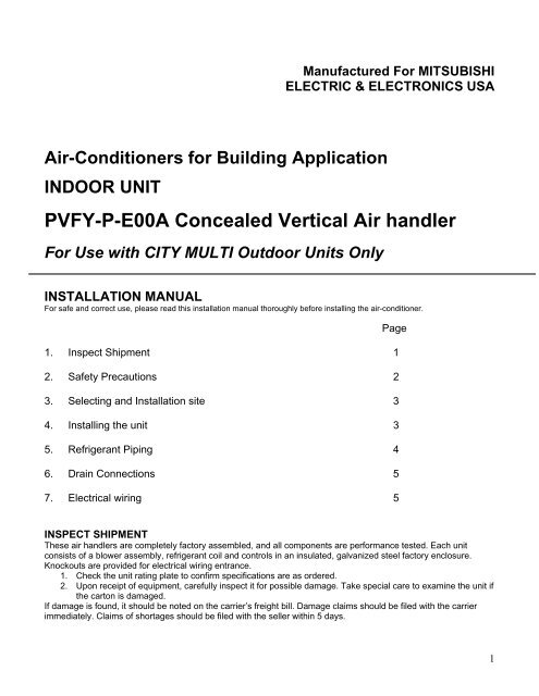
Air-Conditioners for Building Application<br />
INDOOR UNIT<br />
Manufactured For <strong>MITSUBISHI</strong><br />
<strong>ELECTRIC</strong> & ELECTRONICS USA<br />
<strong>PVFY</strong>-P-E00A Concealed Vertical Air handler<br />
For Use with CITY MULTI Outdoor Units Only<br />
<strong>INSTALLATION</strong> <strong>MANUAL</strong><br />
For safe and correct use, please read this installation manual thoroughly before installing the air-conditioner.<br />
1. Inspect Shipment 1<br />
2. Safety Precautions 2<br />
3. Selecting and Installation site 3<br />
4. Installing the unit 3<br />
5. Refrigerant Piping 4<br />
6. Drain Connections 5<br />
7. Electrical wiring 5<br />
Page<br />
INSPECT SHIPMENT<br />
These air handlers are completely factory assembled, and all components are performance tested. Each unit<br />
consists of a blower assembly, refrigerant coil and controls in an insulated, galvanized steel factory enclosure.<br />
Knockouts are provided for electrical wiring entrance.<br />
1. Check the unit rating plate to confirm specifications are as ordered.<br />
2. Upon receipt of equipment, carefully inspect it for possible damage. Take special care to examine the unit if<br />
the carton is damaged.<br />
If damage is found, it should be noted on the carrier’s freight bill. Damage claims should be filed with the carrier<br />
immediately. Claims of shortages should be filed with the seller within 5 days.<br />
1
Safety Precautions<br />
• Before installation and electric work<br />
Before installing the unit, make sure you read all the “Safety<br />
precautions”.<br />
The “Safety precautions” provide very important points regarding<br />
safety. Make sure you follow them.<br />
• Symbols used in the text<br />
Warning:<br />
Describes precautions that should be observed to prevent<br />
danger of injury or death to the user<br />
Caution:<br />
Describes precautions that should be observed to prevent<br />
damage to the unit<br />
Warning:<br />
Carefully read the labels affixed to the main unit.<br />
Warning:<br />
• The unit must be installed by an authorized Dealer or<br />
properly trained.<br />
− Improper installation by the user may result in water<br />
leakage, electric shock, or fire.<br />
• Install the air unit in a place that can withstand its<br />
weight.<br />
− Inadequate strength may cause the unit to fall down,<br />
resulting in injuries.<br />
• Use the specified cables for wiring. Make the<br />
connections securely so that the outside force of the<br />
cable is not applied to the terminals.<br />
− Inadequate connection and fastening may generate heat<br />
and cause a fire.<br />
• Prepare for typhoons, hurricanes, earthquakes etc. and<br />
install the unit at the specified place.<br />
− Improper installation may cause the unit to topple and result<br />
in injury.<br />
• Never repair the unit. If the air conditioner must be<br />
repaired, consult the dealer.<br />
− If the unit is repaired improperly, water leakage, electric<br />
shock, or fire may result.<br />
• Do no touch the heat exchanger fins.<br />
− Improper handling may result in injury.<br />
• When handling the product, always wear protective<br />
equipment.<br />
− EG: Gloves, full arm protection namely boiler suit, and<br />
safety glasses.<br />
− Improper handling may result in injury.<br />
• Install the air conditioner according to this Installation<br />
Manual.<br />
− If the unit is installed improperly, water leakage, electric<br />
shock, or fire may result.<br />
• Have all electric work done by a licensed electrician<br />
according the “Electric Facility Engineering Standard”<br />
and “Interior Wire Regulations” and the instructions<br />
given in this manual and always use a special circuit.<br />
− If the power source capacity is inadequate or electric work<br />
is performed improperly, electric shock and fire may result.<br />
• Keep the electric parts away from water (washing water<br />
etc.).<br />
− It might result in electric shock, catching fire or smoke.<br />
• When washing the Heat Exchanger and Drain Pan,<br />
ensure the Control Box, Motor and LEV remain dry,<br />
using a water proof covering.<br />
• When installing and moving the air conditioner to<br />
another site, do not charge it with a refrigerant<br />
different from the refrigerant specified on the unit.<br />
− If a different refrigerant or air is mixed with the original<br />
refrigerant, the refrigerant cycle may malfunction and the<br />
unit may be damaged.<br />
• When moving and reinstalling the air conditioner,<br />
consult the dealer or an authorized technician.<br />
− If the air conditioner is installed improperly, water<br />
leakage, electric shock, or fire may result.<br />
• Do not reconstruct or change the settings of the<br />
protections devices.<br />
− If the pressure switch, thermal switch, or other protection<br />
devices are shorted and operated forcibly, or parts other<br />
than those specified by Mitsubishi Electric are used, fire<br />
or explosion may result.<br />
• To dispose of this product, consult your dealer.<br />
• Do not use a leak detection additive.<br />
Precautions for devices that use R410A refrigerant<br />
Caution:<br />
• Do not use the existing refrigerant piping.<br />
− The old refrigerant and refrigeration oil in the existing<br />
piping contains a large amount of chlorine which may<br />
cause the refrigerator oil of the new unit to deteriorate.<br />
• Use refrigerant piping made of C1220 (Cu-DHP)<br />
phosphorus deoxidized copper as specified in the JIS<br />
H3300 “Copper and copper alloy seamless pipes and<br />
tubes”. In addition, be sure that the inner and outer<br />
surfaces of the pipes are clean and free of hazardous<br />
sulphur, oxides, dust/dirt, shaving particles, oils,<br />
moisture, or any other contaminants.<br />
− Contaminants on the inside of the refrigerant piping may<br />
cause the refrigerant residual oil to deteriorate<br />
• Store the piping to be used during installation indoors<br />
and keep both ends of the piping sealed until just<br />
before brazing. (Store elbows and other joints in a<br />
plastic bag.)<br />
− If dust, dirt, or water enters the refrigerant cycle,<br />
deterioration of the oil and compressor trouble may result.<br />
• Use liquid refrigerant to fill the system.<br />
− If gas refrigerant is used to seal the system, the<br />
composition of the refrigerant in the cylinder will change<br />
and performance may drop.<br />
• Do not use a refrigerant other than R410A.<br />
− If another refrigerant is used, the chlorine in the<br />
refrigerant may cause the refrigerator oil to deteriorate.<br />
• Use a vacuum pump with a reverse flow check valve.<br />
− The vacuum pump oil may flow back into the refrigerant<br />
cycle and cause the refrigerator oil to deteriorate.<br />
• Do not use the following tools that are used with<br />
conventional refrigerants.<br />
− (Gauge manifold, charge hose, gas leak detector,<br />
reverse flow check valve, refrigerant charge base,<br />
vacuum gauge, refrigerant recovery equipment).<br />
2
− If the conventional refrigerant and refrigeration oil are mixed<br />
in the R410A, the refrigerant may deteriorate.<br />
− If water is mixed in the R410A, the refrigeration oil may<br />
deteriorate.<br />
− Since R410A does not contain any chlorine, gas leak<br />
detectors for conventional refrigerant will not react to it.<br />
• Be especially careful when managing the tools.<br />
− If dust, dirt, or water gets in the refrigeration system, the<br />
refrigerant may deteriorate.<br />
Before Getting Started<br />
Caution:<br />
• Do not install the unit where combustible gas may leak.<br />
− If the gas leaks and accumulates around the unit, an<br />
explosion may result.<br />
• Do not use the air conditioner in special environments.<br />
− Oil, steam, sulfuric smoke, etc. can significantly reduce the<br />
performance of the air conditioner or damage its parts.<br />
• When installing the unit in a hospital, communication<br />
station, or similar place, provide sufficient protection<br />
against noise.<br />
− The inverter equipment, private power generator, highfrequency<br />
medical equipment, or radio communication<br />
equipment may cause the air conditioner to operate<br />
erroneously, or fail to operate. On the other hand, the air<br />
conditioner may affect such equipment by creating noise<br />
that disturbs medical treatment of image broadcasting.<br />
• Do not install the unit on a structure that may cause<br />
leakage.<br />
− When the room humidity exceeds 80% or when the drain<br />
pipe is clogged, condensation may drip from the indoor unit.<br />
Perform collective drainage work together with the outdoor<br />
unit, as required.<br />
Before getting installed (moved)-electrical work<br />
Caution:<br />
• Ground the unit.<br />
− Do not connect the ground wire to gas or water pipes,<br />
lightning rods, or telephone ground lines. Improper<br />
grounding may result in electric shock.<br />
• Install the power cable so that tension is not applied to<br />
the cable.<br />
− Tension may cause the cable to break and generate heat<br />
and cause a fire.<br />
• Use power line cables of sufficient current carrying<br />
capacity and rating.<br />
− Cables that are too small may leak, generate heat, and<br />
cause a fire.<br />
• Use only a circuit breaker and fuse of the specified<br />
capacity.<br />
− A fuse or circuit breaker of a larger capacity or a steel or<br />
copper wire may result in a general unit failure or fire.<br />
• Do not wash the air conditioner units.<br />
− Washing them may cause an electric shock.<br />
• Be careful that the installation base is not damaged by<br />
long use.<br />
− If the damage is left uncorrected, the unit may fall and<br />
cause personal injury or property damage.<br />
• Install the drain piping according to this Installation<br />
Manual to ensure proper drainage. Wrap thermal<br />
insulation around the pipes to prevent condensation.<br />
− Improper drain piping may cause water leakage and<br />
damage to furniture and other possessions.<br />
• Be very careful about product transportation<br />
− If the product weighs more than 20 kg [44 lb], then more<br />
than one person should carry the product.<br />
− Some products use PP bands for packaging. Do not use<br />
any PP bands for a means of transportation; it is<br />
dangerous.<br />
− Do not touch the heat exchanger fins. Doing so may cut<br />
your fingers.<br />
• Safely dispose of the packing materials.<br />
− Packing materials, such as nails and other metal or<br />
wooden parts, may cause stabs or other injuries.<br />
− Tear apart and throw away plastic packaging bags so<br />
that children will not play with them. If children play with a<br />
plastic bag which was not torn apart, they face the risk of<br />
suffocation.<br />
Before Starting the test run<br />
Caution:<br />
• Turn on the power at least 12 hours before starting<br />
operation.<br />
− Starting operation immediately after turning on the main<br />
power switch can result in severe damage to internal<br />
parts. Keep the power switch turned on during the<br />
operational season.<br />
• Do not touch the switches with wet fingers.<br />
− Touching a switch with wet fingers can cause electric<br />
shock.<br />
• Do not touch the refrigerant pipes during and<br />
immediately after operation.<br />
− During and immediately after operation, the refrigerant<br />
pipes may be hot or may be cold, depending on the<br />
condition of the refrigerant flowing through the refrigerant<br />
piping, compressor, and other refrigerant cycle parts.<br />
Your hands may suffer burns or frostbite if you touch the<br />
refrigerant pipes.<br />
• Do not operate the air conditioner with the panels and<br />
guards removed.<br />
− Rotating, hot, or high-voltage parts can cause injuries.<br />
• Do not turn off the power immediately after stopping<br />
operation.<br />
− Always wait at least five minutes before turning off the<br />
power. Otherwise, water leakage and trouble may occur.<br />
SELECTING AN <strong>INSTALLATION</strong> SITE<br />
• Avoid locations exposed to outside air.<br />
• Select a location free of obstructions to the airflow in and out<br />
of the unit.<br />
• Avoid locations exposed to steam or vapor<br />
• Avoid locations where combustible gas may leak, settle or be<br />
generated.<br />
• Avoid installation near machines emitting high-frequency<br />
waves (high frequency welders, etc.).<br />
• Avoid locations where the airflow is directed at a fire alarm<br />
sensor. (Hot air could trigger the alarm during operation)<br />
• Avoid places where acidic solutions are frequently used.<br />
• Avoid places where sulphur-based or other sprays are<br />
commonly used.<br />
• If the unit is run for long hours when the air surrounding the<br />
unit is a high temperature/high humidity (dew point above<br />
80 o F, dew condensation may be produced on the unit. When<br />
operating the units in this condition, add insulation material<br />
(13/32 – 13/16 in) to the entire surface of the unit to avoid<br />
condensation.<br />
3
INSTALLING THE UNIT<br />
The air handler can be installed in a vertical or horizontal (left only)<br />
configuration as shown below. The units are designed for “0” zero<br />
clearance to combustibles. 24” is required for service access to the<br />
front of the unit. (See below) Regardless of mounting configuration,<br />
the air handler must be mounted level to facilitate proper condensate<br />
drainage.<br />
Installation Clearances<br />
TOP View<br />
Vertical Installation<br />
Clearance Area<br />
Width of Unit<br />
24"<br />
TOP View<br />
Horizontal Installation<br />
Clearance Area<br />
Length of Unit<br />
Vertical Applications: The air handler must be supported on the<br />
bottom only and set on a solid floor with a return plenum below or<br />
field supplied supporting frame or plenum. Securely attach the air<br />
handler to the floor or supporting frame or plenum.<br />
Unit Mounted on Return Plenum<br />
Horizontal (LEFT ONLY) Installations: No changes need to<br />
be made to the unit for horizontal installation. The unit can be<br />
installed on a platform or suspended from rails as shown below. The<br />
rails must run the length of the unit and be of sufficient strength to<br />
support the weight of the unit and connected ductwork. Vibration<br />
isolation is recommended for horizontal installations. Some<br />
jurisdictions may require an auxiliary drain pan be mounted under the<br />
unit. Always follow local or national code requirements.<br />
Platform Mounting<br />
Suspended Mounting<br />
24"<br />
_____________________________________<br />
Air Filter<br />
An air filter (provided by others) is to be installed on the return side<br />
of the air handler. The face area and pressure drop is to be<br />
determined by the installing contractor based on the overall static<br />
pressure performance of the system including supply and return<br />
ductwork sizing. The factory static pressure performance is .30”<br />
esp. A field selectable .50 esp. is available. See instructions for<br />
changing to .50 esp in the electrical section.<br />
REFRIGERANT PIPING<br />
This piping work must be done in accordance with the installation<br />
manuals for both outdoor unit and BC controller (R2/WR2 series)<br />
Series R2 is designed to operate in a system that the refrigerant<br />
pipe from an outdoor unit is received by the BC controller and<br />
branches at the BC controller to the indoor units.<br />
For constraints on piping length and allowable difference of<br />
elevation, refer to the design section of the engineering manual.<br />
The method of pipe connection on the air handler is braze<br />
connection.<br />
Cautions of refrigerant piping<br />
Be sure to use non-oxidative procedures for<br />
brazing to ensure that no foreign matter or<br />
moisture enters the piping.<br />
ALWAYS USE A NITROGEN PURGE IN THE PIPING<br />
DURING BRAZING<br />
Provide proper bracing for refrigerant piping so no load is<br />
imparted upon the connections at the air handler.<br />
Warning:<br />
When installing and moving the unit, do not charge it with<br />
refrigerant other than the refrigerant specified on the unit.<br />
Mixing of a different refrigerant, air, etc. may cause the<br />
refrigerant cycle to malfunction and result in severe<br />
damage.<br />
Caution:<br />
Use refrigerant piping made of C1220 (Cu-DHP)<br />
phosphorous deoxidized copper as specified in ASTM<br />
B280 Standard for copper and copper alloy seamless<br />
pipes and tubes. In addition, be sure that the inner and<br />
outer surfaces of the pipes are clean and free of<br />
hazardous sulphur, oxides, dust/dirt, shaving particles,<br />
oils, moisture, or any other contaminant.<br />
Never use existing refrigerant piping.<br />
Caution: COIL UNDER PRESSURE<br />
Always wear safety glasses when working around<br />
pressurized devices.<br />
4
The air handlers are shipped with a nitrogen holding charge<br />
in the coil. Carefully follow these instructions when<br />
releasing the charge.<br />
The suction line stub contains a schrader valve where the factory<br />
pre-charged the coil with nitrogen. This valve is located behind the<br />
panel that the suction line comes out. This can be accessed by<br />
removing the blower panel (top panel). (See drawing below)<br />
Remove the cap and depress the schrader valve core to release all<br />
pressure within the coil. Replace the cap and finger tighten. Once all<br />
pressure is released the brazed ends of both tubes can now be<br />
removed with a tubing cutter. If necessary ream the connections to<br />
accept the refrigerant lines.<br />
Front panel<br />
Vapor Connection<br />
Cut here after<br />
relieving pressure<br />
Schrader valve<br />
Always use proper refrigerant line sizes as shown:<br />
Unit size<br />
P12, P18 1/4” liquid x 1/2” gas<br />
P24 – P54 3/8” liquid x 5/8” gas<br />
Both refrigerant lines need to be insulated all the way up to the<br />
cabinet. Make sure the openings in the cabinet around the refrigerant<br />
lines are sealed. 3/8 in thick insulation is the minimum recommended<br />
thickness. Based on ambient conditions and line length, thicker<br />
insulation may be desired.<br />
Drain Connections<br />
IMPORTANT!<br />
Over-tightening the drain connections could result in drain pan<br />
breakage and failure.<br />
The air handler contains three sets of ¾” FPT drain connections.<br />
When the unit is used in the vertical position, there are a left-hand set<br />
and a right-hand set. When the unit is mounted horizontal (left only)<br />
there is one set. Each set contains a primary drain and a secondary<br />
or auxiliary drain. The primary drain is the one that is lowest (even<br />
with the bottom of the pan). The secondary drain is at the higher level.<br />
These units operate with a negative pressure at the drain<br />
connections and require a drain trap be installed to prevent air from<br />
being drawn in and preventing positive drainage.<br />
The trap needs to be installed as close to the unit as possible. Make<br />
sure the top of the trap is below the connection to the drain pan to<br />
allow complete drainage of the pan.<br />
2" Min.<br />
2" Min.<br />
2" Min.<br />
Vent T<br />
Drain Trap<br />
Anti-syphon<br />
air vent<br />
Note: Horizontal runs must also have an anti-siphon air vent<br />
(standpipe) install ahead of the horizontal run to eliminate air<br />
trapping. Horizontal drain lines must be pitched a minimum 1/8”<br />
per foot.<br />
Route the drain lines outside or to an appropriate drain. Drain lines<br />
must be installed so they do not block service access to the front<br />
of the unit. 24” clearance in the front is for routine maintenance or<br />
service.<br />
Note: Check local codes before connecting the drain line to an<br />
existing drainage system.<br />
Insulate the drain lines where sweating could cause water damage.<br />
Upon completion of installation, it is the responsibility of the<br />
installer to ensure the drain pan(s) is capturing all condensate, and<br />
all condensate is draining properly and not getting into the<br />
ductwork/system.<br />
Vertical Mounting:<br />
When mounted vertically, the air handler has a choice of left or<br />
right hand drain connections. Select the drain connection set that<br />
is most convenient for routing piping.<br />
For left hand drains the connections are visible and ready for<br />
installation. Attach the drain connectors finger tight and install the<br />
drain line. For right hand remove the caps covering the drain pan<br />
openings. Remove the plugs and reinstall in the left hand drain<br />
opening. Install cover caps over these plugs. Now attach the drain<br />
connector finger tight and install the drain line.<br />
IMPORTANT!<br />
Over-tightening the drain connection could result in drain pan<br />
breakage and failure.<br />
The secondary connection if used should be connected to a<br />
separate drainage system. Run the secondary drain so the<br />
occupants will be able to notice water flowing through the<br />
secondary drain indicating a blockage in the primary drain.<br />
Optional use for the secondary is a primary drain line overflow<br />
switch (provided by others). This device will shut the cooling<br />
operation unit down in the event of a primary drain line blockage.<br />
See wiring section for connecting this device.<br />
Horizontal:<br />
If the unit is installed horizontally, remove the plugs installed in the<br />
drain pan openings and attach connector finger tight and route<br />
drain line. Any vertical drain pan openings must be covered to<br />
eliminate air loss.<br />
IMPORTANT!<br />
Over-tightening the drain connection could result in drain pan<br />
breakage and failure.<br />
The secondary connection if used should be connected to a<br />
separate drainage system. Run the secondary drain so the<br />
occupants will be able to notice water flowing through the<br />
secondary drain indicating a blockage in the primary drain.<br />
Optional use for the secondary is a primary drain line overflow<br />
switch (provided by others). This device will shut the cooling<br />
operation unit down in the event of a primary drain line blockage.<br />
See wiring section for connecting this device.<br />
5
<strong>ELECTRIC</strong>AL WIRING<br />
Warning:<br />
Electrical work should be done by a qualified electrical<br />
contractor in accordance with “Engineering Standards for<br />
Electrical Installation” and supplied installation manuals. If<br />
the power circuit lacks capacity or has an installation failure,<br />
it may cause a risk of electrical shock or fire.<br />
− Be sure to follow local and national code requirements<br />
when wiring these units<br />
− Install the unit to prevent that any of the control circuit<br />
cables (remote controller, transmission cables) is brought in<br />
direct contact with the power cable outside the unit.<br />
− Ensure that there is no tension on any wire connections<br />
Caution:<br />
Be sure to ground the unit. Do not connect the grounding<br />
cable to any gas pipe, water pipe, lightening rod, or<br />
telephone earth cable. Incomplete grounding may cause a<br />
risk of electrical shock.<br />
Types of control cables<br />
Wiring transmission cables (M-NET)<br />
Types of transmission cable: Shielded wire CVVS or CPEVS<br />
Cable diameter: (AWG16)<br />
Maximum wiring length: Within 200 m (656ft.)<br />
Maximum length of transmission lines for centralized control and<br />
indoor/outdoor lines (Maximum length via indoor units): 500 m<br />
[1640ft] MAX<br />
The maximum length of the wiring between power supply (PAC-<br />
SC51KUA) for transmission lines (on the transmission lines for<br />
centralized control) and each outdoor unit and system controller is<br />
200 m (656ft)<br />
Controllers<br />
M-NET (ME) Controllers<br />
Type of transmission cable: Sheathed 2-core cable (unshielded)<br />
Cable diameter: (AWG18)<br />
Note: When 10 m (33 ft) is exceeded use same cable as<br />
specified for transmission wiring above.<br />
MA Controllers – Minimum 18 gauge<br />
Type of transmission cable: Sheathed 2-core cable (unshielded)<br />
Cable diameter: (AWG18)<br />
Note: Length not to exceed 200 m (265’)<br />
Power Supply wiring<br />
Power supply cords of appliances shall not be lighter than design 245<br />
IEC 57 or 227 IEC 57.<br />
Wire size for Main Power Supply and On/Off<br />
Capacities.<br />
Minimum Wire size AWG<br />
Main Cable: 14<br />
Branch: 14<br />
Ground: 14<br />
Breaker for Wiring (NFB)<br />
15 A<br />
Caution:<br />
Fan<br />
Speed<br />
Relays<br />
Do not use anything other than the correct capacity breaker<br />
and fuse. Using fuse, wire or copper wire with too large<br />
capacity may cause a risk of malfunction or fire.<br />
Electrical Box Component Location<br />
Low<br />
Med<br />
High<br />
L1 G L2 1 2<br />
M1 M2 S<br />
Circuit Board<br />
12V DC 12V AC<br />
Line Voltage<br />
TB15 TB5<br />
Terminal Strip<br />
208/230V 1ph.<br />
Terminal Terminal Transformers<br />
Connecting remote controller, indoor and outdoor<br />
transmission cables<br />
Connect indoor unit TB5 and outdoor unit TB3. (Non-polarized 2wire)<br />
The “S” on indoor unit TB5 is a shielding wire connection. For<br />
specifications about the connecting cables, refer to the outdoor<br />
unit installation manual.<br />
Install a remote controller following the manual supplied with the<br />
remote controller.<br />
Connect the “1” and “2” on the indoor unit TB15 to a MA remote<br />
controller. (Non-polarized 2-wire)<br />
Connect the “M1” and “M2” on indoor unit TB5 to an M-NET<br />
remote controller. (Non-polarized 2-wire)<br />
Typical transmission wire connections<br />
when using MA remote controllers<br />
Outdoor<br />
Indoor<br />
Indoor<br />
Unit<br />
Unit<br />
Unit<br />
TB3 TB5 TB15<br />
TB5 TB15<br />
M1 M2 M1 M2 S 1 2 M1 M2 S 1 2<br />
MA<br />
Controller<br />
MA<br />
Controller<br />
The MA remote controller and the M-NET remote controller cannot<br />
be used at the same time or interchangeably.<br />
6
Typical transmission wire connections<br />
when using ME remote controllers<br />
Outdoor Indoor Indoor<br />
Unit<br />
Unit Unit<br />
TB3 TB5 TB5<br />
M1 M2 M1 M2 S M1 M2 S<br />
ME<br />
Controller<br />
ME<br />
Controller<br />
Note:<br />
Ensure that the wiring is not pinched when fitting the terminal box<br />
cover. Pinching the wiring may cut it.<br />
Caution:<br />
Install wiring so that it is not tight and under tension. Wiring under<br />
tension may break or overheat and burn.<br />
Fix power source wiring to control box by using buffer bushing or<br />
tensile force. (PG connection or the like.) Connect transmission<br />
wiring to transmission terminal block through the knockout hole of<br />
control box using ordinary bushing.<br />
After wiring is complete, make sure again that there is no tension on<br />
the connections, and attach the cover onto the control box in the<br />
reverse order removal.<br />
Caution:<br />
Wire the power supply so that no tension is imparted. Otherwise<br />
disconnection, heating or fire may result.<br />
Important:<br />
Attach shielding ground on the outdoor unit’s ground terminal.<br />
If the remote controller cable exceeds 10 m [32 ft], use a 1.25 mm 2<br />
[AWG16] diameter cable over the exceeded portion, and add that<br />
exceeded position to within 200 m [656 ft].<br />
The BC controller is required only for simultaneous cooling and<br />
heating series R2.<br />
Connecting Line Voltage<br />
Make sure power supply is off.<br />
On the line voltage terminal block loosen the screws marked L1, L2<br />
and G on the line voltage terminal strip. Insert line voltage wires and<br />
tighten screws.<br />
L1 G L2<br />
Caution:<br />
Wire the power supply so that no tension is imparted. Otherwise<br />
disconnection, heating, or fire may result.<br />
208 Volt Power Supply<br />
The air handler comes from the factory with the 24VAC<br />
transformer wired for a 230 volt supply voltage. For 208 volt power<br />
supply the line voltage lead needs to be changed.<br />
Remove the wire nut covering the orange wire. Disconnect the<br />
black wire from the black lead going to the line voltage terminal<br />
strip. Connect the orange lead to the black wire going to the line<br />
voltage terminal strip using the wire nut. Now cover the black lead<br />
with the remaining wire nut (see below)<br />
For 208V power supply,<br />
switch the transformer lead<br />
marked 230V with the one<br />
marker 208V. Reattach<br />
wire nut to bare wire.<br />
208 V Orange<br />
230 V Black<br />
L2 White<br />
Setting addresses<br />
(Be sure to operate with the main power turned OFF.)<br />
<br />
Lower right corner<br />
of circuit board<br />
SW14 SW12 SW11<br />
208/230VAC<br />
There are two types of rotary switch setting available: setting<br />
addresses 1 to 9 and over 10, and setting branch numbers.<br />
How to set addresses:<br />
Example: If Address is “3”, leave SW12 (for over 10) at “0”,<br />
and match SW11 (for 1 to 9) with “3”<br />
How to set branch numbers SW14 (Series R2 only):<br />
Match the indoor unit’s refrigerant pipe with the BC<br />
controller’s end connection number. If there is no BC<br />
controller used leave at “0”.<br />
The rotary switches are all set to “0” when shipped from the factory.<br />
These switches can be used to set unit addresses and branch<br />
numbers at will.<br />
The determination of indoor unit addresses varies with the system<br />
at site. Set them referring to technical date.<br />
_____________________________________<br />
Sensing room temperature with the built-in sensor in<br />
a remote controller<br />
T<br />
7
If you want to sense room temperature with the built-in sensor in a<br />
remote controller, set SW1-1 on the control board to “ON”. The<br />
setting of SW1-7 and SW1-8 as necessary also makes it possible to<br />
adjust the air flow at a time when the heating thermometer is off.<br />
_______________________________________<br />
Condensate overflow safety switch connection (CN31)<br />
The circuit board is equipped with a connection to attach a<br />
condensate safety float switch. The switch should be a normally<br />
closed low voltage rated switch. The switch should be installed in a<br />
location that it can sense a drain blockage causing a rise in water<br />
level. This resulting rise in level will cause it to open. The switch<br />
location is to be determined by the installing contractor. When the<br />
switch opens, it will cause the LEV to close, stopping the cooling<br />
operation. The fan will continue to run and a fault code will be shown<br />
at the controller. Correcting the problem and closing the switch will<br />
be required before normal operation can resume.<br />
See installation below:<br />
Locate the CN31 connector in the upper right-hand corner of the<br />
circuit board. Carefully remove the connector with the jumper from<br />
the board. Cut the jumper on the CN31 connector and wire a<br />
normally closed safety float switch across these wires.<br />
Carefully reinstall the connector back onto the board<br />
CN31<br />
Upper right corner<br />
of circuit board<br />
Normally Closed<br />
Float switch<br />
______________________________________________<br />
Changing Blower Static Pressure<br />
The air handler is equipped with an adjustable static pressure setting.<br />
The factory setting is 0.30” esp. An optional 0.50 esp. setting is<br />
available by moving three wires on the motor.<br />
Use pliers to grasp and remove the connectors. Failure to do so<br />
could result in the wire pulling free from the spade connectors.<br />
Step 1<br />
Remove wire on connector 2 and reinstall on connector 1<br />
Step 2<br />
Remove wire on connector 3 and reinstall on connector 2<br />
Step 3<br />
Remove wire on connector 4 and reinstall on connector 3<br />
As shipped<br />
.30 esp connection<br />
FAN MOTOR<br />
24 VAC Common<br />
1 C<br />
24 VAC<br />
2 L<br />
24 VAC 208/230V 60Hz<br />
3 G<br />
24 VAC 208/230V 60Hz<br />
4 N<br />
5<br />
For field selected .50 esp, change low<br />
voltage connections as shown<br />
FAN MOTOR<br />
24 VAC<br />
1 C<br />
24 VAC<br />
2 L<br />
24 VAC<br />
3 G<br />
4<br />
5<br />
N<br />
8