FCX PPC
FCX PPC
FCX PPC

Create successful ePaper yourself
Turn your PDF publications into a flip-book with our unique Google optimized e-Paper software.
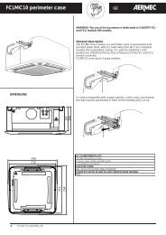
Ventilconvettore per installazione canalizzata con depuratore PLASMACLUSTER®<br />
Fancoil for duct installation with PLASMACLUSTER® purifier<br />
Ventilo-convecteur installation pour canalisation avec dépurateur PLASMACLUSTER®<br />
Gebläsekonvektor Truhenmodelle mit Reinigungsapparat PLASMACLUSTER®<br />
Fan coil para instalaciones por conducto con depurador PLASMACLUSTER®<br />
<strong>FCX</strong> <strong>PPC</strong><br />
ISO 9001 - Cert. n° 0128/4<br />
MANUALE D’USO E INSTALLAZIONE<br />
USE AND INSTALLATION MANUAL<br />
MANUEL D'UTILISATION ET D'INSTALLATION<br />
BEDIENUNGS- UND INSTALLATIONSANLEITUNG<br />
MANUAL DE INSTRUCCIONES E INSTALACIÓN<br />
I<strong>FCX</strong><strong>PPC</strong>LJ<br />
0711<br />
64560.58_02<br />
Sostituisce il Replace Remplace le n° Ersetzt Sustituye a: 64560.58_01 / 0703
Italiano<br />
English<br />
Español Deutsche<br />
Français<br />
INDICE<br />
DICHIARAZIONE DI CONFORMITÀ<br />
Trasporto Simboli di sicurezza<br />
Dati dimensionali<br />
Disegni<br />
Schema elettrico<br />
Plasmacluster Imballo Installazione dell’unità Collegamenti elettrici Rotazione batteria<br />
Informazioni importanti e manutenzione<br />
SOLUZIONE DEI PROBLEMI<br />
SERVIZIO ASSISTENZA TECNICA IN ITALIA<br />
INDEX<br />
DECLARATION OF CONFORMITY<br />
Carriage Safety symbol<br />
Dimensions<br />
Sketches<br />
Wiring diagram<br />
Plasmacluster Packaging Unit installation Electrical connections Battery rotation<br />
Important information and maintenance<br />
TROUBLE SHOOTING<br />
INDEX<br />
CERTIFICAT DE CONFORMITE<br />
Transport Simboles de securite<br />
Dimensions<br />
Dessin<br />
Schemas electriques<br />
Plasmacluster Emballage Installation de l'unité Raccordements électriques Rotation batterie<br />
Informations importantes et entretien<br />
SOLUTION DES PROBLEMES<br />
INDEX<br />
KONFORMITÄTSERKLÄRUNG<br />
Transport Sicherheitssymbole<br />
Abmessungen<br />
Designs<br />
Schaltpläne<br />
Plasmacluster Verpackung Installation der Einheit Elektrische Anschlüsse Umdrehen des Wärmetauschers<br />
Wichtige Informationen und Wartung<br />
PROBLEMLÖSUNG<br />
ÍNDICE<br />
DECLARACIÓN DE CONFORMIDAD<br />
Transporte Símbolos de seguridad<br />
Dimensiones<br />
Diseños<br />
Esquemas eléctricos<br />
Plasmacluster Embalaje Instalación de la unidad Conexiones eléctricas Giro batería<br />
Información importante y mantenimiento<br />
SOLUCIÓN DE PROBLEMAS<br />
3<br />
4<br />
5<br />
8<br />
10<br />
12<br />
13<br />
22<br />
23<br />
3<br />
4<br />
5<br />
8<br />
10<br />
14<br />
15<br />
22<br />
3<br />
4<br />
5<br />
8<br />
10<br />
16<br />
17<br />
22<br />
3<br />
4<br />
5<br />
8<br />
10<br />
18<br />
19<br />
22<br />
3<br />
4<br />
5<br />
8<br />
10<br />
20<br />
21<br />
22
AERMEC S.p.A.<br />
I-37040 Bevilacqua (VR) Italia – Via Roma, 44<br />
Tel. (+39) 0442 633111<br />
Telefax (+39) 0442 93730 – (+39) 0442 93566<br />
www.aermec.com - info@aermec.com<br />
DICHIARAZIONE DI CONFORMITÀ<br />
Noi, fi rmatari della presente, dichiariamo sotto la nostra esclusiva<br />
responsabilità, che il prodotto:<br />
VENTILCONVETTORE<br />
serie <strong>FCX</strong> <strong>PPC</strong><br />
al quale questa dichiarazione si riferisce è conforme alle seguenti norme<br />
armonizzate:<br />
- CEI EN 60335-2-40<br />
- CEI EN 55014-1<br />
- CEI EN 55014-2<br />
- CEI EN 61000-6-1<br />
- CEI EN 61000-6-3<br />
soddisfando così i requisiti essenziali delle seguenti direttive:<br />
- Direttiva LVD 2006/95/CE<br />
- Direttiva compatibilità elettromagnetica 2004/108/CE<br />
- Direttiva Macchine 98/37/CE<br />
<strong>FCX</strong> <strong>PPC</strong> CON ACCESSORI<br />
E’ fatto divieto di mettere in servizio il prodotto dotato di accessori<br />
non di fornitura Aermec.<br />
CERTIFICAT DE CONFORMITÉ<br />
Nous soussignés déclarons sous notre exclusive responsabilité que le<br />
produit:<br />
VENTILO-CONVECTEURS<br />
série <strong>FCX</strong> <strong>PPC</strong><br />
auquel cette déclaration fait référence, est conforme aux normes<br />
harmonisées suivantes:<br />
- EN 60335-2-40<br />
- EN 55014-1<br />
- EN 55014-2<br />
- EN 61000-6-1<br />
- EN 61000-6-3<br />
satisfaisant ainsi aux conditions essentielles des directives suivantes:<br />
- Directive LVD 2006/95/CE<br />
- Directive compatibilité électromagnétique 2004/108/CE<br />
- Directive Machines 98/37/CE<br />
<strong>FCX</strong> <strong>PPC</strong> PLUS ACCESSOIRES<br />
Il est interdit de faire fonctionner l'appareil avec des accessoires qui<br />
ne sont pas fournis de Aermec.<br />
DECLARACIÓN DE CONFORMIDAD<br />
Los que suscriben la presente declaran bajo la propia y exclusiva<br />
responsabilidad que el conjunto en objeto, defi nido como sigue:<br />
FAN COIL<br />
serie <strong>FCX</strong> <strong>PPC</strong><br />
al que esta declaración se refi ere, está en conformidad a las siguientes<br />
normas armonizadas:<br />
- EN 60335-2-40<br />
- EN 55014-1<br />
- EN 55014-2<br />
- EN 61000-6-1<br />
- EN 61000-6-3<br />
al que esta declaración se refi ere, está en conformidad a las siguientes<br />
normas armonizadas:<br />
- Directiva LVD 2006/95/CE<br />
- Directiva compatibilidad electromagnétic 2004/108/CE<br />
- Directiva máquinas 98/37/CE<br />
<strong>FCX</strong> <strong>PPC</strong> CON ACCESORIOS<br />
Está prohibido poner en marcha el producto con accesorios<br />
no suministrados por Aermec.<br />
<strong>FCX</strong> <strong>PPC</strong><br />
CONFORMITY DECLARATION<br />
We the undersigned declare, under our own exclusive responsibility,<br />
that the product:<br />
FAN COIL<br />
<strong>FCX</strong> <strong>PPC</strong> series<br />
to which this declaration refers, complies with the following standardised<br />
regulations:<br />
- EN 60335-2-40<br />
- EN 55014-1<br />
- EN 55014-2<br />
- EN 61000-6-1<br />
- EN 61000-6-3<br />
thus meeting the essential requisites of the following directives:<br />
- Directive LVD 2006/95/CE<br />
- EMC Electromagnetic Compatibility Directive 2004/108/CE<br />
- Machine Directive 98/37/CE<br />
<strong>FCX</strong> <strong>PPC</strong> WITH ACCESSORIES<br />
It is not allowed to use the unit equipped with accessories not supplied<br />
by Aermec.<br />
KONFORMITÄTSERKLÄRUNG<br />
Wir, die hier Unterzeichnenden, erklären auf unsere ausschließlich<br />
Verantwortung, dass das Produkt:<br />
GEBLÄSEKONVEKTOR<br />
der Serie <strong>FCX</strong> <strong>PPC</strong><br />
auf das sich diese Erklärung bezieht, den folgenden harmonisierten Normen<br />
entspricht:<br />
- EN 60335-2-40<br />
- EN 55014-1<br />
- EN 55014-2<br />
- EN 61000-6-1<br />
- EN 61000-6-3<br />
womit die grundlegenden Anforderungen folgender Richtlinien erfüllt<br />
werden:<br />
- Richtlinie LVD 2006/95/CE<br />
- Richtlinie zur elektromagnetischen Verträglichkeit 2004/108/CE<br />
- Maschinenrichtlinie 98/37/CE<br />
<strong>FCX</strong> <strong>PPC</strong> + ZUBEHÖR<br />
Falls das Gerät mit Zubehörteilen ausgerüstet wird, die nicht von<br />
Aermec geliefert werden, ist dessen Inbetriebnahme solange untersagt.<br />
Bevilacqua, 01/10/2007 La Direzione Commerciale – Sales and Marketing Director<br />
Luigi Zucchi
Italiano<br />
English<br />
Español Deutsche<br />
Français<br />
TRASPORTO CARRIAGE TRANSPORT TRANSPORT TRANSPORTE<br />
4<br />
NON bagnare Do NOT wet<br />
CRAINT l’humidité Vor Nässe schützen<br />
NO mojar<br />
Sovrapponibilità: controllare sull’imballo la posizione della freccia per<br />
conoscere il numero di macchine impilabili.<br />
Stacking: control the packing for the arrow position to know the number<br />
of machines that can be stacked.<br />
Empilement: vérifier sur l’emballage la position de la flèche pour connaître<br />
le nombre d’appareils pouvant être empilés.<br />
Stapelung: Anhand der Position des Pfeiles an der Verpackung kontrollieren,<br />
wieviele Geräte stapelbar sind.<br />
Apilamiento: observe en el embalaje la posición de la flecha para saber<br />
cuántos equipos pueden apilarse.<br />
NON trasportare la macchina da soli se il suo peso supera i 35 Kg.<br />
DO NOT handle the machine alone if its weight is over 35 Kg.<br />
NE PAS transporter tout seul l’appareil si son poids dépasse 35 Kg.<br />
Das Gerät NICHT alleine tragen, wenn sein Gewicht 35 Kg überschreitet.<br />
NO maneje los equipos en solitario si pesan más de 35 kg.<br />
SIMBOLI DI SICUREZZA SAFETY SYMBOL SIMBOLES DE SECURITE<br />
SICHERHEITSSYMBOLE SÍMBOLOS DE SEGURIDAD<br />
NON calpestare Do NOT trample<br />
NE PAS marcher sur cet emballage Nicht betreten<br />
NO pisar<br />
6<br />
5<br />
4<br />
3<br />
2<br />
1<br />
NON lasciare gli imballi sciolti durante il trasporto.<br />
Do NOT leave loose packages during transport.<br />
ATTACHER les emballages pendant le transport.<br />
Die Verpackungen nicht ungesichert transportieren.<br />
NO lleve las cajas sueltas durante el transporte.<br />
35Kg<br />
Pericolo: Pericolo: Pericolo!!!<br />
Tensione Organi in movimento<br />
Danger: Danger: Danger!!!<br />
Power supply Movings parts<br />
Danger: Danger: Danger!!!<br />
Tension Organes en mouvement<br />
Gefahr ! Gefahr ! Gefahr!!!<br />
Spannung Rotierende Teile<br />
Peligro: Peligro: Peligro!!!<br />
Tensión Elementos en movimiento
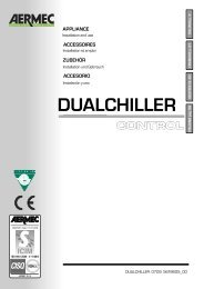
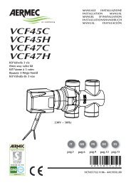
DATI DIMENSIONALI DIMENSIONS DIMENSIONS ABMESSUNGEN DIMENSIONES [mm]<br />
<strong>FCX</strong> 22 - 32 - 42 - 50 <strong>PPC</strong><br />
9 x 20<br />
197<br />
248<br />
25<br />
388<br />
Øe 17,5<br />
9 x 20<br />
110<br />
350<br />
Øe 17,5<br />
50<br />
<strong>FCX</strong> 62 - 82 <strong>PPC</strong><br />
A<br />
B<br />
30 30<br />
C 50<br />
A (<strong>FCX</strong>-P)<br />
C<br />
B<br />
14 14<br />
216<br />
41 101<br />
216<br />
41 107<br />
Mod. <strong>FCX</strong> 22 <strong>FCX</strong> 32 <strong>FCX</strong> 42 <strong>FCX</strong> 50 <strong>FCX</strong> 62 <strong>FCX</strong> 82<br />
A 562 793 1013 1013 1147 1147<br />
B 522 753 973 973 1122 1122<br />
C<br />
Peso<br />
Weight<br />
440 671 891 891 1102 1102<br />
Poids<br />
Gewicht<br />
Peso<br />
kg 13 18 22 22 33 33<br />
Attacchi batteria (femmina) Coil connection (female)<br />
Raccords batterie (femelle) Anschlüsse des Warmetäuschers (Innengewinde)<br />
Conexiones de la batería (hembra)<br />
Mod. <strong>FCX</strong> 22 <strong>FCX</strong> 32 <strong>FCX</strong> 42 <strong>FCX</strong> 50 <strong>FCX</strong> 62 <strong>FCX</strong> 82<br />
3 R 1/2” 1/2” 3/4” 3/4” 3/4” 3/4”<br />
49<br />
144<br />
453<br />
32<br />
253<br />
558<br />
216<br />
96 60<br />
216<br />
96 60<br />
45<br />
85<br />
39<br />
141<br />
5<br />
453<br />
558<br />
Italiano<br />
English<br />
Español Deutsche<br />
Français
Italiano<br />
English<br />
Español Deutsche<br />
Français<br />
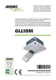
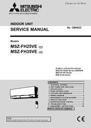
DATI DIMENSIONALI DIMENSIONS DIMENSIONS ABMESSUNGEN DIMENSIONES [mm]<br />
6<br />
<strong>FCX</strong> 22 - 32 - 42 - 50 <strong>PPC</strong><br />
100<br />
min.<br />
Installazione con supporti AMP (accessori) Installation with AMP brackets (accessories)<br />
Installation avec supports AMP (accessories) Installation mit AMP halterung (zubehöre)<br />
Instalación con soportes AMP (accesorios)<br />
36 258 105 258<br />
100<br />
min.<br />
5 5<br />
<strong>FCX</strong> <strong>PPC</strong><br />
A<br />
D C<br />
E<br />
F<br />
B<br />
<strong>FCX</strong> 62 - 82 <strong>PPC</strong><br />
G<br />
24x9<br />
Mod. <strong>FCX</strong> 22 <strong>FCX</strong> 32 <strong>FCX</strong> 42 <strong>FCX</strong> 50 <strong>FCX</strong> 62 <strong>FCX</strong> 82 <strong>PPC</strong><br />
A 750 981 1201 1201 1322 1322<br />
B 555 786 1006 1006 1127 1127<br />
C 600 831 1051 1051 1172 1172<br />
D 95,5 95,5 95,5 95,5 95,5 95,5<br />
E 54,5 54,5 54,5 54,5 54,5 54,5<br />
F 144,5 144,5 144,5 144,5 144,5 144,5<br />
G 103,5 103,5 103,5 103,5 103,5 103,5<br />
In caso di inversione degli attacchi idraulici, scambiare tra loro le seguenti quote: D con E, F con G.<br />
In case of inversion hydraulic connections, invert D with E, F with G.<br />
En cas d’inversion des raccords hydrauliques, inverser les cotes D avec E, F avec G.<br />
Bei der Anschlüßenumstellung, die Quoten D und E, F und G, miteinander auswechseln.<br />
Si desea invertir el lado de las conexiones hidráulicas, intercambie D por E y F por G.
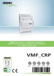
DATI DIMENSIONALI DIMENSIONS DIMENSIONS ABMESSUNGEN DIMENSIONES [mm]<br />
<strong>FCX</strong> 22 ÷ 50 3R <strong>FCX</strong> 62 ÷ 82 3R<br />
404<br />
88<br />
260<br />
153<br />
41<br />
OUT<br />
142<br />
194<br />
IN<br />
Øe 17,5<br />
526<br />
108<br />
273<br />
170<br />
41<br />
OUT<br />
148<br />
194<br />
IN<br />
Øe 17,5<br />
7<br />
Italiano<br />
English<br />
Español Deutsche<br />
Français
Italiano<br />
English<br />
Español Deutsche<br />
Français<br />
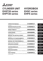
8<br />
B<br />
A<br />
7<br />
11<br />
10<br />
B<br />
A<br />
B<br />
4<br />
A<br />
Fig. 1<br />
Fig. 3<br />
9<br />
1<br />
5<br />
8<br />
6<br />
2<br />
3<br />
1<br />
2<br />
Fig. 2<br />
Fig. 4<br />
Fig. 5
Ø est. 20,5mm<br />
Fig. 6<br />
Fig. 7<br />
Fig. 8<br />
9<br />
Italiano<br />
English<br />
Español Deutsche<br />
Français
Italiano<br />
English<br />
Español Deutsche<br />
Français<br />
SCHEMI ELETTRICI WIRING DIAGRAMS SCHEMAS ELECTRIQUES SCHALTPLÄNE ESQUEMAS ELÉCTRICOS<br />
LEGENDA READING KEY LEGENDE LEGENDE LEYENDA<br />
IG = Interruttore generale Main switch<br />
Interupteur général Hauptschalter Interruptor general<br />
M = Morsettiera Terminal board<br />
Boitier Klemmleiste Caja de conexiones<br />
MS = Microinterruttore Microswitch<br />
Microinterrupteur Mikroschalter Microinterruptor<br />
MV = Motore ventilatore Fan motor Moteur ventilateur<br />
Ventilatormotor Motor ventilador<br />
PE = Collegamento di terra Earth connection<br />
Mise à terre Erdanschluss Toma de tierra<br />
SA = Sonda ambiente Room sensor Sonde ambiante<br />
Raumtemperaturfuhler Sonda ambiente<br />
SC = Scheda di controllo Electronic control board<br />
Platine de contrôle Steuerschaltkreis Tarjeta de control<br />
SW = Sonda minima temperatura acqua<br />
Water low temperature sensor<br />
Sonde eau<br />
Fühler Wassertemperatur<br />
Sonda mínima temperatura del agua<br />
<strong>FCX</strong> <strong>PPC</strong><br />
10<br />
M 1 2 3 4 5 6 7 8 9 10<br />
L N Y N<br />
BL<br />
VC/F<br />
ROS<br />
NE BL<br />
1 3 5 6 7<br />
CLUSTER<br />
5<br />
5<br />
BL NE MA RO<br />
1 2 3 4<br />
1 2 3 4<br />
MAX<br />
MED<br />
MIN<br />
BL NE MA<br />
M<br />
RO<br />
1<br />
MV<br />
6<br />
6<br />
CE<br />
IG<br />
23OV 50Hz<br />
VCF = Valvola solenoide Solenoid valve<br />
Vanne solenoide Magnetventil Válvula solenoide<br />
PE<br />
N<br />
L<br />
SW<br />
= Componenti forniti optional Optional components<br />
Composants en option Optionsteile<br />
Componentes opcionales facilitados<br />
= Collegamenti da eseguire in loco<br />
On-site wiring<br />
Raccordements à effectuer in situ<br />
Vor Ort auszuführende Anschlüsse<br />
Conexiones que deben realizarse in situ<br />
AR = Arancio Orange Orange Orange Naranja<br />
BI = Bianco White Blance Weiss Blanco<br />
BL = Blu Blue Bleu Blau Azul<br />
GR = Grigio Grey Gris Gray Gris<br />
GV = Giallo-Verde Yellow-Green<br />
Jaune-Vert Gelb-Grün Azul-verdoso<br />
MA = Marrone Brown Marron Braun Marrón<br />
NE = Nero Black Noir Schwarz Negro<br />
RO = Rosso Red Rouge Rot Rojo<br />
PXAE<br />
M1<br />
N<br />
L<br />
V1<br />
V2<br />
V3<br />
Y1<br />
Y2<br />
CE<br />
CE<br />
MS<br />
MS<br />
SW<br />
SW<br />
EXT<br />
JP1<br />
INT<br />
-<br />
SA (INT)<br />
Gli schemi elettrici sono soggetti ad un continuo aggiornamento, è obbligatorio quindi fare riferimento a quelli a bordo macchina.<br />
All wiring diagrams are constantly updated. Please refer to the ones supplied with the unit.<br />
Nos schémas électriques étant constamment mis à jour, il faut absolument se référer à ceux fournis à bord de nos appareils.<br />
Die Schaltpläne werden ständig aktualisiert, deswegen muss man sich stets auf das mit dem Gerät gelieferte Schaltschema beziehen.<br />
El cableado de las máquinas es sometido a actualizaciones constantes. Por favor, para cada unidad hagan referencia a los esquemas suministrados con la misma.<br />
+
SCHEMI ELETTRICI WIRING DIAGRAMS SCHEMAS ELECTRIQUES SCHALTPLÄNE ESQUEMAS ELÉCTRICOS<br />
PXAE<br />
M1<br />
F 1A<br />
FC/ 1<br />
FC/ 2<br />
N<br />
L<br />
L PH N N V1 V2 V3 Y1 Y2<br />
INPUT<br />
SIT5<br />
OUTPUT<br />
V3 V2 V1 Y1 Y2<br />
MAX FC/10<br />
+<br />
-<br />
V1<br />
V2<br />
V3<br />
Y1<br />
Y2<br />
CE<br />
CE<br />
MS<br />
MS<br />
F<br />
2A<br />
L = 15m MAX<br />
V1 V2<br />
OUTPUT<br />
V3<br />
SIT3/ 1<br />
V3 V2 V1 N L<br />
NINPUT<br />
PH<br />
F<br />
2A<br />
CE<br />
V1 V2<br />
OUTPUT<br />
V3<br />
SIT3/ 2<br />
L = 100m MAX<br />
V3 V2 V1 N L<br />
NINPUT<br />
PH<br />
MS<br />
MS<br />
SW<br />
SW<br />
SW<br />
EXT<br />
L = 15m MAX<br />
SA (INT)<br />
1 2 3 4 5 6 7 8 9 10<br />
BL NE MA RO<br />
M<br />
JP1<br />
M<br />
1 2 3 4 5 6 7 8 9 10<br />
BL NE MA RO<br />
INT<br />
VC/F VC/F<br />
6<br />
6<br />
1 2 3 4<br />
1 2 3 4<br />
5<br />
5<br />
BL<br />
ROS<br />
L N Y N<br />
6<br />
6<br />
1 2 3 4<br />
1 2 3 4<br />
5<br />
5<br />
BL<br />
ROS<br />
L N Y N<br />
MIN<br />
MED<br />
MAX<br />
MIN<br />
MED<br />
MAX<br />
BL NE MA RO<br />
BL NE MA RO<br />
M<br />
NE BL<br />
M<br />
1 3 5 6 7<br />
1<br />
1<br />
MV MV<br />
1 3 5 6 7<br />
NE BL<br />
FC/ 1<br />
CLUSTER<br />
FC/ 2<br />
CLUSTER<br />
N<br />
L<br />
L N<br />
PE<br />
L N<br />
23OV 50Hz<br />
IG<br />
<strong>FCX</strong> <strong>PPC</strong><br />
SIT5<br />
SIT3<br />
Gli schemi elettrici sono soggetti ad un continuo aggiornamento, è obbligatorio quindi fare riferimento a quelli a bordo macchina.<br />
All wiring diagrams are constantly updated. Please refer to the ones supplied with the unit.<br />
Nos schémas électriques étant constamment mis à jour, il faut absolument se référer à ceux fournis à bord de nos appareils.<br />
Die Schaltpläne werden ständig aktualisiert, deswegen muss man sich stets auf das mit dem Gerät gelieferte Schaltschema beziehen.<br />
El cableado de las máquinas es sometido a actualizaciones constantes. Por favor, para cada unidad hagan referencia a los esquemas suministrados con la misma.<br />
11<br />
Italiano<br />
English<br />
Español Deutsche<br />
Français
Italiano<br />
Conservare i manuali in luogo asciutto, per evitare il deterioramento,<br />
per almeno 10 anni per eventuali riferimenti futuri.<br />
Leggere attentamente e completamente tutte le informazioni<br />
contenute in questo manuale. Prestare particolarmente<br />
attenzione alle norme d’uso accompagnate dalle scritte<br />
“PERICOLO” o “ATTENZIONE” in quanto, se non osservate,<br />
possono causare danno alla macchina e/o a persone e cose.<br />
Per anomalie non contemplate da questo manuale, interpellare<br />
tempestivamente il Servizio Assistenza di zona.<br />
INSTALLAZIONE DELL’UNITÀ<br />
ATTENZIONE: prima di effettuare qualsiasi intervento, assicurarsi<br />
che l’alimentazione elettrica sia disinserita.<br />
ATTENZIONE: i collegamenti elettrici, l’installazione dei ventilconvettori<br />
e dei loro accessori devono essere eseguiti solo<br />
da soggetti in possesso dei requisiti tecnico-professionali di<br />
abilitazione all’installazione, alla trasformazione, all’ampliamento<br />
e alla manutenzione degli impianti ed in grado di verificare<br />
gli stessi ai fini della sicurezza e della funzionalità.<br />
Il ventilconvettore deve essere installato in posizione tale da<br />
consentire facilmente la manutenzione ordinaria (pulizia del<br />
filtro) e straordinaria, nonchè l’accesso alla valvola di sfiato<br />
dell’aria sulla fiancata del telaio (lato attacchi).<br />
Per installare l’unità procedere come segue:<br />
- Estrarre il filtro dell’aria.<br />
- Togliere il pannello di chiusura anteriore nel caso delle versioni<br />
pensili di grandezza da 22 a 50.<br />
- In caso di installazione a parete, si mantenga una distanza<br />
minima dal pavimento di 80 mm. In caso di installazione a<br />
pavimento per mezzo degli zoccoli, si faccia riferimento alle<br />
istruzioni a corredo dell’accessorio.<br />
- Per il fissaggio al muro o al soffitto usare dei tasselli ad espansione<br />
(non forniti) come indicato in Figg. 1 e 2.<br />
Per le versioni pensili, nel caso si utilizzi l’accessorio supporti<br />
(AMP), procedere come segue :<br />
- montare i 4 supporti (1 di Fig. 4) ai lati dell’apparecchio inserendo<br />
nell’apposita feritoia la linguetta superiore e fissando la<br />
COLLEGAMENTI ELETTRICI<br />
ATTENZIONE: prima di effettuare qualsiasi intervento, assicurarsi<br />
che l’alimentazione elettrica sia disinserita.<br />
ATTENZIONE: i collegamenti elettrici, l’installazione dei ventilconvettori<br />
e dei loro accessori devono essere eseguiti solo<br />
da personale specializzato.<br />
CARATTERISTICHE DEI CAVI DI COLLEGAMENTO<br />
Usare cavi tipo H05V-K oppure N07V-K con isolamento<br />
300/500 V incassati in tubo o canalina.<br />
Tutti i cavi devono essere incassati in tubo o canalina finchè<br />
non sono all’interno del ventilconvettore.<br />
I cavi all’uscita dal tubo o canalina devono essere posizionati<br />
in modo da non subire sollecitazioni a trazione o torsione e<br />
comunque protetti da agenti esterni.<br />
Cavi a trefolo possono essere usati solo con capicorda.<br />
Assicurarsi che i trefoli dei fili siano ben inseriti.<br />
Gli schemi elettrici sono soggetti ad un continuo aggiornamento,<br />
è obbligatorio quindi fare riferimento a quelli a bordo<br />
macchina.<br />
Per proteggere l’unità contro i cortocircuiti, montare sulla<br />
linea di alimentazione un interruttore onnipolare magnetotermico<br />
2A 250V (IG) con distanza minima di apertura dei<br />
contatti di 3mm.<br />
I ventilconvettori <strong>FCX</strong> <strong>PPC</strong> richiedono l’abbinamento con<br />
il pannello comandi PXAE (accessorio), per l’installazione e<br />
ROTAZIONE DELLA BATTERIA<br />
Se per motivi di allacciamenti idraulici, si dovesse ruotare la<br />
batteria, dopo aver tolto il pannello di chiusura anteriore, procedere<br />
come segue (Fig. 5):<br />
– togliere la vite (1) che fissa il pannello comandi (2) (se presente)<br />
alla fiancata destra ed estrarlo staccando i collegamenti elettrici;<br />
– togliere la bacinella di raccolta condensa (3);<br />
– togliere il coperchio di chiusura della batteria (4) svitando le viti;<br />
– togliere le viti che fissano la batteria (5) e quindi estrarla;<br />
– rimuovere i semitranciati (6) dalla fiancata destra;<br />
– ruotare la batteria (5) e fissarla con le viti precedentemente tolte;<br />
– rimontare il coperchio (4), fissandolo con le viti, e i tappi in<br />
plastica (7), forniti a corredo, nei fori lasciati liberi dagli attac-<br />
12<br />
L'apparecchio deve essere installato in maniera tale da rendere<br />
possibili operazioni di manutenzione e/o riparazione.<br />
La garanzia dell'apparecchio non copre in ogni caso i costi<br />
dovuti ad autoscale, ponteggi o altri sistemi di elevazione che<br />
si rendesero necessari per effettuare gli interventi in garanzia.<br />
AERMEC S.p.A. declina ogni responsabilità per qualsiasi danno<br />
dovuto ad un uso improprio della macchina, ad una lettura parziale<br />
o superficiale delle informazioni contenute in questo manuale.<br />
Il numero di pagine di questo manuale è: 24.<br />
parte inferiore al frutto per mezzo delle viti a corredo;<br />
- fissare a soffitto le flange (2) mediante tasselli ad espansione<br />
(non forniti); per le posizioni relative tra flange e frutto si vedano<br />
i dati dimensionali.<br />
- Effettuare i collegamenti idraulici.<br />
La posizione e il diametro degli attacchi idraulici sono riportati<br />
nei dati dimensionali.<br />
Si consiglia di isolare adeguatamente le tubazioni dell’acqua o<br />
di installare l’apposita bacinella ausiliaria di raccolta condensa,<br />
disponibile come accessorio, per evitare gocciolamenti durante<br />
il funzionamento in raffreddamento. In caso di installazione<br />
orizzontale, montare il raccordo di scarico della condensa fornito<br />
a corredo secondo quanto illustrato in figura 6. Si abbia cura<br />
di sigillare con silicone la connessione tra bacinella e raccordo.<br />
La rete di scarico della condensa deve essere opportunamente<br />
dimensionata e le tubazioni posizionate in modo da mantenere<br />
lungo il percorso un’adeguata pendenza (min.1%). Nel caso di<br />
scarico nella rete fognaria, si consiglia di realizzare un sifone<br />
che impedisca la risalita di cattivi odori verso gli ambienti.<br />
- Effettuare i collegamenti elettrici secondo quanto riportato<br />
negli schemi elettrici.<br />
- Rimontare l'involucro, o il pannello di chiusura anteriore,<br />
senza dimenticarsi di connettere la sonda ambiente o il<br />
microinterruttore (se presenti).<br />
- Riposizionare il filtro dell’aria.<br />
l’uso prendere visione anche del manuale PXAE.<br />
Ogni pannello comandi può controllare un solo ventilconvettore.<br />
Il luogo di montaggio deve essere scelto in modo che il limite<br />
di temperatura ambiente massimo e minimo venga rispettato<br />
0÷45°C (
INFORMAZIONI IMPORTANTI E MANUTENZIONE<br />
ATTENZIONE: il ventilconvettore è collegato alla rete elettrica<br />
ed al circuito idraulico, un intervento da parte di personale non<br />
provvisto di specifica competenza tecnica può causare danni allo<br />
stesso operatore, all’apparecchio ed all’ambiente circostante.<br />
ALIMENTARE IL VENTILCONVETTORE SOLO CON TENSIO-<br />
NE 230 VOLT MONOFASE<br />
Utilizzando alimentazioni elettriche diverse il ventilconvettore<br />
può subire danni irreparabili.<br />
NON USARE IL VENTILCONVETTORE IN MODO IMPROPRIO<br />
Il ventilconvettore non va utilizzato per allevare, far nascere e<br />
crescere animali.<br />
VENTILARE L'AMBIENTE<br />
Si consiglia di ventilare periodicamente l'ambiente ove è<br />
installato il ventilconvettore, specialmente se nel locale risiedono<br />
parecchie persone o se sono presenti apparecchiature a<br />
gas o sorgenti di odori.<br />
REGOLARE CORRETTAMENTE LA TEMPERATURA<br />
La temperatura ambiente va regolata in modo da consentire il<br />
massimo benessere alle persone presenti, specialmente se si<br />
tratta di anziani, bambini o ammalati, evitando sbalzi di temperatura<br />
tra interno ed esterno superiori a 7 °C in estate.<br />
In estate una temperatura troppo bassa comporta maggiori<br />
consumi elettrici.<br />
ORIENTARE CORRETTAMENTE IL GETTO D'ARIA<br />
L'aria che esce dal ventilconvettore non deve investire direttamente<br />
le persone; infatti, anche se a temperatura maggiore di<br />
quella dell'ambiente, può provocare sensazione di freddo e<br />
conseguente disagio.<br />
NON USARE ACQUA TROPPO CALDA<br />
Per pulire il ventilconvettore usare panni o spugne morbidi<br />
bagnati in acqua al massimo a 40 °C. Non usare prodotti chimici<br />
o solventi per nessuna parte del ventilconvettore. Non spruzzare<br />
acqua sulle superfici esterne o interne del ventilconvettore (si<br />
potrebbero provocare dei corti circuiti).<br />
LIMITI DI FUNZIONAMENTO<br />
Massima temperatura ingresso acqua 80 °C<br />
Massima pressione d'esercizio 8 bar<br />
Minima temperatura media dell’acqua<br />
Per evitare fenomeni di condensazione sulla struttura esterna<br />
dell’apparecchio con ventilatore in funzione, la temperatura<br />
media dell’acqua non deve essere inferiore ai limiti riportati<br />
nella tabella sottostante, che dipendono dalle condizioni<br />
PLASMACLUSTER<br />
La qualità dell’aria trattata è garantita dal sistema di depurazione<br />
“PLASMACLUSTER” che decompone le molecole di<br />
acqua e di ossigeno, normalmente presenti nell’aria ambiente<br />
(“umidità” ed “ossigeno”), in ioni postivi e negativi. Tali ioni<br />
liberati nell’aria andranno ad aderire alle molecole delle<br />
IMBALLO<br />
I ventilconvettori vengono spediti con imballo standard costituito<br />
da gusci di polistirolo espanso e cartone.<br />
PULIRE PERIODICAMENTE IL FILTRO<br />
Una pulizia frequente del filtro garantisce una maggiore ef ficienza<br />
di funzionamento.<br />
Controllare se il filtro risulta molto sporco: nel caso ripetere<br />
l’operazione più spesso.<br />
Pulire frequentemente, togliere la polvere accumulata con un<br />
aspiratore.<br />
Quando il filtro è pulito rimontarlo sul ventilconvettore procedendo<br />
al contrario rispetto allo smontaggio.<br />
PULIZIA STRAORDINARIA<br />
La possibilità di rimuovere le coclee dei ventilatori ispezionabili<br />
(eseguibile solo da personale provvisto di specifica competenza<br />
tecnica) consente di eseguire una pulizia accurata delle<br />
anche delle parti interne, condizione necessaria per installazioni<br />
in luoghi molto affollati o che richiedono uno standard<br />
elevato di igiene.<br />
DURANTE IL FUNZIONAMENTO<br />
Lasciare sempre il filtro montato sul ventilconvettore durante il<br />
funzionamento, altrimenti la polvere presente nell'aria andrà a<br />
sporcare le superfici della batteria.<br />
È NORMALE<br />
Nel funzionamento in raffreddamento può uscire del vapore<br />
acqueo dalla mandata del ventilconvettore.<br />
Nel funzionamento in riscaldamento un leggero fruscio d’aria<br />
può essere avvertibile in prossimità del ventilconvettore.<br />
Talvolta il ventilconvettore può emettere odori sgradevoli dovuti<br />
all'accumulo di sostanze presenti nell'aria dell'ambiente (specialmente<br />
se non si provvede a ventilare periodicamente la<br />
stanza, pulire il filtro più spesso).<br />
Durante il funzionamento si potrebbero avvertire rumori e<br />
scricchiolii interni all'apparecchio dovuti alle diverse dilatazioni<br />
termiche degli elementi (plastici e metallici), ciò comunque non<br />
indica un malfunzionamento e non provoca danni all’unità se non<br />
si supera la massima temperatura dell'acqua di ingresso.<br />
termo-igrometriche dell’aria ambiente.<br />
I suddetti limiti si riferiscono al funzionamento con ventilatore<br />
in moto alla minima velocità.<br />
In caso di prolungata situazione con ventilatore spento e passaggio<br />
di acqua fredda in batteria, è possibile la formazione di<br />
condensa all’esterno dell’apparecchio, pertanto si consiglia<br />
l’inserimento dell’accessorio valvola a tre vie .<br />
MINIMA TEMPERATURA MEDIA ACQUA<br />
Temperatura a bulbo secco dell’aria ambiente °C<br />
21 23 25 27 29 31<br />
15 3 3 3 3 3 3<br />
Temperatura a bulbo umido 17 3 3 3 3 3 3<br />
dell’aria ambiente °C 19 3 3 3 3 3 3<br />
21 6 5 4 3 3 3<br />
23 - 8 7 6 5 5<br />
sostanze inquinanti e ricombinandosi (una volta attivate) le<br />
decompongono in sottoprodotti non tossici (acqua, ossigeno<br />
ed anidride carbonica, etc..).<br />
Il depuratore dell’aria “PLASMACLUSTER” si attiva contemporaneamente<br />
alla ventilazione sia a Caldo che a Freddo.<br />
13<br />
Italiano
English<br />
Store the manuals in a dry location to avoid deterioration, as<br />
they must be kept for at least 10 years for any future reference.<br />
All the information in this manual must be carefully read and<br />
understood. Pay particular attention to the operating standards<br />
with “DANGER” or “WARNING” signals as failure to comply with<br />
them can cause damage to the machine and/or persons or objects.<br />
If any malfunctions are not included in this manual, contact<br />
the local After-sales Service immediately.<br />
The apparatus must be installed in such a way that maintenan-<br />
UNIT INSTALLATION<br />
CAUTION: check that the power supply is disconnected before<br />
performing operations on the unit.<br />
CAUTION: wiring connections installation of the fancoil and<br />
relevant accessories should be performed by a technician who<br />
has the necessary technical and professional expertise to install,<br />
modify, extend and maintain plants and who is able to check the<br />
plants for the purposes of safety and correct operation.<br />
The fancoil should be installed in such a way as to facilitate<br />
routine (filter cleaning) and special maintenance operations,<br />
as well as access to the air breather valve on the side of the<br />
unit frame (connector side).<br />
To install the unit, proceed as follows:<br />
- Extract the air filter.<br />
- Remove the rear cover panel in the case of wall models,<br />
sizes 22 to 50.<br />
- In the case of wall-mounted, keep a minimum clearance of<br />
80 mm from the floor. In the case of floor-mounted units on<br />
bases, refer to the instructions supplied with the accessory.<br />
- Use expansion plugs (not supplied) to secure the unit to the<br />
wall or ceiling, as shown in figures 1 and 2.<br />
To install hanging units with the AMP brackets, proceed as follows:<br />
- fit the 4 brackets (1 in Fig. 4) to the sides of the unit; insert<br />
ELECTRICAL CONNECTIONS<br />
CAUTION: make sure that electrical power to the machine<br />
has been turned off before making electrical connections.<br />
CAUTION: wiring operations and installation of the fancoil<br />
and relative accessories should be performed by specialised<br />
personnel only.<br />
CONNECTION CABLE SPECIFICATIONS<br />
Use H05V-K or N07V-K type with 300/500 V insulation piped<br />
or ducted.<br />
All cables must be piped or ducted until they are not placed<br />
inside the fan coil.<br />
The cables coming out of the pipe/duct must not be subjected to<br />
stretch or twist. They must be protected from weather conditions.<br />
Stranded wires may only be used in connection with terminating<br />
sleeves. It must be ensured that all individual wires are<br />
correctly inserted in the sleeve.<br />
All wiring diagrams are constantly updated. Please refer to the<br />
ones supplied with the unit.<br />
To protect fan coils against short circuits, always fit the power<br />
cable to the units with 2A 250V (IG) thermo-magnetic all-pole<br />
switches with a minimum contact gap of 3 mm.<br />
<strong>FCX</strong> <strong>PPC</strong> fan coils are to be used with PXAE control panel (acces-<br />
ROTATING THE COIL<br />
If connection of utilities to the unit requires rotation of the coil, remove<br />
the front pannel, then proceed as follows (Fig. 5):<br />
– remove the screw (1) securing the control panel (2) (if present)<br />
to the right side of the unit, then remove it after electrical<br />
disconnection;<br />
– remove the condensate tray (3);<br />
– remove the coil cover sheet (4) by removing the screws;<br />
– remove the screws securing the coil (5), then remove it;<br />
– remove the push-outs and the small plate (6) on the right<br />
side;<br />
– rotate the coil (5), then secure it in the new position with the<br />
screws previously removed;<br />
– remount the coil cover sheet (4) and secure it with screws,<br />
then insert the plastic plugs (7) supplied in the openings<br />
left free by the hydraulic connections; after removing the<br />
Plasmacluster use the small plate for closing the hole on the<br />
14<br />
ce and/or repair operations are possible.<br />
The apparatus's warranty does not in any case cover costs due<br />
to automatic ladders, scaffolding or other lifting systems necessary<br />
for carrying out repairs under guarantee.<br />
AERMEC S.p.A. declines all responsibility for any damage whatsoever<br />
caused by improper use of the machine, and a partial<br />
or superficial acquaintance with the information contained in<br />
this manual.<br />
The number of pages in this manual is : 24.<br />
the upper tab in the slot, then secure the lower part to the<br />
contact block by means of the screws supplied;<br />
- secure the flanges (2) to the ceiling by means of expansion<br />
plugs (not supplied); for the positions between the flanges and<br />
the contact block, see the dimensional data.<br />
- Make hydraulic connections.<br />
Refer to the dimensional data for the position and diameter of<br />
the hydraulic connectors.<br />
Insulate water lines adequately or fit the condensate drainage<br />
tray (available as an accessory) to prevent dripping during<br />
cooling applications. In case of horizontal installation, fit the<br />
condensate discharge pipe (supplied separately) following the<br />
indications shown in picture 6. The connection between pipe<br />
and drip tray must be sealed with silicone.<br />
The condensate drainage system should be of an adequate size<br />
and be positioned to favour runoff (min. 1% slope). If condensate<br />
is discharged into the sewage system, install a siphon to<br />
prevent return of unpleasant odour into the room.<br />
- Make the electrical connections as shown in the wiring diagrams.<br />
- Remount the cover, or the front pannel, connect the ambient<br />
sensor or the microswitch (if present).<br />
- Refit the air filter.<br />
sory). Please consult the PXAE booklet for installation and use<br />
Each control panel can control a single fancoil.<br />
The assembling place must be chosen so that the max. and<br />
min. room temperature limit is respected 0÷45°C (
IMPORTANT MAINTENANCE INFORMATION<br />
WARNING: The fancoil is connected to the power supply and<br />
a water circuit. Operations performed by persons without<br />
the required technical skills can lead to personal injury to the<br />
operator or damage to the unit and surrounding objects.<br />
POWER THE FANCOIL WITH SINGLE-PHASE 230 V ONLY<br />
Use of other power supplies could cause permanent damage to<br />
the fancoil.<br />
NEVER USE THE FANCOIL FOR APPLICATIONS FOR WHICH<br />
IT WAS NOT DESIGNED<br />
Do not use the fancoil in husbandry applications (e.g. incubation).<br />
AIR THE ROOM<br />
Periodically air the room in which the fancoil has been installed;<br />
this is particularly important if the room is occupied by<br />
many people, or if gas appliances or sources of odours are<br />
present.<br />
CORRECTLY ADJUST THE TEMPERATURE<br />
Room temperature should be regulated to ensure maximum<br />
comfort to persons present, particularly in the case of the<br />
elderly, infants and invalids. Prevent temperature fluctuations<br />
between indoors and outdoors greater than 7 °C during summer.<br />
Note that very low temperatures during summer will lead to<br />
greater electricity consumption.<br />
ORIENT AIR FLOW CORRECTLY<br />
Air delivered by the fancoil should not be oriented directly at<br />
people; even if air temperature is greater than room temperature,<br />
it can cause a cold sensation and consequently discomfort.<br />
DO NOT USE HOT WATER<br />
When cleaning the indoor unit, use rags or soft sponges soaked<br />
in warm water (no higher than 40°C).<br />
Do not use chemical products or solvents to clean any part of<br />
the fancoil.<br />
OPERATING LIMITS<br />
Maximum water inlet temperature 80 °C<br />
Maximum working pressure 8 bar<br />
Minimum average water temperature<br />
To prevent the formation of condensation on the exterior<br />
of the unit while the fan is operating, the average water<br />
temperature should not drop beneath the limits shown in<br />
the table below, determined by the ambient conditions.<br />
PLASMACLUSTER<br />
The quality of the air treated is guaranteed by the<br />
“PLASMACLUSTER” purifier that breaks down the water and<br />
oxygen molecules , normally present in the air in the room<br />
(“humidity” and “oxygen”), in positive and negative ions.<br />
These ions liberated into the air will stick to the molecules of<br />
PACKING<br />
The units are shipped in cardboard box standard packing and<br />
polystirene shells.<br />
Do not splash water on interior or exterior surfaces of the fancoil;<br />
danger of short circuit.<br />
PERIODICALLY CLEAN THE FILTER<br />
Frequent cleaning of the filter will ensure more efficient unit<br />
operation.<br />
Check whether the filter requires cleaning; if it is particularly<br />
dirty, clean it more often.<br />
Clean the filter frequently. Use a vacuum cleaner to remove<br />
built up dust. Avoid water or detergents if possible since they<br />
greatly accelerate loss of the filter's electrostatic charge.<br />
After cleaning and drying the filter, fit it on the fancoil by following<br />
the removal procedure in reverse order.<br />
SPECIAL CLEANING<br />
The removable drip tray and fan volute ensure thorough cleaning<br />
of the unit (by specifically trained personnel), essential<br />
for installations in venues subject to crowding or in those with<br />
special hygiene requirements.<br />
DURING UNIT OPERATION<br />
Always leave the filter on the fancoil during operation (otherwise<br />
dust in the air could soil the surface of the coil).<br />
IT IS NORMAL<br />
During cooling, water vapour may be present in the air delivery.<br />
During heating operation a light rustling sound may be perceived<br />
near the fancoil.<br />
Sometimes the fancoil can give off unpleasant odours due to<br />
the accumulation of substances present in the room: air the<br />
room and clean the filter more often.<br />
During the operation, there could be noises and creaks inside<br />
the device, due to the various heat expansions of the elements<br />
(plastic and metallic), but this does not indicate any malfunctioning<br />
and does not cause damage to the unit unless the maximum<br />
input water temperature is exceeded.<br />
These limits refer to unit operation with fan at minimum speed.<br />
Note that condensation may form on the exterior of the unit if<br />
cold water circulates through the coil while the fan is off for<br />
prolonged periods of time, so it is advisable to fit the additional<br />
three-way valve.<br />
MINIMUM AVERAGE WATER TEMPERATURE<br />
Dry bulb temperature °C<br />
21 23 25 27 29 31<br />
15 3 3 3 3 3 3<br />
17 3 3 3 3 3 3<br />
Wet bulb temperature °C 19 3 3 3 3 3 3<br />
21 6 5 4 3 3 3<br />
23 - 8 7 6 5 5<br />
the polluting substances and by being recombined (once activated)<br />
decomposes them into non-toxic sub-products (water,<br />
oxygen and carbon dioxide etc..).<br />
The “PLASMACLUSTER” air purifier is activated at the same<br />
time as the ventilation when both hot and cold.<br />
15<br />
English
Français<br />
Conserver les manuels dans un endroit sec, afin d’éviter leur<br />
détérioration, pendant au moins 10 ans, pour toutes éventuelles<br />
consultations futures.<br />
Lire attentivement et entièrement toutes les informations contenues<br />
dans ce manuel. Prêter une attention particulière aux<br />
normes d’utilisation signalées par les inscriptions “DANGER” ou<br />
“ATTENTION”, car leur non observance pourrait causer un dommage<br />
à l’appareil et/ou aux personnes et objets.<br />
Pour toute anomalie non mentionnée dans ce manuel, contacter<br />
aussitôt le service après-vente de votre secteur.<br />
INSTALLATION DE L’UNITE<br />
ATTENTION !: avant d’effectuer une intervention quelconque<br />
s’assurer que l’alimentation électrique est bien désactivée.<br />
ATTENTION: les raccordements électriques, l’installation des<br />
ventiloconvecteurs et de leurs accessoires ne doivent être exécutés<br />
que par des personnes en possession de la qualification<br />
technico-professionnelle requise pour l’habilitation à l’installation,<br />
la transformation, le développement et l’entretien des<br />
installations, et en mesure de vérifier ces dernières aux fins de<br />
la sécurité et de la fonctionnalité.<br />
Le ventiloconvecteur doit être installé dans une position permettant<br />
d'effectuer aisément la maintenance ordinaire (nettoyage du<br />
filtre) et extraordinaire et d'accéder à la soupape d'évent de l'air<br />
sur le côté du châssis (côté raccords).<br />
Pour installer l'unité, procéder comme suit :<br />
- Retirer le filtre de l'air.<br />
- Retirer le panneau de fermeture avant dans le cas des versions<br />
suspendues dans les modèles de 22 à 50.<br />
- En cas d'installation murale, maintenir une distance minimum<br />
au sol de 80 mm. En cas d'installation au sol au moyen des pieds,<br />
faire référence aux instructions accompagnant l'accessoire.<br />
- Pour la fixation au mur ou sur plafond, utiliser des chevilles à<br />
expansion (non livrées) comme indiqué sur les Fig. 1 et 2.<br />
Pour les versions suspendues, si on utilise l'accessoire supports<br />
(AMP), procéder comme suit:<br />
- monter les 4 supports (1 Fig. 4) sur les côtés de l'appareil en<br />
RACCORDEMENTS ELECTRIQUES<br />
ATTENTION: avant d’effectuer une quelconque intervention,<br />
s’assurer que l’alimentation électrique est coupée.<br />
ATTENTION: les raccordements électriques, l'installation des<br />
ventiloconvecteurs et de leurs accessoires ne doivent être exécutés<br />
que par du personnel spécialisé.<br />
CARACTERISTIQUES DES CABLES DE RACCORDEMENT<br />
Utiliser des câbles du type H05V-K ou N07V-K avec isolation<br />
300/500 V en une conduite ou une goulotte.<br />
Tous les câbles doivent être insérés dans des conduites ou goulottes<br />
tant qu'ils se trouvent à l'intérieur du ventilo-convecteur.<br />
A la sortie de la conduite ou de la goulotte, les câbles doivent<br />
être positionnés de façon à ne subir aucune sollicitation telles<br />
que tractions ou torsions et de toutes façons ils doivent être<br />
protégés des agents atmosphériques.<br />
Les câbles tressés doivent être seulement utilisés pour des terminaux<br />
avec douilles. Il faut s’assurer que chaque fil de la tresse<br />
soit correctement inséré dans la douille.<br />
Nos schémas électriques étant constamment mis à jour, il faut<br />
absolument se référer à ceux fournis à bord de nos appareils.<br />
Pour protéger l'unité contre les courts-circuits, montez sur la ligne d'alimentation<br />
un interrupteur omnipolaire magnétothermique 2A 250V<br />
(IG) avec une distance minimum d'ouverture des contacts de 3 mm.<br />
Les ventiloconvecteurs <strong>FCX</strong> <strong>PPC</strong> doivent etre raccordés à un<br />
panneau de commande PXAE (accessoire) pour l’installation et<br />
ROTATION DE LA BATTERIE<br />
Si pour des raisons de raccordements hydrauliques, on doit<br />
retourner la batterie, après avoir enlevé le panneau de fermeture<br />
avant , procéder comme suit :<br />
- Enlever la vis (1) qui fixe le panneau de commande (2) (si présent)<br />
à la façade droite et le retirer en débranchant les cables électriques.<br />
- Déposer le bac des condensats (3).<br />
- Déposer le capot supérieur de la batterie (4) en enlevant les vis.<br />
- Enlever les vis de fixation de la batterie (5) et la déposer.<br />
- Enlever les pastilles prédécoupées et la plaquette (6) du coté gauche.<br />
- Retourner la batterie (5) et la fixer avec ses vis précédemment<br />
retirées.<br />
- Remonter le capot supérieur (4) avec ses vis et les bouchons en<br />
plastique (7) fournis de série dans les trous laissés libres par les rac-<br />
16<br />
Lors de l'installation de l'appareil, il faut prévoir l'espace nécessaire<br />
pour les opérations d'entretien et/ou de réparation.<br />
La garantie de l'appareil ne couvre pas les coûts dérivant de l'utilisation<br />
de voitures avec échelle mécanique, d'échafaudages ou<br />
d'autres systèmes de levée employés pour effectuer des interventions<br />
en garantie.<br />
AERMEC S.p.A. décline toute responsabilité pour tout dommage<br />
dû à une utilisation impropre de l’appareil et à une lecture partielle<br />
ou superficielle des informations contenues dans ce manuel.<br />
Ce manuel se compose de pages: 24.<br />
introduisant la languette supérieure dans la fente prévue à cet<br />
effet et en fixant la partie inférieure au châssis à l'aide des vis<br />
fournies de série;<br />
- fixer les brides (2) sur le plafond à l'aide de chevilles à expansion<br />
(non livrées); pour les positions relatives entre brides et<br />
châssis, voir les dimensions.<br />
- Effectuer les raccordements hydrauliques.<br />
La position et le diamètre des raccords hydrauliques sont indiqués<br />
dans les dimensions.<br />
Il est conseillé d'isoler correctement les tuyauteries de l'eau ou d'installer<br />
le bac auxiliaire de récupération de la condensation, disponible comme<br />
accessoire, pour éviter les égouttements durant le fonctionnement en<br />
refroidissement. En cas d’installation horizontale, monter le raccord<br />
d’écoulement des condensats fourni avec l’appareil comme le montre<br />
la fig.6. Il faudra avoir soin de scéller avec du silicone le raccordement<br />
entre le bac et le raccord. Le réseau d’évacuation de la condensation<br />
doit être convenablement dimensionné et les tuyauteries positionnées<br />
de façon à maintenir une pente correcte (min. 1%) le long du parcours.<br />
En cas d’évacuation dans les égouts, il est conseillé de réaliser un siphon<br />
empêchant les mauvaises odeurs de remonter dans les locaux.<br />
- Effectuer les raccordements électriques comme indiqué sur les<br />
schémas électriques.<br />
- Remonter la carrosserie sans oublier de brancher la sonde de température<br />
ambiante ou le micro-interrupteur (s’ils sont présents).<br />
- Remettre le filtre de l’air.<br />
l’utilisation se rèférer au manuel d’utilisation du PXAE.<br />
Chaque panneau de commande peut contrôler un seul ventiloconvecteur.<br />
Le lieu de montage doit être choisi d’une façon que la limite de temperature<br />
ambient max. et min. soit respectée 0÷45°C (
INFORMATIONS IMPORTANTES SUR LA MAINTENANCE<br />
Le ventilo-convecteur est connecté au réseau électrique et<br />
au circuit hydraulique: l'intervention d'un personnel sans<br />
compétence technique spécifique peut entraîner des blessures<br />
pour l'opérateur ou endommager l'appareil ou le milieu<br />
intéressé.<br />
ALIMENTER LE VENTILO-CONVECTEUR EXCLUSIVEMENT<br />
AVEC UNE TENSION DE 230 VOLTS MONOPHASE<br />
Si l'on utilise des alimentations électriques différentes, le ventilo-convecteur<br />
peut être irrémédiablement endommagé.<br />
NE PAS UTILISER LE VENTILO-CONVECTEUR DE MANIERE<br />
IMPROPRE.<br />
Le ventilo-convecteur ne doit pas être utilisé pour l'élevage, la<br />
naissance ou la croissance d'animaux.<br />
VENTILER LE LOCAL<br />
Nous conseillons de ventiler périodiquement le local où est<br />
installé le ventilo-convecteur, plus spécialement si plusieurs<br />
personnes résident dans le local ou si des appareillages à gaz<br />
ou des sources d'odeurs se trouvent dans le local.<br />
REGLER CORRECTEMENT LA TEMPERATURE<br />
La température ambiante doit être réglée de manière à permettre<br />
le bien-être maximal des personnes présentes, en particulier s'il<br />
s'agit de personnes âgées, d'enfants ou de personnes malades,<br />
en évitant des écarts de température -entre l'intérieur et l'extérieur-<br />
supérieurs à 7 °C en été. En été une température trop<br />
basse entraîne une consommation d'électricité plus importante.<br />
ORIENTER CORRECTEMENT LE JET D'AIR<br />
L'air qui sort du ventilo-convecteur ne doit pas frapper directement<br />
les personnes ; en effet, même si ce jet est à une température<br />
supérieure à celle du local, il peut provoquer une<br />
sensation de froid et donc de malaise.<br />
NE PAS UTILISER DE L'EAU TROP CHAUDE<br />
Pour nettoyer l'intérieur de l'Unité utiliser des chiffons ou des<br />
éponges souples et mouillés avec de l'eau dont la température<br />
maximale ne dépasse pas 40 °C. N'utiliser aucun produit<br />
chimique ou solvant pour nettoyer une partie quelconque du<br />
ventilo-convecteur. Ne pas asperger avec de l'eau les surfaces<br />
externes ou internes du ventilo-convecteur (on pourrait provo-<br />
LIMITES DE FONCTIONNEMENT<br />
Température maximale d'entrée de l'eau 80 °C<br />
Pression maximale de fonctionnement 8 bar<br />
Température minimale moyenne de l’eau<br />
Pour éviter les phénomènes de condensation sur la structure<br />
externe de l'appareil avec le ventilateur en service, la température<br />
moyenne de l'eau ne doit pas être inférieure aux limites<br />
reprises sur le tableau ci-après, qui dépendent des conditions<br />
thermo-hygrométriques de l'air ambiant. Ces limites se réfèrent<br />
PLASMACLUSTER<br />
La qualité de l'air traité est garantie grâce à au système de<br />
dépuration “PLASMACLUSTER” qui décompose les molécules<br />
d'eau et d'oxygène qui sont normalement présentes dans l'air<br />
ambiant (“humidité” et “oxygène”), en ions positifs et négatifs.<br />
Ces ions libérés dans l'air adhéreront aux molécules des sub-<br />
EMBALLAGE<br />
Les convecteurs soufflants sont expédiés dans un emballage standard<br />
composé de coques en polystyrène expansé et en carton.<br />
quer des courts-circuits).<br />
NETTOYER LE FILTRE PERIODIQUEMENT<br />
Un nettoyage fréquent du filtre garantit une meilleure efficacité<br />
de fonctionnement.<br />
Contrôler si le filtre est sale: répéter l'opération plus souvent si<br />
nécessaire.<br />
Nettoyez fréquemment, enlevez la poussière qui s'accumule<br />
avec un aspirateur.<br />
Le remonter sur le ventilo-convecteur en adoptant la procédure<br />
inverse de celle du démontage.<br />
NETTOYAGE EXTRAORDINAIRE<br />
La possibilité d'enlever les vis sans fin des ventilateurs qui<br />
peuvent être inspectés (une opération qui doit être réalisée<br />
uniquement par un personnel doté d'une expérience technique)<br />
permettent d'effectuer un nettoyage soigné des organes<br />
internes également, une condition nécessaire pour une mise en<br />
place dans des locaux très fréquentés ou qui exigent un standard<br />
d'hygiène élevé.<br />
DURANT LE FONCTIONNEMENT:<br />
Laisser toujours le filtre monté sur le ventilo-convecteur durant<br />
le fonctionnement : la poussière qui se trouve dans l'air pourrait,<br />
dans le cas contraire, salir les surfaces de la batterie.<br />
IL EST NORMAL<br />
que durant la fonction de refroidissement, de la vapeur d'eau<br />
soit refoulée du ventilo-convecteur.<br />
Durant le fonctionnement pour le chauffage, une légère brise<br />
d'air peut être perçue à proximité du ventilo-convecteur.<br />
Quelquefois le ventilo-convecteur peut émettre des odeurs<br />
désagréables dues à l'accumulation de substances présentes<br />
dans l'air ambiant (plus spécialement si le local n'est pas périodiquement<br />
ventilé ; nettoyer le filtre plus souvent).<br />
Durant le fonctionnement on peut entendre des bruits et des<br />
craquements internes dus aux différentes dilatations thermiques<br />
des éléments (en plastique ou en métal), cela n’indique<br />
pas un dysfonctionnement et ni ne provoque aucun dommage<br />
à l’unité si l’on ne dépasse pas la température maximale de<br />
l’eau en entrée.<br />
au fonctionnement avec un ventilateur en mouvement à la<br />
vitesse minimale. En cas de situation prolongée avec le ventilateur<br />
éteint et le passage de l'eau froide dans la batterie, de la<br />
buée peut se former à l'extérieur de l'appareil , il est conseillé<br />
d'insérer l'accessoire vanne 3 voies.<br />
TEMPÉRATURE MINIMUM MOYENNE DE L’EAU<br />
Température bulbe sèche °C<br />
21 23 25 27 29 31<br />
15 3 3 3 3 3 3<br />
17 3 3 3 3 3 3<br />
Température bulbe humide °C 19 3 3 3 3 3 3<br />
21 6 5 4 3 3 3<br />
23 - 8 7 6 5 5<br />
stances polluantes et en se recombinant (une fois activées) les<br />
décomposent en sous-produits non toxiques (eau, oxygène et<br />
anhydride carbonique, etc..).<br />
Le dépurateur de l'air“PLASMACLUSTER” s'active en même<br />
temps que la ventilation aussi bien à chaud qu'à froid.<br />
17<br />
Français
Deutsche<br />
Bewahren Sie die Gebrauchsanleitungen mindestens 10 Jahre für<br />
eventuelles zukünftiges Nachschlagen an einem trockenen Ort auf.<br />
Alle in diesem Handbuch enthaltenen Informationen aufmerksam<br />
und vollständig lesen. Insbesondere auf die<br />
Benutzungsanweisungen mit den Hinweisen "VORSICHT" oder<br />
"ACHTUNG" achten, da deren Nichtbeachtung Schäden am<br />
Gerät bzw. Sach- und Personenschäden zur Folge haben kann.<br />
Bei Betriebsstörungen, die in dieser Gebrauchsanweisung nicht aufgeführt<br />
sind, wenden Sie sich umgehend an die zuständige Kundendienststelle.<br />
INSTALLATION DER EINHEIT<br />
ACHTUNG: Vergewissern Sie sich, dass die Stromversorgung des<br />
Gerätes unterbrochen ist, bevor Sie Eingriffe an demselben vornehmen.<br />
ACHTUNG: Der Stromanschluß sowie die Installation der<br />
Gebläsekonvektoren und deren Zubehörteile darf nur von<br />
qualifizertem Fachpersonal durchgeführt werden, das die<br />
technisch-professionellen Fähigkeiten für die Installation, den<br />
Umbau, die Erweiterung und die Wartung von Anlagen besitzt<br />
und fähig ist, solche Anlagen auf Sicherheitsanforderungen und<br />
Funktionstüchtigkeit zu überprüfen.<br />
Der Einbau des Gebläsekonvektors soll die regelmäßige<br />
(Filterreinigung) und außerplanmäßige Wartung sowie den<br />
Zugriff des Entlüftungsventils auf Rahmenseite (Anschlußseite)<br />
problemlos gestatten.<br />
Die Einheit wird folgendermaßen installiert:<br />
- Luftfilter ausziehen.<br />
- Gehäuse bzw. vordere Abdeckung in Deckenmodellen Größe<br />
22 bis 50 durch Losdrehen der Schrauben abnehmen.<br />
- Bei Wandinstallation ist eine Bodenhöhe von mindestens 80<br />
mm vorgeschrieben. Für Bodeninstallationen auf Sockel wird auf<br />
die beiliegenden Zubehöranleitungen verwiesen.<br />
- Zur Wand- und Deckenbefestigung mit (nicht beigestellten)<br />
Dübeln gemäß Abb. 1, 2 vorgehen.<br />
Bei Deckenmodellen mit Zubehör AMP wie folgt verfahren:<br />
- die 4 Halter (1 in Abb. 4) mit der oberen Lasche in den ent-<br />
ELEKTRISCHE ANSCHLÜSSE<br />
ACHTUNG: vor dem Beginn der Arbeiten überprüfen, ob die<br />
Stromversorgung abgeschaltet ist.<br />
ACHTUNG: der Stromanschluss sowie die Installation der<br />
Gebläsekonvektoren und deren Zubehörteile darf nur von qualifiziertem<br />
Fachpersonal durchgeführt werden.<br />
MERKMALE DER ANSCHLUSSKABEL<br />
Bei Verlegung im Rohr oder im Kanal Kabel vom Typ H05V-K oder<br />
N07V-K mit Isolierung 300/500 V verwenden.<br />
Alle Kabel bis zum Gebläsenkonvektor müßen im Rohr oder im<br />
Kanal eingelassen sein.<br />
Die Kabel, die vom Rohr oder vom Kanal ausgehen, müßen unter<br />
keine Zugkraft oder Drehung untergestellt sein und auf jeden Fall<br />
müßen sie gegen Witterungseinflüsse geschützt sein.<br />
Litzen dürfen nur in Verbindung mit Aderendhülsen verwendet<br />
werden. Dabei ist sicherzustellen, dass sich alle Litzendrähte sauber<br />
in der Hülse befinden.<br />
Die Schaltpläne werden ständig aktualisiert, deswegen muss man<br />
sich stets auf das mit dem Gerät gelieferte Schaltschema beziehen.<br />
Um die Einheit vor Kurzschlüssen zu schützen, ist ein allpoliger<br />
FI-Schalter 2A 250V (IG) mit einem Mindestabstand<br />
der Kontaktöffnung von 3mm in der Netzleitung zu montieren.<br />
Die passende Fernbedienung für die Gebläsekonvektoren <strong>FCX</strong> <strong>PPC</strong><br />
ist das Mod. PXAE (als Zubehör erhältlich- siehe bitte entsprechende<br />
IDREHEN DER BATTERIE<br />
Ist bedingt durch die Anordnung der Wasseranschlüsse die<br />
Drehung der Batterie erforderlich, ist nach Wegnahme der<br />
Verkleidung wie folgt zu verfahren (Abb. 5):<br />
– Die Schraube lösen (1), die das Schaltfeld (2) (falls vorgesehen) an<br />
der rechten Seite befestigt und es durch Trennen der elektrischen<br />
Anschlüsse herausziehen;<br />
– das Schutzblech der Batterie und, falls vorhanden, die<br />
Kondensatauffangschale abnehmen (3);<br />
– das Batterieverschlußblech (4) durch Lösen der Schrauben abnehmen;<br />
– die Befestigungsschrauben (5) der Batterie lösen und sie herausnehmen;<br />
– die Vorstanzungen und das viereckige Abdeckblech (6) von der<br />
rechten Seite abnehmen;<br />
– die Batterie (5) drehen und mit den zuvor abgenommenen<br />
Schrauben befestigen;<br />
– das Verschlußblech (4) wieder anbringen und mit den Schrauben<br />
befestigen, die mitgelieferten Plastikstöpsel (7) in die freigewordenen<br />
Öffnungen einsetzen; das viereckige Abdeckblech in die durch<br />
18<br />
Das Gerät so aufstellen, dass Instandhaltungs- und/oder<br />
Reparaturarbeiten durchgeführt werden können.<br />
Die Garantie des Gerätes deckt in keinem Fall Kosten für<br />
Feuerwehrleitern, Gerüste oder andere Hebesysteme ab, die sich<br />
für die Garantiearbeiten als erforderlich erweisen sollten.<br />
Die AERMEC S.p.A. übernimmt keine Haftung für Schäden aus dem<br />
unsachgemäßen Gebrauch des Gerätes und der teilweisen oder oberflächlichen<br />
Lektüre der in diesem Handbuch enthaltenen Informationen.<br />
Die Seitenanzahl diese Handbuches ist: Nr. 24 Seiten<br />
sprechenden Schlitz einschieben, die Unterseite mit den mitgelieferten<br />
Schrauben am Innenteil anschrauben<br />
- Flansche (2) mit (nicht beigestellten) Dübeln an der Decke<br />
befestigen. Daten zur relativen Position von Flanschen und<br />
Innenteil finden Sie unter Abmessungen.<br />
- Wasseranschlüsse vornehmen.<br />
Lage und Durchmesser der Wasseranschlüsse, vgl.<br />
Abmessungen.<br />
Wasserleitungen entsprechend isolieren bzw. zusätzliche<br />
Kondensatwanne (Sonderzubehör) zum Tropfschutz im<br />
Kühlbetrieb installieren.<br />
Bei horizontaler Installation, die separatmitgelieferte<br />
Verschraubung für den Kondensatablass wie nach Abb. 6 montieren.<br />
Bitte die Verbindung Kondensatwanne - Verschraubung<br />
mit Silicon versiegeln. Das Kondensatablaßnetz muß genau<br />
bemessen und die Leitungen so verlegt werden, daß während<br />
des gesamten Verlaufs eine ausreichende Neigung (min.<br />
1%) vorhanden ist. Bei Ablaß in das Abwassernetz wird die<br />
Ausführung eines Siphons empfohlen, der das Hochsteigen<br />
unangenehmer Gerüche in die Räume vermeidet .<br />
- Die Stromanschlüsse wie in den Schaltplänen dargestellt ausführen.<br />
- Die Verkleidung wieder anbringen, den Raumfühler oder den<br />
Mikroschalter (falls vorhanden) anschließen.<br />
- Den Luftfilter wieder einsetzen.<br />
Installations- und Bedienungsanleitung).<br />
Jedes Bedienfeld dient zur Steuerung nur eines Gebläsekonvektors.<br />
Der Montage-Ort muss so gewählt sein, dass die obere Arbeitstemperatur-<br />
Grenze nicht überschritten und die unterer Arbeitstemperatur-Grenze<br />
nicht unterschritten wird 0÷45°C (
WICHTIGE HINWEISE UND WARTUNG<br />
ACHTUNG: der Gebläsekonvektor ist sowoul an das<br />
Stromnetz wie auch an die Wasserversorgung angeschlossen;<br />
Eingriffe durch Personen ohne spezifische technische<br />
Fachkenntnisse können zu Personenverletzungen und zu<br />
Maschinen- und Umweltschäden führen.<br />
DER GEBLÄSEKONVEKTOR DARF NUR MIT<br />
WECHSELSPANNUNG 230 VOLT BETRIEBEN WERDEN<br />
Jede andere Netzspannung kann zu nicht wiedergutzumachenden<br />
Schäden des Gebläsekonvektors führen.<br />
DEN GEBLÄSEKONVEKTOR NIE AUF UNZULÄSSIGE WEISE<br />
VERWENDEN<br />
Der Gebläsekonvektor darf nicht für die Aufzucht von Tieren<br />
eingesetzt werden.<br />
RAUMBELÜFTUNG<br />
Es wird empfohlen, den Raum, in dem der Gebläsekonvektor<br />
installiert wird, regelmäßig zu lüften, ganz besonders<br />
wenn der Raum stark frequentiert wird oder Gasgeräte und<br />
Geruchsquellen vorhanden sind.<br />
KORREKTE TEMPERATUREINSTELLUNG<br />
Die Raumtemperatur sollte so eingestellt werden, dass maximales<br />
Wohlbefinden der anwesenden Personen gewährleistet<br />
ist; im Sommer sollten Temperaturunterschiede von mehr als<br />
7°C zwischen Innen und Außen vermieden werden, ganz<br />
besonders für ältere Personen, Kranke und Kinder. Zu niedrige<br />
Temperaturen im Sommer führen außerdem zu einem erhöhten<br />
Energieverbrauch.<br />
KORREKTE EINSTELLUNG DES LUFTSTROMS<br />
Der vom Gebläsekonvektor kommende Luftstrom sollte<br />
nicht direkt auf die Personen gerichtet sein; selbst wenn die<br />
Temperatur des Luftstroms höher als die des Raums ist, kann er<br />
Kälteempfinden und Unbehagen verursachen.<br />
NIE ZU WARMES WASSER BENUTZEN<br />
Das Innere der Einheit mit einem in warmem Wasser angefeuchteten<br />
(max. 40 °C) Lappen oder Schwamm reinigen. Nie<br />
chemische Produkte oder Lösemittel für die Reinigung des<br />
Gebläsekonvektors verwenden. Nie Wasser auf die Außenoder<br />
Innenflächen des Gerätes spritzen (Kurzschlussgefahr).<br />
GRENZWERTE FÜR DEN GERÄTEBETRIEB<br />
Maximale Wassereintrittstemperatur 80 °C<br />
Maximaler Betriebsdruck 8 bar<br />
Minimale mittlere Wassertemperatur<br />
Zur Vermeidung von Kondenswasserbildung auf der<br />
Geräteaußenseite während des Gebläsebetriebs darf die durchschnittliche<br />
Wassertemperatur nicht niedriger als die in der<br />
unten stehenden Tabelle aufgeführten Grenzwerte sein, die<br />
von den thermohygrometrischen Raumbedingungen abhängen.<br />
PLASMACLUSTER<br />
Die Qualität der aufbereiteten Luft vom Reinigungssystem<br />
“PLASMACLUSTER” eindringen können, dass die Wasser- und<br />
Sauerstoffmoleküle in positive und negative Ionen zerlegt, die<br />
normalerweise in der Raumluft vorhanden sind ("Feuchtigkeit"<br />
und "Sauerstoff"). Diese in der Luft freigesetzten Ionen haften an<br />
den verschmutzenden Substanzen und zersetzen diese, nach<br />
VERPACKUNG<br />
Die Gebläsekonvektoren werden in einer Standard verpackung<br />
aus Polystyrol-Schutzschalen und Karton geliefert.<br />
REGELMÄSSIG DEN FILTER REINIGEN<br />
Regelmäßiges Reinigendes Luftfilters gewährleistet einen dauerhaften<br />
störungsfreien Betrieb.<br />
Prüfen Sie dabei den Verschmutzungsgrad: bei starker<br />
Verschmutzung den Filter häufiger säubern.<br />
Den Filter mit einem Staubsauger und bei Bedarf mit Wasser<br />
und einem neutralen Reinigungsmittel reinigen. Nach der<br />
Reinigung und dem Trocknen des Filters den Filter wieder in<br />
den Gebläsekonvektor einbauen und dabei in umgekehrter<br />
Reihenfolge zum Ausbau vorgehen.<br />
AUSSERGEWÖHNLICHE REINIGUNGSARBEITEN<br />
Nach Ausbau der Kondensatwanne und der inspizierbaren<br />
Ventilatorschnecken (diese Arbeiten dürfen nur von Personen<br />
mit spezifischen Fachkenntnissen ausgeführt werden) kann<br />
auch eine sorgfältige Reinigung der Innenteile des Gerätes vorgenommen<br />
werden; solche Arbeiten sind für Installationen in<br />
stark frequentierten Räumen und in solchen, die einen hohen<br />
Hygienestandard erfordern, notwendig.<br />
WÄHREND DES BETRIEBS<br />
Benutzen Sie den Gebläsekonvektor nie ohne Filter, da<br />
sonst der in der Luft schwebende Staub das Register des<br />
Wärmetauschers verschmutzt.<br />
NORMALE ERSCHEINUNG<br />
Beim Kühlbetrieb kann Wasserdampf aus dem Auslass des<br />
Gebläsekonvektors austreten.<br />
Beim Heizbetrieb kann ein leichtes Rauschen der Luft in der<br />
Nähe des Gebläsekonvektors zu vernehmen sein. Mitunter<br />
kann der Gebläsekonvektor unangenehme Gerüche verbreiten,<br />
die durch die Anhäufung von in der Raumluft enthaltenen<br />
Stoffen verursacht werden (ganz besonders bei unzureichender<br />
Raumlüftung oder Filterreinigung).<br />
Während des Betriebs können Geräusche und Knistern<br />
im Gerät zu vernehmen sein, die auf den verschiedenen<br />
Wärmeausdehnungen der Elemente (aus Kunststoff und Metall)<br />
beruhen. Dies ist jedoch kein Anzeichen für eine Störung und<br />
bewirkt keine Schäden am Gerät, wenn die Höchsttemperatur<br />
des Wassers am Eingang nicht überschritten wird.<br />
Die genannten Grenzwerte beziehen sich auf den Gerätelauf<br />
mit Mindestdrehzahl. Bei längerem Gebläsestillstand und gleichzeitigem<br />
Kaltwasserdurchfluss durch das Register kann es auf<br />
der Geräteaußenseite zur Kondenswasserbildung kommen, als<br />
Zubehör das Dreiwege-Ventil einzubauen.<br />
MINIMALE MITTLERE WASSERTEMPERATUR<br />
Temperatur T.K. °C<br />
21 23 25 27 29 31<br />
15 3 3 3 3 3 3<br />
17 3 3 3 3 3 3<br />
Temperatur F.K. °C 19 3 3 3 3 3 3<br />
21 6 5 4 3 3 3<br />
23 - 8 7 6 5 5<br />
ihrer erneuten Zusammensetzung (nach dem Aktivieren) in<br />
ungiftige Nebenprodukte (Wasser, Sauerstoff und Kohlendioxid,<br />
usw.).<br />
Der Luftfilter “PLASMACLUSTER” schaltet sich sowohl im<br />
Heiz- als auch Kühlbetrieb gleichzeitig mit der Lüftung ein.<br />
19<br />
Deutsche
Español<br />
Guarde los manuales en un lugar seco para evitar su deterioro, al<br />
menos durante 10 años, por si fuera posible consultarlos en el futuro.<br />
Leer atenta y completamente todas las informaciones contenidas<br />
en este manual. Preste particular atención a las normas<br />
de uso acompañadas de las indicaciones “PELIGRO” o<br />
“ATENCIÓN” puesto que, si no se cumplen, pueden causar el<br />
deterioro de la máquina y/o daños personales y materiales.<br />
En caso de anomalías no contempladas en este manual, contacte<br />
inmediatamente con el Servicio de Asistencia de su zona.<br />
El aparato debe ser instalado de manera que haga posibles las<br />
INSTALACIÓN DE LA UNIDAD<br />
ATENCIÓN: antes de llevar a cabo ninguna intervención,<br />
asegúrese de que la alimentación eléctrica esté desactivada.<br />
ATENCIÓN: las conexiones eléctricas, la instalación de los fan<br />
coils y de sus accesorios deben ser efectuadas sólo por personas<br />
que posean los requisitos técnico-profesionales de habilitación<br />
para la instalación, la transformación, la ampliación y el mantenimiento<br />
de las instalaciones y que sean capaces de verificar la<br />
seguridad y la funcionalidad de las mismas.<br />
El fan coil debe instalarse en una posición que permita realizar<br />
fácilmente el mantenimiento ordinario (limpieza del filtro) y<br />
extraordinario, y también acceder a la válvula de salida de aire<br />
situada en el lateral del chasis (lado de las conexiones).<br />
Para instalar el equipo, proceda del modo siguiente:<br />
- Extraiga el filtro de aire.<br />
- Quite el panel de cierre frontal.<br />
- Para el montaje en la pared, deje una distancia mínima de<br />
80 mm del suelo. Para la instalación en el suelo sobre zócalos,<br />
consulte las instrucciones que se entregan con estos accesorios.<br />
- Fije el equipo a la pared o al suelo con tornillos de expansión<br />
(no suministrados) como ilustran las Fig. 1 y 2.<br />
Para instalar unidades colgantes con soportes AMP, proceda<br />
como sigue:<br />
- Monte los cuatro soportes (1, Fig. 4) en los laterales del equipo.<br />
Inserte la pestaña superior en la ranura correspondiente y<br />
CONEXIONES ELÉCTRICAS<br />
ATENCIÓN: antes de efectuar las conexiones eléctricas,<br />
asegúrese de que el equipo esté desconectado del suministro<br />
eléctrico.<br />
ATENCIÓN: las conexiones eléctricas y la instalación de los<br />
fan coils y de sus accesorios deben ser realizadas exclusivamente<br />
por personal especializado.<br />
CARACTERÍSTICAS DE LOS CABLES DE CONEXIÓN<br />
Utilice cables H05V-K o N07V-K con aislamiento para<br />
300/500 V, tendidos dentro de un tubo o de una canaleta.<br />
Todos los cables deben pasar por un tubo o una canaleta hasta<br />
el interior del fan coil.<br />
A la salida del tubo o de la canaleta, disponga los cables de<br />
manera tal que no sufran tracciones ni torsiones y queden protegidos<br />
de los agentes externos.<br />
Los cables trenzados pueden utilizarse solamente con terminales<br />
de manguito. Asegúrese de que todos los hilos del cable<br />
estén bien insertados en el manguito.<br />
El cableado de las máquinas es sometido a actualizaciones constantes.<br />
Por favor, para cada unidad hagan referencia a los esquemas<br />
suministrados con la misma.<br />
Para proteger la unidad contra los cortocircuitos, montar en la<br />
línea de alimentación un interruptor omnipolar magnetotérmico<br />
2A 250V (IG) con distancia mínima de apertura de los contactos<br />
de 3 mm.<br />
ROTACIÓN DE LA BATERÍA<br />
Si desea girar la batería para facilitar las conexiones hidráulicas,<br />
quite el panel de cierre frontal y proceda como sigue (Fig. 5):<br />
- extraiga el tornillo (1) que fija el panel de mandos (2) -si está<br />
presente- al lateral derecho, separe las conexiones eléctricas y<br />
saque el panel;<br />
- quite la bandeja de condensados (3);<br />
- afloje los tornillos y quite la tapa de la batería (4);<br />
- quite los tornillos que fijan la batería (5) y extráigala;<br />
- rompa los troquelados y la plaquita (6) del lateral derecho;<br />
- gire la batería (5) y fíjela con los mismos tornillos;<br />
- coloque la tapa (4) con sus tornillos e inserte los tapones de<br />
plástico (7), suministrados de serie, en los agujeros donde estaban<br />
las conexiones hidráulicas; cierre el orificio dejado por el<br />
Plasmacluster sobre el lateral izquierdo con la plaquita.<br />
20<br />
operaciones de mantenimiento y/o reparación.<br />
En cualquier caso, la garantía del aparato no cubre los costes<br />
derivados del uso de escaleras automáticas, andamios u otros<br />
sistemas de elevación necesarios para efectuar las intervenciones<br />
en garantía.<br />
AERMEC S.p.A. declina cualquier responsabilidad por cualquier<br />
daño debido a un uso impropio de la máquina, o bien a<br />
una lectura parcial o superficial de las informaciones contenidas<br />
en este manual.<br />
Número de páginas de este manual: 24.<br />
fije la parte inferior al chasis con los tornillos suministrados.<br />
- Asegure las bridas (2) al techo con tornillos de expansión (no<br />
suministrados). Para las posiciones relativas entre las bridas y<br />
el chasis, vea el apartado Dimensiones.<br />
- Realice las conexiones hidráulicas.<br />
Para la posición y el diámetro de las conexiones hidráulicas,<br />
vea el apartado Dimensiones.<br />
Se aconseja aislar convenientemente los tubos del agua o montar<br />
la bandeja de condensados auxiliar (disponible como accesorio)<br />
para evitar el goteo durante la refrigeración.<br />
En caso de instalación horizontal, monte el empalme para el<br />
desagüe de condensados (suministrado aparte) como se indica<br />
en la figura 6. Selle con silicona la conexión entre la bandeja<br />
y el empalme de desagüe.<br />
El sistema de desagüe de condensados ha de estar correctamente<br />
dimensionado y los tubos deben tener una pendiente del<br />
1% como mínimo en todo su recorrido. Si los condensados se<br />
descargan en la red de saneamiento, instale un sifón para prevenir<br />
el retorno de olores desagradables.<br />
- Realice las conexiones eléctricas como indican los esquemas<br />
eléctricos.<br />
- Monte la envolvente, o el panel frontal, y conecte la sonda<br />
ambiente o el microinterruptor (si se utilizan).<br />
- Coloque el filtro de aire.<br />
El fan-coil <strong>FCX</strong> <strong>PPC</strong> requiere su montaje con el panel de mados<br />
PXAE (accesorio), para su instalación y uso consulte también el<br />
manual PXAE.<br />
Cada panel de mandos puede controlar un solo fan coil.<br />
Instale el equipo en un lugar donde se cumplan los límites máximo<br />
y mínimo de temperatura ambiente 0°C÷45°C (
INFORMACIONES IMPORTANTES Y MANTENIMIENTO<br />
ATENCIÓN: El fan coil está conectado a la red eléctrica y al circuito<br />
hidráulico, una intervención por parte de personal que no<br />
esté provisto de la competencia técnica específica puede causar<br />
daños al operador mismo, al aparato y al medio ambiente que le<br />
rodea.<br />
ALIMENTAR EL FAN COIL SÓLO CON TENSIÓN DE 230<br />
VOLT. MONOFASE<br />
Usando alimentaciones eléctricas distintas el fan coil puede<br />
sufrir daños irreparables.<br />
NO USAR EL FAN COIL DE MANERA INCORRECTA<br />
El fan coil no se debe usar para criar o ayudar a nacer y crecer<br />
animales.<br />
VENTILAR EL AMBIENTE<br />
Se aconseja ventilar periódicamente el ambiente donde está<br />
instalado el fan coil, especialmente si en el local se encuentran<br />
muchas personas, aparatos a gas o aparatos que puedan<br />
causar olores.<br />
REGULAR CORRECTAMENTE LA TEMPERATURA<br />
La temperatura ambiente se regula de manera que permita el<br />
máximo bienestar a las personas presentes, especialmente si se<br />
trata de ancianos, niños o enfermos, evitando cambios bruscos<br />
de temperatura entre el interior y el exterior superiores a 7 °C<br />
en verano.<br />
En verano una temperatura demasiado baja conlleva un mayor<br />
consumo eléctrico.<br />
ORIENTAR CORRECTAMENTE EL CHORRO DE AIRE<br />
El aire que sale del fan coil no debe caer directamente sobre las<br />
personas; de hecho, aunque el aire estuviera a una temperatura<br />
mayor que la temperatura ambiente, puede provocar sensación<br />
de frío y de malestar.<br />
NO USAR AGUA DEMASIADO CALIENTE<br />
Para limpiar la unidad interna usar paños o esponjas mojadas en<br />
agua con una temperatura máxima de 40 °C. No usar productos<br />
químicos o disolventes en ninguna parte del fan coil. No rociar<br />
agua sobre las superficies externas o internas del fan coil (se<br />
pueden provocar cortocircuitos).<br />
LÍMITES DE FUNCIONAMIENTO<br />
Máxima temperatura entrada agua 80 °C<br />
Máxima presión de funcionamiento 8 bar<br />
Mínima temperatura media del agua<br />
Para evitar fenómenos de condensación en la estructura externa<br />
del aparato con el ventilador en funcionamiento, la temperatura<br />
media del agua no debe ser inferior a los límites presentados<br />
en la figura inferior, que dependen de las condiciones<br />
termo-higrométricas del aire del ambiente.<br />
PLASMACLUSTER<br />
La calidad del aire tratada está garantizada por el sistema<br />
de depuración “PLASMACLUSTER” descompone las moléculas<br />
de agua y de oxigeno, normalmente presentes en el aire<br />
ambiente (“humedad" y “oxígeno”), en iones positivos y negativos.<br />
Estos iones liberados en el aire aportarán a las molécu-<br />
LIMPIAR PERIÓDICAMENTE LOS FILTROS<br />
Una limpieza frecuente del filtro garantiza una mayor eficacia<br />
en el funcionamiento.<br />
Comprobar si el filtro está muy sucio: si así fuera, repetir la<br />
operación más a menudo.<br />
Limpiar frecuentemente, quitar el polvo acumulado con un<br />
aspirador, el uso de agua y detergentes acelera considerablemente<br />
el decaimiento de la pre-carga electroestática.<br />
Cuando el filtro esté limpio volver a montarlo en el fan coil<br />
procediendo de manera contraria a su desmontaje.<br />
LIMPIEZA A FONDO<br />
La posibilidad de extraer la cubeta y los husillos de los ventiladores<br />
inspeccionables (operaciones a realizar sólo por personal<br />
provisto de la competencia técnica específica) permiten<br />
realizar una limpieza en profundidad de las partes internas,<br />
condición necesaria para instalaciones en lugares muy concurridos<br />
o que requieren un elevado estándar de higiene.<br />
DURANTE EL FUNCIONAMIENTO<br />
Dejar siempre el filtro montado en el fan coil durante el funcionamiento,<br />
en caso contrario el polvo presente en el aire<br />
ensuciará las superficies de la batería.<br />
ES NORMAL<br />
En el funcionamiento en frío puede salir vapor ácueo de la<br />
boca de envío del fan coil.<br />
En el funcionamiento en calor se puede advertir un ligero<br />
soplido de aire estando cerca del fan coil.A veces el fan coil<br />
podría emitir olores desagradables debido a la acumulación de<br />
sustancias presentes en el aire ambiente (especialmente si no<br />
se procede a ventilar periódicamente la habitación, limpiar el<br />
filtro más a menudo).<br />
Durante el funcionamiento podrían advertirse ruidos y chasquidos<br />
dentro del aparato debidos a las diferentes dilataciones<br />
térmicas de los elementos (plásticos y metálicos), de todas<br />
formas, esto no indica un mal funcionamiento y no provoca<br />
daños a la unidad si no se supera la máxima temperatura del<br />
agua de entrada.<br />
Los antedichos límites se refieren al funcionamiento con ventilador<br />
en movimiento a la velocidad mínima.<br />
En caso de prolongada situación con ventilador apagado y<br />
paso de agua fría en batería, es posible que se forme condensación<br />
en la parte externa del aparato; por lo tanto, se recomienda<br />
la inserción del accesorio válvula de tres vías.<br />
MÍNIMA TEMPERATURA MEDIA DEL AGUA<br />
Temperatura con bulbo seco del aire del ambiente °C<br />
21 23 25 27 29 31<br />
15 3 3 3 3 3 3<br />
Temperatura con bulbo húmedo<br />
del aire del ambiente °C<br />
17<br />
19<br />
21<br />
3<br />
3<br />
6<br />
3<br />
3<br />
5<br />
3<br />
3<br />
4<br />
3<br />
3<br />
3<br />
3<br />
3<br />
3<br />
3<br />
3<br />
3<br />
23 - 8 7 6 5 5<br />
las sustancias contaminantes y volviéndose a combinar (una<br />
vez activadas) las descomponen en subproductos no tóxicos<br />
(agua, oxígeno, anhídrido de carbono, etc.)<br />
El depurador de aire “PLASMACLUSTER” se activa al mismo<br />
tiempo que la ventilación, tanto en Calor como en Frío.<br />
EMBALAJE<br />
Los fan coils se suministran en embalajes estándares formados por topes de poliestireno y caja de cartón.<br />
21<br />
Italiano<br />
Español
Italiano<br />
English<br />
Español Deutsche<br />
Français<br />
PROBLEMA PROBLEM<br />
PROBLEME PROBLEM<br />
PROBLEMA<br />
Poca aria in uscita.<br />
Feeble air discharge.<br />
Il y a peu d’air en sortie.<br />
Schwacher Luftstrom am<br />
Austritt.<br />
Poco aire en salida.<br />
Non fa caldo.<br />
It does not heat.<br />
Pas de chaleur.<br />
Keine Heizung.<br />
No hace calor.<br />
Non fa freddo.<br />
It does not cool.<br />
Pas de froid.<br />
Keine Kühlung.<br />
No hace frío.<br />
Il ventilatore non gira.<br />
The fan does not turn.<br />
Le ventilateur ne tourne pas.<br />
Ventilator Arbeitet nicht.<br />
El ventilador no gira.<br />
Fenomeni di condensazione<br />
sulla struttura esterna dell’apparecchio.<br />
Condensation on the unit<br />
cabinet.<br />
Phénomènes de condensation<br />
sur la structure exterieure<br />
de l’appareil.<br />
Kondenswasserbildung am<br />
Gerät.<br />
Fenómenos de condensación<br />
en la estructura externa del<br />
aparato.<br />
22<br />
PROBABILE CAUSA PROBABLE CAUSE<br />
CAUSE PROBABLE MÖGLICHE URSACHE<br />
CAUSA PROBABLE<br />
Errata impostazione della velocità sul pannello comandi.<br />
Wrong speed setting on the control panel.<br />
Mauvaise préselection de la vitesse sur le panneau de commandes.<br />
Falsche Geschwindigkeitseinstel lung am Bedien paneel.<br />
Programación errada de la velocidad en el tablero de mandos.<br />
Filtro intasato.<br />
Blocked filter.<br />
Filtre encrassé.<br />
Filter verstopft.<br />
Filtro atascado.<br />
Ostruzione del flusso d’aria (entrata e/o uscita).<br />
Obstruction of the air flow (inlet and/or outlet).<br />
Obstruction du flux d’air (entrée/sortie).<br />
Luftstrom behindert (Eintritt bzw. Austritt).<br />
Obstrucción del chorro del aire (entrada y/o salida).<br />
Mancanza di acqua calda.<br />
Poor hot water supply.<br />
Il n’y a pas d’eau chaude.<br />
Kein Warmwasser.<br />
Falta de agua caliente.<br />
Impostazione errata del pannello comandi.<br />
Wrong setting on control panel.<br />
Mauvaise présélection sur le panneau de commandes.<br />
Falsche Einstellung am Bedien paneel.<br />
Programación errada del tablero de mandos.<br />
Mancanza di acqua fredda.<br />
Poor chilled water supply.<br />
Il n’y a pas d’eau froide.<br />
Kein Kaltwasser.<br />
Falta de agua fría.<br />
Impostazione errata del pannello comandi.<br />
Wrong setting on control panel.<br />
Mauvaise présélection sur le panneau de commandes.<br />
Falsche Einstellung am Bedien paneel.<br />
Programación errada del tablero de mandos.<br />
Mancanza di corrente.<br />
No current.<br />
l n’y a pas de courant.<br />
Kein Strom.<br />
Falta de corriente.<br />
L’acqua non ha raggiunto la temperatura d’esercizio.<br />
The water has not reached operating temperature.<br />
L'eau n'a pas atteint la température de service.<br />
Das Wasser hat die Betriebstemperatur nicht erreicht.<br />
El agua no ha alcanzado la temperatura de ejercicio.<br />
Sono state raggiunte le condizioni limite di temperatura e<br />
umidità descritte in “MINIMA TEMPERATURA MEDIA DEL-<br />
L’ACQUA”.<br />
The limit conditions of temperature and humidity indicated in<br />
“MINIMUM AVERAGE WATER TEMPERATURE” have been<br />
reached.<br />
On a atteint les conditions limite de température et d’humidité<br />
indiquées dans “TEMPERATURE MINIMALE MOYENNE<br />
DE L'EAU”.<br />
Erreichen der maximalen Temperatur- und Feuchtigkeitswerte<br />
(siehe Abschnitt “DURCHSCHNITTLICHE MINDEST -<br />
WASSERTEMPERATUR”).<br />
Se han alcanzado las condiciones límites de temperatura<br />
y humedad descritas en “MÍNIMA TEMPERATURA MEDIA<br />
DEL AGUA".<br />
SOLUZIONE REMEDY<br />
SOLUTION ABHILFE<br />
SOLUCIÓN<br />
Scegliere la velocità corretta sul pannello comandi.<br />
Select the speed on the control panel.<br />
Choisir la vitesse sur la panneau de commandes.<br />
Die Geschwindigkeit am Bedien paneel wählen.<br />
Elegir la velocidad correcta en el tablero de mandos.<br />
Pulire il filtro.<br />
Clean the filter.<br />
Nettoyer le filtre.<br />
Filter reinigen.<br />
Limpiar el filtro.<br />
Rimuovere l’ostruzione.<br />
Remove the obstruction.<br />
Enlever l’objet faisant obstruction.<br />
Verstopfung beseitigen.<br />
Quitar la obstrucción.<br />
Controllare la caldaia.<br />
Control the boiler.<br />
Verifier la chaudière.<br />
Kaltwasserseitigen Wärmeaus tau scher kontrollieren.<br />
Comprobar el calentador.<br />
Impostare il pannello comandi.<br />
See control panel settings.<br />
Présélectionner au panneau de commandes.<br />
Richtige Einstellung am Bedien paneel vornehmen.<br />
Programar el tablero de mandos.<br />
Controllare il refrigeratore.<br />
Control the chiller.<br />
Vérifier le réfrigerateur.<br />
Kaltwasserseitigen Wärmeaus tau scher kontrollieren.<br />
Comprobar el refrigerador.<br />
Impostare il pannello comandi.<br />
See control panel settings.<br />
Présélectionner au panneau de commandes.<br />
Richtige Einstellung am Bedien paneel vornehmen.<br />
Programar el tablero de mandos.<br />
Controllare la presenza di tensione elettrica.<br />
Control the power supply.<br />
Contrôler l’alimentation électrique.<br />
Kontrollieren, ob Spannung anliegt.<br />
Comprobar la presencia de tensión eléctrica.<br />
Controllare la caldaia o il refrigeratore.<br />
Controllare il settaggio del termostato.<br />
Please check up the boiler or the chiller.<br />
Check up the thermostat settings.<br />
Contrôler la chaudière ou le refroidisseur.<br />
Contrôler le réglage du thermostat.<br />
Das Heiz- oder Kühlaggregat überprüfen.<br />
Die Einstellungen des Temperaturreglers überprüfen.<br />
Comprobar el calentador o el refrigerador.<br />
Comprobar la programación del termostato.<br />
Innalzare la temperatura dell’acqua oltre i limiti<br />
minimi descritti in “MINIMA TEMPERATURA<br />
MEDIA DELL’ACQUA”.<br />
Increase the water temperature beyond the minimum<br />
limits indicated in “MINIMUM AVERAGE<br />
WATER TEMPERATURE”.<br />
Elever la température de l’eau audelà des limites<br />
minimales indiquées dans “TEMPERATURE MINI-<br />
MALE MOYENNE DE L'EAU”.<br />
Wassertemperatur über die um Abschnitt “DURCH-<br />
SCHNITTLICHE MINDEST - WASSERTEMPERATUR”<br />
angegebenen min. Werte erhöhen.<br />
Aumentar la temperatura del agua por encima de<br />
los límites descritos en “Mínima temperatura media<br />
del agua”.<br />
Per anomalie non contemplate, interpellare tempestivamente il Servizio Assistenza.<br />
For anomalies don’t hesitate, contact the aftersales service immediately.<br />
Pour toute anomalie non répertoriée, consulter le service après-vente.<br />
Sich bei hier nicht aufgeführten Störungen umgehend an den Kundendienst wenden.<br />
En el caso de anomalías no contempladas, ponerse en contacto de inmediato con el Servicio de Asistencia.
SERVIZIO ASSISTENZA TECNICA ITALIA<br />
VALLE D’AOSTA<br />
AOSTA<br />
FREDDO SYSTEM di Andrea Ghiraldini<br />
Corso Battaglione Aosta, 189 - 11100 Aosta<br />
Tel. 0165 361946 - Fax 0165 361946<br />
PIEMONTE<br />
ALESSANDRIA - ASTI - CUNEO<br />
BELLISI s.r.l. - Corso Savona, 245 - 14100 Asti<br />
Tel. 0141 556 268 - bellisi@iol.it<br />
BIELLA - VERCELLI<br />
LOMBARDI SERVICES s.r.l.<br />
Via delle Industrie - 13856 Vigliano Biellese (BI) -<br />
Tel. 015 811 382 - lombardi@serass.it<br />
NOVARA - VERBANIA (tutta la gamma esclusi split system)<br />
AIR CLIMA SERVICE di Frascati Paolo & C. snc<br />
Via Pertini, 9 - 21021 Angera (VA) -<br />
Tel. 0331 932 110 - airclima@airclimaservice.191.it<br />
NOVARA - VERBANIA (split system)<br />
CI. Elle Clima snc di Benvegnù L.<br />
Via S. Anna, 6 - 21018 Sesto Calende (VA)<br />
Tel. 0331 914 186 - cielleclima@cielleclima.com<br />
TORINO<br />
AERSAT TORINO snc di Borioli Secondino & C.<br />
Via Peschiera, 20 - 10024 Moncalieri (TO)<br />
Tel. 011 6829555 - Fax 011 6829555 - info@aersat-torino.com<br />
D.AIR di Squaiella D. & Bidoggia C. s.n.c.<br />
Via Chambery 79/7 - 10142 Torino<br />
Tel. 011 7708 112 - d.airsnc@libero.it<br />
LIGURIA<br />
GENOVA<br />
BRINZO ANDREA e Figli s.n.c.<br />
Via Del Commercio, 27/C2 - 16167 Genova<br />
Tel. 010 3 298 314 - anbrinzo@libero.it<br />
IMPERIA<br />
AERFRIGO di A. Amborno e C. s.n.c .<br />
Via Z. Massa, 152/154 18038 Sanremo (IM)<br />
Tel. 0184 575 257 - amborno.a@infi nito.it<br />
LA SPEZIA<br />
TECNOFRIGO di Veracini Nandino<br />
Via Lunense, 59 - 54036 Marina di Carrara (MS)<br />
Tel. 0585 631 831 - tecnofrigo.veracini@tele2.it<br />
SAVONA<br />
CLIMA COLD di Pignataro D.<br />
Via Risorgimento, 11 - 17031 Albenga (SV)<br />
Tel. 0182 51 176 - climacold.albenga@tiscali.it<br />
LOMBARDIA<br />
BERGAMO<br />
ESSEBI di Sironi Bruno e C. s.a.s. - Via Pacinotti, 98 - 24100 Bergamo<br />
Tel. 035 4 536 670 - essebidisironi@libero.it<br />
BRESCIA<br />
TERMOTEC. di Vitali G. & C. s.n.c.<br />
Via G. Galilei - Trav. I°, 2 25010 S. Zeno S. Naviglio (BS)<br />
Tel. 030 2 160 812- termotvi@tin.it<br />
COMO - SONDRIO - LECCO<br />
PROGIELT di Libeccio & C. s.r.l.<br />
Via Rigamonti, 21 - 22020 San Fermo della Battaglia (CO)<br />
Tel. 031 536 423 - pierluigi.libeccio@progielt.com<br />
CREMONA<br />
MORETTI ALBANO & C. s.n.c. - Via Manini, 2/C - 26100 Cremona<br />
Tel. 0372 461 935 - morettiasnc@morettialbano.191.it<br />
MANTOVA<br />
F.LLI COBELLI di Cobelli Davide & C. s.n.c.<br />
Via Tezze, 1 - 46040 Cavriana (MN)<br />
Tel. 0376 826 174 - f.llicobelli@tin.it<br />
MILANO - LODI - Zona cremasca<br />
CLIMA CONFORT di O. Mazzoleni<br />
Via A. Moro, 113 - 20097 S. Donato Milanese (MI)<br />
Tel. 02 51 621 813 - sat@clima-confort.it<br />
CLIMA LODI di Sali Cristian<br />
Via Felice Cavallotti, 29 - 26900 Lodi<br />
Tel. 0371 549 304 - info@climalodi.com<br />
CRIO SERVICE s.r.l. - Via Gallarate, 353 - 20151 Milano<br />
Tel. 02 33 498 280 - info@crioservice.it<br />
S.A.T.I.C. di Lovato Dario<br />
Via G. Galilei, 2 int. A/2 - 20060 Cassina dè Pecchi (MI)<br />
Tel. 02 95 299 034 - satic@tiscali.it<br />
PAVIA<br />
BATTISTON GIAN LUIGI - Via Liguria, 4/A - 27058 Voghera (PV)<br />
Tel. 0383 62 253 - gluigibattiston@libero.it<br />
VARESE (tutta la gamma esclusi split system)<br />
AIR CLIMA SERVICE di Frascati Paolo & C. s.n.c.<br />
Via Pertini, 9 - 21021 Angera (VA)<br />
Tel. 0331 932 110 - airclima@airclimaservice.191.it<br />
VARESE (split system)<br />
CI. Elle Clima s.n.c. di Benvegnù L.<br />
Via S. Anna, 6 - 21018 Sesto Calende (VA)<br />
Tel. 0331 914 186 - cielleclima@cielleclima.com<br />
TRENTINO ALTO ADIGE<br />
BOLZANO - TRENTO<br />
SESTER F. s.n.c. di Sester A. & C. - Via E. Fermi, 12 - 38100 Trento<br />
Tel. 0461 920 179 - ferrses@tin.it<br />
FRIULI VENEZIA GIULIA<br />
PORDENONE<br />
CENTRO TECNICO Menegazzo s.r.l.<br />
Via Conegliano, 94/A - 31058 Susegana (TV)<br />
Tel. 0438 450 271 - centrotecnico@ctmenegazzo.com<br />
TRIESTE - GORIZIA<br />
LA CLIMATIZZAZIONE TRIESTE s.r.l.<br />
Strada della Rosandra, 269 - 34018 San Dorligo della Valle (TS)<br />
Tel. 040 828 080 - info@laclimatizzazionetrieste.it<br />
UDINE<br />
S.A.R.E. di Musso Dino - Corso S. Valentino, 4<br />
33050 Fraforeano (UD) - Tel. 0432 699 810 - ceit.srl@libero.it<br />
VENETO<br />
BELLUNO<br />
FONTANA SOFFIRO FRIGORIFERI s.n.c.<br />
Via Sampoi, 68 - 32020 Limana (BL)<br />
Tel. 0437 970 042 - fontana.frigoriferi@libero.it<br />
LEGNAGO<br />
DE TOGNI STEFANO - Via De Nicoli, 2 - 37045 Legnago (VR)<br />
Tel. 0442 20 327 - detognistefano@tin.it<br />
PADOVA<br />
CLIMAIR di F. Cavestro & C. s.r.l.<br />
Via Austria, 21 - 35127 Padova<br />
Tel. 049 772 324 - amministrazione@climaironline.it<br />
ROVIGO<br />
FORNASINI MAURO<br />
Via Sammartina, 18/A - 44040 Chiesuol del Fosso (FE)<br />
Tel. 0532 978 450 - fornasin@tin.it<br />
TREVISO<br />
CENTRO TECNICO Menegazzo s.r.l.<br />
Via Conegliano, 94/A - 31058 Susegana (TV)<br />
Tel. 0438 450 269 - centrotecnico@ctmenegazzo.com<br />
VENEZIA (zona centro città)<br />
SIMIONATO GIANNI - Via Trento, 29 - 30174 Mestre (VE)<br />
Tel. 041 959 888 - satsigi@tin.it<br />
VENEZIA (provincia escluso il centro città)<br />
S.M. s.n.c. di Spolaore Andrea e Musner Maurizio<br />
Via Fapanni 41/D - 30030 Martellago (VE)<br />
Tel. 041 5 402 047 - smservice2004@libero.it<br />
VERONA (escluso LEGNAGO)<br />
ALBERTI S.a.s. di Alberti Francesco & C.<br />
Via Tombetta, 82 - 37135 Verona<br />
Tel. 045 509 410 - info@albertiservice.it<br />
VICENZA<br />
BIANCHINI GIOVANNI & IVAN s.n.c.<br />
Via G. Galilei, 1Z - Loc. Nogarazza - 36057 Arcugnano (VI)<br />
Tel. 0444 569 481 - bianchinigi@tin.it<br />
EMILIA ROMAGNA<br />
BOLOGNA (tutta la gamma esclusi split system)<br />
EFFEPI CLIMA s.r.l.<br />
Via I° Maggio, 13/8 - 40044 Pontecchio Marconi (BO)<br />
Tel. 0516 781 146 - effepi.sat@libero.it<br />
BOLOGNA (split system)<br />
MAG IMPIANTI di Giaculli Matteo<br />
Via Moglio, 9 - 40044 Borgonuovo di Sasso Marconi (BO)<br />
Tel. 051 6784349 - mag1975@libero.it<br />
FERRARA<br />
FORNASINI MAURO<br />
Via Sammartina, 18/A - 44040 Chiesuol del Fosso (FE)<br />
Tel. 0532 978 450 - fornasin@tin.it<br />
FORLÌ - RAVENNA - RIMINI<br />
ALPI GIUSEPPE - Via N. Copernico, 100 - 47100 Forlì<br />
Tel. 0543 725 589 - alpigiuseppe@tiscalinet.it<br />
MODENA (zona Modena Sud)<br />
AERSAT s.n.c. di Leggio M. & Lolli S.<br />
Piazza Beccadori, 19 - 41057 Spilamberto (MO)<br />
Tel. 059 782 908 - aersat@tin.it<br />
MODENA (zona Modena Nord)<br />
CLIMASERVICE di Golinelli Stefano, Galliera Luca e C. s.n.c.<br />
Via Per Modena, 18/F - 41034 Finale Emilia (MO)<br />
Tel. 0535 92 156 - clima.goli@libero.it<br />
PARMA (tutta la gamma esclusi split system)<br />
ALFATERMICA s.n.c. Galbano & Biondo<br />
Via Mantova, 161 - 43100 Parma<br />
Tel. 0521 776 771 - alfatermicasnc@libero.it<br />
PARMA (split system)<br />
BENASSI GRAZIANO - Via Paisello, 8 - 43100 Parma<br />
Tel. 0521 460 744 - benassigraziano@tin.it<br />
PIACENZA<br />
MORETTI ALBANO & C. s.n.c. - Via Manini, 2/C - 26100 Cremona<br />
Tel. 0372 461 935 - morettiasnc@morettialbano.191.it<br />
REGGIO EMILIA<br />
ECOCLIMA S.r.l. - Via Maestri del lavoro, 14 - 42100 Reggio Emilia<br />
Tel. 0522 558 709 - info@ecoclimasrl.net<br />
TOSCANA<br />
AREZZO<br />
CLIMA SERVICE ETRURIA s.n.c.<br />
Via G. Caboto, 69/71/73/75 - 52100 Arezzo<br />
Tel. 0575 900 700 - info@climaetruria.com<br />
FIRENZE - PRATO<br />
S.E.A.T. SERVIZI TECNICI s.r.l.<br />
Via Aldo Moro, 25 - 50019 Sesto Fiorentino (FI)<br />
Tel. 055 4 255 721 - seatbenedetti@libero.it<br />
GROSSETO<br />
ACQUA e ARIA SERVICE s.r.l.<br />
Via D. Lazzaretti, 8A - 58100 Grosseto<br />
Tel. 0564 410 579 - acquaeariaservice@tiscalinet.it<br />
LIVORNO - PISA<br />
SEA s.n.c. di Rocchi R. & C.<br />
Via dell’Artigianato, Loc. Picchianti - 57121 Livorno<br />
Tel. 0586 426 471 - seasnc.li@tin.it<br />
LUCCA - PISTOIA<br />
FRIGOTECNICA s.n.c. di -Benedetti Giovanni & Marco<br />
Via Enrico Mattei, 721 - Z.I. Mugnano - 55100 Lucca<br />
Tel. 0583 491 089- frigotecnica.lu@libero.it<br />
MASSA CARRARA<br />
TECNOFRIGO di Veracini Nandino<br />
Via Lunense, 59 - 54036 Marina di Carrara (MS)<br />
Tel. 0585 631 831 - tecnofrigo.veracini@tele2.it<br />
SIENA<br />
FRIGOTECNICA SENESE s.n.c. di B. & C.<br />
Strada di Cerchiaia, 42 - Z.A. 53100 Siena<br />
Tel. 0577 284 330 - frigotecnicasenesesnc@tin.it<br />
MARCHE<br />
ANCONA - PESARO<br />
AERSAT s.n.c. di Marchetti S. & Sisti F.<br />
Via M. Ricci, 16/A - 60020 Palombina (AN)<br />
Tel. 071 889 435 - sauromac@tin.it<br />
MACERATA - ASCOLI PICENO<br />
CAST s.n.c. di Antinori-Cardinali & R.<br />
Via D. Alighieri, 68 - 62010 Morrovalle (MC)<br />
Tel. 0733 865 271 - info@cast-service.it<br />
UMBRIA<br />
PERUGIA<br />
A.I.T. s.r.l. - Via dell’industria, Z.I. Molinaccio<br />
06154 Ponte S. Giovanni (PG) - Tel. 075 5 990 564 - aitsrl@tin.it<br />
TERNI<br />
CAPOCCETTI OTELLO - Via G. Medici, 14 - 05100 Terni<br />
Tel. 0744 277 169 - otello.capoccetti@fastwebnet.it<br />
ABRUZZO<br />
CHIETI - PESCARA - TERAMO - L’AQUILA<br />
PETRONGOLO ARIAN<br />
Via Torremontanara, 46 - 66010 Torre Vecchia Teatina (CH)<br />
Tel. 0871 360 311 - info@petrongolo.it<br />
LAZIO<br />
FROSINONE - LATINA<br />
MASTROGIACOMO AIR SERVICE - M. C.<br />
P.zza Berardi, 16 - 03023 Ceccano (FR)<br />
Tel. 0775 601 403 - info@mastrogiacomo.191.it<br />
RIETI<br />
CAPOCCETTI OTELLO - Via G. Medici, 14 - 05100 Terni<br />
Tel. 0744 277 169 - otello.capoccetti@fastwebnet.it<br />
ROMA (tutta la gamma esclusi gli split system)<br />
TAGLIAFERRI 2001 s.r.l.<br />
Via Guidonia Montecelio snc - 00191 Roma<br />
Tel. 06 3 331 234 - satag@tin.it<br />
ROMA (split system)<br />
DUEG CLIMA di Giulio Giornalista<br />
Via Chitignano, 12B - 00138 Roma<br />
Tel. 06 8 813 020 - ggiornalista@duegclima.info<br />
MARCHIONNI MARCO<br />
P.zza dei Bossi, 16 - 00172 Centocelle (RM)<br />
Tel. 06 23 248 850<br />
VITERBO<br />
AIR FRIGO di Massimo Piacentini<br />
Via Montegrappa, 44 - 00053 Civitavecchia (RM)<br />
Tel. 0766 220650 - air.frigo@libero.it<br />
CAMPANIA<br />
AVELLINO - SALERNO<br />
SAIT s.r.l. - Via G. Deledda, 10 - 84010 San Marzano sul Sarno (SA)<br />
Tel. 081 5 178 451- saitnocera@tiscalinet.it<br />
CAPRI<br />
CATALDO COSTANZO - Via Tiberio, 7/F - 80073 Capri (NA)<br />
Tel. 081 8 378 479 - ale.web@tin.it<br />
NAPOLI - CASERTA - BENEVENTO<br />
AERCLIMA Sud s.n.c. di Fisciano Carmelo & C.<br />
Via Nuova Toscanella, 34/c - 80145 Napoli<br />
Tel. 081 5 456 465 - aerclimasud@libero.it<br />
NAPOLI (Isole d’Ischia e di Procida)<br />
SIKURTERMOELETTRIK di Francesco Agnese<br />
Via Cufa,18 - 80070 Barani d’Ischia (NA) - Tel. 080 901483<br />
PUGLIA<br />
BARI<br />
KLIMAFRIGO s.r.l. - Via Vallone, 81 - 70121 Bari<br />
Tel. 080 5 538 044 - klimafrigosrl.luzio@libero.it<br />
FOGGIA<br />
CLIMACENTER di Nardella Amedeo<br />
Via Celenza, 29/A- 71016 San Severo (FG)<br />
Tel. 339 6 522 443 - climacenter@iol.it<br />
LECCE - BRINDISI<br />
GRASSO VINCENZO<br />
Zona P.I.P. - Lotto n. 38 - 73052 Parabita (LE)<br />
Tel. 0833 595 267 - grasso.vincenzo@tiscalinet.it<br />
TARANTO<br />
ORLANDO PASQUALE<br />
Via Vespucci, 5 - 74023 Grottaglie (TA)<br />
Tel. 099 5 639 823 - orlandopasquale@criptanet.it<br />
BASILICATA<br />
MATERA - POTENZA<br />
AERLUCANA di A. Scalcione<br />
Via Dei Peucezi, 23 - 75100 Matera<br />
Tel. 0835 381 467 - aerlucana@vigilio.it<br />
MOLISE<br />
CAMPOBASSO - ISERNIA<br />
PETRONGOLO ARIAN<br />
Via Torremontanara, 46 - 66010 Torre Vecchia Teatina (CH)<br />
Tel. 0871 360 311 - info@petrongolo.it<br />
CALABRIA<br />
CATANZARO - COSENZA - CROTONE<br />
A.E.C. di Ranieri Annarita<br />
Via B. Miraglia, 72 - 88100 Catanzaro<br />
Tel. 0961 771 123 - rodolforiccelli@libero.it<br />
REGGIO CALABRIA<br />
REPACI ANTONINO - Via Feudo, 41 - 89053 Catona (RC)<br />
Tel. 0965 301 431 - repaci@repaci-antonino.it<br />
REGGIO CALABRIA - VIBO VALENTIA<br />
MANUTENSUD di Antonio Amato<br />
Via Gullo, 7 - 88060 Guardavalle Marina (CZ)<br />
Tel. 0967 86 516 - manutensud@tiscali.it<br />
SICILIA<br />
CATANIA - MESSINA<br />
GIUFFRIDA GIUSEPPE - Via Mandrà, 15/A - 95124 Catania<br />
Tel. 095 351 485 - giuffridact@tiscalinet.it<br />
ENNA - CALTANISSETTA - AGRIGENTO<br />
FONTI FILIPPO - Viale Aldo Moro, 141 - 93019 Sommatino (CL)<br />
Tel. 0922 871 333 - fi lippofonti@virgilio.it<br />
PALERMO - TRAPANI<br />
S.E.A.T. di A. Parisi & C. s.n.c. - Via T. Marcellini, 7 - 90135 Palermo<br />
Tel. 091 591 707 - seat_snc@libero.it<br />
SIRACUSA - RAGUSA<br />
FINOCCHIARO s.r.l. - Via Paternò, 81 - 96100 Siracusa<br />
Tel. 0931 756 911 - fi nocchiaro2@supereva.it<br />
SARDEGNA<br />
CAGLIARI - ORISTANO<br />
MUREDDU L. di Mureddu Pasquale<br />
Via Garigliano, 13 - 09122 Cagliari<br />
Tel. 070 284 652 - aermec@tiscalinet.it<br />
SASSARI - NUORO<br />
POSADINU SALVATORE IGNAZIO<br />
Z.I. Predda Niedda - Sud - Strada 40 - 07100 Sassari<br />
Tel. 079 261 234 - posadinu@katamail.it<br />
23<br />
Italiano
GARANZIA DI 3 ANNI<br />
La garanzia è valida solo se l’apparecchio è venduto ed installato sul territorio italiano. Il periodo decorre dalla data d’acquisto comprovata<br />
da un documento che abbia validità fiscale (fattura o ricevuta) e che riporti la sigla commerciale dell’apparecchio. Il documento dovrà essere<br />
esibito, al momento dell’intervento, al tecnico del Servizio Assistenza Aermec di zona.<br />
Il diritto alla garanzia decade in caso di:<br />
– interventi di riparazione effettuati sull’apparecchiatura da tecnici non autorizzati;<br />
– guasti conseguenti ad azioni volontarie o accidentali che non derivino da difetti originari dei materiali di fabbricazione.<br />
AERMEC Spa effettuerà la riparazione o la sostituzione gratuita, a sua scelta, delle parti di apparecchiatura che dovessero presentare difetti dei<br />
materiali o di fabbricazione tali da impedirne il normale funzionamento. Gli eventuali interventi di riparazione o sostituzione di parti dell’apparecchio,<br />
non modificano la data di decorrenza e la durata del periodo di garanzia. Le parti difettose sostituite resteranno di proprietà della<br />
AERMEC Spa.<br />
Non è prevista in alcun caso la sostituzione dell’apparecchio. La garanzia non copre le parti dell’apparecchio che risultassero difettose a causa<br />
del mancato rispetto delle istruzioni d’uso, di un’errata installazione o manutenzione, di danneggiamenti dovuti al trasporto, di difetti dell’impianto<br />
(es: scarichi di condensa non efficienti).Non sono coperte, infine, le normali operazioni di manutenzione periodica (es: la pulizia dei<br />
filtri d’aria) e la sostituzione delle parti di normale consumo (es: i filtri d’aria).<br />
Le agenzie di Vendita Aermec ed i Servizi di Assistenza Tecnica Aermec della vostra provincia sono negli Elenchi telefonici dei capoluoghi di<br />
provincia - vedi “Aermec” - e nelle Pagine Gialle alla voce “Condizionatori d’aria - Commercio”.<br />
Aermec partecipa al Programma di Certificazione EUROVENT. I prodotti interessati figurano nella Guida EUROVENT dei Prodotti Certificati.<br />
Aermec is partecipating in the EUROVENT Certification Programme. Products are as listed in the EUROVENT Directory of Certified Products.<br />
Aermec partecipe au Programme de Certification EUROVENT. Les produits figurent dans l’Annuaire EUROVENT des Produits Certifiés.<br />
Aermec ist am Zertifikations - Programm EUROVENT beteiligt. Die entsprechend gekennzeichneten Produkte sind im EUROVENT - Jahrbuch aufgefürt.<br />
AERMEC S.p.A. participa en el programa de certificación EUROVENT. Sus equipos aparecen en el directorio de productos certificados EUROVENT.<br />
I dati tecnici riportati nella presente documentazione non sono impegnativi.<br />
AERMEC S.p.A. si riserva la facoltà di apportare in qualsiasi momento tutte le modifiche ritenute necessarie per il miglioramento del prodotto.<br />
Les données mentionnées dans ce manuel ne constituent aucun engagement de notre part. Aermec S.p.A. se réserve le droit de modifier à tous moments les<br />
données considérées nécessaires à l’amelioration du produit.<br />
Technical data shown in this booklet are not binding.<br />
Aermec S.p.A. shall have the right to introduce at any time whatever modifications deemed necessary to the improvement of the product.<br />
Im Sinne des technischen Fortsschrittes behält sich Aermec S.p.A. vor, in der Produktion Änderungen und Verbesserungen ohne Ankündigung durchzuführen.<br />
ILos datos técnicos indicados en la presente documentación no son vinculantes.<br />
Aermec S.p.A. se reserva el derecho de realizar en cualquier momento las modificaciones que estime necesarias para mejorar el producto.<br />
AERMEC S.p.A.<br />
I-37040 Bevilacqua (VR) - Italia<br />
Via Roma, 44 - Tel. (+39) 0442 633111<br />
Telefax (+39) 0442 93730 - (+39) 0442 93566<br />
www.aermec.com