Mini Rave EVO II 2,4 GHz RTR - CMC-Versand
Mini Rave EVO II 2,4 GHz RTR - CMC-Versand
Mini Rave EVO II 2,4 GHz RTR - CMC-Versand

You also want an ePaper? Increase the reach of your titles
YUMPU automatically turns print PDFs into web optimized ePapers that Google loves.
Operating instructions<br />
Notice de pilotage<br />
Istruzioni d’uso<br />
Instrucciones de manejo<br />
Provozní návod<br />
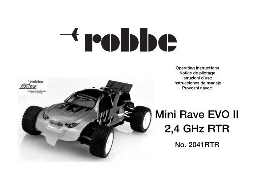
<strong>Mini</strong> <strong>Rave</strong> <strong>EVO</strong> <strong>II</strong><br />
2,4 <strong>GHz</strong> <strong>RTR</strong><br />
No. 2041<strong>RTR</strong>
Specification<br />
Length: approx. 255 mm<br />
Width: approx. 180 mm<br />
Wheelbase: approx. 175 mm<br />
Weight: approx. 600 g<br />
Scale: 1 : 18<br />
Dear customer,<br />
Congratulations on your choice of a factory-assembled electricpowered<br />
model vehicle from the robbe Modellsport range.<br />
Please take the trouble to read right through these instructions<br />
before you attempt to run the car for the first time. This will ensure<br />
that the model operates reliably and safely.<br />
All directions are as seen from the rear of the vehicle, looking forward.<br />
Essential accessories Order No.<br />
Non-rechargeable AA-size cell 8008<br />
Eight cells for transmitter<br />
Alternative items for rechargeable operation<br />
1.2 V NiMH cell 8005<br />
Eight cells for transmitter<br />
Unicharger 6 8500<br />
Transmitter charge lead F 1415<br />
Read and observe the instructions supplied with the charger and<br />
the batteries before using them.<br />
Operating instructions<br />
Please refer to these instructions constantly when preparing the<br />
model for running.<br />
Notes: to avoid injury please take particular care when handling<br />
tools and the model’s components.<br />
Please check that all screws are tight, and re-tighten them if necessary.<br />
We recommend that you store these instructions in a safe place, so<br />
that you can refer to them if you ever need to carry out repairs or<br />
order replacement parts.<br />
Please turn to page 9 for additional information regarding the radio<br />
control system.<br />
You will find an overall view of the car’s components on pages 10<br />
and 11.<br />
© robbe Modellsport<br />
<strong>Mini</strong> <strong>Rave</strong> <strong>EVO</strong> <strong>II</strong> 2,4 <strong>GHz</strong> <strong>RTR</strong><br />
Figs. 1 and 2, inserting the dry / rechargeable cells in the transmitter<br />
- Open the battery compartment by sliding the bottom panel of the<br />
transmitter to the rear.<br />
- Insert the dry / rechargeable cells, taking care to maintain correct<br />
polarity.<br />
- Close the battery compartment again.<br />
Notes regarding dry cells:<br />
- Do not attempt to recharge dry cells, do not open them, and do<br />
not incinerate them. Remove exhausted dry cells from the transmitter<br />
immediately, as any escaping electrolyte will damage and<br />
possibly ruin the transmitter.<br />
- Take exhausted dry cells to your local battery collection point for<br />
proper disposal.<br />
Fig. 3 and 4, the controls on the front of the transmitter<br />
- A: Steering wheel<br />
- B: Throttle trigger (forward / reverse)<br />
- C: Steering trim<br />
- D: Throttle trim (forward / reverse)<br />
- E: Taster für Empfänger-Anbindung<br />
- F: Charge socket<br />
- G: Reverse (servo reverse), steering<br />
- H: Reverse (servo reverse), throttle<br />
- I: Channel 3 (switched channel)<br />
- J: Servo travel, steering +<br />
- K: Servo travel, steering -<br />
- L: Steering trim indicator (row of LEDs)<br />
- M: Throttle trim indicator (row of LEDs)<br />
- N: On / Off switch<br />
- 0: Power indicator<br />
- P: Operating mode indicator<br />
Power indicator<br />
- The transmitter is ready for use when the red LED “O” glows constantly.<br />
If the red LED flashes, cease operations and recharge the<br />
battery cells / fit new dry cells.<br />
Alternative power source: rechargeable transmitter cells<br />
Fig. 5<br />
Note: If you are using rechargeable cells for the transmitter, give<br />
them a full charge at this point. Read the instructions supplied with<br />
the battery charger.<br />
- F: Charge socket<br />
Operating instructions<br />
2<br />
Fig. 6, the RC components in the model<br />
- Q: Electronic speed controller<br />
- R: Steering servo<br />
- S: Receiver<br />
- T: On / Off switch<br />
- U: Electric motor<br />
- V: Battery compartment with drive battery<br />
- Note re. switch “T”: the button in front of the switch can be used<br />
to adjust the “full-throttle”, “stop” and “reverse” throttle positions.<br />
These are pre-set at the factory, and should not be altered.<br />
The following description just serves to explain this function:<br />
- Switch the transmitter on. The button now has to be held pressed<br />
in for about three seconds while you switch the receiver on;<br />
switch the receiver on.<br />
- Move the throttle lever to the “full-throttle” position and hold it<br />
there until you hear a beep to confirm the setting.<br />
- Move the throttle lever to the “stop” setting and hold it in that<br />
position until you hear a double beep.<br />
- Move the throttle lever to the “reverse” position, and hold it there<br />
until you hear a triple beep.<br />
- Switch the receiver off to conclude the adjustment procedure.<br />
Fig. 7 and 8<br />
- Thread the flexible wire aerial attached to the receiver into the<br />
plastic aerial sleeve.<br />
- Push the bottom of the aerial sleeve into the aerial base.<br />
- Fit the cap to seal the top end of the aerial sleeve.<br />
Fig. 9<br />
- Remove the split pins, remove the battery retainer cross-piece<br />
and lift out the rechargeable drive battery.<br />
Fig. 10, charging the drive battery<br />
No.<br />
2041<strong>RTR</strong><br />
- Connect the battery charger to the mains supply (220 V).<br />
- Connect the battery.<br />
- A full charge (flat battery) takes about three hours.<br />
- Disconnect the drive battery from the charger when the charge<br />
period has elapsed. Disconnect the charger from the mains.<br />
- Caution: the charger is not fitted with an automatic charge cutoff<br />
circuit. For this reason it is essential to monitor the charge<br />
process, and terminate the charge when the drive battery is<br />
warm to the touch.
Safety notes<br />
- Do not leave the charger and the battery on an inflammable surface<br />
when charging is in progress. Do not leave batteries on<br />
charge unsupervised.<br />
- Protect the charger and drive battery from damp.<br />
- Do not subject the battery or charger to direct sunshine. Do not<br />
cover the charger.<br />
- Use only drive batteries which are specifically stated to be “fastcharge<br />
capable”.<br />
- Do not recharge any battery which is hot to the touch. Allow the<br />
pack to cool down to ambient temperature before recharging.<br />
- Observe the limits stated by the battery manufacturer.<br />
- The battery must only be charged with the supplied charger,<br />
do not use any other type of charger.<br />
- The charger should only be used to recharge the battery supplied<br />
in the model set.<br />
Figs. 11 and 12<br />
- Place the drive battery in the battery compartment, fit the crosspiece,<br />
and secure it with the split pins.<br />
- Switch the transmitter on.<br />
- Connect the drive battery. Switch the receiving system on. Wait<br />
for the speed controller to emit a series of beeps.<br />
- The system is switched off by reversing the sequence described<br />
above.<br />
Figs. 13 and 14, the steering system<br />
- Move the steering wheel “A” to the right (left), and the front<br />
wheels should also deflect to the right (left).<br />
- If the wheels move the wrong way, operate the servo reverse<br />
switch “G”.<br />
Figs. 15 and 16, throttle (forward / reverse)<br />
- If you move the throttle stick “B” in the forward direction “V”, the<br />
model should move forward. If it runs in reverse, operate the<br />
servo reverse switch “H” for the throttle channel.<br />
In order to avoid premature gearbox wear, it is not possible to<br />
switch directly from forward to reverse running. If you wish to<br />
switch from forward to reverse, slow the car with the brake before<br />
moving the throttle briefly to the neutral position. Only then is<br />
it possible to run the car in reverse.<br />
© robbe Modellsport<br />
Chassis settings:<br />
<strong>Mini</strong> <strong>Rave</strong> <strong>EVO</strong> <strong>II</strong> 2,4 <strong>GHz</strong> <strong>RTR</strong><br />
- Note: the chassis is set up accurately at the factory. Once you<br />
have become familiar with the model’s running characteristics<br />
and handling, you can fine-tune it to suit your personal preferences<br />
by adjusting the chassis.<br />
Figs. 17 and 18, adjusting the shock absorbers:<br />
- Please note that all the following adjustments must always be<br />
carried out on both sides of the axle, otherwise you will not<br />
obtain the desired results.<br />
- You can adjust the ground clearance and spring tension by rotating<br />
the knurled nut on the shock absorber cylinder. The setting<br />
for ground clearance should be adjusted to suit the type of surface<br />
over which you wish to run the model. The basic rule is this:<br />
always keep clearance as low as possible, whilst avoiding the<br />
chassis striking the ground at the extremes of spring travel.<br />
- The suspension characteristics can be altered by changing the<br />
attachment point of the shock absorbers. As supplied, the<br />
model’s shock absorbers are fitted in such a way that the car<br />
handles well on a relatively even surface. This is generally known<br />
as a “hard” shock absorber setting.<br />
- Fitting the shock absorbers at a shallower angle produces a softer<br />
shock absorber setting which is more suitable for uneven terrain.<br />
Fig. 19, adjusting toe-in:<br />
- The toe-in setting on the front axle affects the model’s straightrunning<br />
characteristics and the sensitivity of the steering. If you<br />
set positive toe-in (diagram 1), the car will be very stable when<br />
running straight, but respond relatively slowly to steering commands.<br />
If you set toe-out (diagram 2) the car will track less well,<br />
but will be more sensitive to steering commands. In the default<br />
setting the car is set up with virtually neutral toe-in (diagram 3)<br />
which gives good straight-running characteristics and normal<br />
steering response. Changes to this setting should only be made<br />
in small increments.<br />
Fig. 20, adjusting camber:<br />
Operating instructions<br />
- Normally the camber of the wheels on both axles is set in such a<br />
way that the full width of the tyres makes contact with the ground<br />
(default setting). If you shorten the upper (adjustable) transverse<br />
arms it is possible to set negative camber on that axle,<br />
which results in higher traction when turning, since the vehicle<br />
“resists the turn” better. However, the disadvantage of this setting<br />
is that the tyres tend to wear unevenly, and will also wear out<br />
more quickly due to the smaller contact area. At the other extre-<br />
3<br />
me, positive camber results in reduced traction on that axle. For<br />
most off-road models the recommended setting is usually neutral<br />
or a slightly negative camber angle.<br />
- The basic rule is that any changes to the chassis should only be<br />
made in small steps, followed by extensive track testing in order<br />
to evaluate the results.<br />
Figs. 21 and 22<br />
" Adjusting the differential "<br />
1.Front differential: left adjuster screw<br />
2. Rear differential: right adjuster screw<br />
3. Forward<br />
4. Front<br />
5. Rear<br />
+ = harder differential<br />
- = softer differential<br />
6. Allen key: 1.5 mm<br />
Binding the transmitter and receiver<br />
2.4 <strong>GHz</strong> transmitters and receivers have to be “bound” to each<br />
other before use, but this process has already been carried out at<br />
the factory. The procedure only needs to be repeated if the system<br />
is repaired, or if a component is changed.<br />
Figs. 23 - 26<br />
- Insert the rechargeable battery and connect it.<br />
- Receiver: withdraw the steering servo lead - “Channel 1, Bind” -<br />
from the receiver, and fit the jumper (bridging plug) in its place.<br />
- Transmitter: press the bind button “E”, and only then switch the<br />
transmitter on. The green LED flashes - see arrow.<br />
- Switch the receiving system on: the green LED in the receiver<br />
case flashes.<br />
- If the binding procedure is successful, the receiver LED stops<br />
flashing and glows continuously.<br />
- Switch off the receiving system and transmitter. Withdraw the<br />
jumper and plug in the steering servo again.<br />
- Switch the transmitter on, followed by the receiver. A triple beep<br />
indicates that the system is ready for use.<br />
robbe Modellsport GmbH & Co. KG<br />
We reserve the right to alter technical specifications.<br />
No.<br />
2041<strong>RTR</strong>
Replacement Parts List<br />
Order No. Description<br />
20410001 Servo-saver, complete<br />
20410002 Steering pushrod<br />
20410003 Servo pushrod<br />
20410004 Rear diff. housing, complete<br />
20410005 Front diff. housing, complete<br />
20410006 Tyre set<br />
20410007 Drive shaft<br />
20410008 Differential, complete<br />
20410009 Shock absorber<br />
20410010 Steering link<br />
20410011 Gearbox guard plate<br />
20410012 Rear shock absorber bracket<br />
20410013 Front shock absorber bracket<br />
20410014 Front upper transverse arm<br />
20410015 Front lower transverse arm<br />
20410016 Rear upper transverse arm<br />
20410017 Rear lower transverse arm<br />
20410018 Front stub axle<br />
20410019 Rear stub axle<br />
20410020 Main gear<br />
20410021 Wheel driver set<br />
20410022 Drive shaft support<br />
20410023 Front ram<br />
20410024 Rear transverse arm bracket<br />
20410025 Centre brace<br />
20410026 Main drive shaft end-piece<br />
20410027 Servo mount<br />
20410028 Servo output arm set<br />
20410029 Ball-link set<br />
20410030 Chassis<br />
20410031 Lower gearbox guard plate<br />
20410032 Bellcrank support<br />
20410033 Ball-links<br />
20410034 Axles<br />
20410035 Transverse arm pins<br />
20410036 Main drive shaft<br />
20410037 Stub axle joint ball<br />
20410038 Servo lever ball<br />
20410039 Differential sleeves<br />
20410040 Ball-end bolt<br />
20410041 Motor pinion, 14-tooth<br />
20410042 Motor mount<br />
20410043 Wheel nut<br />
20410044 Speed controller<br />
20410045 Motor<br />
20410046 Aerial sleeve and cap<br />
20410047 Body shell, red<br />
20410048 Body shell, white<br />
20410049 Ballrace set<br />
© robbe Modellsport<br />
<strong>Mini</strong> <strong>Rave</strong> <strong>EVO</strong> <strong>II</strong> 2,4 <strong>GHz</strong> <strong>RTR</strong><br />
Order No. Description<br />
20410050 Screw set<br />
20370020 Wheel axles<br />
20370023 Axle spring<br />
20370036 Battery holder<br />
20370037 Body shell clip<br />
20370042 Motor heat-sink<br />
Service Centre Addresses<br />
Operating instructions<br />
robbe Modellsport GmbH & Co. KG hereby declares that this product satisfies<br />
the fundamental requirements and other relevant regulations contained<br />
in the appropriate CE directives. The original Conformity Declaration can be<br />
viewed on the Internet under www.robbe.com: click on the logo button marked<br />
“Conform” which is included in each device description.<br />
4<br />
No.<br />
2041<strong>RTR</strong><br />
Country Company Street Town Telephone Fax E-Mail<br />
AND-00130 Les escaldes-<br />
Andorra Sorteney Santa Anna, 13<br />
Princip. D'Andorre 00376-862 865 00376-825 476 sorteny@sorteny.com<br />
Denmark Nordic Hobby A/S Bogensevej 13 DK-8940 Randers SV 0045-86-43 61 00 0045-86-43 77 44 hobby@nordichobby.com<br />
Germany robbe-Service Metzloser Str. 38 D-36355 Grebenhain 0049-6644-87-777 0049-6644-87-779 hotline@robbe.com<br />
England robbe-Schlüter UK LE10-UB GB-LE10 3DS Leicestershire 0044-1455-637151 0044-1455-635151 keith@robbeuk.co.uk<br />
France S.A.V Messe 6, Rue Usson du Poitou, BP 12 F-57730 Folschviller 0033 3 87 94 62 58 0033-3-87 94 62 58 sav-robbe@wanadoo.fr<br />
Greece TAG Models Hellas 18,Vriullon Str. GR-14341 New Philadelfia/Athen 0030-2-102584380 0030-2-102533533 info@tagmodels.gr<br />
I-36010 Cavazzale<br />
Italy MC-Electronic Via del Progresso, 25<br />
di Monticello C.Otto (Vi) 0039 0444 945992 0039 0444 945991 mcelec@libero.it<br />
Netherl. / Belgium Jan van Mouwerik Slot de Houvelaan 30 NL-3155 Maasland 0031-10-59 13 594 0031-10-59 13 594 van_Mouwerik@versatel.nl<br />
Norway Norwegian Modellers Box 2140 N-3103 Toensberg 0047-333 78 000 0047-333 78 001 per@modellers.com<br />
Austria robbe-Service Puchgasse 1 A-1220 Wien 0043-1259-66-52 0043-1258-11-79 office@robbe.at<br />
Sweden <strong>Mini</strong>cars Hobby A.B. Bergsbrunnagatan 18 S-75323 Uppsala 0046-186 06 571 0046-186 06 579 info@minicars.se<br />
Switzerland Servicecenter Hässig Baslerstrasse 67 a CH-4203 Grellingen 0041-61-741 23 22 0041-61 741 23 34 info@robbefutaba-service.ch<br />
Slovak Rep. Ivo Marhoun Horova 9 CZ-35201 AS 00420 351 120 162 ivm2000@seznam.cz<br />
Spain robbe-Service Metzloser Str. 38 D-36355 Grebenhain 0049-6644-87-777 0049-6644-87-779 hotline@robbe.com<br />
Czech Rep. Ivo Marhoun Horova 9 CZ-35201 AS 00420 351 120 162 ivm2000@seznam.cz<br />
This symbol means that you must dispose of electrical and electronic equipment<br />
separately from the general household waste when it reaches the end<br />
of its useful life.<br />
Take your equipment to your local waste collection point or recycling<br />
centre. This applies to all countries of the European Union, and<br />
to other European countries with a separate waste collection<br />
system.<br />
Errors and omissions excepted. Modifications reserved.<br />
Copyright robbe-Modellsport 2010<br />
Copying and re-printing, in whole or in part, only with prior written approval of robbe-Modellsport GmbH & Co. KG
Caractéristiques techniques<br />
longueur: approx. 255 mm<br />
largeur : approx. 180 mm<br />
empattement : approx. 175 mm<br />
Poids : approx. 600 g<br />
Échelle : 1:18<br />
Cher Client,<br />
Vous avez choisi une auto, avec moteur électrique, entièrement<br />
assemblée de la Sté robbe modellsport.<br />
Afin d'exploiter aux mieux les possibilités de ce modèle et de le<br />
faire évoluer en toute sécurité, nous vous recommandons la lecture<br />
attentive de la présente notice et des informations jointes avant<br />
d'effectuer votre première sortie.<br />
Les indications directionnelles sont à considérer dans le sens du<br />
déplacement de l'auto.<br />
Accessoires nécessaires à la mise en œuvre du modèle<br />
Réf.<br />
pile de type R6 (non rechargeable) 8008<br />
8x pour l'émetteur<br />
alternativement, une alimentation par accu rechargeable<br />
élément NiMH 1,2 volts 8005<br />
8x pour l'émetteur<br />
chargeur Unicharger 6 8500<br />
cordon de charge de l'émetteur F 1415<br />
Avant d'effectuer une charge, lire attentivement les instructions<br />
fournies par la notice du chargeur et du fabricant de l'accu.<br />
Notice de montage et instructions de service<br />
Pour la préparation du modèle, tenir compte des instructions fournies<br />
par la présente notice.<br />
À noter : pour éviter toute blessure, il est particulièrement recommandé<br />
de manipuler les outils nécessaires et les composants du<br />
modèle avec précaution.<br />
Vérifier la bonne assise de toutes les vis et les resserrer si nécessaire.<br />
Il est recommandé de conserver la notice afin de pouvoir la consulter<br />
pour les réparations éventuelles et la commande de pièces<br />
de rechange.<br />
© robbe Modellsport<br />
Notice de pilotage<br />
<strong>Mini</strong> <strong>Rave</strong> <strong>EVO</strong> <strong>II</strong> 2,4 <strong>GHz</strong> <strong>RTR</strong><br />
Consignes complémentaires concernant l'ensemble de radiocommande,<br />
Cf. page 9.<br />
Un récapitulatif des pièces de rechange est présenté sur les pages<br />
10 et 11.<br />
Fig. 1 et 2, mise en place des piles / accus dans l'émetteur<br />
- Ouvrir le logement des piles, glisser le fond de l'émetteur vers<br />
l'arrière.<br />
- Mettre les piles / les accus en place en tenant compte des polarités<br />
indiquées.<br />
- Refermer le logement de l'alimentation électrique.<br />
Remarques concernant les piles sèches :<br />
- Les piles ne sont pas rechargeables, ne pas ouvrir, ne pas jeter<br />
dans un feu. Lorsque les piles sont déchargées, les retirer de l'émetteur.<br />
Si le liquide électrolytique s'échappe, il risque de provoquer<br />
des dommages dans l'émetteur.<br />
- Mettre les piles au rebut à un point de collecte spécialisé.<br />
Fig. 3 et 4, les éléments de commande en façade de l'émetteur<br />
- A : volant<br />
- B : manche des gaz (marche avant / marche arrière)<br />
- C : dispositif de réglage de précision (trim) de la direction<br />
- D : dispositif de réglage de précision (trim) des gaz (marche<br />
avant / marche arrière)<br />
- E : Bouton de liaison du récepteur<br />
- F : Douille de charge<br />
- G : Reverse (inversion de la course du servo) direction<br />
- H : Reverse (inversion de la course du servo) gaz<br />
- I : voie 3 (voie de commutation)<br />
- J : course du servo direction +<br />
- K : course du servo direction -<br />
- L : Affichage du réglage de précision (trim) de la direction<br />
(rangée de diodes)<br />
- M : Affichage du réglage de précision (trim) des gaz (rangée de<br />
diodes)<br />
- N : Interrupteur Marche/Arrêt<br />
- O : Indications concernant le fonctionnement<br />
- P : Affichage d'état du mode opératoire<br />
Indications concernant le fonctionnement<br />
- Lorsque la diode rouge “O” est allumée, l'émetteur est en ordre<br />
de marche. Lorsque la diode rouge clignote, stoppez immédiatement<br />
la séance de pilotage, chargez les éléments d'accu ou remplacez<br />
les piles.<br />
5<br />
Utilisation alternative d'accus d'émetteurs<br />
Fig. 5<br />
À noter : Charger les accus de l’émetteur avant la mise en service.<br />
Tenir compte des indications fournies par la notice du chargeur.<br />
- F : Douille de charge<br />
Fig. 6, les composants de l'ensemble de radiocommande dans le<br />
modèle<br />
- Q: variateur de vitesse électronique<br />
- R: servo de direction<br />
- S : récepteur<br />
- T : Interrupteur Marche/Arrêt<br />
- U : Moteur électrique<br />
- V : logement de l'accu avec accu d'alimentation du moteur<br />
- Instructions concernant l'interrupteur “T” : Le bouton devant<br />
l'interrupteur sert à mettre au point les positions des gaz “plein<br />
gaz”, “arrêt” et “marche arrière”. Celles-ci sont déterminées à<br />
l'usine et ne devraient en aucun cas être changées.<br />
La description du bouton est simplement utile à l'explication<br />
de la fonction.<br />
- Mettez l'émetteur en marche, maintenez le bouton enfoncé pendant<br />
approx. 3 secondes pendant la mise en marche du récepteur,<br />
mettez le récepteur en marche.<br />
- Amenez le manche de gaz en position plein gaz jusqu'à ce qu'un<br />
bip de validation retentisse.<br />
- Amenez le manche des gaz en position arrêt et le maintenir dans<br />
cette position jusqu'à ce qu'un double bip retentisse.<br />
- Amenez le manche des gaz en position marche arrière et le maintenir<br />
dans cette position jusqu'à ce qu'un triple bip retentisse.<br />
- Coupez le récepteur, la mise au point est terminée.<br />
Fig. 7 et 8<br />
- Enfiler l'antenne souple du récepteur dans le tube d'antenne.<br />
- Planter le tube d'antenne dans le pied de l'antenne.<br />
- Bouchez le tube en haut à l'aide du capuchon.<br />
Fig. 9<br />
- Desserrer la goupille, retirer la traverse, retirer l'accu.<br />
réf.<br />
2041<strong>RTR</strong><br />
Fig. 10, charger l'accu d'alimentation du moteur<br />
- Raccorder le chargeur au secteur (220 V).<br />
- Raccorder l’accu.<br />
- La durée de charge de l'accu vide est de 3 heures approximativement.<br />
- Une fois la charge de l'accu achevée, désolidariser l'accu du<br />
chargeur. Désolidariser le chargeur de la prise du secteur.<br />
- Attention : le chargeur ne s'arrête pas automatiquement en fin<br />
de charge. Il est de ce fait indispensable de surveiller la procédure<br />
de charge et de l'interrompre si la chaleur de l'accu augmente.
Consignes de sécurité<br />
- Ne pas faire fonctionner le chargeur et ne pas poser l'accu sur<br />
une surface inflammable et ne pas les laisser sans surveillance<br />
pendant la charge.<br />
- Protéger de l'humidité.<br />
- Ne pas les exposer directement au rayons du soleil, ne pas couvrir<br />
le chargeur.<br />
- N'utiliser que des accus susceptibles de recevoir une charge<br />
rapide.<br />
- Ne pas charger d'accus chauds. Laisser refroidir les accus à<br />
température ambiante.<br />
- Tenir compte des instructions fournies par le fabricant de l'accu.<br />
- Ne chargez l'accu qu'avec le chargeur contenu dans le kit, n'utilisez<br />
aucun autre chargeur.<br />
- N'utiliser le chargeur que pour les accus fournis avec le kit du<br />
modèle.<br />
Fig. 11 et 12<br />
- Installer l'accu dans le logement et le fixer avec la traverse et les<br />
goupilles.<br />
- Mettre l'émetteur en marche.<br />
- Raccorder l’accu d’alimentation du moteur. Mettre l'ensemble de<br />
réception en marche. Attendre la séquence des sons du variateur.<br />
- Pour couper l'ensemble de réception procéder dans l’ordre<br />
inverse.<br />
Fig. 13 et 14, la direction<br />
- Lorsque vous actionnez le volant “A“ vers la droite (gauche) il<br />
faut que les roues présentent un débattement vers la droite (gauche).<br />
- Si ce n'est pas le cas, actionnez l'interrupteur d'inversion de la<br />
course du servo „G“.<br />
Fig. 15 et 16, gaz (marche avant et marche arrière)<br />
- Lorsque le manche des gaz “B” est déplacé en direction marche<br />
avant “V”, il faut que le modèle entreprenne de se mouvoir vers<br />
l'avant. Si ce n'est pas le cas, actionnez le dispositif d'inversion<br />
de la course du servo „H“ de la voie des gaz dans l'émetteur.<br />
- Pour épargner le mécanisme il n'est pas possible de passer<br />
directement de marche avant sur marche arrière. Pour passer de<br />
marche avant en marche arrière, freinez le modèle,<br />
- Amenez les gaz brièvement en position neutre. Il n'est possible<br />
qu'ensuite de passer en marche arrière.<br />
© robbe Modellsport<br />
Notice de pilotage<br />
<strong>Mini</strong> <strong>Rave</strong> <strong>EVO</strong> <strong>II</strong> 2,4 <strong>GHz</strong> <strong>RTR</strong><br />
Mises au point des roues :<br />
- À noter : Le châssis a été réglé en usine. Lorsque vous vous êtes<br />
familiarisé avec le modèle, il est possible de l'ajuster à vous habitudes<br />
de pilotage en modifiant des réglages des roues.<br />
Fig. 17 et 18, régler les amortisseurs :<br />
- Notez que tous les réglages décrits ci-dessous doivent être<br />
appliqués des deux côtés de l'essieu pour obtenir l'effet désiré.<br />
- Le fait de tourner l'écrou moleté sur le vérin de l'amortisseur permet<br />
de modifier la garde au sol et la précontrainte du ressort. Le<br />
réglage de la garde au sol doit être réalisé en fonction de la nature<br />
du sol sur lequel la voiture est destinée à rouler et doit toujours<br />
être maintenue aussi petite que possible sans que le châssis risque<br />
de toucher le sol en bout de course d'amortissement.<br />
- La caractéristique d'amortissement peut être modifiée en changeant<br />
l'angle de fixation des amortisseurs.<br />
- Pour la livraison, les amortisseurs du modèle sont montés de<br />
telle sorte que les caractéristiques de pilotage soient celles qui<br />
correspondent à un sol relativement plan. Il s'agit alors d'un<br />
amortissement relativement dur.<br />
- Si on monte les amortisseurs de manière plus plate, le comportement<br />
à l'amortissement est plus souple et particulièrement<br />
approprié à des pistes au revêtement déformé.<br />
Fig. 19, réglage du pinçage :<br />
- Le réglage de la voie de l'essieu avant a une incidence sur le<br />
roulement rectiligne du modèle et la sensibilité de la direction.<br />
Avec un pinçage positif (représentation schématique 1) le véhicule<br />
présente un roulement calme et rectiligne et réagit avec une<br />
certaine réserve aux mouvements de la direction. Avec un pinçage<br />
négatif (représentation schématique 2) la stabilité directionnelle<br />
est moins bonne et le modèle réagit de manière plus<br />
sensible aux instructions directionnelles. À la livraison, le modèle<br />
est réglé pour une bonne stabilité directionnelle et un comportement<br />
normal à la direction avec un pinçage pratiquement neutre<br />
des roues avant (représentation schématique 3). Effectuer les<br />
modifications qui s'imposent avec une certaine retenue.<br />
Fig. 20, réglage du carrossage :<br />
- Normalement, le carrossage des roues de l'un des essieux est<br />
établi de telle manière que les pneumatiques prennent appui au<br />
sol sur toute la surface (comme c'est le cas sur le modèle à la<br />
livraison). Lorsqu'on raccourcit le bras d'oscillation réglable du<br />
haut, on obtient un carrossage négatif de l'essieu. Ceci provoque<br />
une traction plus importante dans les virages étant donné que le<br />
véhicule se „couche dans le virage“ mais a pour inconvénient<br />
que les pneumatiques ne s'usent pas régulièrement et s'usent<br />
plus rapidement à cause de la surface de roulement réduite. Un<br />
6<br />
carrossage positif réduit la traction sur l'essieu. Sur un modèle<br />
tout terrain, il est recommandé d'établir un carrossage neutre ou<br />
légèrement négatif.<br />
- En principe, n'appliquer les modifications sur les roues que par<br />
étapes avant de tester ensuite longtemps sur la piste.<br />
Fig. 21 and 22<br />
Mise au point des différentiels<br />
1.Différentiel avant : vis de mise au point gauche<br />
2. Différentiel arrière : vis de mise au point droite<br />
3. Sens du déplacement<br />
4. Avant<br />
5. Arrière<br />
+ = différentiel plus dur<br />
- = différentiel plus souple<br />
6. Clé six pans : 1,5 mm<br />
Liaison de l'émetteur et du récepteur<br />
La liaison indispensable de l'émetteur et du récepteur avec le<br />
système 2,4 <strong>GHz</strong> a déjà été réalisée en usine. Il n'est nécessaire<br />
de rétablir la liaison qu'après une réparation ou un remplacement.<br />
Fig. 23 à 26<br />
- Installez l’accu d'alimentation du moteur et raccordez-le.<br />
- Récepteur : Retirez le cordon du servo de direction - “Channel 1,<br />
Bind” - du récepteur et mettez le cavalier (shunt) en place.<br />
- Émetteur : Pressez le bouton de liaison “E” et ne mettez l'émetteur<br />
en marche qu'ensuite. La diode verte clignote - Cf. flèche.<br />
- Mettre l’ensemble de réception en place. La diode verte dans le<br />
boîtier du récepteur clignote.<br />
- Lorsque la liaison est établie, la diode du récepteur reste allumée<br />
en permanence.<br />
- Coupez le récepteur puis l’émetteur. Extrayez le cavalier et raccordez<br />
à nouveau le servo de direction.<br />
- Mettez l'émetteur en marche, mettez le récepteur en marche. Un<br />
triple signal sonore signale l'état de marche.<br />
robbe Modellsport GmbH & Co. KG<br />
Sous réserve de modification technique<br />
réf.<br />
2041<strong>RTR</strong>
Liste des pièces de rechange<br />
réf. Désignation<br />
20410001 Sauve-servo complet<br />
20410002 Tringle de direction<br />
20410003 Tringle de servo<br />
20410004 Carter de différentiel complet arrière<br />
20410005 Carter de différentiel complet avant<br />
20410006 Jeu de pneumatiques<br />
20410007 Transmission<br />
20410008 Différentiel complet<br />
20410009 Amortisseur<br />
20410010 Liaison de direction<br />
20410011 Plaque de protection du mécanisme<br />
20410012 Support d'amortisseur arrière<br />
20410013 Support d'amortisseur avant<br />
20410014 Bras oscillant avant en haut<br />
20410015 Bras oscillant avant en bas<br />
20410016 Bras oscillant arrière en haut<br />
20410017 Bras oscillant arrière en bas<br />
20410018 Fusée d'essieu avant<br />
20410019 Fusée d'essieu arrière<br />
20410020 Couronne principale<br />
20410021 Jeu d'entraîneurs de roue<br />
20410022 Support arbre d'entraînement<br />
20410023 Bouclier de protection avant<br />
20410024 Porte-bras oscillant transversal arrière<br />
20410025 Étai central<br />
20410026 Embout d'arbre d'entraînement principal<br />
20410027 Support-servo<br />
20410028 Jeu de palonniers de servo<br />
20410029 Jeu de pivots sphériques<br />
20410030 Châssis<br />
20410031 Plaques de protection du mécanisme du bas<br />
20410032 Support palonnier de renvoi<br />
20410033 Biellettes<br />
20410034 Arbres d'essieu<br />
20410035 Goupilles de bras d'oscillation transversal<br />
20410036 Arbre d'entraînement principal<br />
20410037 Rotule de fusée d'essieu<br />
20410038 Pivot sphérique de servo<br />
20410039 Manchon de différentiel<br />
20410040 Boulon à rotule<br />
20410041 Pignon 14 dents du moteur<br />
20410042 Support-moteur<br />
20410043 Écrou de roue<br />
20410044 Variateur<br />
20410045 Moteur<br />
20410046 Tube d'antenne avec capuchon<br />
20410047 Carrosserie rouge<br />
20410048 Carrosserie blanche<br />
20410049 Jeu de roulements<br />
© robbe Modellsport<br />
<strong>Mini</strong> <strong>Rave</strong> <strong>EVO</strong> <strong>II</strong> 2,4 <strong>GHz</strong> <strong>RTR</strong><br />
réf. Désignation<br />
Notice de pilotage<br />
20410050 Jeu de vis<br />
20370020 Axes de roue<br />
20370023 Ressort d'arbre d'essieu<br />
20370036 Porte-accu<br />
20370037 Goupille de carrosserie<br />
20370042 Culasse de refroidissement du moteur<br />
Adresse des ateliers du service après-vente<br />
Par la présente la Sté robbe Modellsport GmbH & Co. KG, déclare que cet<br />
appareil répond aux exigences fondamentales et à d’autres prescriptions<br />
significatives de la directive appropriée de la Communauté européenne.<br />
L’original de la déclaration de conformité se trouve dans l’Internet sur le site<br />
www.robbe.com associée à la description de l’appareil concerné et apparaît<br />
lorsqu’on clique le bouton portant le logo "Conform".<br />
7<br />
réf.<br />
2041<strong>RTR</strong><br />
Pays Société rue ville Téléphone télécopie E-Mail<br />
AND-00130 Les escaldes-<br />
Andorre Sorteney Santa Anna, 13<br />
Princip. D'Andorre 00376-862 865 00376-825 476 sorteny@sorteny.com<br />
Danemark Nordic Hobby A/S Bogensevej 13 DK-8940 Randers SV 0045-86-43 61 00 0045-86-43 77 44 hobby@nordichobby.com<br />
Allemagne robbe-Service Metzloser Str. 38 D-36355 Grebenhain 0049-6644-87-777 0049-6644-87-779 hotline@robbe.com<br />
Angleterre robbe-Schlüter UK LE10-UB GB-LE10 3DS Leicestershire 0044-1455-637151 0044-1455-635151 keith@robbeuk.co.uk<br />
France S.A.V Messe 6, Rue Usson du Poitou, BP 12 F-57730 Folschviller 0033 3 87 94 62 58 0033-3-87 94 62 58 sav-robbe@wanadoo.fr<br />
Grèce TAG Models Hellas 18,Vriullon Str. GR-14341 New Philadelfia/Athen 0030-2-102584380 0030-2-102533533 info@tagmodels.gr<br />
I-36010 Cavazzale<br />
Italie MC-Electronic Via del Progresso, 25<br />
di Monticello C.Otto (Vi) 0039 0444 945992 0039 0444 945991 mcelec@libero.it<br />
Pays-Bas/Bel.. Jan van Mouwerik Slot de Houvelaan 30 NL-3155 Maasland 0031-10-59 13 594 0031-10-59 13 594 van_Mouwerik@versatel.nl<br />
Norvège Norwegian Modellers Box 2140 N-3103 Toensberg 0047-333 78 000 0047-333 78 001 per@modellers.com<br />
Autriche robbe-Service Puchgasse 1 A-1220 Wien 0043-1259-66-52 0043-1258-11-79 office@robbe.at<br />
Suède <strong>Mini</strong>cars Hobby A.B. Bergsbrunnagatan 18 S-75323 Uppsala 0046-186 06 571 0046-186 06 579 info@minicars.se<br />
Suisse Servicecenter Hässig Baslerstrasse 67 a CH-4203 Grellingen 0041-61-741 23 22 0041-61 741 23 34 info@robbefutaba-service.ch<br />
Rép. slovaque Ivo Marhoun Horova 9 CZ-35201 AS 00420 351 120 162 ivm2000@seznam.cz<br />
Espagne robbe-Service Metzloser Str. 38 D-36355 Grebenhain 0049-6644-87-777 0049-6644-87-779 hotline@robbe.com<br />
Rép. tchèque Ivo Marhoun Horova 9 CZ-35201 AS 00420 351 120 162 ivm2000@seznam.cz<br />
Ce symbole signifie que les petits appareils électriques et électroniques<br />
irréparables ou en fin de cycle d’exploitation doivent être mis<br />
au rebut non pas avec les ordures ménagères mais dans les déchetteries<br />
spécialisées.<br />
Portez-les dans les collecteurs communaux appropriés ou un centre<br />
de recyclage spécialisé. Cette remarque s’applique aux pays de<br />
la Communauté européenne et aux autres pays européens pourvus d’un<br />
système de collecte spécifique.<br />
Sous réserve de d’erreur et de modification technique.<br />
Copyright robbe-Modellsport 2010<br />
Copie et reproduction, même d’extraits, interdites sans autorisation écrite expresse de la Société robbe-Modellsport GmbH & Co. KG
Dati tecnici<br />
Lunghezza: 255 mm ca.<br />
Larghezza: 180 mm ca.<br />
Passo: 175 mm ca.<br />
Peso: 600 g ca.<br />
Scala: 1:18<br />
Gentile acquirente,<br />
La ringraziamo per aver scelto questo automodello eltrrico premontato,<br />
appartenente alla famiglia di modelli della robbe<br />
Modellsport.<br />
Al fine di semplificarle l’utilizzo, raccomandiamo tassativamente di<br />
leggere con la massima attenzione l’intero manuale per l’uso prima<br />
di utilizzare l’automodello per la prima volta,.<br />
Tutte le indicazioni riguardanti le posizioni (es: “destra) sono da<br />
intendersi rispetto alla direzione di marcia.<br />
Accessori consigliati: Art.N.<br />
Pile mignon (non ricaricaribili) 8008<br />
8x trasmittente<br />
in alternativa, per l’alimentazione mediante batteria ricaricabile<br />
Cella NiMH 1,2V 8005<br />
8x trasmittente<br />
Caricabatterie Unicharger 6 8500<br />
Cavo per ricarica batterie trasmittente F1415<br />
Durante le operazioni di ricarica consultare le istruzioni allegate alla<br />
batteria ed al caricatore.<br />
Istruzioni per l’uso<br />
Fare riferimento al presente manuale di istruzioni per rendere il<br />
modello pronto all’utilizzo.<br />
Avvertenze:al fine di evitare incidenti e lesioni, si raccomanda vivamente<br />
di maneggiare con cautela gli attrezzi di montaggio ed i<br />
componenti dell’automodello.<br />
Verificare il corretto serraggio di tutte le viti e stringerle qualora<br />
risulti necessario.<br />
Si consiglia di conservare il presente manuale come riferimento per<br />
eventuali riparazioni future o come elenco e codifica per le parti di<br />
ricambio.<br />
Consultare pagina 9 per le altre avvertenze riguardanti la trasmittente<br />
e la ricevente. Consultare le pagine 10 e 11 per conoscere<br />
l’elenco generale delle parti di ricambio.<br />
© robbe Modellsport<br />
Istruzioni d’uso<br />
<strong>Mini</strong> <strong>Rave</strong> <strong>EVO</strong> <strong>II</strong> 2,4 <strong>GHz</strong> <strong>RTR</strong><br />
Immagini 1 e 2, inserimento delle pile nella trasmittente<br />
- Aprire il vano batterie spingendo indietro la base della trasmittente.<br />
- Inserire le pile / batterie rispettando la corretta polarità<br />
- Richiudere il vano batterie.<br />
- Avvertenze riguardanti le pile a secco (non ricaricabili):<br />
- Non ricaricare le pile,non aprirle e non gettarle nel fuoco. Una<br />
volta scariche, rimuovere le pile dalla trasmittente; l’elettrolita<br />
fuoriuscito può danneggiare quest’ultima.<br />
- Smaltire le pile scariche soltanto presso gli appositi centri di raccolta.<br />
Immagine 3 e 4, i comandi disposti sul lato frontale della trasmittente<br />
- A: Volantino dello sterzo<br />
- B: Leva di comando del gas (grilletto avanti / indietro)<br />
- C: Trim (regolazione di precisione) per lo sterzo<br />
- D: Trim (regolazione di precisione) per il gas<br />
-- E: Tasto per il collegamento della trasmittente con la ricevente<br />
- F: Presa per la ricarica<br />
- G: Reverse (inversione della corsa del servo) sterzo<br />
- H: Reverse (inversione della corsa del servo) gas<br />
- I: Canale 3 (Canale non proporzionale)<br />
- H: Interruttore acceso / spento<br />
- J: Regolazione dell’escursione dello sterzo +<br />
- K: Regolazione dell’escursione dello sterzo -<br />
- L: Visualizzazione trim di comando del gas<br />
(Visualizzazione LED)<br />
- M: Visualizzazione trim di comando del gas<br />
(Visualizzazione LED)<br />
- N: Interruttore accensione/spegnimento<br />
- O: Spia di funzionamento<br />
- P: Spia di controllo funzionalità<br />
Spia di funzionamento<br />
- Se il LED rosso “O” si illumina, la trasmittente è pronta per l’uso;<br />
se esso invece lampeggia, interrompere immediatamente l’utilizzo<br />
e sostituire o ricaricare le batterie di alimentazione.<br />
Alimentazione alternativa attraverso batteria ricaricabile anziché pile<br />
Immagine 5<br />
Avvertenza: qualora si utilizzino batterie ricaricabili, caricarle prima<br />
dell’uso, consultando le istruzioni del caricabatteria.<br />
- F: presa per la ricarica<br />
8<br />
Immagine 6, i componenti RC nell’automodello<br />
- Q: Regolatore elettronico di velocità<br />
- R: Servo di comando dello sterzo<br />
- S: Ricevente<br />
- T: Interruttore accensione/spegnimento<br />
- U: Motore elettrico<br />
- V: Vano con batteria di alimentazione del modello<br />
n.<br />
2041<strong>RTR</strong><br />
- Avvertenze sull’interruttore “T”: il tasto davanti all’interruttore<br />
serve per l’impostazione delle posizioni: “gas al massimo” ,<br />
“stop” e “indietro”. Queste risultano pre-impostate in fabbrica e<br />
conseguentemente non dovrebbero essere modificate. La<br />
descrizione del tasto serve soltanto per illustrarne la funzione<br />
svolta.<br />
- Accendere la trasmittente mantenendo premuto il tasto per 3<br />
secondi ca. durante la fase di accensione della ricevente.<br />
Accendere la ricevente.<br />
- Portare il grilletto di comando del gas in posizione „gas al massimo“<br />
fino a quando non viene emesso un segnale acustico di<br />
conferma.<br />
- Portare il grilletto di comando del gas in posizione di stop ed<br />
attendere fino a quando non viene emesso un doppio segnale<br />
acustico di conferma.<br />
- Portare il grilletto di comando del gas indietro (retromarcia) ed<br />
attendere fino a quando non viene emesso un triplice segnale<br />
acustico di conferma.<br />
- La procedura di installazione è terminata: risulta ora possibile<br />
spegnere la ricevente.<br />
Immagine 7 e 8<br />
- infilare l’antenna ricevente.<br />
- Infilare il tubo porta-antenna nell’apposita base di sostegno.<br />
- Infilare il cappuccio sull’estremità dell’ antenna.<br />
Immagine 9<br />
- Sganciare la copiglia, rimuovere la staffa di tenuta ed estrarre la<br />
batteria.<br />
Immagine 10, ricarica della batteria di alimentazione dell’automodello<br />
- Collegare la spina del caricabatterie alla presa di corrente da 220<br />
V.<br />
- Collegare la batteria di alimentazione del modello al caricabatterie.<br />
- Per una batteria scarica, la ricarica ha una durata di 3 ore circa.<br />
- Terminata la ricarica, scollegare la batteria dal caricabatterie,<br />
Successivamente scollegare il caricabatterie dalla presa elettrica.<br />
- Attenzione: il caricabatterie non si spegne automaticamente al<br />
termine della ricarica. Di conseguenza è necessario mantenere<br />
sorvegliata la procedura di ricarica ed interrompere la procedura<br />
qualora la batteria si scaldi in maniera eccessiva.
Norme per la sicurezza<br />
- Non posizionare il caricabatteria e la batteria su superfici<br />
infiammabili e non lasciarli incustoditi durante le fasi di ricarica.<br />
- Proteggere il caricabatteria e la batteria dall’umidità.<br />
- Non porre l’apparecchio a diretto contatto con i raggi solari e non<br />
coprirlo.<br />
- Utilizzare solamente batterie ricaricabili idonee per ricariche di<br />
tipo rapido.<br />
- Non ricaricare batterie già calde. In questo caso lasciarle prima<br />
raffreddare sino a temperatura ambiente.<br />
- Rispettare le indicazioni fornite dal produttore della batteria<br />
- Per la ricarica della batteria, adoperare esclusivamente il caricabatterie<br />
fornito in dotazione.<br />
- Adoperare il caricabatterie esclusivamente con la batteria inclusa<br />
nella confezione del modello.<br />
Immagini 11 e 12<br />
- Inserire la batteria nell’alloggiamento ed assicurarla mediante la<br />
staffa e la copiglia di sicurezza.<br />
- Accendere prima la trasmittente.<br />
- Collegare la batteria di alimentazione del modello. Accendere la<br />
trasmittente. Attendere il segnale acustico di conferma.<br />
- Per lo spegnimento del modello procedere in ordine inverso.<br />
Immagini 13 e 14, lo sterzo<br />
- Le ruote devono spostarsi verso destra (sinistra) azionando il<br />
volantino di comando “A” verso destra (sinistra).<br />
- In caso contrario, azionare l’interruttore Servo-Reverse “G” per<br />
invertire i comandi.<br />
Immagini 15 e 16, gas (avanti/indietro)<br />
- Quando la leva di comando del gas “B” si trova in posizione<br />
avanti “V”, il modello deve spostarsi in avanti. Se questo non si<br />
verifica, è necessario azionare sulla trasmittente l’interruttore<br />
Servo Reverse “H” relativo al canale del gas.<br />
- Al fine di preservare il meccanismo di trasmissione, non risulta<br />
possibile effettuare un passaggio repentino da marcia avanti a<br />
marcia indietro. In tale circostanza occorre prima frenare il<br />
modello e lasciare per un istante la leva di comando del gas a<br />
metà corsa. Solamente in seguito sarà possibile azionare la<br />
retromarcia.<br />
Regolazioni dell’assetto del modello:<br />
- Avvertenza: il modello vene regolato inizialmente in fabbrica.<br />
Dopo aver familiarizzato con il pilotaggio e le reazioni del modello<br />
in configurazione base, potete agire sulle regolazioni di quest’ultimo<br />
per meglio adattarlo al vostro stile di guida.<br />
© robbe Modellsport<br />
Istruzioni d’uso<br />
<strong>Mini</strong> <strong>Rave</strong> <strong>EVO</strong> <strong>II</strong> 2,4 <strong>GHz</strong> <strong>RTR</strong><br />
Immagini 17 e 18, regolazione degli ammortizzatori<br />
- Le regolazioni seguenti devono essere effettuate su entrambi i<br />
lati dello stesso asse del modello al fine di ottenere gli effetti ad<br />
esse associati.<br />
- Ruotando la molla di precarico, situata sul cilindro degli ammortizzatori,<br />
è possibile variare l’altezza da terra del modello ed il<br />
carico delle molle . L’altezza da terra viene regolata in base al terreno<br />
su cui il modello viene utilizzato. E’ preferibile mantenerla<br />
sempre quanto più bassa possibile, facendo tuttavia attenzione<br />
affinché il telaio non tocchi il suolo mentre l’ammortizzatore è<br />
compresso.<br />
- Il modo più agevole per modificare il comportamento degli<br />
ammortizzatori, è quello di agire variando la loro posizione di fissaggio<br />
rispetto al veicolo.<br />
- La regolazione di base degli ammortizzatori,ovvero quella con<br />
cui viene fornito il modello nella scatola è indicata per terreni particolarmente<br />
piani e poco sconnessi. Viene definita “assetto<br />
duro”.<br />
- Aumentando l’angolo di fissaggio (ovvero montando gli ammortizzatori<br />
in posizione più “distesa”), gli ammortizzatori divengono<br />
più morbidi; tale assetto ben si addice a piste sconnesse<br />
Immagine 19, regolazione della convergenza<br />
- La regolazione della convergenza sull’asse anteriore influenza la<br />
reattività del modello ai comandi direzionali e la sua capacità di<br />
mantenere una traiettoria rettilinea. Per convergenze positive,<br />
(illustrazione schematica 1) il modello mantiene una traiettoria<br />
rettilinea ben impostata e reagisce relativamente “dolcemente” ai<br />
cambi di direzione impartiti dal pilota. Per convergenze negative,<br />
(illustrazione schematica 2) il modello mantiene più difficilmente<br />
la traiettoria rettilinea e reagisce più direttamente ai cambi di<br />
direzione. Il modello viene pre-impostato con una convergenza<br />
praticamente neutra (illustrazione schematica 3), ideale per mantenere<br />
una traiettoria rettilinea stabile ed un comportamento normale.<br />
Procedere sempre gradualmente con la regolazione, variando<br />
i parametri poco per volta.<br />
Immagine 20, regolazione del camber (campanatura)<br />
- Normalmente il camber è impostato in modo che la ruota appoggi<br />
sul suolo con tutta la sua superficie utile di contatto (tale configurazione<br />
è quella impostata originariamente in fabbrica sul<br />
modello). Accorciando il tirante superiore regolabile, si ottiene<br />
invece un camber negativo. Tale assetto conferisce al modello<br />
maggior trazione in percorrenza di curva, dal momento che quest’ultimo<br />
“si distende in curva”, ma ha lo svantaggio di causare<br />
un consumo differente e prematuro su ciascuna ruota per via<br />
della minore superficie di contatto. Un camber positivo implica<br />
invece minor trazione sull’asse. Per un automodello off-road<br />
9<br />
viene pertanto raccomandato un camber leggermente negativo o<br />
neutro.<br />
- Si raccomanda inoltre di effettuare le regolazioni sul camber gradualmente;<br />
l’effetto di tali regolazioni dovrebbe comunque essere<br />
sempre verificato in pista con alcuni giri di collaudo.<br />
Immagini 21 – 24<br />
"Regolazione del differenziale"<br />
1. Einstellschraube links = Differenziale anteriore: vite sinistra di<br />
regolazione<br />
2. Differenziale posteriore: vite destra di regolazione<br />
3. verso di marcia<br />
4. Anteriore<br />
5. posteriore<br />
+ = differenziale più duro<br />
- = differenziale più morbido<br />
6. Chiave a brugola da 1,5 mm<br />
Collegamento della trasmittente con la ricevente<br />
La procedura di collegamento tra ricevente e trasmittente, necessaria<br />
per i dispositivi 2,4 <strong>GHz</strong> , viene effettuata direttamente in fabbrica.<br />
Di conseguenza dovrà essere ripetuta soltanto a seguito di<br />
riparazioni o di sostituzioni di uno dei componenti RC.<br />
Immagini 23 – 26<br />
- Inserire la batteria di alimentazione del modello e collegarla.<br />
- Ricevente: Estrarre dalla ricevente il cavo del servo di comando<br />
dello sterzo – “Channel 1, Bind” – e collegare il Jumper (connettore<br />
ponte).<br />
- Trasmittente: premere il tasto di collegamento “E” ed accendere<br />
soltanto in seguito il dispositivo. Il LED verde lampeggia – vedi<br />
freccia.<br />
- Accendere la ricevente. Il LED verde di controllo lampeggia.<br />
- Non appena il collegamento risulta avvenuto, il LED di controllo<br />
sulla ricevente rimane illuminato.<br />
- Spegnere ora trasmittente e ricevente, estrarre il connettore<br />
Jumper e ri-collegare il cavo del servo di comando dello sterzo.<br />
- Accendere la trasmittente ed in seguito la ricevente. Un triplice<br />
segnale acustico segnalerà che il sistema è operativo.<br />
robbe Modellsport GmbH & Co. KG<br />
Con riserva di modifiche tecniche<br />
n.<br />
2041<strong>RTR</strong>
Elenco parti di ricambio<br />
Art.N. Descrizione<br />
20410001 Salvaservo completo<br />
20410002 Braccetto dello sterzo<br />
20410003 Tirante del servo<br />
20410004 Carter differenziale completo post.<br />
20410005 Carter differenziale completo ant.<br />
20410006 Set gomme<br />
20410007 Differenziale rigido<br />
20410008 Differenziale completo<br />
20410009 Ammortizzatore<br />
20410010 Collegamento sterzo<br />
20410011 Piastra di protezione ingranaggi<br />
20410012 Supporto ammortizzatore posteriore<br />
20410013 Supporto ammortizzatore anteriore<br />
20410014 Braccetto anteriore superiore<br />
20410015 Braccetto anteriore inferiore<br />
20410016 Braccetto posteriore superiore<br />
20410017 Braccetto posteriore inferiore<br />
20410018 Fusello anteriore<br />
20410019 Fusello posteriore<br />
20410020 Corona di trasmissione principale<br />
20410021 Set trascinamento ruota<br />
20410022 Supporto albero di trasmissione<br />
20410023 Paraurti anteriore<br />
20410024 Supporto braccetto posteriore<br />
20410025 Supporto centrale<br />
20410026 Terminale albero di trasmissione principale<br />
20410027 Supporto servo<br />
20410028 Set leve per servo<br />
20410029 Set uniball<br />
20410030 Telaio<br />
20410031 Piastra di protezione inferiore<br />
20410032 Supporto leva di rinvio<br />
20410033 Snodo sferico<br />
20410034 Semiassi<br />
20410035 Perni per braccetto<br />
20410036 Albero di trasmissione principale<br />
20410037 Sfera per snodo fusello<br />
20410038 Sfera per leva di comando servo<br />
20410039 Boccola differenziale<br />
20410040 Vite testa sferica<br />
20410041 Pignone motore 14D<br />
20410042 Supporto motore<br />
20410043 Dado fissaggio ruote<br />
20410044 Regolatore di velocità<br />
20410045 Motore<br />
20410046 Tubo antenna con cappuccio<br />
20410047 Carrozzeria rossa<br />
20410048 Carrozzeria bianca<br />
20410049 Set cuscinetti a sfera<br />
© robbe Modellsport<br />
<strong>Mini</strong> <strong>Rave</strong> <strong>EVO</strong> <strong>II</strong> 2,4 <strong>GHz</strong> <strong>RTR</strong><br />
Art.N. Descrizione<br />
Istruzioni d’uso<br />
20410050 Set viti<br />
20370020 Perno fissaggio semiasse ruota<br />
20370023 Molla smorzamento per semiassi<br />
20370036 Supporto batteria<br />
20370037 Clips fissaggio carrozzeria<br />
20370042 Dissipatore calore per motore<br />
Centri di assistenza<br />
Con la presente, la robbe Modellsport GmbH & Co. KG certifica che questo<br />
articolo è conforme ai requisiti fondamentali e alle altre disposizioni essenziali<br />
contenute nelle relative norme CE.<br />
La dichiarazione originale di conformità è consultabile all’indirizzo Internet<br />
www.robbe.com, premendo sul logo „Conform“ relativo alla descrizione del<br />
prodotto.<br />
10<br />
n.<br />
2041<strong>RTR</strong><br />
Paese Azienda Via Città Telefono Fax E-Mail<br />
AND-00130 Les escaldes-<br />
Andorra Sorteney Santa Anna, 13<br />
Princip. D'Andorre 00376-862 865 00376-825 476 sorteny@sorteny.com<br />
Danimarca Nordic Hobby A/S Bogensevej 13 DK-8940 Randers SV 0045-86-43 61 00 0045-86-43 77 44 hobby@nordichobby.com<br />
Germania robbe-Service Metzloser Str. 38 D-36355 Grebenhain 0049-6644-87-777 0049-6644-87-779 hotline@robbe.com<br />
Inghilterra robbe-Schlüter UK LE10-UB GB-LE10 3DS Leicestershire 0044-1455-637151 0044-1455-635151 keith@robbeuk.co.uk<br />
Francia S.A.V Messe 6, Rue Usson du Poitou, BP 12 F-57730 Folschviller 0033 3 87 94 62 58 0033-3-87 94 62 58 sav-robbe@wanadoo.fr<br />
Grecia TAG Models Hellas 18,Vriullon Str. GR-14341 New Philadelfia/Athen 0030-2-102584380 0030-2-102533533 info@tagmodels.gr<br />
I-36010 Cavazzale<br />
Italia MC-Electronic Via del Progresso, 25<br />
di Monticello C.Otto (Vi) 0039 0444 945992 0039 0444 945991 mcelec@libero.it<br />
Olanda/Belgio Jan van Mouwerik Slot de Houvelaan 30 NL-3155 Maasland 0031-10-59 13 594 0031-10-59 13 594 van_Mouwerik@versatel.nl<br />
Norvegia Norwegian Modellers Box 2140 N-3103 Toensberg 0047-333 78 000 0047-333 78 001 per@modellers.com<br />
Austria robbe-Service Puchgasse 1 A-1220 Wien 0043-1259-66-52 0043-1258-11-79 office@robbe.at<br />
Svezia <strong>Mini</strong>cars Hobby A.B. Bergsbrunnagatan 18 S-75323 Uppsala 0046-186 06 571 0046-186 06 579 info@minicars.se<br />
Svizzera Servicecenter Hässig Baslerstrasse 67 a CH-4203 Grellingen 0041-61-741 23 22 0041-61 741 23 34 info@robbefutaba-service.ch<br />
Rep.slova Ivo Marhoun Horova 9 CZ-35201 AS 00420 351 120 162 ivm2000@seznam.cz<br />
Spagna robbe-Service Metzloser Str. 38 D-36355 Grebenhain 0049-6644-87-777 0049-6644-87-779 hotline@robbe.com<br />
Rep.ceca Ivo Marhoun Horova 9 CZ-35201 AS 00420 351 120 162 ivm2000@seznam.cz<br />
Questo simbolo indica che le apparecchiature elettriche ed elettroniche<br />
devono essere smaltite separatamente dai rifiuti domestici al termine del loro<br />
utilizzo.<br />
Consegnate il caricabatterie agli appositi punti di raccolta comunali<br />
oppure ai centri di riciclo. Tale disposizione è in vigore per tutti i<br />
paesi dell’Unione Europea e per gli altri paesi europei con centri di<br />
raccolta separati.<br />
Alcune parti possono subire variazioni senza preavviso. Con riserva di modifiche tecniche o eventuali errori. Copyright robbe-Modellsport 2010<br />
La copia e la ristampa , anche parziali, sono consentite<br />
solamente sotto autorizzazione della robbe-Modellsport GmbH & Co.KG
Características Técnicas:<br />
Longitud: aprox. 255 mm.<br />
Ancho: aprox. 180 mm.<br />
Batalla: aprox. 175 mm.<br />
Peso: aprox. 600 grs.<br />
Escala: 1:18<br />
Apreciado cliente:<br />
Vd. se ha decidido por un vehículo de modelismo completamente<br />
montado con motor eléctrico de la casa robbe Modellsport.<br />
Para facilitarle el uso seguro de este modelo, es imprescindible leer<br />
con atención la información adjunta antes de usar el modelo por<br />
primera vez.<br />
Todas las indicaciones de posición, se refieren al sentido de conducción.<br />
Accesorios necesarios Nº Ref.<br />
Pila pequeñas tamaño AAA (no recargables) 8008<br />
8x para emisora<br />
Alternativa para el uso con batería<br />
Elemento NiMH 1,2 V 8005<br />
8x para emisora<br />
Unicharger 6 8500<br />
Cable de carga para emisora F 1415<br />
Para cargar las baterías, es imprescindible tener en cuenta las<br />
instrucciones del fabricante de las baterías.<br />
Instrucciones de Uso<br />
Para preparar este modelo, rogamos se guíe según estas instrucciones.<br />
Notas: Para evitar sufrir heridas, es necesario tener un cuidado<br />
especial al usar herramientas y las piezas del modelo.<br />
Verificar que todos los tornillos estén bien apretados y volverlos<br />
a apretar si es necesario.<br />
Recomendamos guardar estas instrucciones para consultas en<br />
eventuales reparaciones y para poder pedir recambios.<br />
Para más notas acerca el equipo de radio control, ver página 9.<br />
Encontrará una vista general de los recambios en páginas 10 y 11.<br />
© robbe Modellsport<br />
Instrucciones de manejo<br />
<strong>Mini</strong> <strong>Rave</strong> <strong>EVO</strong> <strong>II</strong> 2,4 <strong>GHz</strong> <strong>RTR</strong><br />
Fotos 1 y 2, Introducir las pilas / baterías en la emisora<br />
- Abrir el compartimiento de las pilas, empujar el fondo de la emisora<br />
hacía atrás.<br />
- Introducir las pilas / baterías, teniendo en cuenta la polaridad.<br />
- Volver a cerrar el compartimiento de las pilas.<br />
Consejos para baterías secas:<br />
- No recargar, no abrir y no tirar estas baterías al fuego. Retirar las<br />
baterías gastadas de la emisora. El electrolito que sale puede<br />
destruir la emisora.<br />
- Desechar las baterías en lugares de recogida específicos.<br />
Fotos 3 y 4, los elementos de uso en la cara delantera de la emisora<br />
- A: Volante<br />
- B: Palanca de gas (adelante / atrás)<br />
- C: Trim para la dirección<br />
- D: Trim para el gas (adelante / atrás)<br />
- E: Tecla para el link del receptor<br />
- F: Toma de carga<br />
- G: Reverse (inversión de la polaridad del servo) dirección<br />
- H: Reverse (inversión de la polaridad del servo) gas<br />
- I: Canal 3 (canal todo o nada)<br />
- J: Recorrido del servo dirección +<br />
- K: Recorrido del servo dirección –<br />
- L: Indicación del trim de la dirección (barra de LEDs)<br />
- M: Indicación trim del gas (barra de LEDs)<br />
- N: Interruptor marcha / paro<br />
- O: Indicación del uso<br />
- P: Indicación del estado de uso<br />
Indicación del estado de uso<br />
- Cuando se ilumina el LED “O”, la emisora está lista para el uso.<br />
Cuando parpadea el LED rojo, parar, cargar los elementos de la<br />
batería o renovar las pilas.<br />
Uso alternativo de baterías de la emisora<br />
Foto 5<br />
- Nota: Cargar las baterías de la emisora antes de usar el modelo.<br />
Tener en cuenta las instrucciones del cargador.<br />
- F: Toma de carga<br />
11<br />
Foto 6, los componentes RC en el modelo<br />
- Q: Variador electrónico<br />
- R: Servo dirección<br />
- S: Receptor<br />
- T: Interruptor marcha/paro<br />
- U: Motor eléctrico<br />
- V: Compartimiento de la batería con batería motor<br />
- Nota para el conmutador “T”: La tecla delante del conmutador,<br />
sirve para ajustar la posición de gas “gas a fondo”, “stop” y<br />
“atrás”. Estos valores vienen ajustados de fábrica y no conviene<br />
modificarlos. La descripción de la tecla, sirve únicamente de<br />
descripción de la función.<br />
- Conectar la emisora, pulsar la tecla durante aprox. 3 seg. al<br />
conectar la emisora, conectar el receptor.<br />
- Poner la palanca de gas en posición gas a fondo, hasta que<br />
escuche un tono beep como confirmación.<br />
- Poner la palanca de gas en posición stop, manteniéndola en la<br />
posición hasta que suene el segundo tono beep.<br />
- Poner la palanca del gas en posición atrás, manteniéndola hasta<br />
que suene el tercer tono beep.<br />
- Desconectar la emisora, el ajuste está finalizado.<br />
Foto 7 y 8<br />
- Introducir la antena en el tubito de la antena.<br />
- Introducir el tubito de la antena en el pie de la antena.<br />
- Cerrar el tubito arriba con la capucha.<br />
Foto 9<br />
- Aflojar los pasadores, retirar el travesero y sacar la batería.<br />
Foto 10<br />
- Conectar el cargador de red en la red (220 V).<br />
- Conectar la batería.<br />
No.<br />
2041<strong>RTR</strong><br />
- El tiempo de carga de la batería vacía es de aprox. 3 horas.<br />
- Al finalizar el tiempo de carga, retirar la batería del cargador y<br />
desconectar el cargador de la red.<br />
- Atención: El cargador no desconecta automáticamente. Por<br />
tanto es necesario, vigilar el proceso de carga y finalizarlo cuando<br />
las baterías se calientan.
Consejos de Seguridad:<br />
- No usar el cargador y las baterías sobre bases inflamables y no<br />
dejarlos sin vigilancia.<br />
- Proteger de humedad.<br />
- No exponer directamente al sol, no tapar el aparato.<br />
- Usar solamente baterías de carga rápida.<br />
- No cargar baterías que están muy calientes. Dejar que se enfríen<br />
a temperatura ambiente.<br />
- Tener en cuenta las indicaciones del fabricante de la batería.<br />
- Cargar la batería solamente con el cargador incluido en el set. No<br />
usar otros cargadores.<br />
- Utilizar el cargador solamente para las baterías incluidas en el set<br />
del modelo.<br />
Fotos 11 y 12<br />
- Introducir la batería en el compartimiento de baterías y asegurarla<br />
con el travesero y los pasadores.<br />
- Conectar la emisora.<br />
- Conectar la batería del motor. Poner en marcha el equipo de<br />
recepción. Esperar la secuencia de tonos del receptor.<br />
- Apagar en secuencia invertida.<br />
Fotos 13 y 14, la dirección<br />
- Al mover el volante “A” hacía la derecha (izquierda), las ruedas<br />
deben girar hacía la derecha (izquierda).<br />
- Si esto no es así, actuar sobre el conmutador servo reverse “G”.<br />
Fotos 15 y 16, gas (marcha adelante y marcha atrás)<br />
- Si la palanca del gas “B” se encuentra en posición adelante “V”,<br />
el modelo se debe ponerse en marcha hacía delante. De lo contrario,<br />
es necesario actuar sobre el servo reverse “H” en la emisora<br />
para el canal de gas.<br />
- Para la conservación del mecanismo, no es posible cambiar<br />
directamente desde marcha adelante a marcha atrás. Para cambiar<br />
de marcha hacía delante a marcha hacía atrás, frenar el<br />
modelo y poner brevemente el gas en posición neutral. Entonces<br />
puede conducir hacía atrás.<br />
Ajustes del chasis:<br />
- Nota: El chasis viene de fábrica con ajuste básico. Cuando se<br />
haya familiarizado con las características de conducción del<br />
modelo, puede ajustarlo a sus exigencias, modificando los ajustes<br />
del chasis.<br />
© robbe Modellsport<br />
Instrucciones de manejo<br />
<strong>Mini</strong> <strong>Rave</strong> <strong>EVO</strong> <strong>II</strong> 2,4 <strong>GHz</strong> <strong>RTR</strong><br />
Fotos 17 y 18, ajuste de los amortiguadores<br />
- Tener en cuenta de realizar todos los siguientes ajustes en<br />
ambos lados de un eje para conseguir el efecto descrito.<br />
- Al girar la tuerca estriada en el cilindro del amortiguador, se<br />
modifica la distancia sobre el suelo y la pretensión de los muelles.<br />
El ajuste de la distancia sobre el suelo debe adaptarse según<br />
el terreno donde se quiere conducir el vehículo. Conviene mantener<br />
ésta distancia lo más pequeña posible, sin que el chasis<br />
toque el suelo al flexionarse.<br />
- Se puede conseguir la característica de amortiguación modificando<br />
el ángulo de sujeción de los amortiguadores.<br />
Se suministran los amortiguadores del modelo montados de tal<br />
manera que las características de conducción estén adecuadas<br />
para un terreno relativamente plano. Hablamos de un comportamiento<br />
duro de amortiguación.<br />
- Al montar los amortiguadores de forma más plana, el comportamiento<br />
de amortiguación se vuelve más suave y resulta por tanto<br />
adecuado especialmente para pistas irregulares.<br />
Foto19, Ajuste de la rodada delantera:<br />
- El ajuste de la rodada en el eje delantero repercute en la trayectoria<br />
rectilínea del modelo en la sensibilidad de la dirección.<br />
Cuando la rodada delantera es positiva (dibujo esquemático 1),<br />
el vehículo tiene una trayectoria rectilínea especialmente tranquila<br />
y reacciona de forma contenida a los movimientos de dirección.<br />
Si la rodada delantera es negativa (dibujo esquemático 2),<br />
la trayectoria rectilínea empeora y el modelo reacciona de forma<br />
más sensible a los mandos de dirección. Se suministra el modelo<br />
ajustado para una trayectoria rectilínea buena y un comportamiento<br />
de dirección normal con una rodada delantera casi neutral<br />
(dibujo esquemático 3). Recomendamos hacer eventuales<br />
modificaciones con cuidado.<br />
Foto 20, Ajuste de la caída de las ruedas:<br />
- Normalmente se ajusta la caída de las ruedas en el eje de tal<br />
manera, que el neumático apoye con toda la superficie (tal como<br />
suministramos el modelo). Al recortar los brazos de suspensiones<br />
superiores y ajustables, se consigue una caída negativa en<br />
el eje. Lo cual lleva a una mayor tracción en las curvas, ya que el<br />
modelo se apoya en la curva, pero tiene el inconveniente que los<br />
neumáticos se desgastan de forma irregular por tocar poca<br />
superficie, desgastándose por tanto antes. Una caída positiva<br />
lleva a una tracción reducida en el eje. Para conducir el modelo<br />
off-road, recomendamos por tanto una caída neutral o ligeramente<br />
negativa.<br />
- Básicamente las modificaciones en el vehículo deben hacerse<br />
paso a paso y a continuación verificarlas exhaustivamente en la<br />
pista.<br />
12<br />
Fotos 21 y 22<br />
Ajuste del diferencial<br />
1.Diferencial delantero: tornillo de ajuste a la izquierda<br />
2. Diferencial trasero: tornillo de ajuste a la derecha<br />
3. Dirección de conducción<br />
4. Delante<br />
5. Detrás<br />
+ = diferencial más duro<br />
- = diferencial más blando<br />
6. Allen: 1.5 mm<br />
Hacer el link de la emisora y del receptor<br />
El link de la emisora y del receptor, necesario con 2,4 <strong>GHz</strong>, ya viene<br />
hecho de fábrica. Solamente hace falta hacer el link de nuevo,<br />
después de una reparación o después de cambiar un componente.<br />
Fotos 23 – 26<br />
- Introducir la batería y conectar.<br />
- Receptor: Extraer el cable del servo de dirección –“Channel 1,<br />
Bind”- del receptor y enchufar el jumper (enchufe puente).<br />
- Emisora: Pulsar la tecla Bind “E” y conectar entonces la emisora.<br />
El LED verde parpadea – ver flecha.<br />
- Conectar el equipo de recepción. El LED verde en la carcasa del<br />
receptor parpadea.<br />
- Cuando el link está realizado, el LED del receptor queda iluminado<br />
permanentemente.<br />
- Desconectar el equipo de recepción y la emisora. Retirar el jumper<br />
y volver a conectar el servo de dirección.<br />
- Conectar la emisora, conectar el receptor. Un tono triple confirma<br />
la disposición de servicio.<br />
robbe Modellsport GmbH & Co. KG<br />
Nos reservamos el derecho de modificaciones técnicas.<br />
No.<br />
2041<strong>RTR</strong>
Lista de recambios<br />
Nº Ref. Denominación<br />
20410001 Servo-Saver completo<br />
20410002 Varillaje de dirección<br />
20410003 Varillaje del servo<br />
20410004 Carcasa del diferencial trasero, completo<br />
20410005 Carcasa del diferencial delantero, completo<br />
20410006 Set de neumáticos<br />
20410007 Accionamiento<br />
20410008 Diferencial completo<br />
20410009 Amortiguadores<br />
20410010 Unión de dirección<br />
20410011 Placa protectora mecanismo<br />
20410012 Soporte amortiguador trasero<br />
20410013 Soporte amortiguador delantero<br />
20410014 Brazo de suspensión delantero superior<br />
20410015 Brazo de suspensión delantero inferior<br />
20410016 Brazo de suspensión trasero superior<br />
20410017 Brazo de suspensión trasero inferior<br />
20410018 Cuello del eje delantero<br />
20410019 Cuello del eje trasero<br />
20410020 Rueda dentada principal<br />
20410021 Set de acoplamientos de ruedas<br />
20410022 Soporte árbol de transmisión<br />
20410023 Parachoques delantero<br />
20410024 Soporte del brazo de suspensión trasero<br />
20410025 Apoyo central<br />
20410026 Cierre del árbol de transmisión principal<br />
20410027 Soporte de servo<br />
20410028 Set de palancas de servo<br />
20410029 Set de bolas esféricas hembra<br />
20410030 Chasis<br />
20410031 Placa protectora mecanismo inferior<br />
20410032 Soporte palanca de inversión<br />
20410033 Rótulas<br />
20410034 Árbol primario<br />
20410035 Clavijas del brazo de suspensión<br />
20410036 Árbol de transmisión principal<br />
20410037 Rótula del cuello del eje<br />
20410038 Bola de la palanca del servo<br />
20410039 Casquillos diferencial<br />
20410040 Bulón de cabeza esférica<br />
20410041 Piñón motor 14 D<br />
20410042 Bancada motor<br />
20410043 Tuerca de la rueda<br />
20410044 Variador motor<br />
20410045 Motor<br />
20410046 Tubito de antena con capucha<br />
20410047 Carrocería roja<br />
20410048 Carrocería blanca<br />
20410049 Set de rodamientos de bolas<br />
© robbe Modellsport<br />
<strong>Mini</strong> <strong>Rave</strong> <strong>EVO</strong> <strong>II</strong> 2,4 <strong>GHz</strong> <strong>RTR</strong><br />
Nº Ref. Denominación<br />
Instrucciones de manejo<br />
20410050 Set de tornillos<br />
20370020 Ejes de ruedas<br />
20370023 Muelle del cuello del eje<br />
20370036 Soporte de la batería<br />
20370037 Clavija para la carrocería<br />
20370042 Cuerpo refrigerador motor<br />
Domicilios de servicios post-venta<br />
robbe Modellsport GmbH & Co. KG declara por la presente, que este producto<br />
cumple con los requisitos básicos y demás preceptos relevantes de<br />
las directivas CE correspondientes.<br />
La declaración de conformidad original se puede consultar vía Internet en la<br />
dirección www.robbe.com, haciendo clic en el botón-logo “conform” en la<br />
descripción del producto correspondiente.<br />
13<br />
No.<br />
2041<strong>RTR</strong><br />
País Empresa Calle Ciudad Teléfono Fax E-Mail<br />
AND-00130 Les escaldes-<br />
Andorra Sorteney Santa Anna, 13<br />
Princip. D'Andorre 00376-862 865 00376-825 476 sorteny@sorteny.com<br />
Dinamarca Nordic Hobby A/S Bogensevej 13 DK-8940 Randers SV 0045-86-43 61 00 0045-86-43 77 44 hobby@nordichobby.com<br />
Alemania robbe-Service Metzloser Str. 38 D-36355 Grebenhain 0049-6644-87-777 0049-6644-87-779 hotline@robbe.com<br />
Inglaterra robbe-Schlüter UK LE10-UB GB-LE10 3DS Leicestershire 0044-1455-637151 0044-1455-635151 keith@robbeuk.co.uk<br />
Francia S.A.V Messe 6, Rue Usson du Poitou, BP 12 F-57730 Folschviller 0033 3 87 94 62 58 0033-3-87 94 62 58 sav-robbe@wanadoo.fr<br />
Grecia TAG Models Hellas 18,Vriullon Str. GR-14341 New Philadelfia/Athen 0030-2-102584380 0030-2-102533533 info@tagmodels.gr<br />
I-36010 Cavazzale<br />
Italia MC-Electronic Via del Progresso, 25<br />
di Monticello C.Otto (Vi) 0039 0444 945992 0039 0444 945991 mcelec@libero.it<br />
Países Bajos/Bélgica Jan van Mouwerik Slot de Houvelaan 30 NL-3155 Maasland 0031-10-59 13 594 0031-10-59 13 594 van_Mouwerik@versatel.nl<br />
Noruega Norwegian Modellers Box 2140 N-3103 Toensberg 0047-333 78 000 0047-333 78 001 per@modellers.com<br />
Austria robbe-Service Puchgasse 1 A-1220 Wien 0043-1259-66-52 0043-1258-11-79 office@robbe.at<br />
Suecia <strong>Mini</strong>cars Hobby A.B. Bergsbrunnagatan 18 S-75323 Uppsala 0046-186 06 571 0046-186 06 579 info@minicars.se<br />
Suiza Servicecenter Hässig Baslerstrasse 67 a CH-4203 Grellingen 0041-61-741 23 22 0041-61 741 23 34 info@robbefutaba-service.ch<br />
Rep. Slovakia Ivo Marhoun Horova 9 CZ-35201 AS 00420 351 120 162 ivm2000@seznam.cz<br />
España robbe-Service Metzloser Str. 38 D-36355 Grebenhain 0049-6644-87-777 0049-6644-87-779 hotline@robbe.com<br />
Rep. Checa Ivo Marhoun Horova 9 CZ-35201 AS 00420 351 120 162 ivm2000@seznam.cz<br />
Este símbolo significa, que los aparatos eléctricos y electrónicos tienen que<br />
ser desechados al final de su vida, separadamente de la basura<br />
doméstica.<br />
Lleve su cargador a un contenedor específico para ello o a un centro<br />
de reciclaje. Esto es válido para países de la Comunidad Europea<br />
y para otros países europeos con otro sistema de recogida.<br />
La información facilitada no responsabiliza al fabricante respecto a modificaciones técnicas y/o errores. Copyright robbe-Modellsport 2010<br />
Queda prohibida la reproducción total o parcial de este documento, excepto con autorización por escrito de robbe-Modellsport GmbH & Co.<br />
KG.
Technická data<br />
Délka: ca. 255 mm<br />
Šířka: ca. 180 mm<br />
Rozchod: ca. 175 mm<br />
Hmotnost: ca. 600 g<br />
Měřítko: 1:18<br />
Vážený zákazníku,<br />
rozhodl jste se zakoupit zkompletovaný model vozidla s elektromotorem<br />
z produkce firmy robbe Modellsport, za což Vám děkujeme.<br />
Pro ulehčení bezpečného provozu tohoto modelu byste si měli<br />
před prvním uvedením do provozu bezpodmínečně přečíst přiložené<br />
informace.<br />
Veškeré údaje o poloze jsou myšleny ve směru jízdy.<br />
Nezbytné vybavení Objednací čís.<br />
Mignon články (nenabíjecí) 8008<br />
8x do vysílače<br />
alternativně pro provoz s akumulátorem<br />
NiMH články 1,2 V 8005<br />
8x do vysílače<br />
Unicharger 6 (nabíječ) 8500<br />
Nabíjecí kabel vysílačových aku F 1415<br />
Při nabíjení bezpodmínečně dbejte návodů k nabíječi a výrobce aku<br />
Provozní návod<br />
Při přípravě modelu se prosím řiďte dle tohoto návodu.<br />
Pokyny: Ab se předešlo zraněním, je zapotřebí zvláštní opatrnosti<br />
při zacházení s nezbytným nářadím a dílci modelu.<br />
Prosím zkontrolujte pevné utažení všech šroubů a v případě potřeby<br />
je dotáhněte.<br />
Doporučuje se uschovat návod pro případ provádění oprav a<br />
objednávek náhradních dílů.<br />
Doplňující pokyny k dálkovému ovladači najdete na str. 9.<br />
Celkový přehled náhradních dílů naléznete na stránkách 10 a 11.<br />
Obrázek 1 a 2, uložení baterii / akumulátorů do vysílače<br />
- Otevřít schránku na baterie, dno vysílače posunout dozadu.<br />
- Vložit batterie / akumulátory, dbát na polaritu.<br />
- Schránku na baterie opět uzavřít.<br />
© robbe Modellsport<br />
<strong>Mini</strong> <strong>Rave</strong> <strong>EVO</strong> <strong>II</strong> 2,4 <strong>GHz</strong> <strong>RTR</strong><br />
Pokyny k suchým článkům:<br />
- Baterie v žádném případě nenabíjet, neotevírat, nevhazovat do<br />
ohně. Vybité baterie odstranit po upotřebení z vysílače. Vytékající<br />
elektrolyt může vést ke zničení vysílače.<br />
- Baterie zlikvidovat prostřednictvím odpovídajících sběren.<br />
Obrázek 3 a 4, Ovládací prvky na přední straně vysílače<br />
- A: Volant<br />
- B: Páka plynu(vpřed / vzad)<br />
- C: Trimování řízení<br />
- D: Trimování plynu (vpřed / vzad)<br />
- E: Tlačítko pro párování přijímače<br />
- F: Nabijecí zásuvka<br />
- G: Reverse (přepólování serv) řízení<br />
- H: Reverse (přepólování serv) plynu<br />
- I: Kanál 3 (spínací kanál)<br />
- J: Výchylka serva řízení vlevo +<br />
- K: Výchylka serva řízení vpravo -<br />
- L: Údaj trimování řízení (LED-lišta)<br />
- M: Údaj trimování plynu (LED-lišta)<br />
- N: Vypínač<br />
- O: Provozní indikátor<br />
- P: Ukazatel provozu<br />
Ukazatel provozu<br />
- Rozsvítí-li se červená LED dioda “O”, je vysílač připraven k provozu.<br />
Pokud červená dioda bliká, ukončete provoz a dobijte<br />
nebo vyměňte akumulátory.<br />
Alternativní použití vysílačových akumulátorů<br />
Obrázek 5<br />
Upozornění: Aku vysílače před uvedením do provozu nabít. Dbát na<br />
návod použitého nabíječe.<br />
- F: Nabijecí zásuvka<br />
Obrázek 6, komponenty RC v modelu<br />
- Q: Elektronický regulátor<br />
- R: Servo řízení<br />
- S: Přijímač<br />
- T: Vypínač<br />
- U: Elektromotor<br />
- V: Schránka s pohonným aku<br />
Provozní návod<br />
- Upozornění k přepínači “T”: Tlačítko před přepínačem slouží k<br />
nastavování poloh plynu “plný plyn”, “stop” a “vzad”. Tyto polohy<br />
jsou nastaveny již z výroby a neměly by se měnit. Popis tlačítka<br />
slouží pouze vysvětlení funkce.<br />
- Zapněte vysílač, během zapínání přijímače podržte tlačítko ca. 3s<br />
stisknuté, zapněte přijímač.<br />
14<br />
- Přesuňte páku plynu do pozice plného plynu, dokud nebude<br />
pozice potvrzena pípnutím.<br />
- Přesuňte páku plynu do pozice Stop, dokud nebude pozice potvrzena<br />
dvojím pípnutím.<br />
- Přesuňte páku plynu do pozice Vzad, dokud nebude pozice potvrzena<br />
trojím pípnutím.<br />
- Vypněte přijímač, nastavování je ukončeno.<br />
Obrázek 7 a 8<br />
- Protáhněte kabelovou anténu přijímače do trubičky na anténu.<br />
- Nasaďte trubičku do patky antény.<br />
- Nahoře trubičku uzavřete krytkou.<br />
Obrázek 9<br />
- Vytáhnout závlačky, sejmout příčník, vyjmout aku.<br />
Obrázek 10, nabíjení pohonného aku<br />
- Síťový nabíječ připojit na síť (220 V).<br />
Čís.<br />
2041<strong>RTR</strong><br />
- Připojit aku.<br />
- Nabíjecí doba prázdného aku je asi 3 hodiny.<br />
- Po uplynutí nabíjecí doby aku odpojit od nabíječe. Nabíječ odpojit<br />
od sítě.<br />
- Pozor: Nabíječ nevypíná automaticky. Je proto zapotřebí hlídat<br />
nabíjení a přerušit jej při zahřátí aku.<br />
Bezpečnostní pokyny<br />
- Nabíječ a aku nepokládat při nabíjení na hořlavé podklady a<br />
nenechávat bez dozoru.<br />
- Chránit před vlhkostí.<br />
- Nevystavovat přímému slunečnímu záření, přístroj nezakrývat.<br />
- Používat pouze rychlonabíjecích aku.<br />
- Nenabíjet silně ohřáté aku. Aku nechat zchládit na teplotu okolí.<br />
- Dbejte údajů výrobců aku.<br />
- Nabíjejte akumulátory pouze nabíječem, který je součástí setu,<br />
nepoužívejte žádné jiné nabíječe.<br />
- Přiložený nabíječ používejte pouze k nabíjení akumulátorů, které<br />
jsou součástí tohoto modelu.<br />
Obrázek 11 a 12<br />
- Aku vložit do schránky na aku a zajistit příčníkem a závlačkami.<br />
- Zapnout vysílač.<br />
- Připojit pohonný aku. Zapnout přijímač.<br />
Vyčkat tónový signál regulátoru.<br />
- Vypnutí provést v opačném pořadí.<br />
Obrázek 13 a 14, řízení<br />
- Při vychýlení volantu “A“ doprava (doleva) se kola musí vychýlit<br />
doprava (doleva).<br />
- Není-li tomu tak, přepnout přepínač servo-reversu „G“ pod<br />
krytem.
Obrázek 15 a 16, plyn (jízda vpřed a vzad)<br />
- Nachází-li se páčka plynu “B” v poloze vpřed “V”, musí se model<br />
dát do pohybu vpřed. V opačném případě se musí ve vsílači<br />
přepnout servo-reverse „H“ pro kanál plynu.<br />
- Kvůli ochraně převodovky není přímá změna z jízdy dopředu na<br />
jízdu dozadu možná. Při změně směru jízdy musíte s modelem<br />
přibrzdit a přesunout plyn krátce do nulové polohy. Teprve<br />
potom můžete jet dozadu.<br />
Seřízení podvozku:<br />
- Pokyn: Šasi bylo u výrobce podrobeno základnímu nastavení.<br />
Po seznámení s jízdními vlastnostmi můžete model změnou seřízení<br />
podvozku přízpůsobit vlastním požádavkům.<br />
Obrázek 17 a 18, nastavení tlumičů nárazů:<br />
- Pamatujte, že veškerá v dalším popsaná nastavení musí být provedena<br />
na obou koncích osy, aby byl dosažen popsaný účinek.<br />
- Otáčením rýhované matice na válci tlumiče se mění světlá výška<br />
vozidla a předpětí pružiny. Velikost světlé výšky se řídí vlastnostmi<br />
jízdního terénu a měla by vždy být co nejmenší, aniž by se šasi<br />
při propérování dotýkalo země.<br />
- Charakteristiku pérování lze změnit změnou úhlu upevnění tlumičů.<br />
V dodaném stavu jsou tlumiče modelu namontovány tak,<br />
že se docílí dobrých jízdních vlastností na poměrně rovném terénu.<br />
V tomto případě se hovoří o t. zv. tvrdém účinku tlumení.<br />
- Namontuje-li se tlumič nárazů v poloze, bližší vodorovné pozici,<br />
je tlumicí účinek měkčí a je zvlášť vhodný pro nerovný terén.<br />
Obrázek 19, Nastavení sbíhavosti kol:<br />
- Nastavení sbíhavosti kol přední osy se projevuje na vlastnostech<br />
přímé jízdy modelu a na citlivosti řízení. Při kladné sbíhavosti<br />
(schematické znázornění 1) se vozidlo vyznačuje zvlášť klidnou<br />
přímou jízdou a reaguje zdrženlivě na řídicí povely. Při záporné<br />
sbíhavosti (schematické znázornění 2) se zhorší přímá jízda,<br />
avšak model reaguje citlivěji na řídicí povely. V dodaném setu je<br />
model nastaven na dobrou přimou jízdu a normální citlivost<br />
řízení při téměř neutrální sbíhavosti kol (schematické znázornění<br />
3). Změny by se zde měly provádět opatrně.<br />
Obrázek 20, Nastavení sklonu kola:<br />
- Normálně se sklon kola na ose nastavuje tak, aby pneumatiky<br />
dosedaly plnou plochou (provedeno v dodaném setu modelu).<br />
Zkrácením seříditelných příčných horních závěsných ramen se<br />
docílí záporného sklonu kol na ose. Toto má za následek zvýšenou<br />
trakci při jízdě v zatáčkách, poněvadž model se „do zatáčky<br />
vzepře“, což ovšem vede k nevýhodě nerovnoměrného opotřebení<br />
pneumatik a následkem malé dosedací plochy k jejich<br />
rychlejšímu opotřebení. Kladný sklon kola vede ke snížení trakce<br />
dané osy. U terénního modelu se proto doporučuje neutrální<br />
anebo mírně záporný sklon kola.<br />
© robbe Modellsport<br />
<strong>Mini</strong> <strong>Rave</strong> <strong>EVO</strong> <strong>II</strong> 2,4 <strong>GHz</strong> <strong>RTR</strong><br />
- Zásadně platí, že změny na podvozku se musí provádět pouze v<br />
malých krocích a výsledek se musí vydatně odzkoušet na jízdní<br />
dráze.<br />
Obrázek 21 a 22<br />
Nastavení diferenciálů<br />
1.Přední diferenciál: Stavěcí šroub doleva<br />
2. Zadní diferenciál: Stavěcí šroub doprava<br />
3. Směr jízdy<br />
4. vpředu<br />
5. vzadu<br />
+ = tvrdší diferenciál<br />
- = měkčí diferenciál<br />
6. Inbus: 1.5 mm<br />
Párování přijímače s vysílačem<br />
Nezbytné trvalé přiřazení/spárování vysílače a přijímače v pásmu<br />
2,4 <strong>GHz</strong> je provedeno již ve výrobě. Nové párování je tedy nutné<br />
pouze po opravě nebo výměně.<br />
Obr. 21 - 24<br />
- Vložte a zapojte akumulátory.<br />
- Přijímač: Vytáhněte z přijímače kabel serva řízení “CH 1, Bind” -<br />
a nasuňte Jumper (propojku).<br />
- Vysílač: stiskněte párovací tlačítko “E” , teprve poté zapněte<br />
vysílač. Bliká zelená LED dioda - viz šipka.<br />
- Zapněte přijímač. Bliká zelená LED dioda na přijímači.<br />
- Úspěšné spárování je signalizováno trvalým svitem diody.<br />
- Vypněte přijímač a vysílač. Vytáhněte propojku a znovu zpět<br />
zapojte servo řízení.<br />
- Zapněte vysílač, zapněte přijímač.Trojitý akustický signál ohlásí,<br />
že je aparatura připravena k provozu.<br />
robbe Modellsport GmbH & Co. KG<br />
Technické změny vyhraženy<br />
Seznam náhradních dílů<br />
Provozní návod<br />
Objedn. čís. Označení<br />
20410001 Kompletní chránič serva<br />
20410002 Táhlo řízení<br />
20410003 Táhlo serva<br />
20410004 Kompletní skříň diferenciálu zadní<br />
20410005 Kompletní skříň diferenciálu přední<br />
15<br />
Objedn. čís. Označení<br />
Čís.<br />
2041<strong>RTR</strong><br />
20410006 Sada pneumatik<br />
20410007 Průchozí náhon<br />
20410008 Kompletní diferenciál<br />
20410009 Tlumiče<br />
20410010 Spojovací táhlo řízení<br />
20410011 Ochranná deska převodovky<br />
20410012 Držák tlumiče zadní<br />
20410013 Držák tlumiče přední<br />
20410014 Horní příčné závěsné rameno přední<br />
20410015 Dolní příčné závěsné rameno přední<br />
20410016 Horní příčné závěsné rameno zadní<br />
20410017 Dolní příčné závěsné rameno zadní<br />
20410018 Přední ložiskový čep<br />
20410019 Zadní ložiskový čep<br />
20410020 Hlavní ozubené kolo<br />
20410021 Sada unášeče kola<br />
20410022 Držák hnacího hřídele<br />
20410023 Přední nárazník<br />
20410024 Zadní držák příčného závěsného ramene<br />
20410025 Centrální vzpěra<br />
20410026 Závěr hlavního hnacího hřídele<br />
20410027 Držák serva<br />
20410028 Sada ramének serv<br />
20410029 Sada kulových čepů<br />
20410030 Šasi<br />
20410031 Dolní ochranná deska převodovky<br />
20410032 Držák převodových pák<br />
20410033 Kulové klouby<br />
20410034 Hřídele náprav<br />
20410035 Kolíky příčných závěsných ramen<br />
20410036 Hlavní hnací hřídel<br />
20410037 Kulový kloub čepu nápravy<br />
20410038 Koule raménka serva<br />
20410039 Pouzdra diferenciálu<br />
20410040 Kulové čepy<br />
20410041 Pastorek motoru 14 z<br />
20410042 Lože motoru<br />
20410043 Matice kola<br />
20410044 Jízdní regulátor<br />
20410045 Motor<br />
20410046 Trubička antény s čepičkou<br />
20410047 Červená karoserie<br />
20410048 Bílá karoserie<br />
20410049 Sada kuličkových ložisek<br />
20410050 Sada šroubů<br />
20370020 Hřídele kol<br />
20370023 Pružina hřídele kol<br />
20370036 Držák aku<br />
20370037 Závlačka karoserie<br />
20370042 Chladicí tělísko motoru
Servisní adresy<br />
© robbe Modellsport<br />
Provozní návod<br />
<strong>Mini</strong> <strong>Rave</strong> <strong>EVO</strong> <strong>II</strong> 2,4 <strong>GHz</strong> <strong>RTR</strong><br />
Země Firma Ulice Město Telefon Fax E-Mail<br />
Andorra Sorteney Santa Anna, 13<br />
AND-00130 Les escaldes-<br />
Princip. D'Andorre 00376-862 865 00376-825 476 sorteny@sorteny.com<br />
Dánsko Nordic Hobby A/S Bogensevej 13 DK-8940 Randers SV 0045-86-43 61 00 0045-86-43 77 44 hobby@nordichobby.com<br />
Německo robbe-Service Metzloser Str. 38 D-36355 Grebenhain 0049-6644-87-777 0049-6644-87-779 hotline@robbe.com<br />
Anglie robbe-Schlüter UK LE10-UB GB-LE10 3DS Leicestershire 0044-1455-637151 0044-1455-635151 keith@robbeuk.co.uk<br />
Francie S.A.V Messe 6, Rue Usson du Poitou, BP 12 F-57730 Folschviller 0033 3 87 94 62 58 0033-3-87 94 62 58 sav-robbe@wanadoo.fr<br />
Řecko TAG Models Hellas 18,Vriullon Str. GR-14341 New Philadelfia/Athen 0030-2-102584380 0030-2-102533533 info@tagmodels.gr<br />
I-36010 Cavazzale<br />
Itálie MC-Electronic Via del Progresso, 25<br />
di Monticello C.Otto (Vi) 0039 0444 945992 0039 0444 945991 mcelec@libero.it<br />
Holandsko//Belg. Jan van Mouwerik Slot de Houvelaan 30 NL-3155 Maasland 0031-10-59 13 594 0031-10-59 13 594 van_Mouwerik@versatel.nl<br />
Norsko Norwegian Modellers Box 2140 N-3103 Toensberg 0047-333 78 000 0047-333 78 001 per@modellers.com<br />
Rakousko robbe-Service Puchgasse 1 A-1220 Wien 0043-1259-66-52 0043-1258-11-79 office@robbe.at<br />
Švédsko <strong>Mini</strong>cars Hobby A.B. Bergsbrunnagatan 18 S-75323 Uppsala 0046-186 06 571 0046-186 06 579 info@minicars.se<br />
Švýcársko Servicecenter Hässig Baslerstrasse 67 a CH-4203 Grellingen 0041-61-741 23 22 0041-61 741 23 34 info@robbefutaba-service.ch<br />
Slov. Rep. Ivo Marhoun Horova 9 CZ-35201 AS 00420 351 120 162 ivm2000@seznam.cz<br />
Španělsko robbe-Service Metzloser Str. 38 D-36355 Grebenhain 0049-6644-87-777 0049-6644-87-779 hotline@robbe.com<br />
Česká Rep. Ivo Marhoun Horova 9 CZ-35201 AS 00420 351 120 162 ivm2000@seznam.cz<br />
robbe Modellsport GmbH & Co. KG<br />
Metzloserstr. 38<br />
Telefon: 06644 / 87-0<br />
D36355 Grebenhain<br />
www.robbe.com<br />
robbe-Form ACBA<br />
Čís.<br />
2041<strong>RTR</strong><br />
Firma robbe Modellsport GmbH & Co. KG tímto prohlašuje, že tento přístroj<br />
je v souladu se základními požádavky a jinými relevantními předpisy odpovídajících<br />
směrnic CE. Originální prohlášení o konformitě naléznete v internetu<br />
pod adresou www.robbe.com u příslušného popisu přístroje použitím<br />
symbolu klávesy „Conform“.<br />
Tento symbol znamená, že malé elektrické a elektronické přístroje se na<br />
konci jejich užitné doby musí likvidovat odděleně od domácího<br />
odpadu.<br />
Likvidujte tento přístroj v místní komunální sběrně anebo recyklačním<br />
středisku. Toto platí pro všechny země Evropské unie jakož<br />
i pro jiné evropské země s odděleným sběrným systémem.<br />
Omyly a technické změny vyhraženy<br />
Autorské právo robbe-Modellsport 2010<br />
Kopie a patisk i ve vytazích pouze s písemným<br />
povolením firmy robbe-Modellsport GmbH &Co.KG