Talimatlar – Garaj Kapisi Operatörü Model LM60K, LM60R-128
Talimatlar – Garaj Kapisi Operatörü Model LM60K, LM60R-128
Talimatlar – Garaj Kapisi Operatörü Model LM60K, LM60R-128

You also want an ePaper? Increase the reach of your titles
YUMPU automatically turns print PDFs into web optimized ePapers that Google loves.
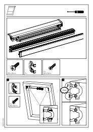
14 Attach Rail to Header Bracket<br />
Position opener on garage floor below the header bracket. Use<br />
packing material to protect the cover. Raise rail until holes in the<br />
header sleeve and holes in the header bracket align. Join with clevis<br />
pin (1). Insert ring fastener (2) to secure.<br />
NOTE: To enable the rail to clear sectional door springs, it may be<br />
necessary to lift opener onto a temporary support. The opener must<br />
either be secured to a support or held firmly in place by another<br />
person.<br />
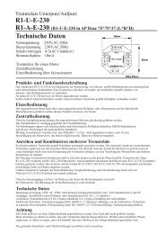
15 Position the Opener<br />
NOTE: A 25mm (1") board (1) is convenient for setting an ideal<br />
door-to-rail distance (unless headroom is not sufficient).<br />
Raise the opener onto a stepladder. Open garage door. Place a 25mm<br />
(1") board (1) laid flat on the top section of door near the centerline as<br />
shown. Rest the rail on the board.<br />
If the raised door hits the trolley, pull down on the trolley release arm<br />
to disconnect the inner and outer trolley sections. The trolley can<br />
remain disconnected until connecting door arm to trolley is completed.<br />
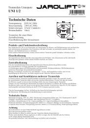
16 Hang the Opener<br />
The opener must be securely fastened to a structural support of<br />
the garage.<br />
Three representative installations are shown. Yours may be different.<br />
Hanging brackets (1) should be angled (Figure A) to provide rigid<br />
support. On finished ceilings, (Figure B) attach a sturdy metal bracket<br />
(not supplied) (4) to a structural support before installing the opener.<br />
For concrete ceiling mount, (Figure C), use concrete anchors (5)<br />
provided.<br />
On each side of opener measure the distance from the opener to the<br />
structural support (or ceiling).<br />
Cut both pieces of the hanging bracket to required lengths. Flatten one<br />
end of each bracket and bend or twist to fit the fastening angles. Do<br />
not bend at the bracket holes. Drill 4,5mm (3/16") pilot holes in the<br />
structural supports (or ceiling). Attach brackets to supports with wood<br />
screws (2).<br />
Lift opener and fasten to hanging brackets with screw, lock washer<br />
and nut (3). Check to make sure rail is centered over the door.<br />
REMOVE 25mm (1") board. Operate door manually. If door hits the<br />
rail, raise header bracket. Use rail grease and lubricate bottom surface<br />
of rail (6).<br />
17 Attach Emergency Release Rope & Handle<br />
Thread one end of rope (1) through hole in top of red handle so<br />
"NOTICE" reads right side up as shown (3). Secure with an overhand<br />
knot (2). Knot should be at least 25mm (1") from end of the rope to<br />
prevent slipping.<br />
Thread other end of rope through hole in release arm of the outer<br />
trolley (4). Adjust rope length so that handle is 1,8m (6 feet) above the<br />
floor. Secure with an overhand knot.<br />
NOTE: If it is necessary to cut rope, heat seal cut end with a match or<br />
lighter to prevent fraying.<br />
Connect Electric Power<br />
TO AVOID INSTALLATION DIFFICULTIES, DO NOT RUN THE<br />
GARAGE DOOR OPENER UNTIL INSTRUCTED TO DO SO.<br />
Connect the door opener only to an outlet controlled by a double<br />
pole switch.<br />
18<br />
Install Light<br />
Gently pull lens (2) downward until the lens hinge is in the fully open<br />
position. Do not remove the lens. Install a 24V/21W maximum light<br />
bulb (1) in the socket as shown. The light will turn on and remain lit for<br />
2-1/2 minutes when power is connected. After 2-1/2 minutes it will turn<br />
off. Reverse the procedure to close the lens.<br />
Replace burned out bulbs with rough service light bulbs.<br />
19 Fasten Door Bracket<br />
If you have a canopy garage door, a door arm conversion kit is required.<br />
Follow the installation instructions included with the replacement door<br />
arm. Exercise care in removing and assembling arm conversion kit. Keep<br />
fingers away from the sliding parts.<br />
NOTE: Horizontal and vertical reinforcement is needed for lightweight<br />
garage doors.<br />
Sectional and One-Piece Door Installation Procedure:<br />
Door bracket (1) has left and right side fastening holes. If your<br />
installation requires top and bottom fastening holes use both the door<br />
bracket and door bracket plate (2) as shown.<br />
1. Center door bracket (with or without door bracket plate, as required)<br />
at the top inside face of door as shown. Mark holes.<br />
A.Standard Sectional or One-piece doors: locate bracket at<br />
inside face of the door.<br />
B. Sectional doors with two horizontal roller channels: 150 -<br />
250mm below the top of the door.<br />
2. A. Wooden doors<br />
Drill 8mm holes (5/16") and fasten the door bracket with nut,<br />
lock washer, and carriage bolt (3).<br />
B. Sheet metal doors<br />
Fasten with wood screws (4).<br />
C. One-piece door optional<br />
Fasten with wood screws (4).<br />
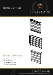
20 Assemble Door Arm<br />
A. ONE-PIECE DOOR INSTALLATION:<br />
Fasten the straight (1) and curved (2) door arm sections together to<br />
the longest possible length (with a 2 or 3 hole overlap) using hardware<br />
(3,4 and 5). With the door closed connect the straight door arm section<br />
(1) to the door bracket with clevis pin (6). Secure with ring fastener (7).<br />
Disconnect the inner and outer trolley. Slide the outer trolley back<br />
toward the opener and join the curved arm (2) to the connector hole in<br />
the trolley (8) with clevis pin (6). It may be necessary to lift the door<br />
slightly to make the connection. Secure with ring fastener (7).<br />
NOTE: When setting the up limit, the door should not have a<br />
“backward” slant when fully open. A slight backward slant (9) will<br />
cause unnecessary bucking and/or jerking operation as the door is<br />
bing opened or closed from the fully open position.<br />
B. SECTIONAL DOOR INSTALLATION:<br />
Connect according to Figure B, then proceed to Step 21.<br />
3-en