macchine da caffe' automatica automatic coffee machines
macchine da caffe' automatica automatic coffee machines
macchine da caffe' automatica automatic coffee machines

Create successful ePaper yourself
Turn your PDF publications into a flip-book with our unique Google optimized e-Paper software.
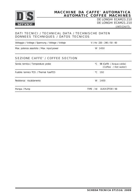
Volta<br />
ggio<br />
Max.<br />
poten<br />
za<br />
/ Voltag<br />
e / Span<br />
nung<br />
/ Volta<br />
ge<br />
/ Voltaj<br />
e<br />
as<br />
s orbita<br />
/ Max.<br />
input<br />
power<br />
1<br />
V / Hz<br />
2<br />
0 - 240<br />
/ 50<br />
- 60<br />
W 1450<br />
Son <strong>da</strong><br />
term<br />
ica<br />
/ Temp<br />
erat<br />
ure<br />
probe<br />
° C 98<br />
( Caffè<br />
/ Acqua cal<strong>da</strong>)<br />
(Coffee / Hot water)<br />
Fusi<br />
bile<br />
Resi<br />
sten<br />
za<br />
term<br />
ico<br />
TCO<br />
Pomp<br />
a / Pump<br />
/ Ther<br />
m<br />
risc<br />
al<strong>da</strong>m<br />
ento<br />
al<br />
fuse<br />
TCO<br />
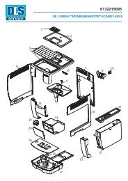
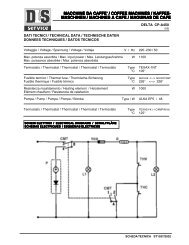
MACCHINE DA CAFFE ' AUTOMATICA<br />
AUTOMATIC COFFEE MACHINES<br />
DE LONGHI ECAM23.210<br />
DE LONGHI ECAM21.210<br />
DATI TECNICI / TECHNICAL DATA / TECHNISCHE DATEN<br />
DONNEES TECHNIQUES / DATOS TECNICOS<br />
SEZIONE CAFFE' / COFFEE SECTION<br />
TYPE<br />
° C 192<br />
W 1400<br />
/ W<br />
ULKA EP5W / 48<br />
(INT/CH/IT)<br />
SCHEDA TECNICA ST1516/ 2009
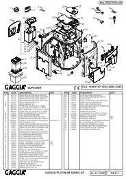
SCHEMA ELETTRICO / ELECTRICAL DIAGRAM<br />
BIANCO/WHITE<br />
BIANCO/WHITE<br />
ROSSO/RED<br />
M2<br />
ROSSO/RED<br />
M4<br />
VERDE/GREEN<br />
BIANCO/WHITE<br />
B<br />
M3<br />
POMPA/PUMP<br />
PUMP THERMAL PROTECTOR<br />
MOTOPROTETTORE POMPA<br />
P<br />
MARRONE/BROWN MARRONE/BROWN<br />
A<br />
MARRONE/BROWN<br />
SCHEDA DISPLAY<br />
DISPLAY PCB<br />
J1<br />
J5<br />
BIANCO/WHITE<br />
MOTORE TRASMISSIONE<br />
TRANSMISSION MOTOR<br />
B<br />
F1<br />
SCHEDA POTENZA<br />
POWER BOARD<br />
J13<br />
F2<br />
ROSSO/RED<br />
+<br />
+<br />
A<br />
F3<br />
ROSSO/RED<br />
MARRONE/BROWN<br />
NERO/BLACK<br />
M<br />
B<br />
F4<br />
-<br />
-<br />
2<br />
B<br />
F5<br />
J9 J6 J7 J8 J4<br />
BLU/BLUE<br />
F7<br />
F8<br />
SENSORE REED<br />
REED SENSOR<br />
MARRONE/BROWN<br />
BLU/BLUE<br />
I<br />
0<br />
A<br />
A<br />
A<br />
1 2 3 4<br />
GIA-VER<br />
YLW-GRN<br />
ROSSO/RED<br />
INTERRUTTORE ON/OFF<br />
ON/OFF SWITCH<br />
A<br />
NERO/BLACK<br />
BIANCO/WHITE<br />
SONDA TEMP.<br />
TEMP. PROBE<br />
M5<br />
NERO/BLACK<br />
M1<br />
BIANCO/WHITE<br />
B<br />
FLUSSIMETRO<br />
FLOWMETER<br />
GIA-VER/YLW-GRN<br />
TCO<br />
THERMAL CUT OFF<br />
TCO<br />
THERMAL CUT OFF<br />
B<br />
C<br />
ROSSO/RED<br />
BIANCO/WHITE<br />
C B<br />
D D<br />
CALDAIA/BOILER<br />
CELLA DI HALL<br />
HALL CELL<br />
M<br />
MACININO/COFFEE GRINDER<br />
LEGENDA MICRO / MICROSWITCHES<br />
Infusore alto / Infuser top position<br />
Infusore basso / Infuser bottom position<br />
Cassetto fondi / Coffee grounds container<br />
Tanica / Tank<br />
Rubinetto / Tap<br />
M1<br />
M2<br />
M3<br />
M4<br />
M5<br />
SCHEDA TECNICA ST1516/2009
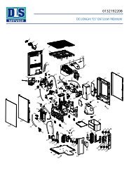
N<br />
L<br />
SCHEMA ELETTRICO / ELECTRICAL DIAGRAM<br />
SONDA TEMP.<br />
TEMP. PROBE<br />
FLUSSIMETRO<br />
FLOWMETER<br />
CELLA DI HALL<br />
HALL SENSOR<br />
M1 M5<br />
MOTORE TRASMISSIONE<br />
TRANSMISSION MOTOR<br />
SENSORE REED<br />
REED SENSOR<br />
F7<br />
INTERRUTTORE ON/OFF<br />
ON/OFF SWITCH<br />
J9<br />
J6<br />
- +<br />
J7<br />
J8<br />
J4<br />
F5<br />
M<br />
J13<br />
SCHEDA POTENZA<br />
POWER BOARD<br />
F8 F4 F3 F2 F1<br />
L L L L<br />
3<br />
J5<br />
J1<br />
SCHEDA DISPLAY<br />
DISPLAY PCB<br />
RESISTENZA<br />
HEATING EL.<br />
TCO<br />
THERMAL CUT OFF<br />
TCO<br />
THERMAL CUT OFF<br />
M<br />
MACININO/COFFEE GRINDER<br />
P<br />
M2<br />
POMPA/PUMP<br />
PUMP THERMAL PROTECTOR<br />
MOTOPROTETTORE POMPA<br />
M4<br />
M3<br />
SCHEDA TECNICA ST1516/2009
Picture 1<br />
Picture 3.<br />
Take off drip tray<br />
and waste container<br />
Picture 5<br />
ACCESSIBILITY<br />
Picture 2.<br />
Take off water<br />
tank<br />
Picture 4.<br />
Unscrew the 5 indicated screws<br />
(Torx T20)<br />
5.1 Remove back panel 5.2 Unhook side panels<br />
Page 1
6.1 Take off plastic hook first<br />
6.5<br />
Take off cable<br />
6.4<br />
Lift upper panel<br />
Picture 6 - TO REMOVE CONTROL PANEL<br />
6.3 Unscrew the 4<br />
indicated screws (2 on the<br />
back +2 on the sides)<br />
6.2 Take off knob and<br />
frother<br />
6.6<br />
Unscrew the 2 indicated screws.<br />
Then, lift with care the Control Panel<br />
Page 2
Picture 7 - TO REMOVE COFFEE GRINDER<br />
8.1<br />
Take off cable and<br />
take out flowmeter<br />
7.2<br />
Lift <strong>coffee</strong> grinder pushing<br />
it back with delicacy<br />
7.1<br />
Take off cables on the right<br />
side of the board<br />
7.3<br />
To separate <strong>coffee</strong> grinder<br />
unscrew the indicated screw.<br />
Picture 8 - TO REMOVE FLOWMETER<br />
Page 3
9.2<br />
Take off pump<br />
9.1<br />
Take off the spring<br />
and then the tube<br />
Attention: Some water could come out<br />
from the tube, since the water circuit is<br />
empting out<br />
Picture 10 - TO REMOVE BOARD<br />
Picture 9 - TO REMOVE PUMP<br />
9.3<br />
Attention: After you have taken off cables,<br />
you will have to take off pump thermal protector.<br />
Since it is glued, you will have to use a certain strength.<br />
Remember to glue it again when you will reassemble it<br />
10.1<br />
Take off the 4 indicated screws. After you have taken off cables, take out the board<br />
Page 4
11.1<br />
Unscrew the 4 indicated screw<br />
you find on the rear of the motor<br />
Picture 11 - TO REMOVE MOTOR<br />
11.2<br />
take off the 2 cables<br />
and then take off<br />
the DC motor.<br />
Pay attention to<br />
polarity when<br />
replacing it<br />
Page 5
12.1<br />
Take off cables<br />
12.2<br />
Unscrew the 2 indicated screws<br />
Picture 12 - TO REMOVE TAP STEAM/HOT WATER<br />
12.3<br />
Take off microswitch<br />
Page 6
13.3<br />
Take off the spring<br />
indicated by the arrow and<br />
then the tube<br />
13.2<br />
Take off the<br />
tube<br />
Picture 13 - TO REMOVE BOILER<br />
13.1<br />
Take off the indicated 2 springs<br />
and the 4 screws.<br />
13.4<br />
Take off the cover.<br />
Then unscrew the 2 indicated<br />
screws to disassemble<br />
the boiler<br />
Attention: to take off the boiler,<br />
push with delicacy the plastic panel<br />
Page 7
Picture14 - TO REMOVE INFUSER KIT<br />
Figura 14.1<br />
Open infuser box.<br />
Push the 2 buttons and take out<br />
the infuser<br />
Page 8
15.1<br />
Unscrew the 10 indicated screws<br />
Picture 15 - TO REMOVE TRANSMISSION KIT<br />
15.2<br />
Open infuser box<br />
15.4<br />
Take off the indicated screw<br />
15.3<br />
Unscrew the 2 indicated screws<br />
(Torx T20) and remove the slider<br />
Now the TRASMISSION KIT is free and can be removed<br />
Page 9
15.6<br />
Pay attention, when you take off the<br />
plastic component, to the 2 indicated<br />
metal spacers<br />
(ATTENTION: about metal<br />
spacers see Technical Info<br />
IT0181)<br />
15.5<br />
To remoce the Feeler Board (hall Sensor)<br />
unscrew the 2 indicated screw to remove<br />
the Hall sensor<br />
Page 10
Picture 16 - TO REMOVE COFFEE SPOUT<br />
16.1<br />
Unscrew the 2 indicated screws<br />
and remove the <strong>coffee</strong> spout<br />
16.2<br />
Pay attention to the spring<br />
assembled with slider<br />
Pag. 11
Picture 17 - TO REMOVE VALVE ASSEMBLY<br />
(see Technical Info IT0181)<br />
17.1<br />
Take off the 2 springs<br />
and then the<br />
tubes<br />
17.3<br />
Take off the spring<br />
and then the tube<br />
which goes from<br />
<strong>coffee</strong> spout to<br />
infuser<br />
17.5<br />
Take off microswitch<br />
17.2<br />
Unscrew the 2 indicated screws<br />
using an Allen key (4)<br />
17.4<br />
Unscrew the indicated screw<br />
to take off microswitch<br />
Page 12
Picture 18 - HOW TO ALIGN VALVE<br />
Lift the infuser up to to touch the valve, without pushing with strength: it has only to be<br />
aligned to the valve.<br />
Once you aligned it, fix the 2 screws (pic. 18.2) using an Allen key.<br />
18.2<br />
Fit in the tube<br />
and then<br />
the spring<br />
18.1<br />
Screw the 2 indicated screws<br />
using an Allen key (4)<br />
Page 13
Picture 19 - MICROSWITCH AND<br />
WATER REED POSITION<br />
19.3<br />
Steam tap<br />
microswitch<br />
19.1<br />
Water Tank<br />
microswitch<br />
ATTENTION: please, pay attention<br />
to never bypass microswitch.<br />
If you should do it<br />
infuser motor would be on<br />
ATTENTION: Water Tank led,<br />
Waste container led<br />
and Steam tap led blink<br />
when micro are open<br />
19.4<br />
Infuser bottom limit<br />
microswitch<br />
19.5<br />
Waste container<br />
microswitch<br />
19.6<br />
Reed switch<br />
water tank<br />
19.2<br />
Infuser<br />
Upper Limit<br />
microswitch<br />
Page 14
WATER CIRCUIT<br />
VALVE<br />
BOILER<br />
INFUSER<br />
SAFETY<br />
VALVE<br />
EXPANSION<br />
CHAMBER<br />
PUMP<br />
DUMPER<br />
FLOWMETER<br />
DRIP TRAY<br />
WATER TANK<br />
FILTER
TEST PROCEDURE<br />
Put Steam Tap on 0.<br />
Plug the machine ON.<br />
Press and hold: 1 Coffee + Steam buttons<br />
Press On/Off Switch (position I)<br />
NOTE: Release bttons when motor<br />
starts moving.<br />
TEST PROCEDURE FOR<br />
ECAM23.210 INTENSA<br />
Pressing each icon below, we can<br />
manually check the devices:<br />
icon device<br />
Coffe Boiler ON<br />
Grinder ON<br />
Motor UP, till “UPPER LIMIT<br />
Motor DOWN, till “BOTTOM<br />
LIMIT<br />
Water Pump ON<br />
NOTE: Every led blinks when the microswitch is open<br />
To EXIT the procedure, press On/Off Swicth (position 0) or unplug the machine.
DISPLAY TEST PROCEDURE<br />
To enter the DISPLAY test:<br />
Plug the machine ON.<br />
Press and hold: 1 Coffee + Steam buttons<br />
Press On/Off Switch (position I)<br />
Note: Release buttons some seconds<br />
after icons blinked.<br />
DISPLAY TEST PROCEDURE FOR<br />
ECAM23.210 INTENSA<br />
Pressing each icon the display<br />
will show following message<br />
icon message<br />
Turning the knob,<br />
the display will show<br />
the bar increasing<br />
or decreasing.<br />
NOTE: After display Test performing, you need to intialize the machine.<br />
To EXIT the procedure, press On/Off Swicth (position 0) or unplug the machine.<br />
Test procedure ends <strong><strong>automatic</strong>a</strong>lly 1 minute after you complete it.
Figura 1<br />
Figura 3.<br />
Togliere il cassetto<br />
reccolta fondi<br />
Figura 5<br />
5.1 Sfilare lo schienale<br />
ACCESSIBILITA’<br />
Figura 2.<br />
Togliere serbatoio<br />
acqua<br />
Figura 4.<br />
Svitare le 5 viti indicate<br />
(Torx T20)<br />
Figura 5.2 Sganciare i fianchi<br />
Pag. 1
6.1 Togliere innanzitutto<br />
la forcina in plastica<br />
6.4<br />
Sfilare copertura superiore<br />
6.5<br />
Sganciare la piattella<br />
Figura 6 - SMONTAGGIO CRUSCOTTO<br />
6.6<br />
Togliere le due viti<br />
del cruscotto. Sollevare<br />
quindi leggermente<br />
verso l’altro per sganciarlo<br />
6.3 Togliere le viti laterali<br />
e posteriori (2+2)<br />
6.2 Sfilare la manopola<br />
ed il cappuccinatore<br />
Pag. 2
Figura 7 - SMONTAGGIO MACININO<br />
8.1<br />
Sfilare il connettore<br />
ed estrarre verso<br />
l’esterno<br />
il flussimetro<br />
7.2<br />
Sollevare il macinino<br />
spostandolo lievemente<br />
verso la parte posteriore<br />
7.1<br />
Sganciare i cavetti del motore<br />
<strong>da</strong>l lato destro della sche<strong>da</strong><br />
7.3<br />
Per disassemblare il macinino<br />
togliere la vite indicata<br />
Figura 8 - SMONTAGGIO FLUSSIMETRO<br />
Pag. 3
9.2<br />
Sfilare la pompa<br />
9.1<br />
Togliere la forcina<br />
di aggancio e quindi<br />
sfilare il tubo<br />
Attenzione: <strong>da</strong>l tubo potrebbe uscire<br />
una piccola quantità d’acqua, in quanto<br />
il circuito i<strong>da</strong>raulico si svuota<br />
Figura 10 - SMONTAGGIO SCHEDA<br />
Figura 9 - SMONTAGGIO POMPA<br />
9.3<br />
Attenzione: Dopo aver sganciato il cablaggio,<br />
sfilare il klixon. Essendo incollato, esercitare<br />
una certa forze. Ricor<strong>da</strong>rsi di incollarlo<br />
nuovamente<br />
10.1<br />
Togliere le quattro viti indicate. Dopo aver staccato i cablaggi, sfilare la sche<strong>da</strong><br />
Pag. 4
11.1<br />
Togliere le 4 viti di fissaggio del motore,<br />
raggiungibili <strong>da</strong>lla parte posteriore<br />
Figura 11 - SMONTAGGIO MOTORE<br />
11.2<br />
staccare i due cavetti<br />
e sfilare il motore<br />
a corrente continua.<br />
Fare attenzione alla<br />
polarità al momento<br />
della sostituzione<br />
Pag. 5
12.1<br />
Scollegare i cavi<br />
12.2<br />
Togliere le viti indicate<br />
Figura 12 - SMONTAGGIO RUBINETTO<br />
12.3<br />
Sfilare il micro<br />
Pag. 6
13.3<br />
Togliere la forcina indivata<br />
<strong>da</strong>lla freccia e sfilare il tubo<br />
13.2<br />
Stccare il tubo<br />
indicato<br />
Figura 13 - SMONTAGGIO CALDAIA<br />
13.1<br />
Sfilare le 2 forcine<br />
e togliere le 4 viti<br />
13.4<br />
Una volta tolta la chiusura,<br />
svitare le viti indicate per<br />
estrarre la cla<strong>da</strong>ia<br />
Attenzione: per togliere la<br />
cal<strong>da</strong>ia, spingere con delicatezza<br />
il pannello in plastica<br />
Pag. 7
Figura 14 - ESTRAZIONE INFUSORE<br />
Figura 14.1<br />
Aprire il vano infusore.<br />
Premere i due tasti indicati<br />
ed estrarre l’infusore<br />
Pag. 8
15.1<br />
Togliere le 10 viti indicate<br />
Figura 15 - SMONTAGGIO GRUPPO MOVIMENTAZIONE<br />
15.2<br />
Aprire vano infusore<br />
15.4<br />
Togliere la vite di fissaggio della slitta<br />
15.3<br />
Togliere le 2 viti indicate<br />
(Torx T20)<br />
Ora il GRUPPO MOVIMENTAZIONE può essere estratto<br />
Pag. 9
15.6<br />
Fare attenzione, nel momento in cui<br />
si toglie la slitta, ai 2 distanziali indicati nel<br />
disegno<br />
(ATTENZIONE: per i<br />
distanziali vedere info<br />
IT0181)<br />
15.5<br />
Togliere le 2 viti indicate per<br />
smontare la Sche<strong>da</strong> Sensore (cella di Hall) della<br />
slitta<br />
Pag. 10
Figura 16 - SMONTAGGIO EROGATORE CAFFE’<br />
Figura 16.1<br />
Togliere le 2 viti indicate per smontare<br />
l’erogatore<br />
16.2<br />
Fare attenzione alla molla<br />
montata sul cursore<br />
Pag. 11
Figura 17 - SMONTAGGIO MECCANOVALVOLA<br />
(ATTENZIONE: vedere info IT0181)<br />
17.1<br />
Togliere le 2 forcine e<br />
sfilare i tubi<br />
17.3<br />
Togliere la forcina e<br />
sfilare il tubo che<br />
<strong>da</strong>ll’erogatore<br />
arriva all’infusore<br />
17.5<br />
Estrarre il microint.<br />
17.2<br />
Utilizzando una chiave a brugola (4)<br />
togliere le due viti di fissaggio della<br />
staffa<br />
17.4<br />
Per togliere il microinterruttore,<br />
svitare la vite indicata<br />
Pag. 12
Figura 18 - ALLINEARE LA MECCANOVALVOLA<br />
Far salire l’infusore fino a farlo arrivare a contatto della meccanovalvola, senza esercitare pressione<br />
per farli entrare in contatto: devono solo essere allineati.<br />
Una volta completata l’operazione, fissare le due viti (fig. 18.2) con una chiave a brugola<br />
18.2<br />
Inserire il tubo<br />
e la forcina<br />
18.1<br />
Avviatare le 2 viti indicate<br />
con una chiave a brugola (4)<br />
Page 13
Figura 19. POSIZIONAMENTO<br />
MICROINTERRUTTORI E REED<br />
19.1<br />
Microinterruttore Tanica<br />
ATTENZIONE: fate attenzione<br />
a non bypassare il micro:<br />
se doveste farlo, il motore<br />
infusore resterebbe in funzione<br />
ATTENZIONE: i micro Tanica,<br />
Cassetto Fondi e Rubinetto fanno<br />
lampeggiari i propri led quando<br />
aperti<br />
19.3<br />
Microinterruttore<br />
Rubinetto<br />
19.4<br />
Microinterruttore<br />
inizio corsa<br />
Infusore<br />
19.5<br />
Microinterruttore<br />
Cassetto fondi<br />
19.6<br />
Reed tanica<br />
19.2<br />
Microint.<br />
fine corsa<br />
Infusore<br />
Pag. 14
SCHEMA IDRAULICO<br />
MECCANOVALVOLA<br />
GENERATORE<br />
INFUSORE<br />
VALVOLA DI<br />
SICUREZZA<br />
CAMERA DI<br />
ESPANSIONE<br />
POMPA<br />
DUMPER<br />
FLUSSIMETRO<br />
VASCHETTA<br />
DI RACCOLTA<br />
SERBATOIO<br />
FILTRO
PROCEDURA<br />
Chiudere il rubinetto vapore (pos. 0).<br />
Attaccare il cavo di rete.<br />
Tenere premuti i tasti: 1 Tazza + Vapore<br />
Premere l’interruttore On/Off (pos. I)<br />
PROCEDURA DI TEST PER LA<br />
ECAM23.210 INTENSA<br />
NOTA: Rilasciare i tasti quando il<br />
motore quando inizia la movimentazione<br />
Premendo le varie icone, si<br />
alimentano i seguenti dispositivi:<br />
icona dispositivo<br />
Cal<strong>da</strong>ia Caffè ON<br />
Motore Macinino ON<br />
Motore, verso l’alto “Micro fine<br />
corsa” e verso il basso<br />
“Micro inizio corsa”<br />
Pompa Acqua ON<br />
NOTA: I micro accendono i led corrispondenti quando attivati.<br />
Per USCIRE <strong>da</strong>lla procedura, premere l’interruttore On/Off (pos. 0) o staccare<br />
il cavo di alimentazione.
PROCEDURA DI TEST DISPLAY<br />
Per entrare nella procedura di test:<br />
Attaccare il cavo di rete.<br />
Tenere premuti i tasti: 1 Tazza + Vapore<br />
Premere l’interruttore On/Off (pos. I)<br />
Nota: Rilasciare i tasti qualche secondo<br />
dopo la visualizzazione di tutte le icone.<br />
PROCEDURA DI TEST DISPLAY PER<br />
ECAM23.210 INTENSA<br />
Premendo su ciascuna icona, si<br />
visualizza il seguente messaggio<br />
icona messaggio<br />
Girando la manopola,<br />
il Display mostrerà la<br />
barra di incremento e<br />
decremento<br />
NOTA: Dopo aver eseguito il test, è necessario inizializzare la macchina.<br />
Per USCIRE <strong>da</strong>lla procedura, premere l’interruttore On/Off (pos. 0) o staccare<br />
il cavo di alimentazione.<br />
La <strong>macchine</strong> esce <strong><strong>automatic</strong>a</strong>mente <strong>da</strong>lla procedura di test dopo un minuto.