DUAL ®& DUAL ® SH SINGLE ®& SINGLE ® SH - Expert-CM
DUAL ®& DUAL ® SH SINGLE ®& SINGLE ® SH - Expert-CM
DUAL ®& DUAL ® SH SINGLE ®& SINGLE ® SH - Expert-CM

You also want an ePaper? Increase the reach of your titles
YUMPU automatically turns print PDFs into web optimized ePapers that Google loves.
CAUTION<br />
! ! CAUTION HOT WATER<br />
. CRACKED<br />
. SCRATCHED<br />
. BOILED DRY<br />
. HEATED WHEN EMPTY<br />
. USED ON HIGH FLAME<br />
. OR EXPOSED ELECTRIC<br />
ELEMENTS<br />
DISCARD DECANTER<br />
IF:<br />
FUNNEL CONTENTS<br />
ARE HOT<br />
FAILURE TO COMPLY RISKS INJURY<br />
PN: 658 1985 BUNN-O-MATIC CORPORATION<br />
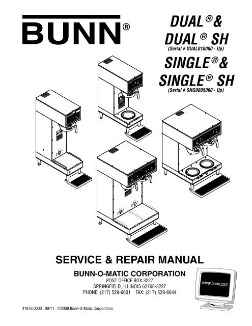
<strong>DUAL</strong> <strong>®</strong> &<br />
<strong>DUAL</strong> <strong>®</strong> <strong>SH</strong><br />
(Serial # <strong>DUAL</strong>010000 - Up)<br />
<strong>SINGLE</strong> <strong>®</strong> &<br />
<strong>SINGLE</strong> <strong>®</strong> <strong>SH</strong><br />
(Serial # SNG0005000 - Up)<br />
!<br />
READY SELECTOR<br />
ON / WARMER START<br />
SERVICE & REPAIR MANUAL<br />
41976.0000 09/11 ©2009 Bunn-O-Matic Corporation<br />
!<br />
CAUTION<br />
. CRACKED<br />
. SCRATCHED<br />
. BOILED DRY<br />
. HEATED WHEN EMPTY<br />
. USED ON HIGH FLAME<br />
. OR EXPOSED ELECTRIC<br />
ELEMENTS<br />
DISCARD DECANTER<br />
IF:<br />
FUNNEL CONTENTS<br />
ARE HOT<br />
FAILURE TO COMPLY RISKS INJURY<br />
PN: 658 1985 BUNN-O-MATIC CORPORATION<br />
!<br />
CAUTION<br />
!<br />
. CRACKED<br />
. SCRATCHED<br />
. BOILED DRY<br />
. HEATED WHEN EMPTY<br />
. USED ON HIGH FLAME<br />
. OR EXPOSED ELECTRIC<br />
ELEMENTS<br />
C A U T I O N : W A R M E R S A N D S U R F A C E S A R E H O T<br />
BUNN-O-MATIC CORPORATION<br />
POST OFFICE BOX 3227<br />
SPRINGFIELD, ILLINOIS 62708-3227<br />
PHONE: (217) 529-6601 FAX: (217) 529-6644<br />
! CAUTION HOT WATER<br />
DISCARD DECANTER<br />
IF:<br />
FUNNEL CONTENTS<br />
ARE HOT<br />
FAILURE TO COMPLY RISKS INJURY<br />
PN: 658 1985 BUNN-O-MATIC CORPORATION<br />
! CAUTION HOT WATER<br />
CAUTION<br />
. CRACKED<br />
. SCRATCHED<br />
. BOILED DRY<br />
. HEATED WHEN EMPTY<br />
. USED ON HIGH FLAME<br />
. OR EXPOSED ELECTRIC<br />
ELEMENTS<br />
DISCARD DECANTER<br />
IF:<br />
FUNNEL CONTENTS<br />
ARE HOT<br />
FAILURE TO COMPLY RISKS INJURY<br />
PN: 658 1985 BUNN-O-MATIC CORPORATION<br />
1 gal 1 1⁄2 gal<br />
1⁄2 gal<br />
L<br />
E<br />
F<br />
T<br />
GRINDER<br />
R<br />
I<br />
G<br />
H<br />
T<br />
! CAUTION HOT WATER<br />
C AU T I O N : WA R M E R S A N D S U R FA C E S A R E H O T<br />
1 gal 1 1⁄2 gal<br />
1⁄2 gal<br />
START ON / WARMER SELECTOR READY
BUNN-O-MATIC COMMERCIAL PRODUCT WARRANTY<br />
Bunn-O-Matic Corp. (“BUNN”) warrants equipment manufactured by it as follows:<br />
1) All equipment other than as specified below: 2 years parts and 1 year labor.<br />
2) Electronic circuit and/or control boards: parts and labor for 3 years.<br />
3) Compressors on refrigeration equipment: 5 years parts and 1 year labor.<br />
4) Grinding burrs on coffee grinding equipment to grind coffee to meet original factory screen sieve analysis:<br />
parts and labor for 3 years or 30,000 pounds of coffee, whichever comes first.<br />
These warranty periods run from the date of installation BUNN warrants that the equipment manufactured by<br />
it will be commercially free of defects in material and workmanship existing at the time of manufacture and<br />
appearing within the applicable warranty period. This warranty does not apply to any equipment, component or<br />
part that was not manufactured by BUNN or that, in BUNN’s judgment, has been affected by misuse, neglect,<br />
alteration, improper installation or operation, improper maintenance or repair, damage or casualty. This warranty is<br />
conditioned on the Buyer 1) giving BUNN prompt notice of any claim to be made under this warranty by telephone<br />
at (217) 529-6601 or by writing to Post Office Box 3227, Springfield, Illinois 62708-3227; 2) if requested by<br />
BUNN, shipping the defective equipment prepaid to an authorized BUNN service location; and 3) receiving prior<br />
authorization from BUNN that the defective equipment is under warranty.<br />
THE FOREGOING WARRANTY IS EXCLUSIVE AND IS IN LIEU OF ANY OTHER WARRANTY, WRITTEN OR<br />
ORAL, EXPRESS OR IMPLIED, INCLUDING, BUT NOT LIMITED TO, ANY IMPLIED WARRANTY OF EITHER<br />
MERCHANTABILITY OR FITNESS FOR A PARTICULAR PURPOSE. The agents, dealers or employees of BUNN<br />
are not authorized to make modifications to this warranty or to make additional warranties that are binding on<br />
BUNN. Accordingly, statements by such individuals, whether oral or written, do not constitute warranties and<br />
should not be relied upon.<br />
If BUNN determines in its sole discretion that the equipment does not conform to the warranty, BUNN, at its<br />
exclusive option while the equipment is under warranty, shall either 1) provide at no charge replacement parts<br />
and/or labor (during the applicable parts and labor warranty periods specified above) to repair the defective<br />
components, provided that this repair is done by a BUNN Authorized Service Representative; or 2) shall replace<br />
the equipment or refund the purchase price for the equipment.<br />
THE BUYER’S REMEDY AGAINST BUNN FOR THE BREACH OF ANY OBLIGATION ARISING OUT OF THE SALE OF<br />
THIS EQUIPMENT, WHETHER DERIVED FROM WARRANTY OR OTHERWISE, <strong>SH</strong>ALL BE LIMITED, AT BUNN’S<br />
SOLE OPTION AS SPECIFIED HEREIN, TO REPAIR, REPLACEMENT OR REFUND.<br />
In no event shall BUNN be liable for any other damage or loss, including, but not limited to, lost profits, lost sales,<br />
loss of use of equipment, claims of Buyer’s customers, cost of capital, cost of down time, cost of substitute<br />
equipment, facilities or services, or any other special, incidental or consequential damages.<br />
392, AutoPOD, AXIOM, BrewLOGIC, BrewMETER, Brew Better Not Bitter, BrewWISE, BrewWIZARD, BUNN Espress, BUNN<br />
Family Gourmet, BUNN Gourmet, BUNN Pour-O-Matic, BUNN, BUNN with the stylized red line, BUNNlink, Bunn-OMatic,<br />
Bunn-O-Matic, BUNNserve, BUNNSERVE with the stylized wrench design, Cool Froth, DBC, Dr. Brew stylized Dr. design,<br />
Dual, Easy Pour, EasyClear, EasyGard, FlavorGard, Gourmet Ice, Gourmet Juice, High Intensity, iMIX, Infusion Series,<br />
Intellisteam, My Café, PowerLogic, Quality Beverage Equipment Worldwide, Respect Earth, Respect Earth with the stylized<br />
leaf and coffee cherry design, Safety-Fresh, savemycoffee.com, Scale-Pro, Silver Series, Single, Smart Funnel, Smart<br />
Hopper, SmartWAVE, Soft Heat, SplashGard, The Mark of Quality in Beverage Equipment Worldwide, ThermoFresh, Titan,<br />
A Partner You Can Count On, Air Brew, Air Infusion, Beverage Bar Creator, Beverage Profit Calculator, Brew better, not<br />
bitter., BUNNSource, Coffee At Its Best, Cyclonic Heating System, Digital Brewer Control, Nothing Brews Like a BUNN,<br />
Pouring Profits, Signature Series, Tea At Its Best, Phase Brew, The Horizontal Red Line, trifecta, Ultra, Velocity Brew are<br />
either trademarks or registered trademarks of Bunn-O-Matic Corporation.<br />
Page 2<br />
41976 050511
TROUBLE<strong>SH</strong>OOTING<br />
A troubleshooting guide is provided to suggest probable causes and remedies for the most likely problems<br />
encountered. If the problem remains after exhausting the troubleshooting steps, contact the Bunn-O-Matic<br />
Technical Service Department.<br />
• Inspection, testing, and repair of electrical equipment should be performed only by qualified<br />
service personnel.<br />
• All electronic components have 120 - 240 volt ac and low voltage dc potential on their terminals.<br />
Shorting of terminals or the application of external voltages may result in board failure.<br />
• Intermittent operation of electronic circuit boards is unlikely. Board failure will normally be permanent.<br />
If an intermittent condition is encountered, the cause will likely be a switch contact or<br />
a loose connection at a terminal or crimp.<br />
• Solenoid removal requires interrupting the water supply to the valve. Damage may result if solenoids<br />
are energized for more than ten minutes without a supply of water.<br />
• The use of two wrenches is recommended whenever plumbing fittings are tightened or loosened.<br />
This will help avoid twists and kinks in the tubing.<br />
• Make certain that all plumbing connections are sealed and electrical connections tight and isolated.<br />
•<br />
WARNING<br />
This brewer is heated at all times. Keep away from combustibles.<br />
• Exercise extreme caution when servicing electrical equipment.<br />
• Disconnect the brewer from the power source when servicing, except when electrical tests are<br />
specified.<br />
• Follow recommended service procedures.<br />
• Replace all protective shields or safety notices.<br />
Problem<br />
Probable Cause<br />
Remedy<br />
Equipment will not operate.<br />
Brew cycle will not start.<br />
1. No power or incorrect voltage.<br />
1. No water<br />
2. Water strainer/flow control<br />
(.750 GPM)<br />
Page 3<br />
(A1) Check the terminal block for<br />
120 volts across the red and white<br />
terminals and the black and white<br />
terminals on 120V, 120/208 or<br />
120/240 volt brewers.<br />
(A2) Check the terminal block for 200<br />
volts on "B Series" brewers or 240<br />
volts on "A Series" brewers across<br />
the red and black terminals.<br />
(B) Check circuit breakers or fuses.<br />
Check plumbing and shut-off<br />
valves<br />
(A) Direction of flow arrow must be<br />
pointing towards brewer.<br />
(B) Remove the strainer/flow control<br />
and check for obstructions. Clear or<br />
replace.<br />
41976 031709
TROUBLE<strong>SH</strong>OOTING (cont.)<br />
Problem<br />
Brew cycle will not start (cont.)<br />
Automatic refill will not operate<br />
Probable Cause<br />
3. ON/OFF switch<br />
4. Start switch<br />
5. Timer<br />
6. Dispense Valve<br />
7. Control Assembly (Electronic)<br />
8. Server not in place (<strong>SH</strong> models)<br />
1. No water<br />
2. Water strainer/flow control<br />
3. Solenoid Valve<br />
4. Limit thermostat (Electro/mechanical<br />
and Electronic)<br />
5. Overflow protection switch<br />
6. (A) Level control board & level<br />
probe. (Electro/mechanical controlled)<br />
(B) Electronic controls<br />
Page 4<br />
Remedy<br />
Refer to Service - ON/OFF switch for<br />
testing procedures.<br />
Refer to Service - Start switch for<br />
testing procedures.<br />
Refer to Service - Timer for testing<br />
procedures.<br />
Refer to Service - Dispense valve<br />
for testing procedures.<br />
Refer to Service - Control assembly<br />
for testing procedures.<br />
Make sure server is in place and<br />
server present lamp is lit.<br />
Check plumbing and shut-off valves.<br />
(A) Direction of flow arrow must be<br />
pointing towards brewer.<br />
(B) Remove the strainer/flow control<br />
and check for obstructions. Clear or<br />
replace.<br />
Refer to Service - Solenoid valve for<br />
testing procedures.<br />
Refer to Service - Limit thermostat<br />
for testing procedures.<br />
Refer to Service - Overflow protection<br />
switch for testing procedures.<br />
Refer to Service - Level control board<br />
for testing procedures.<br />
Refer to Service - Electronic controls<br />
for testing procedures.<br />
41976 031709
TROUBLE<strong>SH</strong>OOTING (cont.)<br />
Problem<br />
Beverage level will not adjust<br />
(Selector switch in any position)<br />
Water flows into tank continuously<br />
(On/Off Switch "OFF").<br />
Water flows into tank continuously<br />
(ON/OFF switch "ON").<br />
Water from tank is not hot<br />
Probable Cause<br />
1. Brew Selector switch<br />
1. Solenoid valve<br />
2A. Level control board and level<br />
probe (Electro/mechanical)<br />
2B. Control assembly (Electronic)<br />
3. Overflow protection switch<br />
1. Timer<br />
1. Limit thermostat<br />
CAUTION - Do not eliminate or<br />
bypass limit thermostat. Use only<br />
replacement part #23717.0001<br />
2A. Control Thermostat (Electro/<br />
mechanical)<br />
2B. Control assembly (Electronic)<br />
3. Contactor (Brewers with Recovery<br />
Booster)<br />
4. Tank heaters<br />
5. Triac assembly (Electronic)<br />
Page 5<br />
Remedy<br />
Refer to Service - Selector switch<br />
for testing procedures.<br />
Refer to Service - Solenoid valve for<br />
testing procedures.<br />
Refer to Service - Level control board<br />
for test procedures.<br />
Refer to Service - Control assembly<br />
for testing procedures.<br />
Refer to Service - Timer for testing<br />
procedures.<br />
Refer to Service - Overflow protection<br />
switch for testing procedures.<br />
Refer to Service -Limit thermostat<br />
for testing procedures.<br />
Refer to Service - Control Thermostat<br />
for testing procedures.<br />
Refer to Service - Control assembly<br />
for testing procedure.<br />
Refer to Service - Contactor for testing<br />
procedures.<br />
Refer to Service - Tank heaters for<br />
testing procedures.<br />
Refer to Service - Triac assembly for<br />
testing procedures.<br />
41976 031709
TROUBLE<strong>SH</strong>OOTING (cont.)<br />
Problem<br />
Water from tank is not hot (cont.).<br />
Server warmer is not hot.<br />
Spitting or unusual steaming from<br />
sprayhead or airvents.<br />
Inconsistent beverage level in<br />
server.<br />
Probable Cause<br />
6. Relay (Brewers with Recovery<br />
Booster)<br />
1. ON/OFF switch<br />
2. Warmer element<br />
1A. Control thermostat (Electro/<br />
mechanical)<br />
1B. Control assembly (Electronic)<br />
2. Triac assembly (Electronic)<br />
3. Lime build-up<br />
CAUTION - Tank and tank components<br />
should be delimed regularly<br />
depending on local water conditions.<br />
Excessive mineral build-up on<br />
stainless steel surfaces can initiate<br />
corrosive reactions resulting in serious<br />
leaks.<br />
1. Strainer/flow control<br />
2. Improper water pressure<br />
Page 6<br />
Remedy<br />
Refer to Service - Relay for testing<br />
procedures.<br />
Refer to Service - ON/OFF switch for<br />
testing procedures.<br />
Refer to Service - Warmer element<br />
for testing procedures.<br />
Refer to Service - Control thermostat<br />
for testing procedures.<br />
Refer to Service - Control assembly<br />
for testing procedures.<br />
Refer to Service - Triac assembly for<br />
testing procedures.<br />
Inspect the tank assembly for excessive<br />
lime deposits. Delime as<br />
required.<br />
(A) Direction of flow arrow must be<br />
pointing towards the brewer.<br />
(B) Remove the strainer/flow control<br />
and check for obstructions. Clear<br />
or replace.<br />
Check operating water pressure to<br />
the brewer. It must be between 20<br />
and 90 psi (138 and 620 kPa) .<br />
41976 031709
TROUBLE<strong>SH</strong>OOTING (cont.)<br />
Problem<br />
Inconsistent beverage level in<br />
server (cont.).<br />
Consistently high or low beverage<br />
level in server.<br />
Dripping from sprayhead.<br />
Water overflows filter.<br />
Beverage overflows server.<br />
Weak beverage.<br />
Probable Cause<br />
3. Dispense valve<br />
1. Timer adjustment<br />
1. Dispense valve<br />
1. Bypass valve<br />
2. Needle Valve<br />
3. Type of paper filters<br />
4. No sprayhead<br />
1. Beverage left in server<br />
2. Timer adjustment<br />
3. Dispense valve<br />
1. Type of paper filters<br />
2. Coffee<br />
Page 7<br />
Remedy<br />
Refer to Service - Dispense valve for<br />
testing procedures.<br />
Adjust the timer as required to<br />
achieve the recommended volume<br />
for each brew cycle.<br />
Refer to Service - Dispense valve<br />
for testing procedures.<br />
Refer to Installation & Operating<br />
Guide, Initial Set-Up.<br />
Refer to Installation & Operating<br />
Guide, Initial Set-Up<br />
BUNN paper filters should be used<br />
for proper extraction.<br />
Check sprayhead<br />
The brew cycle should be started<br />
only with an empty server under<br />
the funnel.<br />
Adjust the timer as required to<br />
achieve the recommended volume<br />
for each brew cycle.<br />
Refer to Service - Timer for testing<br />
procedures.<br />
Refer to Service - Dispense valve for<br />
testing procedures.<br />
BUNN paper filters should be used<br />
for proper extraction.<br />
A sufficient quantity of fresh drip<br />
or regular grind should be used for<br />
proper extraction.<br />
41976 031709
TROUBLE<strong>SH</strong>OOTING (cont.)<br />
Problem<br />
Weak beverage (cont.)<br />
Brewer is making unusual noises.<br />
Probable Cause<br />
3. Sprayhead<br />
4. Funnel loading<br />
5. Water temperature<br />
1. Solenoid (Inlet)<br />
2. Plumbing lines<br />
3. Water supply<br />
4. Tank Heater(s)<br />
5. Contactor<br />
Page 8<br />
Remedy<br />
A clean sprayhead should be used<br />
to properly wet the bed of ground<br />
coffee in the funnel.<br />
The BUNN paper filter should be<br />
centered in the funnel and the bed<br />
of ground coffee leveled by gentle<br />
shaking.<br />
Empty the server, remove its cover,<br />
and place the server on the warmer.<br />
Place empty funnel over the server<br />
entrance, with ON/OFF switch in the<br />
"ON" position press the start switch<br />
and release it. Check the water<br />
temperature immediately below<br />
the sprayhead with a thermometer.<br />
The reading should not be less than<br />
195˚F(91˚C).<br />
The nut on back of the solenoid<br />
must be tight or it will vibrate during<br />
operation<br />
Plumbing lines should not be resting<br />
on the counter top.<br />
(A) The brewer must be connected<br />
to a cold water line.<br />
(B) Water pressure to the brewer<br />
must not be higher than 90 psi (620<br />
kPa). Install a regulator if necessary<br />
to lower the working pressure to approximately<br />
50 psi (345 kPa).<br />
Remove and clean lime off tank<br />
heater(s).<br />
Check for low voltage<br />
41976 031709
TROUBLE<strong>SH</strong>OOTING (cont.)<br />
Problem<br />
Server will not heat<br />
Probable Cause<br />
1. Circuit breaker<br />
2. Receptacle Contacts<br />
3. Relay (Server Power) (Prior to<br />
S.N. <strong>DUAL</strong>026000)<br />
4. Transformer<br />
5. Rectifier<br />
Page 9<br />
Remedy<br />
A) Check and reset if necessary<br />
B) Refer to Service - Circuit breaker<br />
for test procedures.<br />
Clean or replace.<br />
Refer to Service - Relay (Soft Heat)<br />
for test procedures.<br />
Refer to Service - Transformer for<br />
test procedures.<br />
Refer to Service - Rectifier for test<br />
procedures.<br />
41976 031709
SERVICE<br />
This section provides procedures for testing and<br />
replacing various major components used in this<br />
brewer should service become necessary. Refer to<br />
Troubleshooting for assistance in determining the<br />
cause of any problem. Illustrations shown are <strong>DUAL</strong><br />
brewers with <strong>SINGLE</strong> brewers similar except where<br />
noted.<br />
WARNING - Inspection, testing, and repair of electrical<br />
equipment should be performed only by qualified<br />
service personnel. The brewer should be unplugged<br />
when servicing, except when electrical tests are required<br />
and the test procedure specifically states to<br />
plug in the brewer.<br />
COMPONENT ACCESS<br />
WARNING - Unplug the brewer before the removal of<br />
any panel or the replacement of any component.<br />
All components are accessible by the removal of<br />
the top cover, front access panel, warmer base plate<br />
and/or server platform cover. The covers and panels<br />
are attached with slotted head screws as follows:<br />
<strong>SINGLE</strong> & <strong>SINGLE</strong> <strong>SH</strong> top cover (1) #4-40<br />
<strong>DUAL</strong> & <strong>DUAL</strong> <strong>SH</strong> top cover (4) #4-40<br />
<strong>SINGLE</strong> front access panel (4) #6-32<br />
<strong>SINGLE</strong> <strong>SH</strong> front access panel (8) #6-32<br />
<strong>DUAL</strong> front access panel (5) #6-32<br />
<strong>DUAL</strong> <strong>SH</strong> front access panel (11) #6-32<br />
<strong>SINGLE</strong> & <strong>DUAL</strong> warmer base (4) #6-32<br />
<strong>SINGLE</strong> <strong>SH</strong> & <strong>DUAL</strong> <strong>SH</strong> server platform (4) #6-32<br />
Page 10<br />
Contents<br />
Brewer Selector Switch ........................................12<br />
Bypass Valve ........................................................11<br />
Circuit Breakers ....................................................14<br />
Contactor Assembly .............................................15<br />
Control Thermostat ..............................................17<br />
Dispense Valve .....................................................18<br />
Grinder Selector Switch .......................................20<br />
Level Control Board and Level Probe ...................21<br />
Limit Thermostat ..................................................23<br />
Main Power Switch ..............................................45<br />
ON/OFF Switch (Warmer) .....................................24<br />
Overflow Protection Switch ..................................25<br />
Receptacle ...........................................................26<br />
Rectifiers ..............................................................26<br />
Relay ....................................................................27<br />
Solenoid ...............................................................33<br />
Start Switches (Brew) ..........................................35<br />
Tank Heaters ........................................................36<br />
Timers (Early Models) ..........................................37<br />
Digital Timer (Late Models) ..................................40<br />
Transformers........................................................42<br />
Warmer Elements.................................................44<br />
Wiring Diagrams ..................................................46<br />
41976 031709
SERVICE (cont.)<br />
BYPASS VALVE<br />
.<br />
MINUTES<br />
BUNN-O-MATIC<br />
P/N 2620- 120 VAC<br />
.<br />
MINUTES<br />
BUNN-O-MATIC<br />
P/N 2620- 120 VAC<br />
Location:<br />
The bypass valves are located on the sprayhead<br />
panel inside the hood.<br />
Test Procedures:<br />
1. Disconnect the brewer from the power source and<br />
place a server beneath the funnel.<br />
2. Check the water level in the tank to confirm that it<br />
is within 1/2" from the top of the tank.<br />
3. Connect the brewer to the power source.<br />
4. Check the bypass valve for coil action. Place the ON/<br />
OFF switch in the "ON" position, press and release<br />
the BREW switch. Listen carefully in the vicinity of<br />
the bypass valve for a "clicking" sound as the coil<br />
magnet attracts and repels the plunger.<br />
5. Disconnect the brewer from the power source.<br />
If the sound is heard as described, there may be a<br />
blockage in the bypass valve or the water line to the<br />
sprayhead. Remove the bypass valve and inspect for<br />
wear, and remove waterborne particles.<br />
If the sound is not heard as described, proceed to<br />
#6.<br />
1 gal<br />
C A U T I O N : W A R M E R S A N D S U R F A C E S A R E H O T<br />
! CAUTION HOT WATER<br />
FIG. 1 BYPASS VALVES<br />
P773<br />
Page 11<br />
6. Connect the voltmeter lead ends to the bypass valve<br />
coil terminals. Connect the brewer to the power<br />
source. With the selector switch in the 1 or 1-1/2<br />
gallon position, place "ON/OFF" Switch in the "ON"<br />
position. Press and release the brew switch. The<br />
indication must be:<br />
a.) 120 volts ac for two wire 120 volt models,<br />
three wire 120/208 volt and three wire 120/240<br />
volt models.<br />
b.) 200 to 240 volts ac for two wire 200 or 240<br />
volt models.<br />
7. Disconnect the brewer from the power source.<br />
If voltage is present as described, but no coil action is<br />
observed, nor "clicking" heard, bypass valve is defective.<br />
Replace valve and test again to verify repair.<br />
If voltage is not present as described, refer to Wiring<br />
Diagrams and check the brewer wiring harness. Also<br />
check the control board for proper operation.<br />
Removal and Replacement:<br />
1. Remove the wires from the bypass valve.<br />
2. Drain enough water from the tank so bypass valve<br />
is above the water line.<br />
3. Remove water lines from bypass valve.<br />
4. Remove the two nuts retaining the bypass valve<br />
inside the hood and remove bypass valve.<br />
5. Remove hose barb fitting and attach to new bypass<br />
valve.<br />
6. Install new bypass valve with hose barb fitting.<br />
7. Reconnect the water tubes and the wires to the<br />
bypass valve.<br />
8. Refer to Fig. 2 when reconnecting the wires.<br />
NOTE: If one of the terminals is marked "I", connect<br />
WHI/GRN wire to it.<br />
WHI/GRN to Dispense<br />
Valve<br />
WHI/VIO to Brew<br />
Selector Switch<br />
FIG. 2 BYPASS VALVE TERMINALS<br />
P774<br />
41976 031709
SERVICE (cont.)<br />
BREW SELECTOR SWITCH<br />
READY SELECTOR<br />
ON / WARMER START<br />
START ON / WARMER SELECTOR READY<br />
FIG. 3 BREW SELECTOR SWITCHES<br />
Location:<br />
The brew selector switch(es) are mounted in the<br />
front panel of the hood.<br />
Test Procedure (Early model Selector Switch):<br />
1. Disconnect the brewer from the power supply.<br />
2. Separate the connector on the selector switch<br />
harness from the brew timer circuit board.<br />
3. Carefully slide the plastic cover off of the connector<br />
from the switch harness.<br />
4. Check for continuity across the pink and tan wires<br />
on the connector when the switch is in the small<br />
batch position. Continuity must not be present in<br />
any other switch position.<br />
5. Check for continuity across the pink wire and gray<br />
wire when the switch is in the medium batch position.<br />
Continuity must not be present in any other<br />
position.<br />
6. Reattach the connector to the brew timer circuit<br />
board.<br />
7. Disconnect the gray wire from the left or right<br />
selector switch and gray wire from the interface<br />
socket.<br />
8. Check for continuity across the gray wires.<br />
9. Reconnect the gray wires from the selector switches<br />
and the interface socket.<br />
10. Disconnect the pink wire from the left or right<br />
selector switch to the grinder switch.<br />
11. Check for continuity across the pink wire and the<br />
terminal on the grind switch.<br />
1⁄2 gal<br />
1 1⁄2 gal<br />
1 gal<br />
1⁄2 gal<br />
1 1⁄2 gal<br />
1 gal<br />
P775<br />
Page 12<br />
12. Reconnect the pink wire to the grind switch.<br />
13. Disconnect the tan wire from the left or right selector<br />
switch and tan wire from interface socket.<br />
14. Check for continuity across the tan wires.<br />
15. Reconnect the tan wires.<br />
16. With the selector switch set at the medium and<br />
large batch positions, disconnect the white/violet<br />
from the bypass valve.<br />
17. Check for continuity across the white/violet wire<br />
and terminal on bypass valve.<br />
18. Reconnect the white/violet wire to the terminal on<br />
the bypass valve.<br />
19. Disconnect the white/red wire from the dispense<br />
valve.<br />
20. Check for continuity across white/red wire and<br />
terminal on dispense valve.<br />
21. Reconnect white/red wire to the terminal on the<br />
dispense valve.<br />
If continuity is present as described the switch is<br />
operating properly.<br />
If continuity is not present as described replace switch<br />
assembly.<br />
Removal and Replacement:<br />
1. Disconnect the connector on the selector switch<br />
harness from the brewer timer circuit board.<br />
2. Disconnect wires from the selector switch, interface<br />
socket, dispense valve and bypass valve.<br />
3. Loosen the set screw on the switch knob.<br />
4. Remove the 9/16" nut and washer holding the<br />
switch to the hood.<br />
5. Remove the switch.<br />
6. Install the new switch. The positioning tab must<br />
be in the hole in the hood for proper switch and<br />
knob alignment.<br />
7. Install the knob so that the arrow lines up in the<br />
large batch position when the switch is turned to<br />
the full right position.<br />
8. Reattach the connector to the brew timer circuit<br />
board.<br />
9. Refer to Fig. 4 when reconnecting the wires.<br />
41976 031709
SERVICE (cont.)<br />
BREW SELECTOR SWITCH (cont.)<br />
WHI/VIO to By-Pass Valve<br />
WHI/RED to Dispense Valve<br />
GRY to Interface Socket<br />
PNK to Interface Socket<br />
TAN to Interface Socket<br />
BLU to Timer<br />
ORN to Timer<br />
GRY to Grinder Interface<br />
TAN to Grinder Interface<br />
WHI/VIO to<br />
By-Pass Valve<br />
To Timer<br />
EARLY MODEL SELECTOR SWITCH<br />
4<br />
3<br />
2<br />
1<br />
5<br />
YEL to Timer<br />
WHI/RED to<br />
Dispense Valve<br />
LATE MODEL SELECTOR SWITCH<br />
P1388<br />
FIG. 4 BREW SELECTOR SWITCH TERMINALS<br />
Test Procedure (Late model Selector Switch):<br />
1. Disconnect the brewer from the power supply.<br />
2. Disconnect all wires from the brew selector<br />
switch.<br />
3. Check for continuity across terminals (b) and (1)<br />
when the switch is in the small batch position.<br />
Continuity must not be present in any other switch<br />
position.<br />
4. Check for continuity across terminals (b) and (2)<br />
when the switch is in the medium batch position.<br />
Continuity must not be present in any other position.<br />
d<br />
b<br />
e<br />
PNK<br />
PNK to Grinder Interface<br />
TAN<br />
GRY<br />
Page 13<br />
5. Check for continuity across terminals (e) and (5).<br />
When the selector switch is in the small batch<br />
position, continuity should not be present. When<br />
the selector switch is in the medium or large batch<br />
positions, continuity should be present.<br />
If continuity is present as described the switch is<br />
operating properly.<br />
If continuity is not present as described replace switch<br />
assembly.<br />
Removal and Replacement:<br />
1. Disconnect all wires from the brew selector<br />
switch.<br />
2. Loosen the set screw on the switch knob.<br />
3. Remove the 9/16" nut and washer holding the<br />
switch to the hood.<br />
4. Remove the switch.<br />
5. Install the new switch. The positioning tab must<br />
be in the hole in the hood for proper switch and<br />
knob alignment.<br />
6. Install the knob so that the arrow lines up in the<br />
large batch position when the switch is turned to<br />
the full right position.<br />
7. Refer to Fig. 4 when reconnecting the wires.<br />
41976 031709
SERVICE (cont.)<br />
CIRCUIT BREAKERS<br />
!<br />
CAUTION<br />
DISCARD DECANTER<br />
IF:<br />
. CRACKED<br />
. SCRATCHED<br />
. BOILED DRY<br />
. HEATED WHEN EMPTY<br />
. USED ON HIGH FLAME<br />
. OR EXPOSED ELECTRIC<br />
ELEMENTS<br />
FUNNEL CONTENTS<br />
ARE HOT<br />
FAILURE TO COMPLY RISKS INJURY<br />
PN: 658 1985 BUNN-O-MATIC CORPORATION<br />
Location<br />
The circuit breakers are located on the lower front<br />
of the brewer, mounted on the server platform just<br />
above the spring contact receptacle assembly.<br />
Test Procedures:<br />
! CAUTION HOT WATER<br />
FIG. 5 CIRCUIT BREAKERS<br />
(<strong>SH</strong> Brewers only)<br />
P1361<br />
1. Disconnect the dispenser from the power<br />
source.<br />
2. Remove the wires from the circuit breaker.<br />
3. Check for continuity between the terminals. Continuity<br />
must be present between the terminals.<br />
If continuity is present as described the circuit breaker<br />
is functioning properly.<br />
If continuity is not present as described, press reset<br />
button and repeat step #3, if continuity is not present<br />
as described, replace the circuit breaker.<br />
Page 14<br />
Removal and Replacement:<br />
1. Remove the wires from the circuit breaker.<br />
2. Compress the clips on the back side of the server<br />
platform and gently push the circuit breaker through<br />
the opening in the server platform.<br />
3. Push the new circuit breaker into the opening in the<br />
server platform until the clips snap into position.<br />
4. Reconnect the wires to the circuit breaker.<br />
5. Refer to Fig. 6 when reconnecting the wires.<br />
BLU/BLK to Transformer #12<br />
BLU/BLK to Rectifier "AC"<br />
FIG. 6 CIRCUIT BREAKER TERMINALS P1330<br />
41976 031709
SERVICE (cont.)<br />
CONTACTOR ASSEMBLY<br />
.<br />
MINUTES<br />
BUNN-O-MATIC<br />
P/N 2620- 120 VAC<br />
.<br />
MINUTES<br />
BUNN-O-MATIC<br />
P/N 2620- 120 VAC<br />
Location:<br />
The contactor assembly is located inside the hood<br />
just to the rear of the dispense valve (Right side for<br />
<strong>DUAL</strong> and <strong>DUAL</strong> <strong>SH</strong> models).<br />
Test Procedures:<br />
Mechanical Thermostat (Brewers with or without<br />
Recovery Booster)<br />
1. Disconnect the brewer from the power source.<br />
2. Disconnect the white wire of the two pole 120V terminal<br />
block, white wire of the three pole 120/208V<br />
or 120/240V or the red wire of the two pole 200V<br />
or 240V terminal block and the black wire of the<br />
contactor coil. Disconnect the black wire of the<br />
control thermostat from the remaining black wire<br />
of the contactor coil.<br />
3. Gently remove the capillary bulb and grommet<br />
from the tank.<br />
4. With a voltmeter, check the voltage across the white<br />
wire from the terminal block on 120, 120/208,<br />
120/240 volt units or the red wire from 200 or<br />
240 volt units and the black wire from the control<br />
thermostat when the thermostat is turned clockwise<br />
to the "FULL ON" position. Connect the brewer to<br />
the power source. The indication must be:<br />
a.) 120 volts ac for two wire 120 volt models, three<br />
1 1⁄2 gal<br />
1 gal<br />
1⁄2 gal<br />
READY SELECTOR<br />
ON / WARMER START<br />
C A U T I O N : W A R M E R S A N D S U R F A C E S A R E H O T<br />
! CAUTION HOT WATER<br />
START ON / WARMER SELECTOR READY<br />
FIG. 7 CONTACTOR ASSEMBLY<br />
1 1⁄2 gal<br />
1 gal<br />
1⁄2 gal<br />
P796<br />
Page 15<br />
wire 120/208 volt models and three wire 120/240<br />
volt models.<br />
b.) 200 to 240 volts ac for two wire 200 or 240<br />
volt models.<br />
5. Disconnect the brewer from the power source.<br />
If voltage is present as described, proceed to #6.<br />
If voltage is not present as described, refer to the Wiring<br />
Diagrams and check the brewer wiring harness.<br />
6. Check for continuity between the two black wires<br />
of the contactor coil.<br />
If continuity is present as described, reconnect one<br />
black wire to red or white wire from the terminal block<br />
and the other black wire to the black wire from the<br />
control thermostat. Reinstall capillary tube into the<br />
tank to a line 7" above the bulb and proceed to #7.<br />
If continuity is not present as described, replace the<br />
contactor.<br />
7. Locate the white wire or red wire on L1 terminal<br />
and black wire on the L2 terminal on the contactor.<br />
8. With a voltmeter, carefully check the voltage across<br />
the white or red and black wires. The indication<br />
must be:<br />
a.) 120 volts ac for two wire 120 volt models, 208<br />
volts ac for three wire 120/208 volt models and<br />
240 volts ac for three wire 120/240 volt models.<br />
b.) 200 to 240 volts ac for two wire 200 or 240<br />
volt models.<br />
9. Disconnect the brewer from the power source.<br />
If voltage is present as described, proceed to #10.<br />
If voltage is not present as described, refer to the Wiring<br />
Diagrams and check brewer wiring harness.<br />
10. Check for continuity across the terminals on the<br />
left side of the contactor by manually closing the<br />
contacts. Continuity must not be present when the<br />
contact is released.<br />
11. Check for continuity across the terminals on the<br />
right side of the contactor by manually closing the<br />
contacts. Continuity must not be present when the<br />
contact is released.<br />
If continuity is present as described, the contactor is<br />
operating properly.<br />
41976 031709
SERVICE (cont.)<br />
CONTACTOR ASSEMBLY (cont.)<br />
If continuity is not present as described, replace the<br />
contactor.<br />
Test Procedures :<br />
Electronic Control (Brewers w/Recovery Booster)<br />
1. Disconnect the brewer from the power source.<br />
2. Disconnect the gray wire from the black wire on<br />
the rear of the contactor coil and white /brown wire<br />
from the black wire on the front of the contactor<br />
coil.<br />
3. With a voltmeter, check the voltage across the<br />
gray wire and white/brown wire with both "ON/<br />
OFF" switches in the "ON" position. Connect the<br />
brewer to the power source and press both start<br />
switches. The indication must be:<br />
a.) 120 volts ac for three wire 120/208 volt models<br />
and three wire 120/240 volt models.<br />
b.) 200 to 240 volts ac for two wire 200 or 240<br />
volt models.<br />
4. Disconnect the brewer from the power source.<br />
If voltage is present as described, proceed to #5.<br />
If voltage is not present as described, refer to the Wiring<br />
Diagrams and check brewer wiring harness.<br />
5. Disconnect the blue and red wires from the contactor<br />
terminals. Check for continuity across the<br />
terminals of the contactor by manually closing the<br />
contacts. Continuity must not be present when the<br />
contact is released.<br />
If continuity is present as described, reconnect the<br />
blue and red wires to the contactor terminals. Connect<br />
one black lead from the contactor coil to the gray<br />
wire and the white/brown wire to the remaining black<br />
lead of the contactor coil. The contactor is operating<br />
properly.<br />
If continuity is not present as described, replace the<br />
contactor.<br />
Removal and Replacement:<br />
1. Remove all wires from the contactor.<br />
2. Remove the two #10-32 slotted head screw securing<br />
contactor to the inside of the hood.<br />
Page 16<br />
3. Securely install the new contactor inside the<br />
hood.<br />
4. Refer to Fig. 8 when reconnecting the wires.<br />
WHI L1 to Terminal Block<br />
(White Insert)<br />
RED L1 to Terminal Block<br />
(Red Insert)<br />
BLK L2 to Limit Thermostat<br />
BLK to WHI Lead from the Two<br />
Pole 120V Terminal Block<br />
BLK to WHI Lead from the Three<br />
Pole 120/208V or 120/240V<br />
Terminal Block<br />
BLK to RED Lead from the Two<br />
Pole 200V or 240V Terminal<br />
Block<br />
RED L1 to Terminal Block<br />
(Red Insert)<br />
BLK L2 to Terminal Block<br />
(Black Insert)<br />
BLK to WHI Lead from the<br />
Three Pole 120/208V or<br />
120/240V Terminal Block<br />
BLK to RED Lead from the<br />
Two Pole 200V or 240V<br />
Terminal Block<br />
BLK T2 to Left Tank Heater<br />
BLK T2 to Right Tank Heater<br />
RED T1 to Left Tank Heater<br />
RED T1 to Right Tank Heater<br />
BLK to BLK Lead from Thermostat<br />
MECHANICAL THERMOSTAT W/RECOVERY BOOSTER<br />
BLU L1 to Left Tank<br />
Heater<br />
<strong>SINGLE</strong> and <strong>SINGLE</strong> <strong>SH</strong> models<br />
<strong>DUAL</strong> and <strong>DUAL</strong> <strong>SH</strong> models<br />
RED T1 to Terminal Block (Red<br />
Insert)<br />
BLK to GRY on Relay BLK to WHI/BRN to Left<br />
Dispense Valve<br />
ELECTRONIC CONTROL W/RECOVERY BOOSTER<br />
FIG. 8 CONTACTOR TERMINALS<br />
BLK T2 to Tank Heater<br />
RED T1 to Tank Heater<br />
BLK to BLK Lead from<br />
Thermostat<br />
P828<br />
P778<br />
41976 031709
SERVICE (cont.)<br />
CONTROL THERMOSTAT<br />
Location:<br />
The control thermostat is located inside the lower<br />
left front of the brewer on the component bracket.<br />
1. Disconnect the brewer from the power source.<br />
2. Locate the blue wire on the control thermostat.<br />
3. With a voltmeter, check the voltage across the<br />
blue wire on the control thermostat and the white<br />
insert on the two or three pole 120V, 120/208V,<br />
120/240V terminal block and the red insert on<br />
two pole 200V, 240V terminal block. Connect the<br />
brewer to the power source. The indication must<br />
be:<br />
a.) 120 volts ac for two wire 120V models, three<br />
wire 120/208 volt models and three wire 120/240<br />
volt models.<br />
b.) 200 to 240 volts ac for two wire 200 or 240<br />
volt models.<br />
4. Disconnect the brewer from the power source.<br />
If voltage is present as described, proceed to #5.<br />
If voltage is not present as described, refer to the Wiring<br />
Diagrams and check brewer wiring harness.<br />
.<br />
MINUTES<br />
BUNN-O-MATIC<br />
P/N 2620- 120 VAC<br />
.<br />
MINUTES<br />
BUNN-O-MATIC<br />
P/N 2620- 120 VAC<br />
1 1⁄2 gal<br />
1 gal<br />
1⁄2 gal<br />
READY SELECTOR<br />
ON / WARMER START<br />
C A U T I O N : W A R M E R S A N D S U R F A C E S A R E H O T<br />
! CAUTION HOT WATER<br />
1 1⁄2 gal<br />
1 gal<br />
1⁄2 gal<br />
START ON / WARMER SELECTOR READY<br />
FIG. 9 CONTROL THERMOSTAT<br />
P779<br />
Page 17<br />
5. Locate the black wires from the control thermostat.<br />
6. Gently remove the capillary bulb and grommet<br />
from the tank.<br />
7. With a voltmeter, check the voltage across the<br />
black wires of the control thermostat and the white<br />
insert on the two pole or three pole 120V, 120/208V,<br />
120/240V terminal blocks and the red insert on two<br />
pole 200V, 240V terminal blocks when the control<br />
thermostat is turned "ON" (fully clockwise). Connect<br />
the brewer to the power source. The indication<br />
must be:<br />
a.) 120 volts ac for two wire 120V models, three<br />
wire 120/208 volt models and three wire 120/240<br />
volt models.<br />
b.) 200 to 240 volts ac for two wire 200 or 240<br />
volt models.<br />
Voltage must not be indicated across these terminals<br />
when the thermostat is turned "OFF" (fully<br />
counterclockwise).<br />
8. Disconnect the brewer from the power source.<br />
If voltage is present as described, reinstall the capillary<br />
tube into the tank to the line 7" above the bulb, the<br />
control thermostat is operating properly.<br />
If voltage is not present as described, replace the<br />
thermostat.<br />
Removal and Replacement:<br />
1. Remove wires from the control thermostat.<br />
2. Remove the thermostat capillary bulb by firmly<br />
pulling up on the capillary tube at the tank lid. This<br />
will disengage the grommet from the tank lid.<br />
3. Remove the #8-32 slotted head screw holding the<br />
control thermostat to the component bracket.<br />
4. Slide the grommet to the line 7" above the bulb on<br />
the new capillary tube.<br />
5. Insert the capillary bulb through the hole in the<br />
tank lid and press the grommet firmly and evenly<br />
so that the groove in the grommet fits into the tank<br />
lid.<br />
6. Carefully bend the capillary tube so that the tube<br />
and bulb inside the tank are in the vertical position.<br />
41976 031709
SERVICE (cont.)<br />
CONTROL THERMOSTAT (cont.)<br />
NOTE - The capillary tube must be clear of any electrical<br />
termination and not kinked.<br />
7. Using a #8-32 slotted head screw fasten the control<br />
thermostat to the component bracket.<br />
8. Refer to Fig. 10 when reconnecting the wires.<br />
9. Adjust the control thermostat as required.<br />
BLU to Ready Light(s)<br />
BLU to Overflow Protection Switch<br />
BLK to BLK Lead of Contactor Coil<br />
BLK to Ready Light(s)<br />
FIG. 10 CONTROL THERMOSTAT<br />
TERMINALS<br />
P780<br />
Page 18<br />
DISPENSE VALVE<br />
.<br />
MINUTES<br />
BUNN-O-MATIC<br />
P/N 2620- 120 VAC<br />
.<br />
MINUTES<br />
BUNN-O-MATIC<br />
P/N 2620- 120 VAC<br />
1⁄2 gal<br />
1 1⁄2 gal<br />
1 gal<br />
READY SELECTOR<br />
ON / WARMER START<br />
FIG. 11 DISPENSE VALVE<br />
! CAUTION HOT WATER<br />
1⁄2 gal<br />
1 1⁄2 gal<br />
1 gal<br />
START ON / WARMER SELECTOR READY<br />
Location:<br />
Dispense valves are located inside the hood in the<br />
center of each sprayhead panel.<br />
C A U T I O N : W A R M E R S A N D S U R F A C E S A R E H O T P796<br />
Test Procedures:<br />
1. Disconnect the brewer from the power source.<br />
2. Disconnect the wires from the right dispense valve<br />
and check the voltage across the white/violet wire<br />
and white/green wire. Connect brewer to the power<br />
source. Place the "ON/OFF" switch in the "ON"<br />
position, press and release the start switch. The<br />
indication must be:<br />
a.) 120 volts ac for two wire 120V models, three<br />
wire 120/208 volt models and three wire 120/240<br />
volt models.<br />
b.) 200 to 240 volts ac for two wire 200 or 240<br />
volt models.<br />
3. Disconnect brewer from the power source.<br />
4. Disconnect the wires from the left dispense valve<br />
and check voltage across the white/red wire and<br />
the white/brown wire. Connect the brewer to the<br />
power source. Place the "ON/OFF" switch in the "ON"<br />
position and press and release the start switch.<br />
The indication must be:<br />
a.) 120 volts ac for two wire 120V models, three<br />
wire 120/208 volt models and three wire 120/240<br />
volt models.<br />
b.) 200 to 240 volts ac for two wire 200 or 240<br />
volt models.<br />
5. Disconnect brewer from power source.<br />
41976 031709
SERVICE (cont.)<br />
DISPENSE VALVE (cont.)<br />
If voltage is present as described in steps 2 & 4 proceed<br />
to #6.<br />
If voltage is not present as described, refer to the Wiring<br />
Diagrams and check brewer wiring harness.<br />
6. Check for continuity across the dispense valve coil<br />
terminals.<br />
If continuity is present as described, reconnect the<br />
wires to the dispense valve and proceed to #7<br />
If continuity is not present as described, replace the<br />
dispense valve.<br />
7. Check the dispense valve for coil action. Connect<br />
the brewer to power source. Place the ON/OFF"<br />
switch in the "ON" position, press and release the<br />
start switch. Listen carefully in the vicinity of the<br />
dispense valve for a "clicking" sound as the coil<br />
magnet attracts and repels the plunger.<br />
8. Disconnect the brewer from the power source.<br />
If the sound is heard as described, there may be a<br />
blockage in the dispense valve or the water line to the<br />
dispense valve. Remove the dispense valve and inspect<br />
for wear, and remove waterborne particles.<br />
If the sound is not heard as described, replace the<br />
dispense valve.<br />
Removal and Replacement:<br />
1. Disconnect wires and water tubes from dispense<br />
valve.<br />
2. Drain enough water from the tank so the dispense<br />
valves are above the water line.<br />
3. Remove dispense valve from the sprayhead<br />
panel.<br />
4. Install new dispense valve.<br />
5. Reconnect the water lines and the wires to the<br />
dispense valve.<br />
6. Refer to Fig. 12 when reconnecting wires.<br />
Page 19<br />
WHI/VIO to Right Timer TL1<br />
WHI/VIO to Right ON/OFF Switch<br />
WHI/RED to Right Brew Selector Switch<br />
WHI/GRN to Right Timer TL4<br />
WHI/GRN to Right By-Pass Valve<br />
<strong>SINGLE</strong> Brewers & RIGHT on <strong>DUAL</strong> Brewers<br />
WHI/RED to Left Timer TL1<br />
WHI/RED to Left Brew Selector Switch<br />
WHI/RED to Left ON/OFF Switch<br />
WHI/BRN to Left Timer TL4<br />
WHI/GRN to Left By-Pass Valve<br />
LEFT on <strong>DUAL</strong> Brewers<br />
FIG. 12 DISPENSE VALVE TERMINALS<br />
P782<br />
41976 031709
SERVICE (cont.)<br />
GRINDER SELECTOR SWITCH<br />
1⁄2 gal 1 gal 1 1⁄2 gal<br />
READY SELECTOR<br />
ON / WARMER START<br />
1⁄2 gal 1 gal 1 1⁄2 gal<br />
START ON / WARMER SELECTOR READY<br />
FIG. 13 GRINDER SELECTOR SWITCH<br />
(<strong>DUAL</strong> and <strong>DUAL</strong> <strong>SH</strong> BREWERS only)<br />
Location:<br />
The grinder selector switch is located in the upper<br />
center on the front of the hood.<br />
Test Procedure:<br />
1. Disconnect the brewer from the power source.<br />
2. Remove all wires from the switch terminals.<br />
3. Place the selector switch in the left position.<br />
4 Check for continuity across the center and right<br />
terminals on the rear of the switch.<br />
5. Continuity must not be present across the center<br />
and left terminals on the rear of the switch.<br />
6. Check the bottom row, then the top row of terminals.<br />
If continuity is present as described proceed to #7.<br />
If continuity is not present as described replace the<br />
switch.<br />
7. Place the selector switch in the right position.<br />
8. Check for continuity across the center and left<br />
terminals on the rear of the switch.<br />
9. Continuity must not be present across the center<br />
and right terminals on the rear of the switch.<br />
10. Check the bottom row, then the top row.<br />
If continuity is present as described, reconnect the<br />
wires, the switch is operating properly.<br />
If continuity is not present as described, replace the<br />
switch.<br />
11. Refer to Fig. 14 when reconnecting the wires.<br />
P786<br />
Page 20<br />
PNK to PNK Lead from<br />
Left Brew Selector Switch<br />
PNK to PNK Lead from<br />
Right Brew Selector Switch<br />
PNK to PNK Lead from Interface<br />
Socket<br />
FIG. 14 GRINDER SELECTION<br />
SWITCH TERMINALS<br />
P787<br />
41976 031709
SERVICE (cont.)<br />
LEVEL CONTROL BOARD AND LEVEL PROBE (Electro/<br />
mechanical only)<br />
.<br />
MINUTES<br />
BUNN-O-MATIC<br />
P/N 2620- 120 VAC<br />
.<br />
MINUTES<br />
BUNN-O-MATIC<br />
P/N 2620- 120 VAC<br />
1⁄2 gal<br />
1 1⁄2 gal<br />
1 gal<br />
READY SELECTOR<br />
ON / WARMER START<br />
CAUTIO N: WAR M E RS AND S URF ACES AR E H OT<br />
! CAUTION HOT WATER<br />
1 1⁄2 gal<br />
1 gal<br />
START ON / WARMER SELECTOR READY<br />
FIG. 18 LIQUID LEVEL CONTROL BOARD<br />
Location:<br />
The level control board is located inside the front<br />
of the brewer just left of center on the component<br />
bracket<br />
Test Procedure:<br />
1. Disconnect the brewer from the power source.<br />
2. Remove the violet wire from terminal 1 & pink wire<br />
from terminal 4 of the circuit board.<br />
3. With a voltmeter, check the voltage across terminals<br />
2 & 3. Connect the brewer to the power source.<br />
The indication must be:<br />
a.) 120 volts ac for two wire 120 volt models, three<br />
wire 120/208 volt models and three wire 120/240<br />
volt models.<br />
b.) 200 to 240 volts ac for two wire 200 or 240<br />
volt models.<br />
4. Disconnect the brewer from the power source.<br />
If voltage is present as described, proceed to #5.<br />
1⁄2 gal<br />
P796<br />
Page 21<br />
If voltage is not present as described, refer to the Wiring<br />
Diagrams and check brewer wiring harness.<br />
5. Reconnect the violet wire to terminal 1.<br />
6. Carefully connect a piece of insulated jumper wire<br />
to terminal 4. Keep the other end of this wire away<br />
from any metal surface of the brewer.<br />
7. With a voltmeter, check the voltage across terminals<br />
1 & 3. Connect the brewer to the power source.<br />
The indication must be:<br />
a.) 120 volts ac for two wire 120 volt models, three<br />
wire 120/208 volt models and three wire 120/240<br />
volt models after a delay of approximately 1 second.<br />
b.) 200 to 240 volts ac for two wire 200 or 240 volt<br />
models after a delay of approximately 1 second.<br />
8. Touch the free end of jumper wire to the brewer<br />
housing. The indication must be 0.<br />
9. Move the jumper wire away from the brewer housing.<br />
The indication must again be:<br />
a.) 120 volts ac for two wire 120 volt models, three<br />
wire 120/208 volt models and three wire 120/240<br />
volt models after a delay of approximately 1 second.<br />
b.) 200 to 240 volts ac for two wire 200 or 240 volt<br />
models after a delay of approximately 1 second.<br />
10. Disconnect the brewer from the power source and<br />
remove the jumper wire from terminal 4.<br />
If voltage is present as described, the level control<br />
board is operating properly, proceed to #11.<br />
If voltage is not present as described, replace the level<br />
control board.<br />
11. Reconnect the pink wire to terminal 4.<br />
12. Gently pull the probe out of the tank lid and inspect<br />
for corrosion. Replace it if necessary.<br />
13. Place the probe so that neither end is in contact<br />
with any metal surface of the brewer.<br />
14. With a voltmeter, check the voltage across terminals<br />
1 & 3. Connect the brewer to the power source.<br />
The indication must be:<br />
a.) 120 volts ac for two wire 120 volt models, three<br />
wire 120/208 volt models and three wire 120/240<br />
volt models after a delay of approximately 1 second.<br />
41976 031709
SERVICE (cont.)<br />
LEVEL CONTROL BOARD AND LEVEL PROBE (cont.)<br />
b.) 200 to 240 volts ac for two wire 200 or 240 volt<br />
models after a delay of approximately 1 second.<br />
15. Move the probe's flat end to the brewer housing.<br />
The indication must be 0.<br />
16. Move the probe's flat end away from the brewer<br />
housing. The indication should again be:<br />
a.) 120 volts ac for two wire 120 volt models, three<br />
wire 120/208 volt models and three wire 120/240<br />
volt models.<br />
b.) 200 to 240 volts ac for two wire 200 or 240<br />
volt models.<br />
17. Disconnect the brewer from the power source.<br />
If voltage is present as described, reinstall the probe,<br />
the level control board and level probe are operating<br />
properly.<br />
If voltage is not present as described, check the pink<br />
probe wire.<br />
Removal and Replacement:<br />
1. Remove all wires from the level control board.<br />
2. Remove two #8-32 slotted head screws holding<br />
level control board to component bracket.<br />
3. Install the new level control board to the component<br />
bracket. Make certain that the lockwashers are<br />
between the level control board and the component<br />
bracket.<br />
4. Refer to Fig. 19 when reconnecting the wires.<br />
Page 22<br />
T4 PNK to Probe<br />
T3 WHI to Terminal Block (White<br />
Insert on 120V Two Wire, 120/208V<br />
or 120/240V Three Wire Brewers)<br />
T3 RED to Terminal Block (Red Insert<br />
on 200V or 240V Brewers)<br />
T2 BLU to Overflow Protection Switch<br />
T1 VIO to Solenoid Coil<br />
FIG. 19 LIQUID LEVEL CONTROL BOARD<br />
TERMINALS<br />
P789<br />
41976 031709
SERVICE (cont.)<br />
LIMIT THERMOSTAT<br />
.<br />
MINUTES<br />
BUNN-O-MATIC<br />
P/N 2620- 120 VAC<br />
Location:<br />
The limit thermostat is located inside the hood on<br />
the tank lid just to the left of the right tank heater.<br />
Test Procedure:<br />
1. Disconnect the brewer from the power supply.<br />
2. Disconnect the black wire from the limit thermostat<br />
to the terminal block.<br />
3. With a voltmeter, check the voltage across the<br />
black wire removed from the limit thermostat and<br />
the black wires to the tank heater terminals.<br />
4. Connect the brewer to the power supply.<br />
5. The indication must be:<br />
a.) 120 volts ac for two wire 120 volt models, three<br />
wire 120/208 volt models and three wire 120/240<br />
volt models.<br />
b.) 200 to 240 volts ac for two wire 200 or 240<br />
volt models.<br />
6. Disconnect the brewer from the power supply.<br />
1 1⁄2 gal<br />
1 gal<br />
READY SELECTOR<br />
ON / WARMER START<br />
FIG. 20 LIMIT THERMOSTAT<br />
1⁄2 gal<br />
1 1⁄2 gal<br />
1 gal<br />
START ON / WARMER SELECTOR READY<br />
1⁄2 gal<br />
P790<br />
Page 23<br />
If voltage is present as described, reconnect the black<br />
wire to the limit thermostat from the terminal block,<br />
the limit thermostat is operating properly.<br />
If voltage is not present as described, refer to the Wiring<br />
Diagrams and check brewer wiring harness.<br />
Removal and Replacement:<br />
1. Remove all wires from the limit thermostat terminals.<br />
2. Carefully remove the two #8-32 nuts securing<br />
the limit thermostat to tank lid and remove limit<br />
thermostat.<br />
3. Carefully secure new limit thermostat to tank<br />
lid.<br />
4. Refer to Fig. 21 when reconnecting the wires.<br />
BLK to Terminal Block<br />
(Black Insert)<br />
BLK to Contactor Terminal<br />
FIG. 21 LIMIT THERMOSTAT<br />
TERMINALS<br />
P791<br />
41976 031709
SERVICE (cont.)<br />
ON/OFF SWITCH (Warmers)<br />
READY SELECTOR<br />
ON / WARMER START<br />
START ON / WARMER SELECTOR READY<br />
Location:<br />
The ON/OFF switch(es) are located on the front of<br />
the hood next to the start switch(es).<br />
Test Procedure:<br />
1. Disconnect the brewer from the power source.<br />
2. Viewing the switch from the back remove the white<br />
or red wire from the upper right terminal and the<br />
black wire from the center terminal.<br />
3. With a voltmeter, check the voltage across the<br />
white wire and the black wire or red and black<br />
wire. Connect the brewer to the power source.<br />
The indication must be:<br />
a.) 120 volts ac for two wire 120 volt models, three<br />
wire 120/208 volt models and three wire 120/240<br />
volt models.<br />
b.) 200 to 240 volts ac for two wire 200 or 240<br />
volt models.<br />
4. Disconnect the brewer from the power source.<br />
If voltage is present as described, reconnect the white<br />
or the red wire, and proceed to #5.<br />
If voltage is not present as described, refer to the Wiring<br />
Diagrams and check the brewer wiring harness.<br />
5. With the black wire removed, remove the white/<br />
red wire on the left switch or the white/violet wire<br />
on the right switch from the lower left terminal.<br />
6. Check for continuity across the center and lower<br />
left terminal with switch in the "ON" position.<br />
1⁄2 gal 1 gal 1 1⁄2 gal<br />
FIG. 22 ON/OFF SWITCHES<br />
1⁄2 gal 1 gal 1 1⁄2 gal<br />
P792<br />
Page 24<br />
Continuity must not be present when switch is in<br />
the "OFF" position.<br />
If continuity is present as described, reconnect the black<br />
wire to the center terminal and the white/red wire<br />
on the left switch or the white/violet on the right switch<br />
to the lower left terminal.<br />
If continuity is not present as described, replace the<br />
switch.<br />
Removal and Installation:<br />
1. Remove the wires from the switch terminals.<br />
2. Compress the clips inside the hood and gently<br />
push the switch through the opening.<br />
3. Push the new switch into the opening and spread<br />
the clips to hold switch in the hood.<br />
4. Refer to Fig. 23 when reconnecting the wires.<br />
BLk to Terminal<br />
Block (Black Insert)<br />
WHI/VIO to<br />
Timer TL1<br />
<strong>SINGLE</strong> & <strong>SINGLE</strong> <strong>SH</strong> BREWERS<br />
BLK to Terminal<br />
Block (Black Insert)<br />
WHI/RED to Left<br />
Timer TL1<br />
BLK to Terminal<br />
Block (Black Insert)<br />
WHI/VIO to Right<br />
Timer TL1<br />
<strong>DUAL</strong> & <strong>DUAL</strong> <strong>SH</strong> BREWERS<br />
LEFT<br />
RIGHT<br />
WHI to Terminal<br />
Block (White Insert<br />
on 120/V,120/208V or<br />
120/240V Models)<br />
RED to Red Terminal<br />
Block (Red Insert on<br />
200V-240V Models)<br />
WHI to Terminal Block<br />
(White Insert on<br />
120/208V or 120/240V<br />
Models)<br />
RED to Terminal Block<br />
(Red Insert on 200V or<br />
240V Models)<br />
WHI to Terminal Block<br />
(White Insert on<br />
120/208V or 120/240V<br />
Models)<br />
RED to Terminal Block<br />
(Red Insert on 200V or<br />
240V Models)<br />
FIG. 23 ON/OFF SWITCH TERMINALS<br />
P843<br />
P793<br />
41976 031709
SERVICE (cont.)<br />
OVERFLOW PROTECTION SWITCH<br />
TL5<br />
TL4<br />
TL3<br />
TL2<br />
TL1<br />
SET<br />
LOCK<br />
SET LOCK<br />
J2<br />
J1<br />
TL5<br />
TL4<br />
TL3<br />
TL2<br />
TL1<br />
SET<br />
LOCK<br />
SET LOCK<br />
.500 gpm FLOW<br />
BUNN<br />
90 psig max operating pressure<br />
Strainer/Flow Control # 22300.0750<br />
(Repl. Flow Washer #20526.0750)<br />
(Repl. Screen #23721.0000)<br />
J2<br />
J1<br />
READY SELECTOR<br />
ON / WARMER START<br />
FIG. 24 OVERFLOW PROTEC-<br />
TION SWITCH<br />
START ON / WARMER SELECTOR READY<br />
Location:<br />
The overflow protection switch is located inside the<br />
hood on the tank inside the copper overflow cup.<br />
To test the overflow protection switch, access will<br />
also be needed to the level control board or electronic<br />
control assembly and terminal block.<br />
Test Procedure:<br />
1. Disconnect the brewer from the power source.<br />
2. Remove the wire nuts connecting the red wires<br />
from the overflow protection switch to the black<br />
wire from the terminal block and blue wire from<br />
the thermostat or the black and red wires from the<br />
electronic control assembly.<br />
3. Check for continuity across the overflow protection<br />
switch red wires only until the plastic float is<br />
raised and check that continuity returns when the<br />
plastic float is again lowered.<br />
If continuity is present as described, reconnect the<br />
red wires to the blue wire from the thermostat and<br />
Liquid Level Control and the black wire from terminal<br />
block or black and red wires from electronic control<br />
assembly.<br />
If continuity is not present as described, replace the<br />
1⁄2 gal<br />
1 1⁄2 gal<br />
1 gal<br />
1⁄2 gal<br />
1 1⁄2 gal<br />
1 gal<br />
P2194<br />
Page 25<br />
overflow protection switch.<br />
Removal and Replacement:<br />
1. Disconnect the red leads from the overflow protection<br />
switch from the blue wire from the thermostat<br />
and the black wire from the terminal block or black<br />
and red wires from electronic control assembly.<br />
2. Remove the nut beneath the copper overflow<br />
cup.<br />
3. Remove the entire switch assembly from the<br />
cup.<br />
4. Place the new switch assembly into the cup, wires<br />
first. Make sure that the gasket is in place around<br />
the threaded switch stem.<br />
NOTE - The magnets must be at the top of float and<br />
there must be NO adjusting washers installed for the<br />
overflow protection switch to operate properly.<br />
5. Install the nut beneath the copper overflow cup.<br />
Be sure not to overtighten.<br />
6. Refer to Fig. 25 when reconnecting wires.<br />
RED to BLK Wire<br />
form Terminal Block<br />
or<br />
RED to BLK Lead<br />
from J3-12<br />
RED to BLU Lead<br />
from Thermostat &<br />
Liquid Level Control<br />
or<br />
RED to RED Lead<br />
from J3-11<br />
FIG. 25 OVERFLOW PROTECTION<br />
SWITCH TERMINALS<br />
P795<br />
41976 031709
SERVICE (cont.)<br />
RECEPTACLE ASSEMBLIES (<strong>SH</strong> Brewers only)<br />
!<br />
CAUTION<br />
DISCARD DECANTER<br />
IF:<br />
. CRACKED<br />
. SCRATCHED<br />
. BOILED DRY<br />
. HEATED WHEN EMPTY<br />
. USED ON HIGH FLAME<br />
. OR EXPOSED ELECTRIC<br />
ELEMENTS<br />
FUNNEL CONTENTS<br />
ARE HOT<br />
FAILURE TO COMPLY RISKS INJURY<br />
PN: 658 1985 BUNN-O-MATIC CORPORATION<br />
! CAUTION HOT WATER<br />
FIG. 26 RECEPTACLE ASSEMBLIES<br />
P1361<br />
Location:<br />
The receptacle assemblies are located on the lower<br />
front of the brewer mounted on the server platform.<br />
Only one used on Single <strong>SH</strong> Brewers.<br />
Test Procedures:<br />
1. Clean or replace spring contacts.<br />
Removal and Replacement:<br />
1. Disconnect the brewer from the power source.<br />
2. Disconnect the wires from the receptacle assembly.<br />
3. Remove the two #6-32 flat head screws securing<br />
the receptacle to the server platform.<br />
4. Remove and discard receptacle.<br />
5. Install new receptacle in the server platform and<br />
secure two #6-32 flat head screws..<br />
6. Refer to Fig. 27 and reconnect the wires.<br />
Page 26<br />
BLK to (-) Terminal on Right Rectifier<br />
RED to (+) Terminal on Right Rectifier<br />
RIGHT<br />
BLK to (-) Terminal on Left Rectifier<br />
LEFT<br />
RED to (+) Terminal on Left Rectifier<br />
FIG. 27 RECEPTACLE TERMINALS<br />
RECTIFIERS (<strong>SH</strong> Brewers only)<br />
3<br />
2.5<br />
BUNN-O-MATIC<br />
3 4<br />
4 5<br />
3<br />
6<br />
5<br />
6<br />
.<br />
MINUTES<br />
BUNN-O-MATIC<br />
P/N 2620- 120 VAC<br />
1.5 2<br />
1<br />
2<br />
2<br />
7<br />
.5<br />
1<br />
1<br />
8<br />
MINUTES MINUTES MINUTES<br />
P/N 24486-0000 120 VAC<br />
3<br />
2.5<br />
BUNN-O-MATIC<br />
3 4<br />
4 5<br />
3<br />
6<br />
5<br />
6<br />
1.5 2<br />
1<br />
2<br />
2<br />
7<br />
.5<br />
1<br />
1<br />
8<br />
.<br />
MINUTES<br />
BUNN-O-MATIC<br />
P/N 2620- 120 VAC<br />
MINUTES MINUTES MINUTES<br />
.500 gpm FLOW<br />
BUNN<br />
90 psig max operating pressure<br />
Strainer/Flow Control # 22300.0750<br />
(Repl. Flow Washer #20526.0750)<br />
(Repl. Screen #23721.0000)<br />
P/N 24486-0000 120 VAC<br />
1 2 3 4 5 6<br />
1⁄2 gal<br />
1 1⁄2 gal<br />
1 gal<br />
READY SELECTOR<br />
ON / WARMER START<br />
FIG. 28 RECTIFIERS<br />
1 2 3 4 5 6<br />
P1380<br />
1⁄2 gal<br />
1 1⁄2 gal<br />
1 gal<br />
START ON / WARMER SELECTOR READY<br />
Location:<br />
The rectifiers are located inside the base housing<br />
on the right side of the base plate just in front of the<br />
transformers. Only one used on Single <strong>SH</strong> Brewers.<br />
P973<br />
41976 031709
SERVICE (cont.)<br />
RECTIFIERS (cont.)<br />
Test Procedures:<br />
1. Disconnect the brewer from the power source;<br />
2. Remove the red wire and the black wire from the<br />
rectifier to be tested.<br />
3. With a voltmeter check the voltage across the<br />
(+) and (-) terminals on the rectifier. Connect the<br />
brewer to the power source. The indication must<br />
be 24 volts dc.<br />
4. Disconnect the brewer from the power source.<br />
If voltage is present as described, the rectifier is operating<br />
properly.<br />
If voltage is not present as described, refer to the<br />
brewer wiring diagrams and check the brewer wiring<br />
harness.<br />
Removal and Replacement:<br />
1 Disconnect the wires from the rectifier.<br />
2. Remove the #6-32 truss head screw securing the<br />
rectifier to the brew base plate.<br />
3. Remove the rectifier and discard.<br />
4. Install new rectifier on base plate and secure with<br />
a #6-32 truss head screw.<br />
5. Refer to Fig. 29 when reconnecting the wires.<br />
RED to Right Receptacle Terminal<br />
BLU/BLK to Transformer #7<br />
BLU/BLK to Circuit Breaker<br />
BLK to Left Receptacle Terminal<br />
+ A<br />
A<br />
C<br />
C<br />
FIG. 29 RECTIFIER TERMINALS<br />
P1381<br />
Page 27<br />
RELAY (Brewers W/Recovery Booster)<br />
3<br />
2.5<br />
BUNN-O-MATIC<br />
3 4<br />
4 5<br />
3<br />
6<br />
5<br />
6<br />
.<br />
MINUTES<br />
BUNN-O-MATIC<br />
P/N 2620- 120 VAC<br />
1.5 2<br />
1<br />
2<br />
2<br />
7<br />
.5<br />
1<br />
1<br />
8<br />
MINUTES MINUTES MINUTES<br />
P/N 24486-0000 120 VAC<br />
3<br />
2.5<br />
BUNN-O-MATIC<br />
3 4<br />
4 5<br />
3<br />
6<br />
5<br />
6<br />
1.5 2<br />
1<br />
2<br />
2<br />
7<br />
.5<br />
1<br />
1<br />
8<br />
.<br />
MINUTES<br />
BUNN-O-MATIC<br />
P/N 2620- 120 VAC<br />
MINUTES MINUTES MINUTES<br />
P/N 24486-0000 120 VAC<br />
FIG. 30 RECOVERY BOOSTER RELAY<br />
Location:<br />
The relays are located inside the hood, the right<br />
relay is just to the right of the contactor in front of the<br />
tank and the left relay is just left of the component<br />
bracket in front of the tank.<br />
.500 gpm FLOW<br />
BUNN<br />
90 psig max operating pressure<br />
Strainer/Flow Control # 22300.0750<br />
(Repl. Flow Washer #20526.0750)<br />
(Repl. Screen #23721.0000)<br />
1 2 3 4 5 6<br />
READY SELECTOR<br />
ON / WARMER START<br />
Test Procedures:<br />
1. Disconnect the brewer from the power source.<br />
2. Locate the black wire on the left relay center terminal<br />
and the blue wire on the right relay center<br />
terminal.<br />
3. Check the voltage across the black and blue wire<br />
with a voltmeter. Connect the brewer to the power<br />
source . The indication must be:<br />
a.) 120 volts ac for three wire 120/208 volt models<br />
and three wire 120/240 volt models.<br />
b.) 200 to 240 volts ac for two wire 200, 230 or<br />
240 volt models.<br />
4. Disconnect brewer from the power source.<br />
If voltage is present as described, proceed to #5.<br />
If voltage is not present as described, refer to the wiring<br />
diagrams and check the brewer wiring harness.<br />
5. Remove the white/green wire from the "A" terminal<br />
and white/violet wire from the "B" terminal on the<br />
right relay, the white/brown from the "A" terminal<br />
1⁄2 gal<br />
1 1⁄2 gal<br />
1 gal<br />
1 2 3 4 5 6<br />
1⁄2 gal<br />
1 1⁄2 gal<br />
1 gal<br />
START ON / WARMER SELECTOR READY<br />
P973<br />
41976 031709
SERVICE (cont.)<br />
Relay (Brewers W/Recovery Booster) (cont.)<br />
and white/red wire from "B" terminal on the left<br />
relay.<br />
6. Check for continuity across the "A" and "B" terminals<br />
of each relay.<br />
If continuity is present as described, reconnect the<br />
white /green wire and white/violet wire to the right<br />
relay or the white/brown and the white /red wire to<br />
the left relay and proceed to #7.<br />
If continuity is not present as described, replace the<br />
relay(s).<br />
7. Remove the two blue wires from terminal 5 and<br />
the red wire from terminal 7 on the right relay, the<br />
black wires from terminal 5 and the red wire from<br />
terminal 7 on the left relay.<br />
8. Check for continuity across terminals 5 and 7<br />
of each relay by manually closing relay contact.<br />
Continuity must not be present when contact is<br />
released.<br />
5<br />
BLK to BLK Lead on<br />
Contactor Coil<br />
BLK to BLK Lead on<br />
Thermostat<br />
LEFT<br />
7<br />
B<br />
BLU to BLU Lead<br />
from Thermostat<br />
BLU to BLU Lead<br />
from Liquid Level Board<br />
WHI/RED to Left Dispense Valve<br />
A WHI/BRN to Left Dispense<br />
Valve<br />
A<br />
RED<br />
BREWERS W/RECOVERY BOOSTER<br />
FIG. 31 RECOVERY BOOSTER RELAYS<br />
Page 28<br />
If continuity is present as described, reconnect blue<br />
wires to terminal 5 on the right relay, the black wires to<br />
terminal 5 on the left relay and the red wire to left and<br />
right terminal 7, the relays are operating properly.<br />
If continuity is not present as described, replace the<br />
relay(s).<br />
Removal and Replacement:<br />
1. Remove all wires from relay terminals.<br />
2. Remove the #6-32 truss head screw securing relay<br />
to the relay mounting bracket.<br />
3. Remove the relay and discard.<br />
4. Securely install the new relay to the mounting<br />
bracket using a #6-32 truss head screw.<br />
5. Refer to Fig. 31 when reconnecting the wires.<br />
5<br />
B<br />
WHI/VIO to Right Dispense<br />
Valve<br />
7<br />
WHI/GRN to Right Dispense<br />
Valve<br />
RIGHT<br />
P1378<br />
41976 031709
SERVICE (cont.)<br />
RELAY (SERVER POWER)<br />
(Dual brewers prior to S.N. <strong>DUAL</strong>026000)<br />
(Single brewers prior to S.N. SNG0014000)<br />
3<br />
2.5<br />
BUNN-O-MATIC<br />
3 4<br />
4 5<br />
3<br />
6<br />
5<br />
6<br />
.<br />
MINUTES<br />
BUNN-O-MATIC<br />
P/N 2620- 120 VAC<br />
1.5 2<br />
1<br />
2<br />
2<br />
7<br />
.5<br />
1<br />
1<br />
8<br />
MINUTES MINUTES MINUTES<br />
P/N 24486-0000 120 VAC<br />
3<br />
2.5<br />
BUNN-O-MATIC<br />
3 4<br />
4 5<br />
3<br />
6<br />
5<br />
6<br />
1.5 2<br />
1<br />
2<br />
2<br />
7<br />
.5<br />
1<br />
1<br />
8<br />
.<br />
MINUTES<br />
BUNN-O-MATIC<br />
P/N 2620- 120 VAC<br />
MINUTES MINUTES MINUTES<br />
.500 gpm FLOW<br />
BUNN<br />
90 psig max operating pressure<br />
Strainer/Flow Control # 22300.0750<br />
(Repl. Flow Washer #20526.0750)<br />
(Repl. Screen #23721.0000)<br />
P/N 24486-0000 120 VAC<br />
1 2 3 4 5 6<br />
1⁄2 gal<br />
1 1⁄2 gal<br />
1 gal<br />
READY SELECTOR<br />
ON / WARMER START<br />
FIG. 32 SERVER POWER RELAYS<br />
1 2 3 4 5 6<br />
1⁄2 gal<br />
1 1⁄2 gal<br />
1 gal<br />
START ON / WARMER SELECTOR READY<br />
Location:<br />
The relay(s) are located inside the hood, in front<br />
of the tank.<br />
NOTE: On brewers with recovery boost, the server<br />
power relays are located just in front of the recovery<br />
boost relays.<br />
Test Procedures:<br />
1. Disconnect the brewer from the power source.<br />
2. Disconnect the white or red wire from terminal "B"<br />
and the green wire from the terminal "A" of the left<br />
or right server power relay coil. Check the voltage<br />
across the white or red wire and the green wire.<br />
Connect the brewer to the source. Place the ON/<br />
OFF switch in the "ON" position, press and hold<br />
the start switch. The indication must be:<br />
a.) 120 volts ac for two wire 120 volt models, three<br />
wire 102/208 volt models and three wire 120/240<br />
volt models.<br />
b.) 200 to 240 volts ac for two wire 200, 230 or<br />
240 volt models.<br />
3. Disconnect the brewer from the power source.<br />
P973<br />
4. Check for continuity across the "A" and "B" terminals<br />
of the relay.<br />
If continuity is present as described, reconnect the<br />
white or red wire to terminal "B" and the green wire to<br />
terminal "A" and proceed to #5.<br />
If continuity is not present as described, replace the<br />
relay.<br />
5. Disconnect the yellow wire from terminal 6 and<br />
the orange wire from terminal 9 on the left relay or<br />
the white/yellow from terminal 6 and white/orange<br />
wire from terminal 9 on Single brewers and the<br />
right relay on Dual brewers.<br />
6. Check for continuity across terminals 6 and 9 of<br />
the relay by manually closing the relay contacts.<br />
Continuity must not be present when the contacts<br />
are released.<br />
If continuity is present as described, reconnect the yellow<br />
wire to terminal 6 and the orange wire to terminal<br />
9 for the left relay or the white/yellow wire to terminal<br />
6 and the white/orange wire to terminal 9 of the relay<br />
for Single brewers or right relay for Dual brewers.<br />
7. On Single brewers or left or right relay on Dual<br />
brewers, disconnect the black wires from terminals<br />
1 and 7 of the relay.<br />
8. Check for continuity across terminals 1 and 7 until<br />
the contacts are manually opened and that continuity<br />
returns when the contacts are released.<br />
If continuity was present as described, reconnect the<br />
wires to terminals 1 and 7.<br />
If continuity was present as described in steps #6 and<br />
#8 the relay is operating properly.<br />
If continuity is not present as described, replace the<br />
relay.<br />
Removal and Replacement:<br />
1. Remove all the wires from the relay terminals.<br />
2. Remove the #6-32 screw securing the relay to the<br />
relay mounting bracket.<br />
3. Remove and discard relay.<br />
4. Securely install the new relay to the mounting<br />
If voltage is present as described, proceed to #4<br />
bracket using a #6-32 screw.<br />
If voltage is not present as described , refer to the wir- 5. Refer to Fig. 33 when reconnecting the wires.<br />
ing diagram and check the brewer wiring harness.<br />
41976 031709<br />
Page 29
SERVICE (cont.)<br />
RELAY (SERVER POWER)(cont.)<br />
6 - YEL to Left Brew Timer TL5 6 - WHI/YEL to Right Brew Timer TL5<br />
9 - ORN to Left Brew Timer TL3<br />
B - WHIor RED to Terminal Block<br />
1 - BLK to Left Transformer (1)<br />
LEFT ON <strong>DUAL</strong> BREWERS<br />
A - GRN to Left Start Switch<br />
7 - BLK<br />
FIG. 33 SERVER POWER RELAYS<br />
Page 30<br />
9 - WHI/ORN to Right Brew Timer TL3<br />
B - WHI or RED to Terminal Block<br />
1 - BLK to Right Transformer (1)<br />
A - GRN to Start Switch (Right<br />
on Dual Brewers)<br />
7 - BLK<br />
<strong>SINGLE</strong> BREWERS and RIGHT ON <strong>DUAL</strong> BREWERS<br />
P1379<br />
41976 031709
SERVICE (cont.)<br />
RELAY (Brewers W/Recovery Booster)<br />
NOTE - Electro/mechanically controlled brewers have<br />
two relays and the electronically controlled have<br />
one.<br />
.<br />
MINUTES<br />
BUNN-O-MATIC<br />
P/N 2620- 120 VAC<br />
.<br />
MINUTES<br />
BUNN-O-MATIC<br />
P/N 2620- 120 VAC<br />
1 1⁄2 gal<br />
1 gal<br />
READY SELECTOR<br />
ON / WARMER START<br />
FIG. 34 RELAY<br />
1⁄2 gal<br />
CAUTION : WARMERS AN D SURFAC ES ARE HOT<br />
! CAUTION HOT WATER<br />
1 1⁄2 gal<br />
1 gal<br />
START ON / WARMER SELECTOR READY<br />
Location:<br />
Electro/mechanically Controlled Brewers<br />
The relays are located inside the hood, the right<br />
relay just to the right of the contactor in front of the<br />
tank and left relay is just left of the component bracket<br />
in front of the tank.<br />
Electronically Controlled Brewers<br />
The relay is located inside the hood just to the<br />
right of the contactor in front of the tank.<br />
Test Procedures:<br />
Electro/mechanically Controlled Brewers.<br />
1. Disconnect the brewer from the power source.<br />
2. Locate the black wire on the left center relay terminal<br />
and the blue wire on the right center relay<br />
terminal.<br />
3. With a voltmeter, check the voltage across the<br />
black and blue wire. Connect the brewer to the<br />
power source . The indication must be:<br />
1⁄2 gal<br />
P796<br />
Page 31<br />
a.) 120 volts ac for three wire 120/208 volt models<br />
and three wire 120/240 volt models.<br />
b.) 200 to 240 volts ac for two wire 200 or 240<br />
volt models.<br />
4. Disconnect brewer from the power source.<br />
If voltage is present as described, proceed to #5.<br />
If voltage is not present as described, refer to the Wiring<br />
Diagrams and check brewer wiring harness.<br />
5. Remove the white/green wire from the "A" terminal<br />
and white/violet wire from the "B" terminal on<br />
the right relay, the white/brown wire from the "A"<br />
terminal and white/red wire from "B" terminal on<br />
the left relay.<br />
6. Check for continuity across the "A" and "B" terminals<br />
of each relay.<br />
If continuity is present as described, reconnect the<br />
white/green wire and white/violet wire to the right<br />
relay or the white/brown wire and the white/red wire<br />
to the left relay and proceed to #7.<br />
If continuity is not present as described, replace the<br />
relay(s).<br />
7. Remove the two blue wires from terminal 5 and<br />
the red wire from terminal 7 on the right relay, the<br />
black wires from terminal 5 and the red wire from<br />
terminal 7 on the left relay.<br />
8. Check for continuity across terminals 5 and 7<br />
of each relay by manually closing relay contact.<br />
Continuity must not be present when contact is<br />
released.<br />
If continuity is present as described, reconnect blue<br />
wires to terminal 5 on the right relay, the black wires to<br />
terminal 5 on the left relay and the red wire to left and<br />
right terminal 7, the relays are operating properly.<br />
If continuity is not present as described, replace the<br />
relay(s).<br />
Electronically Controlled Brewers<br />
1. Disconnect brewer from the power source.<br />
2. Locate the gray wire on terminal 7 and the white/<br />
green wire on terminal B of the relay.<br />
3. Check the voltage across the gray and white/green<br />
41976 031709
SERVICE (cont.)<br />
Relay (Brewers W/Recovery Booster) (cont.)<br />
wire with left and right "ON/OFF" switch in the<br />
"ON" position. Connect the brewer to the power<br />
source and press the left and right start switch.<br />
The indication must be:<br />
a.) 120 volts ac for three wire 120/208 volt models<br />
and three wire 120/240 volt models.<br />
b.) 200 to 240 volts ac for two wire 200 or 240<br />
volt models.<br />
4. Disconnect brewer from the power source.<br />
If voltage is present as described, proceed to #5.<br />
If voltage is not present as described, refer to the Wiring<br />
Diagrams and check brewer wiring harness.<br />
5. Locate the white/red wire on the relay terminal 5<br />
and the gray wire relay terminal 7.<br />
6. Check for continuity across the relay terminals 5<br />
LEFT<br />
7<br />
5<br />
RED<br />
BLK to BLK Lead on Contactor<br />
Coil<br />
BLK to BLK Lead on Thermostat<br />
A<br />
B<br />
WHI/RED to Left Dispense Valve<br />
WHI/GRN to Right Dispense<br />
WHI/BRN to Left Dispense Valve<br />
A<br />
5 B<br />
Valve<br />
BLU to BLU Lead from Thermostat<br />
BLU to BLU Lead from Liquid Level Boar d<br />
MECHANICAL THERMOSTAT W/RECOVERY BOOSTER<br />
GRY to BLK Lead from 7<br />
Contactor Coil<br />
A<br />
WHI/VIO to Right Dispense<br />
Valve<br />
WHI/RED to Left Dispense<br />
Valve<br />
ELECTRONIC CONTROL W/RECOVERY BOOSTER<br />
FIG. 35 RELAY TERMINALS<br />
Page 32<br />
5<br />
and 7 by manually closing relay contact. Continuity<br />
must not be present when contact is released.<br />
If continuity is present as described, reconnect the<br />
wires, the relay is operating properly.<br />
If continuity is not present as described, replace the<br />
relay.<br />
Removal and Replacement:<br />
1. Remove all wires from relay terminals.<br />
2. Remove the #8-32 slotted screw holding relay<br />
mounting bracket to the hood.<br />
3. Remove the relay from the mounting bracket.<br />
4. Securely install the new relay to the mounting<br />
bracket.<br />
5. Install the relay mounting to the hood.<br />
6. Refer to Fig. 27 when reconnecting the wires.<br />
WHI/VIO to Right Dispense<br />
Valve<br />
B<br />
7<br />
WHI/GRN to Righ t<br />
Dispense Valve<br />
RIGHT<br />
P797<br />
41976 031709
SERVICE (cont.)<br />
SOLENOID VALVE (Inlet)<br />
.<br />
MINUTES<br />
BUNN-O-MATIC<br />
P/N 2620- 120 VAC<br />
.<br />
MINUTES<br />
BUNN-O-MATIC<br />
P/N 2620- 120 VAC<br />
1⁄2 gal<br />
1 1⁄2 gal<br />
1 gal<br />
READY SELECTOR<br />
ON / WARMER START<br />
CAUTION : WARMERS AN D SURFAC ES ARE HOT<br />
! CAUTION HOT WATER<br />
FIG. 36 SOLENOID VALVE<br />
1 1⁄2 gal<br />
1 gal<br />
START ON / WARMER SELECTOR READY<br />
Location:<br />
The solenoid valve is located inside the lower right<br />
front of Dual brewers and inside the hood on the upper<br />
component bracket on Single brewers.<br />
1 2 3 4 5 6<br />
TL5<br />
TL4<br />
TL3<br />
TL2<br />
TL1<br />
SET<br />
LOCK<br />
SET LOCK<br />
J2<br />
J1<br />
3<br />
2<br />
4<br />
1<br />
5<br />
.5<br />
MINUTES<br />
BUNN-O-MATIC<br />
P/N 2620- 120 VAC<br />
Test Procedure:<br />
1. Disconnect the brewer from the power source.<br />
2. Remove both wires from the solenoid valve coil<br />
terminals.<br />
3. With a voltmeter, check the voltage across the<br />
removed wires:<br />
a.) Violet and white on120, 120/208 and 120/240<br />
volt three wire electro/mechanical models.<br />
b.) Violet and red on 200, 230 and 240 volt electro/<br />
mechanical models.<br />
c.) White/blue and white on 120/208 volt and<br />
120/240 volt electronic models.<br />
1⁄2 gal<br />
P796<br />
P2230<br />
Page 33<br />
d.) White/blue and red on 200 volt and 240 volt<br />
electronic models.<br />
Connect the brewer to the power source. The<br />
indication must be:<br />
a.) 120 volts ac for two wire 120 volt models, three<br />
wire 120/208 volt models and three wire 120/240<br />
volt models.<br />
b.) 200 to 240 volts ac for 200V or 240V two wire<br />
models.<br />
4. Disconnect the brewer from the power source.<br />
If voltage is present as described, proceed to #5.<br />
If voltage is not present as described, refer to the Wiring<br />
Diagrams and check brewer wiring harness.<br />
5. Check for continuity across the solenoid valve coil<br />
terminals.<br />
If continuity is present as described, reconnect the<br />
wires and proceed to #6.<br />
If continuity is not present as described, replace the<br />
solenoid valve.<br />
6. Check the solenoid valve for coil action. Connect<br />
the brewer to the power source. Listen carefully<br />
in the vicinity of the solenoid valve for a "clicking"<br />
sound after approximately 1 second, as the coil<br />
magnet attracts.<br />
7. Disconnect the brewer from the power source.<br />
If the sound is heard as described and water will not<br />
pass through the solenoid valve, there may be a blockage<br />
in the water line before or after the solenoid valve,<br />
or the solenoid valve may require inspection for wear,<br />
and removal of waterborne particles.<br />
If the sound is not heard as described, replace the<br />
solenoid valve.<br />
Removal and Replacement:<br />
1. Remove all wires from the solenoid valve coil.<br />
2. Turn off the water supply to the brewer.<br />
3. Disconnect the water lines to and from the solenoid<br />
valve.<br />
4. <strong>SINGLE</strong> BREWERS: Remove the two #10-32 slotted<br />
head screws and lockwashers holding the solenoid<br />
valve to the upper component bracket.<br />
<strong>DUAL</strong> BREWERS: Remove the two #8-32 slotted<br />
head screws holding the solenoid valve and mounting<br />
bracket to the brewer trunk. Remove the two<br />
41976 031709
SERVICE (cont.)<br />
#10-32 slotted head screws holding the solenoid<br />
valve to the mounting bracket.<br />
7. Securely install the new solenoid valve to its<br />
mounting bracket.<br />
8. <strong>DUAL</strong> BREWERS: Attach the solenoid valve and<br />
mounting bracket to the brewer trunk.<br />
9. Securely fasten the water lines to and from the<br />
solenoid valve.<br />
10. Refer to Fig. 37 when reconnecting the wires.<br />
WHI to Level Control Board T3 (120V, 120/208V or<br />
120/240V Eletro/mechanical)<br />
WHI to Terminal Block (120/208V or 120/240V<br />
Electronic)<br />
RED to Level Control Board T3 (200 or 240V Electro/<br />
mechanical or Control Assy T4 Electronic)<br />
VIO to Level Control Board T1 (Electro/<br />
mechanical)<br />
WHI/BLU to Control Assy #1 (Electronic)<br />
FIG. 37 SOLENOID VALVE TERMINALS<br />
P799<br />
Page 34<br />
41976 031709
SERVICE (cont.)<br />
START SWITCHES<br />
1⁄2 gal 1 gal 1 1⁄2 gal<br />
READY SELECTOR<br />
ON / WARMER START<br />
FIG. 38 START SWITCHES<br />
1⁄2 gal 1 gal 1 1⁄2 gal<br />
START ON / WARMER SELECTOR READY<br />
Location:<br />
The momentary start switches are located on the<br />
front of the hood next to the on/off switches.<br />
Test Procedure:<br />
1. Disconnect the brewer from the power source<br />
and remove the wires from both terminals of the<br />
switch.<br />
2. Check for continuity across the two terminals on<br />
the switch when it is held in the lower position.<br />
Continuity must not be present across these terminals<br />
in the upper position.<br />
If continuity is present as described, reconnect the<br />
wires, the switch is operating properly.<br />
If continuity is not present as described, replace the<br />
switch.<br />
Removal and Replacement:<br />
1. Remove wires from the switch terminals.<br />
2. Compress the clips inside the hood and gently<br />
push the switch through the opening.<br />
3. Push the new switch into the opening and spread<br />
the clips to hold the switch in the hood.<br />
4. Refer to Fig. 39 when reconnecting the wires.<br />
P792<br />
Page 35<br />
WHI/YEL to<br />
Timer #5<br />
WHI/ORG to<br />
Timer #3<br />
ORN to Left Timer TL3 (Electro/<br />
mechanical)<br />
RED/BLK to Interlock Assy (Electronic)<br />
YEL to Left Timer TL5<br />
WHI/ORN to Right Timer TL3 (Electro/mechanical)<br />
BRN/BLK to Interlock Assy (Electronic)<br />
WHI/YEL to Right Timer TL5<br />
<strong>DUAL</strong> BREWERS<br />
WITH RELAY (Prior to S/N SNG0014000)<br />
GRN to Server<br />
Power Relay "A"<br />
WHI/VIO to ON/OFF Switch<br />
and Brew Timer TL1<br />
WITHOUT RELAY(After S/N SNG0014000)<br />
<strong>SINGLE</strong> BREWERS<br />
FIG. 39 START SWITCH TERMINALS<br />
P801<br />
BLK To <strong>SH</strong> Transformer<br />
#1<br />
BLK to On/Off<br />
Switch<br />
P1386<br />
41976 031709
SERVICE (cont.)<br />
TANK HEATERS<br />
.<br />
MINUTES<br />
BUNN-O-MATIC<br />
P/N 2620- 120 VAC<br />
READY SELECTOR<br />
ON / WARMER START<br />
START ON / WARMER SELECTOR READY<br />
FIG. 40 TANK HEATERS<br />
Location:<br />
The tank heaters are located on the left and right<br />
side of the tank lid.<br />
Test Procedure:<br />
Electro/Mechanical Models.<br />
1. Disconnect the brewer from the power supply.<br />
2 Check the voltage across the black and the red wires<br />
on 120V, 120/208V or 120/240V models on the<br />
tank heaters. With the control thermostat turned<br />
to the "ON" position (fully clockwise), connect the<br />
brewer to the power supply and with a voltmeter,<br />
check the voltage across the wires. The indication<br />
should be:<br />
a.) 120 volts ac for two wire 120V models, 208<br />
volts ac for three wire 120/208 volt models and<br />
240 volts ac for three wire 120/240 volt models.<br />
b.) 200 to 240 volts ac for two wire 200 or 240<br />
volt models.<br />
3. Disconnect the brewer from the power supply.<br />
If voltage is present as described, proceed to #4.<br />
If voltage is not present as described, refer to the Wiring<br />
Diagrams and check the wiring harness.<br />
4. Disconnect wires from the tank heater(s) and<br />
check for continuity across the terminals of the<br />
tank heater(s).<br />
If continuity is present as described, reconnect the<br />
wires, the tank heaters are operating properly.<br />
If continuity is not present as described, replace the<br />
tank heater(s).<br />
1⁄2 gal<br />
1 1⁄2 gal<br />
1 gal<br />
1⁄2 gal<br />
1 1⁄2 gal<br />
1 gal<br />
P790<br />
Page 36<br />
NOTE - If the tank heater remains unable to heat, remove<br />
and inspect the heater for cracks in the sheath.<br />
Electronic Models:<br />
1. Disconnect the brewer from the power source.<br />
2. Disconnect wires from heater(s).<br />
3. Check for continuity across the tank heater terminals.<br />
If continuity is present as described, the tank heater<br />
is operating properly.<br />
If continuity is not present as described, replace the<br />
tank heater.<br />
NOTE - If the tank heater remains unable to heat, remove<br />
and inspect the heaters for cracks in the sheath.<br />
Removal and Replacement:<br />
1. Remove wires from tank heater.<br />
2. Remove the four #8-32 nuts securing tank heater<br />
to tank lid.<br />
3. Remove tank heater and gasket.<br />
4. Install new tank heater and gasket with four #8-32<br />
nuts on tank lid.<br />
5. Refer to Fig. 41 when reconnecting the wires.<br />
BLK to Limit<br />
Thermostat<br />
BLK to Contactor<br />
RED to Contactor<br />
LEFT & RIGHT for <strong>DUAL</strong> Brewers<br />
ELECTRO/MECHANICAL<br />
BLU Lead from<br />
from Triac Assy.<br />
LEFT & RIGHT for <strong>DUAL</strong> Brewers<br />
ELECTRONIC<br />
FIG. 41 TANK HEATER TERMINALS<br />
P803<br />
41976 031709
SERVICE (cont.)<br />
TIMERS (Early Models)<br />
.<br />
MINUTES<br />
BUNN-O-MATIC<br />
P/N 2620- 120 VAC<br />
.<br />
MINUTES<br />
BUNN-O-MATIC<br />
P/N 2620- 120 VAC<br />
READY SELECTOR<br />
ON / WARMER START<br />
Location:<br />
The timers are located inside the left front of the<br />
brewer on the upper part of the component bracket.<br />
Test Procedures:<br />
1. Disconnect the brewer from the power source.<br />
2. Disconnect the wires from the timer terminals TL3,<br />
TL4 and TL5 and rotate the dial(s) fully counterclockwise.<br />
3. With a voltmeter, check the voltage across terminals<br />
TL1 and TL2 when the "ON/OFF" switch is in the<br />
"ON" position. Connect the brewer to the power<br />
source. The indication must be:<br />
a.) 120 volts ac for two wire 120 volt models, three<br />
wire 120/208 volt models and three wire 120/240<br />
volt models.<br />
b.) 200 to 240 volts ac for two wire 200 or 240<br />
volt models.<br />
4. Disconnect the brewer from the power source.<br />
If voltage is present as described, proceed to #5.<br />
If voltage is not present as described, refer to the Wiring<br />
Diagrams and check brewer wiring harness.<br />
1 1⁄2 gal<br />
1 gal<br />
EARLY MODELS<br />
FIG. 42 TIMERS<br />
1⁄2 gal<br />
CAUTION : WARMERS AN D SURFAC ES ARE HOT<br />
! CAUTION HOT WATER<br />
1 1⁄2 gal<br />
1 gal<br />
START ON / WARMER SELECTOR READY<br />
1⁄2 gal<br />
P796<br />
Page 37<br />
NOTE: ECA MODELS ONLY - Brewer must be at operating<br />
temperature to perform step 5 or brew-lock<br />
must be bypassed. To bypass brew-lock on <strong>DUAL</strong><br />
models, disconnect white/orange wire and brown/<br />
black wire for right timer or orange wire and red/black<br />
wire for left timer from brew-lock of ECA and connect<br />
the harness leads together. To bypass brew-lock on<br />
<strong>SINGLE</strong> models, disconnect white/yellow and orange<br />
wires from brew-lock of ECA and connect the harness<br />
leads together.<br />
5. With the start switch pressed, check for continuity<br />
across the wires disconnected from TL3 and TL5 of<br />
the timer. <strong>DUAL</strong> models will be white/orange and<br />
white/yellow wires for right timer or the orange and<br />
yellow wires for left timer. <strong>SINGLE</strong> models will be<br />
white/orange and white yellow wires for electro/<br />
mechanical brewers and white/yellow and yellow<br />
wires on electronic brewers.<br />
If continuity is present as described, reconnect the wires<br />
to terminals TL3, TL4 and TL5 of the timer board and<br />
brew-lock wires if necessary, and proceed to #6.<br />
6. Check the voltage across terminals TL1 and TL4<br />
with a voltmeter when the "ON/OFF" switch is in<br />
the "ON" position. Connect the brewer to the power<br />
source and press the start switch. The indication<br />
must be:<br />
a.) 120 volts ac for two wire 120 volt models, three<br />
wire 120/208 volt models and three wire 120/240<br />
volt models for approximately 1 minute for 1-1/2<br />
gallon batch.<br />
b.) 200 to 240 volts ac for two wire 200 or 240<br />
volt models for approximately 1 minute for 1-1/2<br />
gallon batch.<br />
7. Select a 1 gallon batch and repeat #6. The indication<br />
should remain for approximately 40 seconds.<br />
8. Select a 1/2 gallon batch and repeat #6. The indication<br />
should remain approximately 20 seconds.<br />
Removal and Replacement:<br />
1. Remove all wires from the timer.<br />
2. Remove the four #6-32 slotted head screws holding<br />
circuit board and dial plate on to the component<br />
mounting bracket.<br />
3. Remove circuit board, nylon spacers and dial<br />
plate.<br />
41976 031709
SERVICE (cont.)<br />
Timers (Early Models)(cont.)<br />
4. Install new timer circuit board as described in<br />
Digital Timer section on the following pages.<br />
5. Refer to Fig. 43 or 44 when reconnecting wires.<br />
6. Install the timer setting decal provided with the<br />
1.5 2<br />
1<br />
2<br />
.5<br />
1<br />
3<br />
BUNN-O-MATIC<br />
2.5<br />
.<br />
MINUTES<br />
BUNN-O-MATIC<br />
P/N 2620- 120 VAC<br />
2<br />
1<br />
MINUTES MINUTES MINUTES<br />
P/N 24486-0000 120 VAC<br />
7<br />
8<br />
3 4<br />
4 5<br />
3<br />
6<br />
5<br />
6<br />
WHI/RED TL1 to Left ON/OFF Switch<br />
WHI/RED TL1 to Left Warmer Element<br />
WHI TL2 To Terminal Block and Warmer Element<br />
(White Insert on 120/208V and 120/240V Three Pole<br />
Terminal Blocks)<br />
RED TL2 to Terminal Block (Red Insert on 200V or<br />
240V Two Pole Terminal Blocks.<br />
ORA TL3 to Left Start Switch (electro/mechanical models)<br />
to Interlock Assy (electronic models)<br />
WHI/BRN TL4 to Left Dispense Valve<br />
YEL TL5 to Left Start Switch<br />
LEFT<br />
WHI/RED TL1 to Left ON/OFF Switch<br />
WHI/RED TL1 to Left Warmer Element<br />
WHI TL2 To Terminal Block and Warmer Element<br />
(White Insert on120/208V and 120/240V Three<br />
Pole Terminal Blocks)<br />
RED TL2 to Terminal Block (Red Insert on 200V or<br />
240V Two Pole Terminal Blocks.<br />
ORA TL3 to Left Start Switch (electro/mechanical models)<br />
to Interlock Assy (electronic models)<br />
WHI/BRN TL4 to Left Dispense Valve<br />
YEL TL5 to Left Start Switch<br />
LEFT<br />
1.5 2<br />
1<br />
2<br />
.5<br />
1<br />
Page 38<br />
3<br />
2.5<br />
.<br />
MINUTES<br />
BUNN-O-MATIC<br />
P/N 2620- 120 VAC<br />
<strong>SINGLE</strong> BATCH MACHINE ONLY<br />
BUNN-O-MATIC<br />
3 4<br />
4 5<br />
3<br />
6<br />
5<br />
6<br />
2<br />
1<br />
MINUTES MINUTES MINUTES<br />
P/N 24486-0000 120 VAC<br />
<strong>DUAL</strong> BREWERS<br />
WHI/VIO TL1 to Right ON/OFF Switch<br />
WHI/VIO TL1 to Right Warmer Element<br />
WHI TL2 To Terminal Block and Warmer Element<br />
(White Insert on 120/208V and 120/240V Three Pole<br />
Terminal Blocks)<br />
RED TL2 to Terminal Block (Red Insert on 200V or<br />
240V Two Pole Terminal Blocks.<br />
WHI/ORA TL3 to Right Start Switch (electro/mechanical models)<br />
to Interlock Assy (electronic models)<br />
WHI/GRN TL4 to Right Dispense Valve<br />
WHI/YEL TL5 to Right Start Switch<br />
7<br />
8<br />
FIG. 43 TIMER TERMINALS<br />
replacement timer kit, on the inside of the front<br />
access panel.<br />
7. Adjust timer as required. Refer to Digital Timer<br />
section on the following pages.<br />
RIGHT<br />
WHI/VIO TL1 to Right ON/OFF Switch<br />
WHI/VIO TL1 to Right Warmer Element<br />
WHI TL2 To Terminal Block and Warmer Element<br />
(White Insert on 120/208V and 120/240V Three<br />
Pole Terminal Blocks)<br />
RED TL2 to Terminal Block (Red Insert on 200V or<br />
240V Two Pole Terminal Blocks.<br />
WHI/ORA TL3 to Right Start Switch (electro/mechanical models)<br />
to Interlock Assy (electronic models)<br />
WHI/GRN TL4 to Right Dispense Valve<br />
WHI/YEL TL5 to Right Start Switch<br />
RIGHT<br />
P805<br />
41976 031709
SERVICE (cont.)<br />
Timers (Early Models)(cont.)<br />
.<br />
MINUTES<br />
BUNN-O-MATIC<br />
P/N 2620- 120 VAC<br />
.<br />
MINUTES<br />
BUNN-O-MATIC<br />
P/N 2620- 120 VAC<br />
WHI/VIO TL1 to ON/OFF Switch<br />
WHI/VIO TL1 to Warmer Element<br />
WHI TL2 To Terminal Block and Warmer Element<br />
(120V Two Pole, 120/208V or 120/240V Three Pole<br />
Terminal Block)<br />
RED TL2 to Terminal Block and Warmer Element<br />
(200V or 240V Two Pole Terminal Block)<br />
WHI/ORA TL3 to Start Switch (Top)<br />
WHI/GRN TL4 to Dispense Valve (Upper Front)<br />
WHI/YEL TL5 to Start Switch (Bottom)<br />
ELECTRO/MECHANICAL<br />
WHI/VIO TL1 to ON/OFF Switch<br />
WHI/VIO TL1 to Warmer Element<br />
WHI TL2 To Terminal Block and Warmer Element<br />
(120V Two Pole, 120/208V or 120/240V Three Pole<br />
Terminal Block)<br />
RED TL2 to Terminal Block and Warmer Element<br />
(200V or 240V Two Pole Terminal Block)<br />
WHI/YEL TL3 to Interlock Assy<br />
WHI/GRN TL4 to Dispense Valve<br />
YEL TL5 to Start Switch<br />
ELECTRONIC<br />
Page 39<br />
2.5<br />
1.5 2<br />
1<br />
2<br />
.5<br />
1<br />
3<br />
BUNN-O-MATIC<br />
3 4<br />
4 5<br />
3<br />
6<br />
5<br />
6<br />
2<br />
1<br />
MINUTES MINUTES MINUTES<br />
1.5 2<br />
1<br />
2<br />
.5<br />
1<br />
P/N 24486-0000 120 VAC<br />
3<br />
BUNN-O-MATIC<br />
2.5<br />
2<br />
1<br />
MINUTES MINUTES MINUTES<br />
P/N 24486-0000 120 VAC<br />
<strong>SINGLE</strong> BREWERS<br />
7<br />
8<br />
3 4<br />
4 5<br />
3<br />
6<br />
5<br />
6<br />
FIG. 44 TIMER TERMINALS<br />
WHI/VIO TL1 to ON/OFF Switch<br />
WHI/VIO TL1 to Warmer Element<br />
WHI TL2 To Terminal Block and Warmer Element<br />
(120V Two Pole, 120/208V or 120/240V Three Pole<br />
Terminal Block)<br />
RED TL2 to Terminal Block and Warmer Element<br />
(200V or 240V Two Pole Terminal Block)<br />
WHI/ORA TL3 to Start Switch (Top)<br />
WHI/GRN TL4 to Dispense Valve (Upper Front)<br />
WHI/YEL TL5 to Start Switch (Bottom)<br />
7<br />
8<br />
WHI/VIO TL1 to ON/OFF Switch<br />
WHI/VIO TL1 to Warmer Element<br />
WHI TL2 To Terminal Block and Warmer Element<br />
(120V Two Pole, 120/208V or 120/240V Three Pole<br />
Terminal Block)<br />
RED TL2 to Terminal Block and Warmer Element<br />
(200V or 240V Two Pole Terminal Block)<br />
WHI/YEL TL3 to Interlock Assy<br />
WHI/GRN TL4 to Dispense Valve<br />
YEL TL5 to Start Switch<br />
P838<br />
41976 031709
SERVICE (cont.)<br />
TIMERS (Late Models)<br />
TL5<br />
TL4<br />
TL3<br />
TL2<br />
TL1<br />
SET<br />
LOCK<br />
SET LOCK<br />
J1 J2<br />
TL5<br />
TL4<br />
TL3<br />
TL2<br />
TL1<br />
SET<br />
LOCK<br />
SET LOCK<br />
.500 gpm FLOW<br />
BUNN<br />
90 psig max operating pressure<br />
Strainer/Flow Control # 22300.0750<br />
(Repl. Flow Washer #20526.0750)<br />
(Repl. Screen #23721.0000)<br />
J1 J2<br />
READY SELECTOR<br />
ON / WARMER START<br />
LATE MODELS<br />
FIG. 45 DIGITAL TIMER<br />
START ON / WARMER SELECTOR READY<br />
P2194<br />
Location:<br />
The timers are located inside the left front of the<br />
brewer on the upper part of the component bracket.<br />
Test Procedure.<br />
NOTE: Do not remove or install wires while timer board<br />
is installed. Pressure applied to one side may cause<br />
damage to the board.<br />
1. Disconnect the brewer from the power source and<br />
remove the front access panel.<br />
2. Remove the two #8-32 screws securing circuit<br />
board to the mounting bracket.<br />
3. Remove circuit board and spacers (as required).<br />
4. With a voltmeter, check the voltage across terminals<br />
TL1 and TL2 when the "ON/OFF" switch is in the<br />
"ON" position. Connect the brewer to the power<br />
source. The indication must be:<br />
a) 120 volts ac for two wire 120 volt models,<br />
three wire 120/208 volt models and 120/240 volt<br />
models.<br />
b) 200 to 240 volts ac on two wire 200 volt or 240<br />
volt models.<br />
5. Disconnect the brewer from the power source.<br />
If voltage is present as described, proceed to #6.<br />
If voltage is not present as described, refer to the Wiring<br />
Diagrams and check the brewer wiring harness.<br />
1 1⁄2 gal<br />
1 gal<br />
1⁄2 gal<br />
1 1⁄2 gal<br />
1 gal<br />
1⁄2 gal<br />
Page 40<br />
6. With a voltmeter, check the voltage across terminals<br />
TL1 and TL4 when the "ON/OFF" switch is in the<br />
"ON" position. Connect the brewer to the power<br />
source. The indication must be 0 volts.<br />
If voltage is as described, proceed to #7.<br />
If voltage is not as described, disconnect the brewer<br />
from the power source and replace the timer.<br />
7. With a voltmeter, check the voltage across terminals<br />
TL1 and TL4 when the "ON/OFF" switch<br />
is in the "ON" position. Connect the brewer to the<br />
power source and press the "START" switch. The<br />
indication must be as follows:<br />
a) 120 volts ac for two wire 120 volt models,<br />
three wire 120/208 volt models and 120/240 volt<br />
models.<br />
b) 200 to 240 volts ac on two wire 200 volt or 240<br />
volt models.<br />
If voltage is present as described, the brew timer is<br />
operating properly. Reset the timer as required, to<br />
obtain the desired brew volume.<br />
If voltage is not present as described, disconnect the<br />
brewer from the power source and replace the timer.<br />
Removal and Replacement:<br />
NOTE: Do not remove or install wires while timer board<br />
is installed. Pressure applied to one side may cause<br />
damage to the board.<br />
1. Remove the two #8-32 screws securing circuit<br />
board to the mounting bracket.<br />
2. Remove circuit board and spacers (as required).<br />
3. Remove all wires from the timer.<br />
4. Attach all wires to the replacement timer board<br />
prior to installation to the component mounting<br />
bracket. Refer to FIG. 46 when reconnecting the<br />
wires.<br />
5. Install new circuit board with spacers (as required)<br />
to the component mounting bracket.<br />
6. Adjust the timer as described below.<br />
Timer Setting:<br />
NOTE: Prior to setting or modifying volumes, check<br />
that the brewer is connected to water supply, the<br />
tank is properly filled, and a funnel and server are in<br />
place.<br />
NOTE: All volume settings must be done with the<br />
sprayhead installed.<br />
41976 031709
SERVICE (cont.)<br />
TIMERS (Late Models)(cont.)<br />
1. Modifying brew volumes. To modify a brew volume,<br />
first check that the SET/LOCK switch is in the<br />
“SET” position on the circuit board.<br />
To increase a brew volume, place the ON/OFF<br />
switch in the “ON” position, press and hold the START<br />
switch until three clicks are heard. Release the switch<br />
and press it again one or more times. (Failure to release<br />
the switch within two seconds after the third click<br />
causes the volume setting to be aborted and previous<br />
volume setting will remain in memory.) Each time the<br />
switch is pressed, two seconds are added to the brew<br />
time period. Allow the brew cycle to finish in order to<br />
verify that the desired volume has been achieved.<br />
To decrease a brew volume, place the ON/OFF<br />
switch in the “ON” position, press and release the<br />
START switch once for every two-second interval to<br />
be removed from the total brew time period; then immediately<br />
press and hold down the START switch until<br />
three clicks are heard. Release the switch. (Failure to<br />
release the switch within two seconds after the third<br />
click causes the volume setting to be aborted and<br />
previous volume setting will remain in memory). Allow<br />
the brew cycle to finish in order to verify that the<br />
desired volume has been achieved.<br />
2. Setting brew volumes. To set a brew volume,<br />
first check that the SET/LOCK switch is in the “SET”<br />
position on the circuit board. Place the ON/OFF switch<br />
in the “ON” position, press and hold the START switch<br />
until three distinct clicks are heard and then release<br />
the switch. (Failure to release the switch within two<br />
seconds after the third click causes the volume setting<br />
to be aborted and previous volume setting will remain<br />
in memory.)<br />
View the level of the liquid being dispensed. When<br />
the desired level is reached, turn the ON/OFF switch<br />
to “OFF”.<br />
NOTE: The brewer remembers this volume and will<br />
continue to brew batches of this size until the volume<br />
setting procedure is repeated.<br />
NOTE: When brewing coffee, volume will decrease<br />
due to absorption by the coffee grounds.<br />
Page 41<br />
LEFT TIMER (Dual Brewers)<br />
YEL TL5<br />
WHI/BRN TL4<br />
ORA TL3<br />
WHI TL2 (120V Two Pole, 120/208V or<br />
120/240V Three Pole Terminal Block)<br />
RED TL2 (200V or 240V Two Pole Terminal Block)<br />
WHI/RED TL1<br />
TIMER (Single Brewers)<br />
RIGHT TIMER (Dual Brewers)<br />
WHI/YEL TL5<br />
WHI/GRN TL4<br />
WHI/ORA TL3<br />
WHI TL2 (120V Two Pole, 120/208V or<br />
120/240V Three Pole Terminal Block)<br />
RED TL2 (200V or 240V Two Pole Terminal Block)<br />
WHI/VIO TL1<br />
FIG. 46 DIGITAL TIMER TERMINALS<br />
P2037<br />
3. Setting programming disable feature. If it becomes<br />
necessary to prevent anyone from changing<br />
brew time once programmed, you can set the SET/<br />
LOCK switch to the “LOCK” position. This will prevent<br />
any further programming until switch is once again<br />
put into the “SET” position.<br />
41976 031709
SERVICE (cont.)<br />
TRANSFORMERS (<strong>SH</strong> models only)<br />
2.5<br />
BUNN-O-MATIC<br />
1.5 2<br />
1<br />
2<br />
.5<br />
1<br />
3<br />
3 4<br />
4 5<br />
3<br />
6<br />
5<br />
2<br />
.<br />
MINUTES<br />
BUNN-O-MATIC<br />
P/N 2620- 120 VAC<br />
MINUTES MINUTES MINUTES<br />
P/N 24486-0000 120 VAC<br />
6<br />
1<br />
8<br />
7<br />
2.5<br />
1.5 2<br />
1<br />
2<br />
.5<br />
1<br />
3<br />
BUNN-O-MATIC<br />
3 4<br />
4 5<br />
3<br />
6<br />
5<br />
.<br />
MINUTES<br />
BUNN-O-MATIC<br />
P/N 2620- 120 VAC<br />
MINUTES MINUTES MINUTES<br />
.500 gpm FLOW<br />
BUNN<br />
90 psig max operating pressure<br />
Strainer/Flow Control # 22300.0750<br />
(Repl. Flow Washer #20526.0750)<br />
(Repl. Screen #23721.0000)<br />
P/N 24486-0000 120 VAC<br />
6<br />
2<br />
1<br />
1 2 3 4 5 6<br />
8<br />
7<br />
READY SELECTOR<br />
ON / WARMER START<br />
Location:<br />
The transformers are located in the brewer base<br />
on the right center of the base plate.<br />
Test Procedures:<br />
1. Disconnect the brewer from the power source.<br />
2. Disconnect the black wire from terminal #1 (from<br />
the server relay) and the white or red wire from<br />
terminal # 6.<br />
3. With a voltmeter check the voltage across the black<br />
and white wire. Connect the brewer to the power<br />
supply. The indication must be:<br />
a.) 120 volts ac for three wire 120/208 volt models<br />
and three wire 120/240 volt models.<br />
b.) 200 to 240 volts ac for two wire 200, 230 or<br />
240 volt models.<br />
4. Disconnect the brewer from the power supply.<br />
If voltage is present as described reconnect the wires<br />
and proceed to #5.<br />
If voltage is not present as described, refer to the wiring<br />
diagrams and check the brewer wiring harness.<br />
1 1⁄2 gal<br />
1 gal<br />
FIG. 47 TRANSFORMERS<br />
1⁄2 gal<br />
1 2 3 4 5 6<br />
1⁄2 gal<br />
1 1⁄2 gal<br />
1 gal<br />
START ON / WARMER SELECTOR READY<br />
P973<br />
Page 42<br />
5. Disconnect the blue/black wires from terminals<br />
#7 and #12 on the transformer.<br />
6. With a voltmeter check the voltage across the<br />
blue/black wires. Connect the brewer to the power<br />
source. The indication must be 24 volts ac.<br />
If voltage is present as described the transformer is<br />
operating properly.<br />
If voltage is not present as described, replace the<br />
transformer.<br />
Removal and Replacement:<br />
1. Disconnect all the wires from the transformer that<br />
is to be replaced.<br />
2. Transformers on early model brewers were attached<br />
to the base plate with four #6-32 screws<br />
or two #6-32 screws and the two #6-32 keps nuts,<br />
all must be removed to remove transformer. Late<br />
model brewers use four #6-32 keps nuts, remove<br />
the two front nuts and loosen the two rear nuts.<br />
3. Remove transformer and discard.<br />
4. Install new transformer on the brewer base plate<br />
securing with the #6-32 screws and/or nuts removed<br />
in step 2.<br />
5. Refer to Fig. 48 to reconnect the wires.<br />
41976 031709
SERVICE (cont.)<br />
TRANSFORMERS (cont.)<br />
#6 WHI to Transformer<br />
Terminal #2<br />
#6 WHI or RED to<br />
Terminal Block<br />
#5 BLK to Transformer<br />
Terminal #1<br />
#2 WHI or RED from<br />
Transformer Terminal #6<br />
#1 BLK to Left Server<br />
Power Relay<br />
#1 BLK from Transformer<br />
Terminal #5<br />
#6 WHI to Transformer<br />
Terminal #2<br />
#6 WHI or RED to<br />
Terminal Block<br />
#5 BLK to Transformer<br />
Terminal #1<br />
#2 WHI or RED from<br />
Transformer Terminal #6<br />
#1 BLK to Left Start<br />
Switch<br />
#1 BLK from Transformer<br />
Terminal #5<br />
#6 WHI or RED from<br />
Transformer Terminal #2<br />
1 2 3 4 5 6<br />
1 1 2 2 3 3 4 4 5 5 66<br />
#12 BLU/BLK to Left<br />
Circuit Breaker<br />
#7 BLU/BLK to Left<br />
Rectifier "AC"<br />
#2 WHI to Right<br />
Transformer Terminal #2<br />
#6 WHI or RED from<br />
Transformer Terminal #2<br />
#5 BLK from<br />
Transformer<br />
Terminal #1<br />
#2 WHI from Left<br />
Transformer<br />
Terminal #2<br />
#1 BLK to Right<br />
Server Power Relay<br />
LEFT RIGHT<br />
1 1 2 2 3 3 4 4 5 5 66<br />
WITH RELAY (Prior to S.N. <strong>DUAL</strong>026000)<br />
WITHOUT RELAY (After S.N. <strong>DUAL</strong>026000)<br />
#12 BLU/BLK to Left<br />
Circuit Breaker<br />
#7 BLU/BLK to Left<br />
Rectifier "AC"<br />
#2 WHI to Right<br />
Transformer Terminal #2<br />
#6 WHI or RED from<br />
Transformer Terminal #2<br />
#5 BLK from<br />
Transformer<br />
Terminal #1<br />
#2 WHI from Left<br />
Transformer<br />
Terminal #2<br />
#1 BLK to Right<br />
Start Switch<br />
LEFT RIGHT<br />
#12 BLU/BLK to<br />
Circuit Breaker<br />
#5 BLK to Transformer<br />
Terminal #1<br />
#7BLU/BLK to Rectifier<br />
1<br />
Terminal "AC"<br />
#2 WHI or RED to<br />
Terminal Block<br />
#1 BLK to Server<br />
Power Relay #1<br />
<strong>DUAL</strong> <strong>SH</strong> BREWERS<br />
#6 WHI or RED from<br />
Transformer Terminal #2<br />
FIG. 48 TRANSFORMER TERMINALS<br />
Page 43<br />
1 2 3 4 5 6<br />
1 2 3 4 5 6<br />
2 3 4 5 6<br />
#12 BLU/BLK to<br />
Right Circuit Breaker<br />
#7 BLU/BLK to Right<br />
Rectifier "AC"<br />
#2 WHI or RED to<br />
Transformer Terminal #6<br />
#1 BLK to Transformer<br />
Terminal #5<br />
#12 BLU/BLK to<br />
Right Circuit Breaker<br />
#7 BLU/BLK to Right<br />
Rectifier "AC"<br />
#2 WHI or RED to<br />
Transformer Terminal #6<br />
#1 BLK to Transformer<br />
Terminal #5<br />
WITH RELAY (Prior to S.N. SNG0014000) WITHOUT RELAY (After S.N. SNG0014000)<br />
<strong>SINGLE</strong> <strong>SH</strong> BREWERS<br />
P1383<br />
#12 BLU/BLK to<br />
Circuit Breaker<br />
#5 BLK to Transformer<br />
Terminal #1<br />
#7BLU/BLK to Rectifier<br />
Terminal "AC"<br />
#2 WHI or RED to<br />
Terminal Block<br />
#1 BLK to Start Switch<br />
P1387<br />
41976 031709
SERVICE (cont.)<br />
WARMER ELEMENTS<br />
.<br />
MINUTES<br />
BUNN-O-MATIC<br />
P/N 2620- 120 VAC<br />
.<br />
MINUTES<br />
BUNN-O-MATIC<br />
P/N 2620- 120 VAC<br />
1⁄2 gal<br />
1 1⁄2 gal<br />
1 gal<br />
READY SELECTOR<br />
ON / WARMER START<br />
CAUTIO N: WAR M E RS AND S URF ACES AR E H OT<br />
! CAUTION HOT WATER<br />
1 1⁄2 gal<br />
1 gal<br />
START ON / WARMER SELECTOR READY<br />
FIG. 49 WARMER ELEMENTS<br />
Location:<br />
The warmer element(s) are located in the base of<br />
the brewer under the warmer plate.<br />
Test Procedures:<br />
1. Disconnect the brewer from the power source.<br />
2. Using the white wire in the terminal block and the<br />
white/red wire to left warmer (Dual Brewers) or<br />
the white/violet wire to warmer (Single Brewers)<br />
or right warmer (Dual Brewers) check the voltage.<br />
With a voltmeter, check voltage across the white<br />
and white/red wire or the white wire and white/<br />
violet wire with the "ON/OFF" switch in the "ON"<br />
position. The indication must be 120 volts ac for<br />
two wire 120 volt models, three wire 120/208 volt<br />
models and three wire 120/240 volt models.<br />
3. With a voltmeter, check the voltage across the red<br />
wire and white/red wire or red wire and white/violet<br />
wire with the "ON/OFF" switch in the "ON" position.<br />
The indication must be 200 to 240 volts ac for two<br />
wire 200 or 240 volt models.<br />
4. Disconnect the brewer from the power source.<br />
If voltage is present as described, proceed to #5.<br />
If voltage is not present as described, refer to the Wiring<br />
1⁄2 gal<br />
P796<br />
Page 44<br />
Diagrams and check brewer wiring harness.<br />
5. Check the continuity across the two terminals on<br />
the warmer element(s).<br />
If continuity is present as described, reconnect the<br />
wires to the warmer element(s).<br />
If continuity is not present as described, replace the<br />
warmer element(s).<br />
Removal and Replacement:<br />
1. Remove the three #4-40 slotted head screws securing<br />
the warmer assembly to the brewer base.<br />
2. Lift the warmer assembly from the brewer base.<br />
3. Disconnect the two wires from the warm element<br />
terminals.<br />
4. Remove the two #8-32 nuts securing the warmer<br />
element to the warmer plate.<br />
5. Securely install new warmer element.<br />
6. Reconnect the two wires to warmer element terminals.<br />
7. Securely install warmer assembly in brewer<br />
base.<br />
8. Reconnect the two wires to the warmer element.<br />
41976 031709
SERVICE (cont.)<br />
MAIN ON/OFF SWITCH<br />
FIG. 50 MAIN ON/OFF SWITCH<br />
Location:<br />
The MAIN ON/OFF switch is located in the base<br />
housing behind the right front leg.<br />
Test Procedure:<br />
1. Disconnect the brewer from the power source.<br />
2. Remove the red wires from the terminals.<br />
3. Check the voltage across the red wires with a voltmeter.<br />
Connect the brewer to the power source.<br />
The indication must be 120 volts ac.<br />
4. Disconnect the brewer from the power source.<br />
If voltage is present as described, reconnect the red<br />
wires, and repeat steps 2 and 3 for the black wires.<br />
If voltage is not present as described, refer to the Wiring<br />
Diagrams and check the brewer wiring harness.<br />
5. With the red and black wires removed, check for<br />
continuity across the right terminals and across<br />
the left terminals with switch in the "ON" position.<br />
Continuity must not be present when switch is in<br />
the "OFF" position.<br />
If continuity is present as described, reconnect the red<br />
and black wires to the terminals.<br />
P973<br />
Page 45<br />
If continuity is not present as described, replace the<br />
switch.<br />
Removal and Installation:<br />
1. Disconnect the wires from the switch terminals.<br />
2. Remove the two screws securing the switch to the<br />
base plate from the bottom side of the brewer.<br />
3. Position the new switch into the opening in the base<br />
plate and secure with the two mounting screws.<br />
4. Refer to Fig. 51 when reconnecting the wires.<br />
Red wires from<br />
Terminal Blocks<br />
Black wires from<br />
Terminal Blocks<br />
P3953<br />
FIG. 51 MAIN ON/OFF SWITCH TERMINALS<br />
41976 031709
L1<br />
BLK<br />
BLK-12 (120V)<br />
N<br />
WHI WHI<br />
LIMIT THERMOSTAT<br />
BLK-12 BLK-12<br />
BLK<br />
BLK<br />
S<br />
E<br />
L<br />
E<br />
C<br />
T<br />
O<br />
R<br />
S<br />
W<br />
L2<br />
RED<br />
GRN<br />
BLK-14 (208 OR 240V)<br />
MAIN ON/OFF SWITCH<br />
(Late 120/208V & 120/240V Models only)<br />
RED-14<br />
K1<br />
N.O.<br />
OVERFLOW<br />
PROTECTION SW<br />
RED RED<br />
FRACTIONAL BATCHES<br />
(CONNECT<br />
AS REQUIRED)<br />
FULL BATCH<br />
(NO CONNECTION)<br />
WHI/VIO<br />
WHI/RED<br />
120 VOLTS AC 2 WIRE + GRD<br />
120/208 VOLTS AC OR<br />
120/240 VOLTS AC 3 WIRE + GRD<br />
<strong>SINGLE</strong> PHASE<br />
SCHEMATIC WIRING DIAGRAM<br />
<strong>SINGLE</strong> BREWER<br />
BLK-12<br />
OPTIONAL 3-SET SELECTOR SWITCH <strong>SH</strong>OWN<br />
WITH GRINDER INTERFACE OPTION<br />
ORN<br />
BLU<br />
GRY<br />
PNK<br />
TAN<br />
YEL<br />
4<br />
3<br />
2<br />
1<br />
RED-14<br />
BLK-14<br />
1/4 BATCH<br />
1/3 BATCH<br />
1/2 BATCH<br />
2/3 BATCH<br />
3/4 BATCH<br />
BATCH COMMON<br />
GRINDER<br />
INTERFACE<br />
CONNECTOR<br />
BLK-12 (208 OR 240V)<br />
TANK HEATER<br />
BLU<br />
BREW<br />
TIMER<br />
WATER<br />
BYPASS<br />
SOL<br />
READY INDICATOR<br />
SW. & THERMOSTAT<br />
ON/OFF<br />
SWITCH<br />
1<br />
2<br />
3<br />
4<br />
5<br />
WHI/VIO<br />
WHI<br />
WHI/ORA<br />
WHI/GRN<br />
WHI/YEL<br />
WHI/GRN<br />
WHI/VIO<br />
26885.0001D 01/07 © 1996 BUNN-O-MATIC CORPORATION<br />
White Strip-Tac Plus<br />
Black Ink<br />
Finished Size: 5.0" x 5.75"<br />
?65% Reduction<br />
Page 46<br />
RED-12 (208 OR 240V)<br />
WHI-12 (120V)<br />
BLK<br />
LIQUID<br />
LEVEL<br />
BOARD<br />
START<br />
SWITCH<br />
K1<br />
K1<br />
N.O.<br />
TANK HEATER<br />
CONTACTOR<br />
1<br />
2<br />
3<br />
4<br />
WHI/VIO<br />
BLK<br />
VIO<br />
BLU<br />
PNK-20<br />
SOL<br />
DISPENSE<br />
WHI/RED<br />
RED-12 (208 OR 240V)<br />
WHI-12 (120V)<br />
REFILL<br />
SOL<br />
PROBE<br />
(Early Models only)<br />
AUXILIARY OUTLET<br />
WHI<br />
WHI<br />
WHI<br />
100W WARMER<br />
(NOT AVAILABLE ON<br />
<strong>SINGLE</strong>-TF)<br />
WHI<br />
WHI<br />
GRN<br />
200WATT MAXIMUM<br />
WHI<br />
WHI<br />
41976 031709
L1<br />
BLK<br />
SCHEMATIC WIRING DIAGRAM <strong>SINGLE</strong>-A & -B BREWER<br />
LIMIT THERMOSTAT<br />
BLK-12 BLK-12<br />
BLK<br />
S<br />
E<br />
L<br />
E<br />
C<br />
T<br />
O<br />
R<br />
S<br />
W<br />
200 OR 240 VOLTS AC<br />
2 WIRE + GRD<br />
OVERFLOW<br />
PROTECTION SW<br />
RED RED<br />
OPTIONAL 3-SET SELECTOR SWITCH <strong>SH</strong>OWN<br />
WITH GRINDER INTERFACE OPTION<br />
ORN BLU<br />
FRACTIONAL BATCHES<br />
(CONNECT<br />
AS REQUIRED)<br />
FULL BATCH<br />
(NO CONNECTION)<br />
WHI/VIO<br />
GRY<br />
PNK<br />
TAN<br />
YEL<br />
4<br />
3<br />
2<br />
1<br />
K1<br />
N.O.<br />
1/4 BATCH<br />
1/3 BATCH<br />
1/2 BATCH<br />
2/3 BATCH<br />
3/4 BATCH<br />
BATCH COMMON<br />
GRINDER<br />
INTERFACE<br />
CONNECTOR<br />
BLK-12<br />
BLU<br />
BREW<br />
TIMER<br />
WATER<br />
BYPASS<br />
SOL<br />
TANK HEATER<br />
READY INDICATOR<br />
SW. & THERMOSTAT<br />
ON/OFF<br />
SWITCH<br />
1<br />
2<br />
3<br />
4<br />
5<br />
26885.0003C 11/06 © 1996 BUNN-O-MATIC CORPORATION<br />
Page 47<br />
WHI/VIO<br />
WHI/ORA<br />
WHI/GRN<br />
WHI/YEL<br />
WHI/GRN<br />
WHI/VIO<br />
RED-12<br />
BLK<br />
K1<br />
N.O.<br />
LIQUID<br />
LEVEL<br />
BOARD<br />
START<br />
SWITCH<br />
TANK HEATER<br />
CONTACTOR<br />
K1<br />
1<br />
2<br />
3<br />
4<br />
WHI/VIO<br />
VIO<br />
BLU<br />
PNK-20<br />
SOL<br />
DISPENSE<br />
WHI/RED<br />
GRN/YEL<br />
REFILL<br />
SOL<br />
PROBE<br />
RED-12<br />
RED<br />
RED<br />
RED<br />
100W WARMER<br />
(NOT AVAILABLE ON<br />
<strong>SINGLE</strong>-TF)<br />
RED<br />
RED<br />
RED<br />
L2<br />
41976 031709
D<br />
I<br />
G<br />
I<br />
T<br />
A<br />
L<br />
B<br />
R<br />
E<br />
W<br />
E<br />
R<br />
C<br />
O<br />
N<br />
T<br />
R<br />
O<br />
L<br />
C I<br />
R C<br />
U IT B<br />
O A<br />
R<br />
D<br />
J1-1<br />
5<br />
10<br />
15<br />
20<br />
J1-24<br />
J3-1<br />
5<br />
10<br />
15<br />
20<br />
25<br />
30<br />
35<br />
J3-40<br />
<strong>SINGLE</strong> BREWER W/DIGITAL BREWER CONTROL<br />
SCHEMATIC WIRING DIAGRAM<br />
WHI/RED<br />
WHI/RED<br />
WHI<br />
WHI<br />
WHI<br />
WHI<br />
BLK<br />
TAN<br />
BLU<br />
WHI/BLU<br />
BLK<br />
WHI/VIO<br />
BLK<br />
YEL<br />
BLK<br />
RED<br />
BLK<br />
PNK<br />
TAN<br />
GRY<br />
WHI<br />
WHI<br />
BLU<br />
RED<br />
PNK<br />
GRY<br />
GRN<br />
PNK<br />
RED<br />
PNK<br />
WHI<br />
RED<br />
WHI<br />
WHI<br />
BLK<br />
BREW<br />
ON/OFF SW<br />
P1<br />
OVERFLOW PROTECTION SWITCH<br />
RED RED<br />
N.C.<br />
P1<br />
P2<br />
P2<br />
P1<br />
SOL<br />
REFILL<br />
SOL<br />
WHI<br />
WHI<br />
WHI<br />
PNK<br />
GRY<br />
RED<br />
BLK<br />
RED<br />
RED<br />
PNK<br />
WHI<br />
WHI/RED WHI/RED<br />
BLU<br />
P2<br />
TAN<br />
LIMIT<br />
THERMOSTAT<br />
BLK<br />
BLK<br />
AUXILIARY OUTLET<br />
WHI<br />
6<br />
5<br />
4<br />
3<br />
2<br />
1<br />
CONTROL<br />
& DISPLAY<br />
CONNECTOR<br />
INTERFACE<br />
TRIAC<br />
BLK<br />
GRN<br />
(200 WATT MAXIMUM)<br />
BLK<br />
START SW<br />
OPTIONAL<br />
DAY/NIGHT<br />
SWITCH<br />
TEMP<br />
SENSOR<br />
DRY PLUG<br />
DETECTION<br />
Page 48<br />
White Strip-Tac Plus<br />
LOWER WARMER<br />
TANK HEATER<br />
OPTIONAL<br />
BYPASS<br />
SOL<br />
P2<br />
P3<br />
P1<br />
P4<br />
WHI/VIO<br />
PNK<br />
BLU<br />
GRY<br />
TAN<br />
PNK<br />
WHI<br />
BLK<br />
WHI/VIO<br />
WHI/RED<br />
LIQUID LEVEL SENSOR<br />
GRN<br />
4<br />
GRY<br />
PNK<br />
TAN<br />
3<br />
2<br />
1<br />
120V.A.C.<br />
208 0R 240V.A.C.<br />
120V.A.C.<br />
GRINDER<br />
INTERFACE<br />
CONNECTOR<br />
120/208 OR<br />
120/240 VOLTS AC<br />
3 WIRE<br />
<strong>SINGLE</strong> PHASE<br />
10851.0000E 9/00 © 1994 BUNN-O-MATIC CORPORATION<br />
B<br />
A<br />
T<br />
C<br />
H<br />
S<br />
E<br />
L<br />
E<br />
C<br />
T<br />
S<br />
W<br />
I<br />
T<br />
C<br />
H<br />
41976 031709
L1<br />
LIMIT THERMOSTAT<br />
BLK-12 BLK-12<br />
BLK<br />
K1<br />
N.O.<br />
OVERFLOW<br />
PROTECTION SW<br />
RED RED<br />
120 VOLTS AC 2 WIRE<br />
120/208 VOLTS AC OR<br />
120/240 VOLTS AC 3 WIRE<br />
<strong>SINGLE</strong> PHASE<br />
BLU<br />
28170.0000C 9/98 © 1997 BUNN-O-MATIC CORPORATION<br />
SCHEMATIC WIRING DIAGRAM<br />
<strong>SINGLE</strong> BREWER <strong>SH</strong><br />
BLK-12<br />
READY INDICATOR<br />
White Strip-Tac Page 49Plus<br />
Black Ink<br />
RED-12 (208 OR 240V)<br />
WHI-12 (120V)<br />
BLK<br />
7 1<br />
BLK<br />
6 9<br />
S<br />
E<br />
L<br />
E<br />
C<br />
T<br />
O<br />
R<br />
S<br />
W<br />
TAN<br />
GRY<br />
FRACTIONAL BATCHES<br />
(CONNECT<br />
AS REQUIRED)<br />
FULL BATCH<br />
(NO CONNECTION)<br />
WHI/VIO<br />
WHI/RED<br />
GRY<br />
PNK<br />
TAN<br />
PNK<br />
K2<br />
N.C.<br />
4<br />
3<br />
2<br />
1<br />
1/4 BATCH<br />
1/3 BATCH<br />
1/2 BATCH<br />
2/3 BATCH<br />
3/4 BATCH<br />
BATCH COMMON<br />
GRINDER<br />
INTERFACE<br />
CONNECTOR<br />
(Prior to S/N SNG0014000)<br />
TANK HEATER<br />
BLK<br />
1<br />
2<br />
BREW<br />
TIMER<br />
WATER<br />
BYPASS<br />
SOL<br />
SW. & THERMOSTAT<br />
ON/OFF<br />
SWITCH<br />
1<br />
2<br />
3<br />
4<br />
5<br />
WHI/VIO<br />
WHI<br />
WHI/ORA<br />
WHI/GRN<br />
WHI/YEL<br />
WHI<br />
WHI/GRN<br />
12<br />
WHI/VIO<br />
BLK<br />
5<br />
WHI<br />
BLU/BLK<br />
6 7<br />
TRANSFORMER<br />
BLK<br />
K2<br />
N.O.<br />
BLU/BLK<br />
WHI/VIO<br />
4<br />
AMP<br />
CIRCUIT<br />
BREAKER<br />
K1<br />
K1<br />
N.O.<br />
TANK HEATER<br />
CONTACTOR<br />
LIQUID<br />
LEVEL<br />
BOARD<br />
START<br />
SWITCH<br />
BLU/BLK<br />
1<br />
2<br />
3<br />
4<br />
GRN<br />
+<br />
GRN<br />
RED-12 (208 OR 240V)<br />
WHI-12 (120V)<br />
VIO<br />
BLU<br />
PIN-20<br />
AC<br />
RECTIFIER<br />
AC<br />
REFILL<br />
SOL<br />
PROBE<br />
WHI/VIO<br />
SOL<br />
DISPENSE<br />
WHI/RED<br />
K2<br />
A B<br />
SERVER<br />
POWER RELAY<br />
–<br />
BLK<br />
RED<br />
24VDC<br />
L2<br />
WHI<br />
WHI<br />
WHI<br />
WHI<br />
WHI<br />
Front view of Brewer<br />
Server Connector<br />
+ –<br />
+ –<br />
N<br />
41976 031709
L1<br />
LIMIT THERMOSTAT<br />
BLK-12 BLK-12<br />
BLK<br />
S<br />
E<br />
L<br />
E<br />
C<br />
T<br />
O<br />
R<br />
S<br />
W<br />
230 VOLTS AC<br />
2 WIRE + GRD<br />
<strong>SINGLE</strong> PHASE<br />
K1<br />
N.O.<br />
OVERFLOW<br />
PROTECTION SW<br />
RED RED<br />
ORN<br />
BLU<br />
FRACTIONAL BATCHES<br />
(CONNECT<br />
AS REQUIRED)<br />
FULL BATCH<br />
(NO CONNECTION)<br />
WHI/VIO<br />
WHI/RED<br />
OPTIONAL<br />
BLK<br />
GRY<br />
PNK<br />
TAN<br />
FAUCET TUBE WARMER<br />
BLK<br />
BLK<br />
N.C.<br />
YEL<br />
28170.0001E 11/06 © 2002 BUNN-O-MATIC CORPORATION<br />
SCHEMATIC WIRING DIAGRAM<br />
<strong>SINGLE</strong> <strong>SH</strong>, 230V CE<br />
BLK-12<br />
4<br />
3<br />
2<br />
1<br />
RED<br />
THERMAL<br />
SAFETY FUSE<br />
1/4 BATCH<br />
1/3 BATCH<br />
1/2 BATCH<br />
2/3 BATCH<br />
3/4 BATCH<br />
BATCH COMMON<br />
GRINDER<br />
INTERFACE<br />
CONNECTOR<br />
BLK<br />
BLU<br />
TANK HEATER<br />
BREW<br />
TIMER<br />
WATER<br />
BYPASS<br />
SOL<br />
ON/OFF<br />
SWITCH<br />
READY INDICATOR<br />
SW. & THERMOSTAT<br />
1<br />
2<br />
3<br />
4<br />
5<br />
RED<br />
WHI/VIO<br />
RED<br />
WHI/ORA<br />
WHI/GRN<br />
WHI/YEL<br />
WHI/GRN<br />
WHI/VIO<br />
THERMAL<br />
SAFETY FUSE<br />
BLK<br />
N.C.<br />
N.O.<br />
BLK<br />
START<br />
SWITCH<br />
NOT A PURCHASED Page 50 SCHEMATIC<br />
FOR REFERENCE ONLY<br />
RED-12<br />
BLK<br />
1<br />
12<br />
BLU/BLK<br />
4<br />
AMP<br />
2<br />
11<br />
CIRCUIT<br />
BREAKER<br />
BLK<br />
RESETTABLE<br />
5<br />
8 FUSE<br />
RED<br />
BLU/BLK<br />
6<br />
7<br />
TRANSFORMER<br />
K1<br />
K1<br />
N.O.<br />
TANK HEATER<br />
CONTACTOR<br />
BLK<br />
LIQUID<br />
LEVEL<br />
BOARD<br />
BLU/BLK<br />
1<br />
2<br />
3<br />
4<br />
+<br />
GRN/YEL<br />
RED-12<br />
VIO<br />
BLU<br />
PNK-20<br />
AC<br />
RECTIFIER<br />
AC<br />
–<br />
REFILL<br />
SOL<br />
PROBE<br />
WHI/VIO<br />
SOL<br />
DISPENSE<br />
WHI/RED<br />
BLK<br />
RED<br />
24VDC<br />
RED<br />
RED<br />
RED<br />
RED<br />
RED<br />
RED<br />
Front view of Brewer<br />
Server Connector<br />
+ –<br />
+ –<br />
L2<br />
41976 031709
L1<br />
BLK<br />
BLK-12 (120V)<br />
N<br />
WHI WHI<br />
LIMIT THERMOSTAT<br />
BLK-12 BLK-12<br />
BLK<br />
S<br />
E<br />
L<br />
E<br />
C<br />
T<br />
O<br />
R<br />
S<br />
W<br />
L2<br />
RED<br />
GRN<br />
BLK-14 (208 OR 240V)<br />
MAIN ON/OFF SWITCH<br />
(Late 120/208V & 120/240V Models only)<br />
RED-14<br />
K1<br />
N.O.<br />
OVERFLOW<br />
PROTECTION SW<br />
RED RED<br />
FRACTIONAL BATCHES<br />
(CONNECT<br />
AS REQUIRED)<br />
FULL BATCH<br />
(NO CONNECTION)<br />
WHI/VIO<br />
WHI/RED<br />
ORN<br />
BLU<br />
GRY<br />
PNK<br />
TAN<br />
N.C.<br />
YEL<br />
BLK-12<br />
1/4 BATCH<br />
1/3 BATCH<br />
1/2 BATCH<br />
2/3 BATCH<br />
3/4 BATCH<br />
BATCH COMMON<br />
GRINDER<br />
INTERFACE<br />
CONNECTOR<br />
120 VOLTS AC 2 WIRE + GRD<br />
120/208 VOLTS AC OR<br />
120/240 VOLTS AC 3 WIRE + GRD<br />
<strong>SINGLE</strong> PHASE<br />
BLU<br />
BREW<br />
TIMER<br />
28170.0003C 01/07 © 1999 BUNN-O-MATIC CORPORATION<br />
4<br />
3<br />
2<br />
1<br />
SCHEMATIC WIRING DIAGRAM<br />
<strong>SINGLE</strong> BREWER <strong>SH</strong><br />
RED-14<br />
BLK-14<br />
(After S/N SNG0014000)<br />
BLK-12 (208 OR 240V)<br />
TANK HEATER<br />
READY INDICATOR<br />
1<br />
2<br />
3<br />
4<br />
5<br />
WATER<br />
BYPASS VALVE<br />
SOL<br />
ON/OFF<br />
SWITCH<br />
BLK<br />
WHI<br />
WHI<br />
1<br />
2<br />
SW. & THERMOSTAT<br />
WHI<br />
BLK<br />
WHI/VIO<br />
WHI<br />
WHI/ORA<br />
WHI/GRN<br />
WHI/YEL<br />
WHI/GRN<br />
White Strip-Tac Page 51 Plus<br />
Black Ink<br />
RED-12 (208 OR 240V)<br />
START<br />
SWITCH<br />
WHI/VIO<br />
12<br />
5<br />
BLU/BLK<br />
6 7<br />
TRANSFORMER<br />
WHI-12 (120V)<br />
BLK<br />
N.C.<br />
N.O.<br />
BLU/BLK<br />
K1<br />
4<br />
AMP<br />
CIRCUIT<br />
BREAKER<br />
K1<br />
N.O.<br />
TANK HEATER<br />
CONTACTOR<br />
LIQUID<br />
LEVEL<br />
BOARD<br />
1<br />
2<br />
3<br />
4<br />
BLU/BLK<br />
RED-12 (208 OR 240V)<br />
+<br />
VIO<br />
BLU<br />
PIN-20<br />
WHI-12 (120V)<br />
AC<br />
RECTIFIER<br />
AC<br />
REFILL VALVE<br />
–<br />
SOL<br />
PROBE<br />
WHI/VIO<br />
SOL<br />
DISPENSE<br />
VALVE<br />
WHI/RED<br />
BLK<br />
RED<br />
24VDC<br />
WHI<br />
WHI<br />
WHI<br />
WHI<br />
Front view of Brewer<br />
Server Connector<br />
+ –<br />
+ –<br />
41976 031709
L1<br />
BLK<br />
L2<br />
RED<br />
BLK LIMIT THERMOSTAT<br />
BLK-12<br />
BLK-12<br />
BLK<br />
BLK<br />
S<br />
E<br />
L<br />
E<br />
C<br />
T<br />
O<br />
R<br />
S<br />
W<br />
GRN<br />
HOT WATER<br />
DISPENSE<br />
SWITCH<br />
BLK-14<br />
208/240 VOLTS<br />
AC 2 WIRE + GND<br />
<strong>SINGLE</strong> PHASE<br />
BLK<br />
K1<br />
N.O.<br />
OVERFLOW<br />
PROTECTION SW<br />
RED RED<br />
ORA<br />
BLU<br />
FRACTIONAL BATCHES<br />
(CONNECT<br />
AS REQUIRED)<br />
FULL BATCH<br />
(NO CONNECTION)<br />
WHI/VIO<br />
WHI/RED<br />
GRY<br />
PNK<br />
TAN<br />
N.C.<br />
HOT WATER<br />
FAUCET VALVE<br />
YEL<br />
28170.0004D 01/07 © 1999 BUNN-O-MATIC CORPORATION<br />
SCHEMATIC WIRING DIAGRAM<br />
<strong>SINGLE</strong> <strong>SH</strong> BK<br />
BLK-12<br />
4<br />
3<br />
2<br />
1<br />
BLK<br />
SOL<br />
WHI<br />
FAUCET TUBE HEATER<br />
BLK<br />
BLK<br />
MAIN ON/OFF SWITCH ONLY<br />
(Late Models only)<br />
RED-14 RED-14<br />
BLK-14<br />
WHI<br />
1/4 BATCH<br />
1/3 BATCH<br />
1/2 BATCH<br />
2/3 BATCH<br />
3/4 BATCH<br />
BATCH COMMON<br />
OPTIONAL<br />
GRINDER<br />
INTERFACE<br />
CONNECTOR<br />
BLK-12<br />
BLU<br />
TANK HEATER<br />
BREW<br />
TIMER<br />
READY INDICATOR<br />
1<br />
2<br />
3<br />
4<br />
5<br />
WATER<br />
BYPASS VALVE<br />
SOL<br />
ON/OFF<br />
SWITCH<br />
BLK<br />
1<br />
SW. & THERMOSTAT<br />
Page 52<br />
WHI/VIO<br />
WHI/BLK<br />
WHI/ORA<br />
WHI/GRN<br />
WHI/YEL<br />
RED<br />
RED<br />
WHI/GRN<br />
WHI/VIO<br />
12<br />
BLK<br />
BLK<br />
WHI<br />
2 11<br />
RED<br />
BLK<br />
RED 5 8<br />
WHI<br />
BLU/BLK<br />
WHI 6 7<br />
TRANSFORMER<br />
BLK<br />
START<br />
SWITCH BLK<br />
L1<br />
N<br />
BLU/BLK<br />
NEON<br />
SERVER INPUT<br />
LEFT<br />
COM<br />
BLK<br />
COM<br />
RIGHT<br />
RED-12<br />
K1<br />
N.O.<br />
YEL<br />
TIMER<br />
START<br />
TANK HEATER<br />
CONTACTOR<br />
4<br />
AMP<br />
CIRCUIT<br />
BREAKER<br />
K1<br />
LIQUID<br />
LEVEL<br />
BOARD<br />
BRN/BLK<br />
BLU/BLK<br />
1<br />
2<br />
3<br />
4<br />
NEON<br />
TIMER<br />
LEFT RIGHT<br />
+<br />
RED-12<br />
VIO<br />
BLU<br />
PNK-20<br />
SERVER<br />
PRESENT<br />
START<br />
SERVER DETECT BOARD<br />
AC<br />
RECTIFIER<br />
AC<br />
–<br />
REFILL VALVE<br />
SOL<br />
PROBE<br />
WHI/VIO<br />
SOL<br />
DISPENSE<br />
VALVE<br />
WHI/RED<br />
BLK<br />
RED<br />
24VDC<br />
RED<br />
RED<br />
RED<br />
RED<br />
RED<br />
Front view of Brewer<br />
Server Connector<br />
+ –<br />
+ –<br />
41976 031709
D I<br />
G ITAL<br />
B<br />
R E<br />
W ER<br />
C<br />
O<br />
N T<br />
R<br />
O L<br />
CI<br />
R C<br />
U IT<br />
B<br />
O A<br />
R<br />
D<br />
J1-1<br />
5<br />
10<br />
15<br />
20<br />
J1-24<br />
J3-1<br />
5<br />
10<br />
15<br />
20<br />
25<br />
30<br />
35<br />
J3-40<br />
<strong>SINGLE</strong> <strong>SH</strong> BREWER W/DIGITAL BREWER CONTROL<br />
SCHEMATIC WIRING DIAGRAM<br />
WHI/RED<br />
WHI/RED<br />
WHI<br />
WHI<br />
WHI<br />
WHI<br />
BLK<br />
TAN<br />
BLU<br />
WHI/BLU<br />
BLK<br />
WHI/VIO<br />
BLK<br />
YEL<br />
BLK<br />
RED<br />
BLK<br />
PNK<br />
TAN<br />
GRY<br />
WHI<br />
WHI<br />
BLU<br />
RED<br />
PNK<br />
GRY<br />
GRN<br />
PNK<br />
RED<br />
PNK<br />
WHI<br />
RED<br />
WHI<br />
BLK<br />
BREW<br />
SOL<br />
WHI<br />
120 VOLTS AC 2 WIRE<br />
120/208 VOLTS AC OR<br />
120/240 VOLTS AC 3 WIRE<br />
<strong>SINGLE</strong> PHASE<br />
ON/OFF SW<br />
WHI/RED<br />
P1<br />
BLU<br />
P2<br />
TAN<br />
LIMIT<br />
THERMOSTAT<br />
BLK<br />
BLK<br />
OVERFLOW PROTECTION SWITCH<br />
RED RED<br />
N.C.<br />
P2<br />
WHI<br />
PNK<br />
GRY<br />
33824.0000A 2/01 © 2001 BUNN-O-MATIC CORPORATION<br />
P1<br />
P2<br />
P1<br />
REFILL<br />
SOL<br />
WHI<br />
WHI<br />
RED<br />
BLK<br />
RED<br />
RED<br />
PNK<br />
WHI<br />
6<br />
5<br />
4<br />
3<br />
2<br />
1<br />
TANK<br />
GROUND<br />
CONTROL<br />
& DISPLAY<br />
CONNECTOR<br />
INTERFACE<br />
TRIAC<br />
BLK<br />
OPTIONAL<br />
DAY/NIGHT<br />
SWITCH<br />
TEMP<br />
SENSOR<br />
DRY PLUG<br />
DETECTION<br />
1<br />
2<br />
Page 53<br />
TANK HEATER<br />
OPTIONAL<br />
BYPASS<br />
SOL<br />
P2<br />
P3<br />
P1<br />
P4<br />
WHI/VIO<br />
PNK<br />
BLU<br />
WHI/RED<br />
GRY<br />
TAN<br />
PNK<br />
BLK<br />
BLU<br />
GRN<br />
WHI<br />
RED<br />
120V.A.C.<br />
208 0R 240V.A.C. WHI<br />
BLK<br />
120V.A.C.<br />
BLK<br />
WHI/VIO<br />
LIQUID LEVEL SENSOR<br />
12<br />
TRANSFORMER<br />
BLU/BLK<br />
BLK<br />
5<br />
WHI<br />
BLU/BLK<br />
6 7<br />
4<br />
AMP<br />
CIRCUIT<br />
BREAKER<br />
4<br />
GRY<br />
PNK<br />
TAN<br />
3<br />
2<br />
1<br />
B S S<br />
A ELE W<br />
T ITCH<br />
C<br />
H C<br />
T<br />
N.O.<br />
START SW<br />
BLK BLK<br />
N.C.<br />
BLU/BLK<br />
AC<br />
RECTIFIER<br />
+<br />
AC<br />
GRINDER<br />
INTERFACE<br />
CONNECTOR<br />
BLK<br />
RED<br />
24VDC<br />
Front view of Brewer<br />
Server Connector<br />
+<br />
+<br />
41976 031709
L1<br />
LIMIT THERMOSTAT<br />
BLK-12 BLK-12<br />
K1<br />
N.O.<br />
BLK<br />
BLK<br />
R<br />
T<br />
S<br />
E<br />
L<br />
E<br />
C<br />
T<br />
O<br />
R<br />
S<br />
W<br />
SCHEMATIC WIRING DIAGRAM <strong>DUAL</strong> BREWER<br />
(W/TWO-GRINDER INTERFACE)<br />
OVERFLOW<br />
PROTECTION SW<br />
RED RED<br />
OPTIONAL 3-SET SELECTOR SWITCHES <strong>SH</strong>OWN<br />
WITH TWO-GRINDER INTERFACE OPTION<br />
L<br />
T<br />
S<br />
E<br />
L<br />
E<br />
C<br />
T<br />
O<br />
R<br />
S<br />
W<br />
TAN GRY<br />
FRACTIONAL<br />
BATCHES<br />
(CONNECT<br />
AS REQUIRED)<br />
FULL BATCH<br />
(NO CONNECTION) PNK<br />
WHI/VIO<br />
4<br />
GRY<br />
3<br />
PNK<br />
2<br />
TAN 1<br />
4<br />
GRY<br />
3<br />
PNK<br />
2<br />
TAN 1<br />
TAN GRY<br />
FRACTIONAL<br />
BATCHES<br />
(CONNECT<br />
AS REQUIRED)<br />
FULL BATCH<br />
(NO CONNECTION) PNK<br />
WHI/VIO<br />
1/4 BATCH<br />
1/3 BATCH<br />
1/2 BATCH<br />
2/3 BATCH<br />
3/4 BATCH<br />
BATCH COMMON<br />
GRINDER<br />
INTERFACE<br />
CONNECTOR<br />
GRINDER<br />
INTERFACE<br />
CONNECTOR<br />
1/4 BATCH<br />
1/3 BATCH<br />
1/2 BATCH<br />
2/3 BATCH<br />
BLK-12<br />
BLK-12<br />
3/4 BATCH<br />
BATCH COMMON<br />
BLU<br />
READY INDICATORS<br />
SW. & THERMOSTAT<br />
OPTIONAL<br />
RECOVERY BOOSTER<br />
BLU RED BLK<br />
K2 N.O. K3 N.O.<br />
1<br />
RIGHT<br />
BREW<br />
TIMER 3<br />
2<br />
4<br />
5<br />
WATER<br />
BYPASS<br />
SOL<br />
LEFT SW.<br />
TANK HEATERS (TWO)<br />
RIGHT SW.<br />
1<br />
LEFT<br />
BREW<br />
TIMER 3<br />
2<br />
4<br />
5<br />
WATER<br />
BYPASS<br />
SOL<br />
WHI/RED<br />
WHI/VIO<br />
WHI/ORA<br />
WHI/GRN<br />
WHI/YEL<br />
WHI<br />
WHI/VIO<br />
WHI/GRN<br />
WHI/RED<br />
ORA<br />
WHI/BRN<br />
YEL<br />
WHI/GRN<br />
WHI/RED<br />
120/208 VOLTS AC OR<br />
120/240 VOLTS AC<br />
3 WIRE<br />
RED-12<br />
RED-12<br />
START SW.<br />
START SW.<br />
LIQUID<br />
LEVEL<br />
BOARD<br />
K1<br />
1<br />
2<br />
VIO<br />
BLU<br />
3<br />
4<br />
PIN-20<br />
10864.0001D 3/96 © 1996 BUNN-O-MATIC CORPORATION<br />
Page 54<br />
K1<br />
N.O.<br />
SOL<br />
PROBE<br />
WHI<br />
WHI<br />
WHI<br />
WHI/VIO<br />
100W WARMER<br />
(NOT AVAILABLE ON<br />
<strong>DUAL</strong>-TF)<br />
WHI<br />
WHI<br />
SOL<br />
WHI/RED<br />
GRN<br />
OPTIONAL<br />
RECOVERY BOOSTER<br />
WHI/VIO<br />
K2<br />
WHI/GRN<br />
100W WARMER<br />
(NOT AVAILABLE ON<br />
<strong>DUAL</strong>-TF)<br />
WHI<br />
WHI<br />
SOL OPTIONAL<br />
RECOVERY BOOSTER<br />
WHI/RED<br />
WHI/BRN<br />
RED-12<br />
K3<br />
L2<br />
WHI<br />
N<br />
41976 031709
L1<br />
R<br />
T<br />
S<br />
E<br />
L<br />
E<br />
C<br />
T<br />
O<br />
R<br />
S<br />
W<br />
SCHEMATIC WIRING DIAGRAM <strong>DUAL</strong>-A & -B BREWER<br />
(W/TWO-GRINDER INTERFACE)<br />
GRN/YEL<br />
OPTIONAL 3-SET SELECTOR SWITCHES <strong>SH</strong>OWN<br />
WITH TWO-GRINDER INTERFACE OPTION<br />
L<br />
T<br />
S<br />
E<br />
L<br />
E<br />
C<br />
T<br />
O<br />
R<br />
S<br />
W<br />
BLK-12<br />
BLK<br />
BLK<br />
LIMIT THERMOSTAT<br />
OVERFLOW<br />
PROTECTION SW<br />
RED RED<br />
TAN GRY<br />
FRACTIONAL<br />
BATCHES<br />
(CONNECT<br />
AS REQUIRED)<br />
FULL BATCH<br />
(NO CONNECTION) PNK<br />
WHI/VIO<br />
4<br />
GRY<br />
3<br />
PNK<br />
2<br />
TAN 1<br />
4<br />
GRY<br />
3<br />
PNK<br />
2<br />
TAN 1<br />
TAN GRY<br />
FRACTIONAL<br />
BATCHES<br />
(CONNECT<br />
AS REQUIRED)<br />
FULL BATCH<br />
(NO CONNECTION) PNK<br />
WHI/VIO<br />
BLK-12<br />
K1<br />
N.O.<br />
1/4 BATCH<br />
1/3 BATCH<br />
1/2 BATCH<br />
2/3 BATCH<br />
3/4 BATCH<br />
BATCH COMMON<br />
GRINDER<br />
INTERFACE<br />
CONNECTOR<br />
GRINDER<br />
INTERFACE<br />
CONNECTOR<br />
1/4 BATCH<br />
1/3 BATCH<br />
1/2 BATCH<br />
2/3 BATCH<br />
3/4 BATCH<br />
BATCH COMMON<br />
BLK-12<br />
BLK-12<br />
BLU<br />
TANK HEATERS (TWO)<br />
READY INDICATORS<br />
SW. & THERMOSTAT<br />
OPTIONAL<br />
RECOVERY BOOSTER<br />
BLU RED BLK<br />
K2 N.O. K3 N.O.<br />
1<br />
RIGHT<br />
BREW<br />
TIMER 3<br />
2<br />
4<br />
5<br />
WATER<br />
BYPASS<br />
SOL<br />
RIGHT SW.<br />
LEFT SW.<br />
1<br />
LEFT<br />
BREW<br />
TIMER 3<br />
2<br />
4<br />
5<br />
WATER<br />
BYPASS<br />
SOL<br />
RED<br />
WHI/VIO<br />
WHI/RED<br />
200 OR 240 VOLTS AC<br />
2 WIRE<br />
Page 55<br />
WHI/VIO<br />
WHI/ORA<br />
WHI/GRN<br />
WHI/YEL<br />
WHI/GRN<br />
WHI/RED<br />
ORA<br />
WHI/BRN<br />
YEL<br />
WHI/GRN<br />
WHI/RED<br />
START SW.<br />
START SW.<br />
RED-12<br />
RED-12<br />
K1<br />
LIQUID<br />
LEVEL<br />
BOARD<br />
1<br />
2<br />
3<br />
4<br />
WHI/VIO<br />
SOL<br />
VIO<br />
BLU<br />
K1<br />
N.O.<br />
PIN-20<br />
10864.0002D 3/96 © 1996 BUNN-O-MATIC CORPORATION<br />
SOL<br />
PROBE<br />
RED-12<br />
RED<br />
RED<br />
RED<br />
WHI/RED<br />
100W WARMER<br />
(NOT AVAILABLE ON<br />
<strong>DUAL</strong>-TF) RED<br />
RED<br />
SOL<br />
100W WARMER<br />
(NOT AVAILABLE ON<br />
<strong>DUAL</strong>-TF) RED<br />
RED<br />
OPTIONAL<br />
RECOVERY BOOSTER<br />
WHI/VIO<br />
K2<br />
WHI/GRN<br />
RED<br />
OPTIONAL<br />
RECOVERY BOOSTER<br />
WHI/RED<br />
K3<br />
WHI/BRN<br />
L2<br />
41976 031709
BLK<br />
BLK<br />
R<br />
T<br />
S<br />
E<br />
L<br />
E<br />
C<br />
T<br />
O<br />
R<br />
S<br />
W<br />
SCHEMATIC WIRING DIAGRAM <strong>DUAL</strong> BREWER<br />
(W/ONE-GRINDER INTERFACE)<br />
LIMIT THERMOSTAT<br />
BLK-12 BLK-12<br />
READY INDICATORS K1<br />
N.O.<br />
OVERFLOW<br />
PROTECTION SW<br />
RED RED<br />
ORN BLU<br />
FRACTIONAL<br />
BATCHES<br />
(CONNECT<br />
AS REQUIRED)<br />
FULL BATCH<br />
(NO CONNECTION)<br />
WHI/VIO<br />
BLU<br />
OPTIONAL 3-SET SELECTOR SWITCHES <strong>SH</strong>OWN<br />
WITH ONE-GRINDER INTERFACE OPTION<br />
L<br />
T<br />
S<br />
E<br />
L<br />
E<br />
C<br />
T<br />
O<br />
R<br />
S<br />
W<br />
GRY<br />
PNK<br />
TAN<br />
GRY<br />
PNK<br />
TAN<br />
ORN BLU<br />
FRACTIONAL<br />
BATCHES<br />
(CONNECT<br />
AS REQUIRED)<br />
FULL BATCH<br />
(NO CONNECTION)<br />
WHI/VIO<br />
YEL<br />
BLK-12<br />
RED-12<br />
SW. & THERMOSTAT<br />
OPTIONAL<br />
RECOVERY BOOSTER<br />
BLU RED BLK<br />
K2 N.O. K3 N.O.<br />
1/4 BATCH<br />
1/3 BATCH<br />
1/2 BATCH<br />
2/3 BATCH<br />
3/4 BATCH<br />
BATCH COMMON<br />
GRINDER INTERFACE<br />
CONNECTOR<br />
4<br />
GRY<br />
3<br />
PNK<br />
2<br />
TAN<br />
1<br />
YEL<br />
GRIND<br />
SELECTOR<br />
SW<br />
1/4 BATCH<br />
1/3 BATCH<br />
1/2 BATCH<br />
2/3 BATCH<br />
3/4 BATCH<br />
BATCH COMMON<br />
1<br />
RIGHT<br />
BREW<br />
TIMER 3<br />
2<br />
4<br />
5<br />
WATER<br />
BYPASS<br />
10864.0005F 01/07 © 1996 BUNN-O-MATIC CORPORATION<br />
MODELS WITH MAIN ON/OFF SWITCH ONLY<br />
SOL<br />
RIGHT SW.<br />
LEFT SW.<br />
BLK-14<br />
RED-14<br />
1<br />
LEFT<br />
BREW<br />
TIMER 3<br />
2<br />
4<br />
5<br />
WATER<br />
BYPASS<br />
SOL<br />
WHI/VIO<br />
WHI/RED<br />
WHI/VIO<br />
WHI/ORA<br />
WHI/GRN<br />
WHI/YEL<br />
WHI<br />
WHI/GRN<br />
WHI/RED<br />
ORA<br />
WHI/BRN<br />
YEL<br />
WHI/GRN<br />
WHI/RED<br />
Page 56<br />
BLK-12<br />
BLK-12<br />
LIQUID<br />
LEVEL<br />
BOARD<br />
START SW.<br />
START SW.<br />
BLK-14<br />
RED-14<br />
TANK HEATERS (TWO)<br />
1<br />
2<br />
3<br />
4<br />
K1<br />
VIO<br />
BLU<br />
PIN-20<br />
SOL<br />
PROBE<br />
WHI<br />
WHI<br />
WHI<br />
WHI/VIO<br />
100W WARMER<br />
(NOT AVAILABLE ON<br />
<strong>DUAL</strong>-TF)<br />
WHI<br />
WHI<br />
SOL<br />
GRN<br />
RED-12<br />
RED-12<br />
K1<br />
N.O.<br />
OPTIONAL<br />
RECOVERY BOOSTER<br />
WHI/VIO<br />
WHI/GRN<br />
SOL OPTIONAL<br />
RECOVERY BOOSTER<br />
WHI/RED<br />
WHI/BRN<br />
K2<br />
WHI<br />
100W WARMER<br />
(NOT AVAILABLE ON<br />
WHI/RED<br />
<strong>DUAL</strong>-TF)<br />
WHI<br />
WHI<br />
K3<br />
L1<br />
BLK<br />
120/208 VOLTS AC OR<br />
120/240 VOLTS AC<br />
3 WIRE + GRD<br />
N<br />
WHI WHI<br />
RED<br />
L2<br />
41976 031709
L1<br />
R<br />
T<br />
S<br />
E<br />
L<br />
E<br />
C<br />
T<br />
O<br />
R<br />
S<br />
W<br />
SCHEMATIC WIRING DIAGRAM <strong>DUAL</strong>-A & -B BREWER<br />
(W/ONE-GRINDER INTERFACE)<br />
GRN/YEL<br />
OPTIONAL 3-SET SELECTOR SWITCHES <strong>SH</strong>OWN<br />
WITH ONE-GRINDER INTERFACE OPTION<br />
L<br />
T<br />
S<br />
E<br />
L<br />
E<br />
C<br />
T<br />
O<br />
R<br />
S<br />
W<br />
BLK-12<br />
BLK<br />
BLK<br />
LIMIT THERMOSTAT<br />
OVERFLOW<br />
PROTECTION SW<br />
RED RED<br />
TAN GRY<br />
FRACTIONAL<br />
BATCHES<br />
(CONNECT<br />
AS REQUIRED)<br />
FULL BATCH<br />
(NO CONNECTION) PNK<br />
GRY<br />
PNK<br />
TAN<br />
GRY<br />
PNK<br />
TAN<br />
WHI/VIO<br />
TAN GRY<br />
FRACTIONAL<br />
BATCHES<br />
(CONNECT<br />
AS REQUIRED)<br />
FULL BATCH<br />
(NO CONNECTION) PNK<br />
WHI/VIO<br />
BLK-12<br />
K1<br />
N.O.<br />
1/4 BATCH<br />
1/3 BATCH<br />
1/2 BATCH<br />
2/3 BATCH<br />
3/4 BATCH<br />
BATCH COMMON<br />
GRINDER INTERFACE<br />
CONNECTOR<br />
4<br />
GRY<br />
3<br />
PNK<br />
2<br />
TAN<br />
1<br />
GRIND<br />
SELECTOR<br />
SW<br />
1/4 BATCH<br />
1/3 BATCH<br />
1/2 BATCH<br />
2/3 BATCH<br />
3/4 BATCH<br />
BATCH COMMON<br />
BLK-12<br />
BLK-12<br />
BLU<br />
TANK HEATERS (TWO)<br />
READY INDICATORS<br />
SW. & THERMOSTAT<br />
OPTIONAL<br />
RECOVERY BOOSTER<br />
BLU RED BLK<br />
K2 N.O. K3 N.O.<br />
1<br />
RIGHT<br />
BREW<br />
TIMER 3<br />
2<br />
4<br />
5<br />
WATER<br />
BYPASS<br />
SOL<br />
RIGHT SW.<br />
LEFT SW.<br />
1<br />
LEFT<br />
BREW<br />
TIMER 3<br />
2<br />
4<br />
5<br />
WATER<br />
BYPASS<br />
SOL<br />
RED<br />
WHI/VIO<br />
WHI/RED<br />
200 OR 240 VOLTS AC<br />
2 WIRE<br />
Page 57<br />
WHI/VIO<br />
WHI/ORA<br />
WHI/GRN<br />
WHI/YEL<br />
WHI/GRN<br />
WHI/RED<br />
ORA<br />
WHI/BRN<br />
YEL<br />
WHI/GRN<br />
WHI/RED<br />
START SW.<br />
START SW.<br />
RED-12<br />
RED-12<br />
K1<br />
LIQUID<br />
LEVEL<br />
BOARD<br />
1<br />
2<br />
3<br />
4<br />
WHI/VIO<br />
SOL<br />
VIO<br />
BLU<br />
K1<br />
N.O.<br />
PIN-20<br />
10864.0007D 3/96 © 1996 BUNN-O-MATIC CORPORATION<br />
SOL<br />
PROBE<br />
RED-12<br />
RED<br />
RED<br />
RED<br />
WHI/RED<br />
100W WARMER<br />
(NOT AVAILABLE ON<br />
<strong>DUAL</strong>-TF) RED<br />
RED<br />
SOL<br />
100W WARMER<br />
(NOT AVAILABLE ON<br />
<strong>DUAL</strong>-TF) RED<br />
RED<br />
OPTIONAL<br />
RECOVERY BOOSTER<br />
WHI/VIO<br />
K2<br />
WHI/GRN<br />
RED<br />
OPTIONAL<br />
RECOVERY BOOSTER<br />
WHI/RED<br />
K3<br />
WHI/BRN<br />
L2<br />
41976 031709
D<br />
I<br />
G<br />
I<br />
T<br />
A<br />
L<br />
B<br />
R<br />
E<br />
W<br />
E<br />
R<br />
C<br />
O<br />
N<br />
T<br />
R<br />
O L CIRCUIT B<br />
O A<br />
R<br />
D<br />
J1-1<br />
J1-24<br />
J3-1<br />
J3-40<br />
SCHEMATIC WIRING DIAGRAM<br />
<strong>DUAL</strong> BREWER W/DIGITAL BREWER CONTROL<br />
WHI/RED<br />
WHI/RED<br />
WHI<br />
WHI<br />
WHI<br />
WHI<br />
BLK<br />
BLK<br />
BLK<br />
BLK<br />
WHI/GRN<br />
WHI/GRN<br />
WHI<br />
TAN<br />
BLU<br />
TAN<br />
BLU<br />
BLK<br />
WHI/BLU<br />
BLK<br />
WHI/VIO<br />
BLK<br />
YEL<br />
BLK<br />
RED<br />
BLK<br />
PNK<br />
TAN<br />
ORA<br />
GRY<br />
WHI<br />
WHI<br />
RED<br />
BLU<br />
RED<br />
PNK<br />
YEL<br />
VIO<br />
GRY<br />
GRN<br />
PNK<br />
RED<br />
PNK<br />
WHI<br />
RED<br />
RED<br />
BLK<br />
RED<br />
RED<br />
PNK<br />
WHI<br />
LT START SW<br />
RT BREW<br />
OPTIONAL<br />
RT BYPASS<br />
SOL<br />
WHI<br />
SOL<br />
OPTIONAL<br />
REFILL LT BREW LT BYPASS<br />
SOL SOL SOL<br />
WHI<br />
RED RED<br />
N.C.<br />
OVERFLOW<br />
PROTECTION SWITCH<br />
6<br />
5<br />
4<br />
3<br />
2<br />
1<br />
BLK BLK<br />
10864.0000H 9/00 © 1995 BUNN-O-MATIC CORPORATION<br />
P1<br />
P2<br />
P2<br />
P1<br />
WHI<br />
WHI<br />
GRY<br />
PNK<br />
CONTROL<br />
& DISPLAY<br />
CONNECTOR<br />
INTERFACE<br />
OPTIONAL<br />
DAY/NIGHT<br />
SWITCH<br />
RT START SW<br />
TEMP.<br />
SENSOR<br />
READY<br />
DRY PLUG<br />
DETECTION<br />
PNK<br />
LIQUID LEVEL SENSOR<br />
Page 58<br />
WHI<br />
RT ON/OFF SW<br />
WHI<br />
RT LIMIT T'STAT<br />
BLK<br />
BLK<br />
WHI<br />
WHI<br />
LT LIMIT T'STAT<br />
BLK<br />
BLK<br />
P4<br />
P2<br />
P3<br />
P1<br />
P4<br />
P2<br />
P1<br />
GRY<br />
TAN<br />
PNK<br />
WHI/VIO<br />
WHI/RED<br />
VIO<br />
P3 YEL<br />
ORA<br />
WHI/VIO<br />
WHI/GRN<br />
WHI/VIO<br />
WHI<br />
BLK<br />
WHI/RED<br />
RT TANK HEATER<br />
P1<br />
P2<br />
LT ON/OFF SW<br />
WHI/RED<br />
BLU<br />
BLU<br />
TAN<br />
WHI/GRN WHI/GRN<br />
LT TANK HEATER<br />
BLU<br />
P1<br />
P2<br />
S<br />
R ELE<br />
I<br />
G<br />
H C<br />
T T<br />
BATC S<br />
W<br />
ITCH<br />
H<br />
L<br />
E F<br />
T<br />
GRY<br />
PNK<br />
TAN<br />
GRY<br />
PNK<br />
TAN<br />
S ELE<br />
C T<br />
B<br />
S<br />
A<br />
W<br />
T<br />
I<br />
C<br />
T<br />
H<br />
C<br />
H<br />
BLU BLU WHI/VIO<br />
TAN<br />
BLU<br />
GRY<br />
PNK<br />
TAN<br />
120V.A.C.<br />
208 0R 240V.A.C.<br />
120V.A.C.<br />
4<br />
3<br />
2<br />
1<br />
GRN<br />
RT WARMER<br />
TRIAC<br />
LT WARMER<br />
TRIAC<br />
WHI/VIO<br />
GRINDER<br />
INTERFACE<br />
CONNECTOR<br />
120/208 OR<br />
120/240 VOLTS AC<br />
3 WIRE<br />
<strong>SINGLE</strong> PHASE<br />
41976 031709
RED<br />
BLK<br />
BLK<br />
BLK<br />
L1 L2 L3 N<br />
L1<br />
L1<br />
RED<br />
RED<br />
BLU<br />
BLK<br />
BLK<br />
R<br />
T<br />
S<br />
E<br />
L<br />
E<br />
C<br />
T<br />
O<br />
R<br />
S<br />
W<br />
BLU<br />
BLU<br />
BLK<br />
OPTIONAL 3-SET SELECTOR SWITCHES <strong>SH</strong>OWN<br />
WITH ONE-GRINDER INTERFACE OPTION<br />
L<br />
T<br />
S<br />
E<br />
L<br />
E<br />
C<br />
T<br />
O<br />
R<br />
S<br />
W<br />
L2<br />
BARRIER STRIP<br />
L2<br />
BRN<br />
BRN<br />
BREWER<br />
ON/OFF<br />
SWITCH<br />
BRN<br />
L3<br />
L3<br />
L1<br />
BLU<br />
BLU<br />
N<br />
N<br />
RED-12<br />
L2<br />
OVERFLOW<br />
PROTECTION SW<br />
RED RED<br />
WHI/VIO<br />
WHI/RED<br />
GRY<br />
PNK<br />
TAN<br />
GRY<br />
PNK<br />
TAN<br />
WHI/VIO<br />
WHI/RED<br />
TERMINAL<br />
BLOCK<br />
N.C.<br />
L3<br />
ORN BLU<br />
FRACTIONAL BATCHES<br />
(CONNECT<br />
AS REQUIRED)<br />
FULL BATCH<br />
(NO CONNECTION)<br />
YEL<br />
ORN BLU<br />
FRACTIONAL BATCHES<br />
(CONNECT<br />
AS REQUIRED)<br />
FULL BATCH<br />
(NO CONNECTION)<br />
YEL<br />
400-415 VOLTS AC<br />
PHASE TO PHASE,<br />
230 VOLTS AC<br />
PHASE TO NEUTRAL<br />
3 PHASE 50/60HZ<br />
SCHEMATIC WIRING DIAGRAM<br />
<strong>DUAL</strong>, CE 3 PHASE W/NEUTRAL<br />
(W/ONE GRINDER INTERFACE)<br />
• FOR 3 PHASE OPERATION, WIRE AS <strong>SH</strong>OWN.<br />
• FOR <strong>SINGLE</strong> PHASE OPERATION, MOVE RED<br />
WIRE INTO TERMINAL BLOCK WITH BLK<br />
WIRE (OPTIONAL FIELD WIRING)<br />
BLK<br />
1/4 BATCH<br />
1/3 BATCH<br />
1/2 BATCH<br />
2/3 BATCH<br />
BLU<br />
3/4 BATCH<br />
BATCH COMMON<br />
GRINDER INTERFACE<br />
CONNECTOR<br />
4<br />
GRY<br />
3<br />
PNK<br />
2<br />
TAN 1<br />
GRIND<br />
SELECTOR<br />
SWITCH<br />
1/4 BATCH<br />
1/3 BATCH<br />
1/2 BATCH<br />
2/3 BATCH<br />
3/4 BATCH<br />
BATCH COMMON<br />
BRN<br />
BLU<br />
READY INDICATORS<br />
SW. & THERMOSTAT<br />
OPTIONAL<br />
RECOVERY BOOSTER<br />
BLU RED BLK<br />
K2 N.O. K3 N.O.<br />
RIGHT<br />
BREW<br />
TIMER<br />
1<br />
2<br />
3<br />
4<br />
5<br />
28218.0008C 11/06 © 2005 BUNN-O-MATIC CORPORATION<br />
Page 59<br />
WHI/VIO<br />
RED<br />
WHI/ORA<br />
WHI/GRN<br />
WHI/YEL<br />
RIGHT WATER<br />
BYPASS<br />
WHI/GRN<br />
SOL<br />
ON/OFF<br />
WHI/RED<br />
WHI/VIO<br />
RIGHT SWITCH<br />
ON/OFF<br />
WHI/RED<br />
LEFT SWITCH<br />
LEFT<br />
BREW<br />
TIMER<br />
LEFT WATER<br />
BYPASS<br />
SOL<br />
THERMAL FUSE<br />
THERMAL FUSE<br />
THERMAL FUSE<br />
1<br />
2<br />
3<br />
4<br />
5<br />
RED<br />
RED<br />
RED<br />
ORA<br />
WHI/BRN<br />
YEL<br />
WHI/GRN<br />
WHI/RED<br />
TANK HEATER #3<br />
TANK HEATER #2<br />
TANK HEATER #1<br />
BLK<br />
HEATER<br />
#2<br />
HEATER<br />
#1<br />
RIGHT START<br />
SWITCH<br />
TANK HEATER<br />
CONTACTOR<br />
N.O.<br />
LEFT START<br />
SWITCH<br />
N.O.<br />
YEL<br />
ORA<br />
WHI/RED<br />
K1<br />
WHI/BRN<br />
THERMAL FUSE<br />
THERMAL FUSE<br />
THERMAL FUSE<br />
LIQUID<br />
LEVEL<br />
BOARD<br />
K3<br />
LIMIT<br />
#1<br />
1<br />
2<br />
3<br />
4<br />
VIO<br />
BLU<br />
PIN-20<br />
SOL<br />
RIGHT<br />
DISPENSE<br />
WHI/GRN<br />
WHI/VIO<br />
OPTIONAL RECOVERY BOOSTER<br />
LEFT<br />
DISPENSE<br />
SOL<br />
WHI/RED<br />
OPTIONAL RECOVERY BOOSTER<br />
R<br />
T<br />
E<br />
E<br />
S<br />
E<br />
T<br />
E<br />
R<br />
S<br />
LIMIT<br />
#2<br />
TANK LID ASEMBLY<br />
WHI/VIO<br />
WHI/RED<br />
R<br />
T<br />
E<br />
E<br />
S<br />
E<br />
T<br />
E<br />
R<br />
REFILL<br />
SOL<br />
PROBE<br />
K2<br />
S<br />
LIMIT<br />
#3<br />
S T<br />
E<br />
HEATER<br />
#3<br />
E<br />
R<br />
R E<br />
S<br />
E<br />
RT WARMER<br />
LT WARMER<br />
T<br />
RED-12<br />
RED-12<br />
RED-12<br />
RED-12<br />
RED<br />
RED<br />
RED<br />
RED<br />
RED<br />
RED<br />
RED<br />
RED<br />
41976 081311
(Prior to S.N. <strong>DUAL</strong>026000)<br />
Page 60<br />
41976 031709
BLK-12<br />
BLK<br />
BLK<br />
R<br />
T<br />
S<br />
E<br />
L<br />
E<br />
C<br />
T<br />
O<br />
R<br />
S<br />
W<br />
L<br />
T<br />
S<br />
E<br />
L<br />
E<br />
C<br />
T<br />
O<br />
R<br />
S<br />
W<br />
LIMIT THERMOSTAT<br />
BLK-12<br />
K1<br />
N.O.<br />
OVERFLOW<br />
PROTECTION SW<br />
RED RED<br />
120/208 VOLTS AC OR<br />
120/240 VOLTS AC<br />
3 WIRE + GRD<br />
SCHEMATIC WIRING DIAGRAM <strong>DUAL</strong> BREWER <strong>SH</strong><br />
(W/ONE-GRINDER INTERFACE)<br />
(After S.N. <strong>DUAL</strong>026000)<br />
BLU<br />
OPTIONAL 3-SET SELECTOR SWITCHES <strong>SH</strong>OWN<br />
WITH ONE-GRINDER INTERFACE OPTION<br />
ORN BLU<br />
FRACTIONAL BATCHES<br />
(CONNECT<br />
AS REQUIRED)<br />
FULL BATCH<br />
(NO CONNECTION)<br />
YEL<br />
WHI/VIO<br />
WHI/RED<br />
GRY<br />
PNK<br />
TAN<br />
ORN BLU<br />
FRACTIONAL BATCHES<br />
(CONNECT<br />
AS REQUIRED)<br />
FULL BATCH<br />
(NO CONNECTION)<br />
YEL<br />
BLK<br />
GRY<br />
PNK<br />
TAN<br />
WHI/VIO<br />
WHI/RED<br />
GRINDER INTERFACE<br />
CONNECTOR<br />
4<br />
GRY<br />
3<br />
PNK<br />
2<br />
TAN 1<br />
GRIND<br />
SELECTOR<br />
SWITCH<br />
BLK-12<br />
BLK-12<br />
TANK HEATERS (TWO)<br />
READY INDICATORS<br />
BATCH<br />
CONNECTOR<br />
BATCH<br />
CONNECTOR<br />
+<br />
BLK-12<br />
RED-12<br />
BLU<br />
SW. & THERMOSTAT<br />
OPTIONAL<br />
RECOVERY BOOSTER<br />
BLU RED BLK<br />
K2 N.O. K3 N.O.<br />
RIGHT<br />
BREW<br />
TIMER<br />
WHI/VIO<br />
WHI/ORA<br />
WHI/GRN<br />
WHI/YEL<br />
RIGHT WATER<br />
BYPASS<br />
WHI/GRN<br />
SOL<br />
WHI/RED<br />
WHI/VIO<br />
RIGHT SWITCH<br />
–<br />
LEFT SWITCH<br />
LEFT<br />
BREW<br />
TIMER<br />
LEFT WATER<br />
BYPASS<br />
ORA<br />
WHI/BRN<br />
YEL<br />
WHI/GRN<br />
WHI/RED<br />
<strong>SINGLE</strong> PHASE 28218.0003E 03/11 © 1999 BUNN-O-MATIC CORPORATION<br />
SOL<br />
1<br />
2<br />
BLK<br />
5<br />
BLU/BLK<br />
4<br />
12<br />
AMP<br />
CIRCUIT<br />
BREAKER<br />
BLU/BLK<br />
AC<br />
RECTIFIER<br />
AC<br />
BLK<br />
RED<br />
WHI<br />
BLU/BLK<br />
6 7<br />
LEFT TRANSFORMER<br />
24VDC<br />
1<br />
2<br />
3<br />
4<br />
5<br />
1<br />
2<br />
3<br />
4<br />
5<br />
WHI<br />
WHI/RED<br />
Front view of Brewer<br />
Server Connector<br />
MODELS WITH MAIN ON/OFF SWITCH ONLY<br />
+ –<br />
+ –<br />
BLK-14<br />
RED-14<br />
WHI<br />
Page 61<br />
BLK<br />
BLK<br />
BLK<br />
RED-12<br />
RED-12<br />
LEFT START<br />
SWITCH<br />
WHI/RED<br />
K1<br />
BLK-14<br />
RED-14<br />
K1<br />
N.O.<br />
TANK HEATER<br />
CONTACTOR<br />
LIQUID<br />
LEVEL<br />
BOARD<br />
1<br />
2<br />
3<br />
4<br />
VIO<br />
BLU<br />
PNK-20<br />
SOL<br />
RIGHT<br />
DISPENSE<br />
LEFT<br />
DISPENSE<br />
SOL<br />
4<br />
AMP<br />
GRN<br />
RED-12<br />
REFILL<br />
SOL<br />
PROBE<br />
WHI<br />
OPTIONAL<br />
RECOVERY BOOSTER<br />
WHI/VIO<br />
WHI/GRN<br />
WHI/RED<br />
WHI/BRN<br />
K2<br />
RIGHT START<br />
SWITCH<br />
N.C. N.C.<br />
BLK<br />
N.O. N.O.<br />
K3<br />
WHI<br />
WHI<br />
WHI<br />
WHI<br />
WHI<br />
OPTIONAL<br />
RECOVERY BOOSTER<br />
1<br />
BLU/BLK<br />
12<br />
BLU/BLK<br />
2<br />
BLK<br />
5<br />
CIRCUIT<br />
BREAKER<br />
AC<br />
RECTIFIER<br />
AC<br />
BLK<br />
RED<br />
WHI<br />
BLU/BLK<br />
6 7<br />
RIGHT TRANSFORMER<br />
24VDC<br />
–<br />
+<br />
L1<br />
BLK<br />
N<br />
Front view of Brewer<br />
Server Connector<br />
+ –<br />
+ –<br />
WHI WHI<br />
RED<br />
L2<br />
41976 033011
L1<br />
BLK-12<br />
BLK<br />
BLK<br />
R<br />
T<br />
S<br />
E<br />
L<br />
E<br />
C<br />
T<br />
O<br />
R<br />
S<br />
W<br />
L<br />
T<br />
S<br />
E<br />
L<br />
E<br />
C<br />
T<br />
O<br />
R<br />
S<br />
W<br />
LIMIT THERMOSTAT<br />
BLK-12<br />
K1<br />
N.O.<br />
OVERFLOW<br />
PROTECTION SW<br />
RED RED<br />
N.C.<br />
230 VOLTS AC<br />
2 WIRE + GRD<br />
<strong>SINGLE</strong> PHASE<br />
SCHEMATIC WIRING DIAGRAM<br />
<strong>DUAL</strong> <strong>SH</strong>, 230V CE<br />
BLU<br />
OPTIONAL 3-SET SELECTOR SWITCHES <strong>SH</strong>OWN<br />
WITH ONE-GRINDER INTERFACE OPTION<br />
ORN BLU<br />
FRACTIONAL BATCHES<br />
(CONNECT<br />
AS REQUIRED)<br />
FULL BATCH<br />
(NO CONNECTION)<br />
YEL<br />
WHI/VIO<br />
WHI/RED<br />
GRY<br />
PNK<br />
TAN<br />
GRY<br />
PNK<br />
TAN<br />
ORN BLU<br />
FRACTIONAL BATCHES<br />
(CONNECT<br />
AS REQUIRED)<br />
FULL BATCH<br />
(NO CONNECTION)<br />
YEL<br />
WHI/VIO<br />
WHI/RED<br />
GRINDER INTERFACE<br />
CONNECTOR<br />
4<br />
GRY<br />
3<br />
PNK<br />
2<br />
TAN 1<br />
THERMAL<br />
THERMAL<br />
SAFETY FUSE<br />
SAFETY FUSE<br />
BLK-12<br />
RED-12<br />
BLK-12<br />
TANK HEATERS (TWO)<br />
RED-12<br />
READY INDICATORS<br />
K1<br />
N.O.<br />
1/4 BATCH<br />
1/3 BATCH<br />
1/2 BATCH<br />
2/3 BATCH<br />
3/4 BATCH<br />
BATCH COMMON<br />
GRIND<br />
SELECTOR<br />
SWITCH<br />
1/4 BATCH<br />
1/3 BATCH<br />
1/2 BATCH<br />
2/3 BATCH<br />
3/4 BATCH<br />
BATCH COMMON<br />
BLU<br />
BLK<br />
1<br />
2<br />
BLU/BLK<br />
12<br />
11<br />
BLU/BLK<br />
4<br />
AMP<br />
AC<br />
CIRCUIT<br />
BREAKER RECTIFIER<br />
BLK<br />
RESETTABLE<br />
AC<br />
5<br />
8 FUSE<br />
RED<br />
BLU/BLK<br />
6 7<br />
LEFT TRANSFORMER<br />
+<br />
SW. & THERMOSTAT<br />
OPTIONAL<br />
RECOVERY BOOSTER<br />
BLU RED BLK<br />
K2 N.O. K3 N.O.<br />
RIGHT<br />
BREW<br />
TIMER<br />
1<br />
2<br />
3<br />
4<br />
5<br />
WHI/VIO<br />
RED<br />
WHI/ORA<br />
WHI/GRN<br />
WHI/YEL<br />
RIGHT WATER<br />
BYPASS<br />
WHI/GRN<br />
SOL<br />
ON/OFF<br />
WHI/RED<br />
RED<br />
WHI/VIO<br />
RIGHT SWITCH<br />
ON/OFF<br />
WHI/RED<br />
LEFT SWITCH<br />
LEFT<br />
BREW<br />
TIMER<br />
LEFT WATER<br />
BYPASS<br />
–<br />
SOL<br />
BLK<br />
1<br />
2<br />
3<br />
4<br />
5<br />
RED<br />
24VDC<br />
RED<br />
RED<br />
ORA<br />
WHI/BRN<br />
YEL<br />
WHI/GRN<br />
WHI/RED<br />
Front view of Brewer<br />
Server Connector<br />
+ –<br />
+ –<br />
28218.0001E 11/06 ©1997 BUNN-O-MATIC CORPORATION<br />
BLK<br />
Page 62<br />
BLK<br />
BLK<br />
YEL<br />
TANK HEATER<br />
CONTACTOR<br />
N.O.<br />
WHI/RED<br />
K1<br />
WHI/BRN<br />
LIQUID<br />
LEVEL<br />
BOARD<br />
RIGHT START<br />
SWITCH<br />
N.C.<br />
BLK<br />
LEFT START<br />
SWITCH<br />
1<br />
2<br />
3<br />
4<br />
OPTIONAL RECOVERY BOOSTER<br />
N.C.<br />
BLK<br />
K3<br />
N.O.<br />
GRN/YEL<br />
WHI/GRN<br />
ORA<br />
VIO<br />
BLU<br />
PIN-20<br />
SOL<br />
SOL<br />
WHI/RED<br />
OPTIONAL RECOVERY BOOSTER<br />
NOT A PURCHASED SCHEMATIC<br />
RIGHT<br />
DISPENSE<br />
LEFT<br />
DISPENSE<br />
RED-12<br />
REFILL<br />
SOL<br />
PROBE<br />
K2<br />
RED<br />
+<br />
WHI/VIO<br />
BLK<br />
1<br />
2<br />
BLU/BLK<br />
12<br />
11<br />
BLU/BLK<br />
4<br />
AMP<br />
AC<br />
CIRCUIT<br />
BREAKER RECTIFIER<br />
BLK<br />
RESETTABLE AC<br />
5<br />
8 FUSE<br />
RED<br />
BLU/BLK<br />
6 7<br />
RIGHT TRANSFORMER<br />
–<br />
BLK<br />
L2<br />
RED<br />
RED<br />
RED<br />
RED<br />
RED<br />
RED<br />
BLK<br />
OPTIONAL<br />
TUBE WARMER<br />
RED<br />
24VDC<br />
Front view of Brewer<br />
Server Connector<br />
+ –<br />
+ –<br />
41976 031709
D I<br />
G ITAL B<br />
R E<br />
W ER CONTROL CIRCUIT BOARD<br />
J1-1<br />
J1-5<br />
J1-10<br />
J1-15<br />
J1-20<br />
J1-24<br />
J3-1<br />
J3-5<br />
J3-10<br />
J3-15<br />
J3-20<br />
J3-25<br />
J3-30<br />
J3-35<br />
J3-40<br />
<strong>DUAL</strong> <strong>SH</strong> BREWER W/DIGITAL BREWER CONTROL<br />
SCHEMATIC WIRING DIAGRAM<br />
WHI/RED<br />
WHI/RED<br />
WHI<br />
WHI<br />
WHI<br />
WHI<br />
BLK<br />
BLK<br />
BLK<br />
BLK<br />
WHI/GRN<br />
WHI/GRN<br />
WHI<br />
TAN<br />
BLU<br />
TAN<br />
BLU<br />
BLK<br />
WHI/BLU<br />
BLK<br />
WHI/VIO<br />
BLK<br />
YEL<br />
BLK<br />
RED<br />
BLK<br />
PNK<br />
TAN<br />
PNK<br />
GRY<br />
WHI<br />
WHI<br />
RED<br />
BLU<br />
RED<br />
PNK<br />
TAN<br />
GRY<br />
GRY<br />
GRN<br />
PNK<br />
RED<br />
PNK<br />
WHI<br />
RED<br />
OPTIONAL<br />
REFILL LT BREW LT BYPASS<br />
SOL SOL SOL<br />
RED<br />
BLK<br />
OPTIONAL<br />
RT BREW RT BYPASS<br />
SOL SOL<br />
WHI<br />
WHI<br />
OVERFLOW PROTECTION SWITCH<br />
RED RED<br />
N.C.<br />
P1<br />
P2<br />
P2<br />
P1<br />
6<br />
5<br />
RED 4<br />
RED 3<br />
PNK 2<br />
WHI 1<br />
120/208 VOLTS AC OR<br />
120/240 VOLTS AC 3 WIRE<br />
<strong>SINGLE</strong> PHASE<br />
WHI<br />
TANK TEMP. SENSOR<br />
WHI<br />
READY<br />
GRY<br />
PNK<br />
CONTROL<br />
& DISPLAY<br />
CONNECTOR<br />
INTERFACE<br />
OPTIONAL<br />
DAY/NIGHT<br />
SWITCH<br />
DRY PLUG<br />
DETECTION<br />
TANK<br />
GROUND<br />
BLK<br />
1<br />
WHI 2<br />
BLU/BLK<br />
4<br />
12<br />
AMP<br />
CIRCUIT<br />
BREAKER<br />
BLU/BLK<br />
AC<br />
RECTIFIER<br />
BLK<br />
BLK<br />
5<br />
AC<br />
RED<br />
WHI 6<br />
BLU/BLK<br />
WHI<br />
7<br />
LEFT TRANSFORMER<br />
24VDC<br />
–<br />
+<br />
t°<br />
Front view of Brewer<br />
Server Connector<br />
+ –<br />
TANK LEVEL<br />
SENSOR<br />
+ –<br />
Page 63<br />
WHI<br />
BLK<br />
BLK<br />
RT ON/OFF SW<br />
RT LIMIT T'STAT<br />
BLK<br />
BLK<br />
RT TANK HEATER<br />
WHI<br />
29331.0000C 9/00 © 1999 BUNN-O-MATIC CORPORATION<br />
P1<br />
P2<br />
LT ON/OFF SW<br />
WHI/VIO<br />
BLU<br />
TAN<br />
BLU<br />
LT LIMIT T'STAT<br />
LT TANK HEATER<br />
BLK<br />
BLK BLU<br />
P4<br />
P2<br />
P3<br />
P1<br />
P4<br />
P2<br />
P3<br />
GRY<br />
TAN<br />
PNK<br />
WHI/VIO<br />
GRY<br />
TAN<br />
TAN<br />
WHI/RED<br />
TAN<br />
P1<br />
PNK<br />
WHI/VIO<br />
WHI/GRN<br />
GRY<br />
GRY<br />
PNK<br />
PNK<br />
P1<br />
P2<br />
S<br />
R ELE<br />
I<br />
G<br />
H C<br />
T T<br />
BATC S<br />
W<br />
ITCH<br />
H<br />
L<br />
E F<br />
T<br />
S ELE<br />
C T<br />
B S<br />
A W<br />
T ITCH<br />
C<br />
H<br />
WHI<br />
BLK<br />
BLU WHI/VIO<br />
TAN<br />
+<br />
TRIAC<br />
TRIAC<br />
BLK<br />
BLK<br />
BLU<br />
BLK<br />
120V.A.C.<br />
208 0R 240V.A.C.<br />
120V.A.C.<br />
GRN<br />
WHI/VIO<br />
RT START SW<br />
BLK<br />
BLK<br />
BLK<br />
LT START SW<br />
4<br />
GRY GRINDER<br />
3<br />
PNK INTERFACE<br />
2 CONNECTOR<br />
TAN<br />
1<br />
BLK<br />
1<br />
WHI 2<br />
BLU/BLK BLU/BLK<br />
4<br />
12<br />
AMP<br />
AC<br />
CIRCUIT<br />
BREAKER RECTIFIER<br />
BLK<br />
BLK<br />
5<br />
AC<br />
RED<br />
WHI<br />
BLU/BLK<br />
6 7<br />
RIGHT TRANSFORMER<br />
24VDC<br />
–<br />
GRINDER<br />
SELECTOR<br />
SWITCH<br />
RED<br />
Front view of Brewer<br />
Server Connector<br />
+ –<br />
+ –<br />
41976 031709
BLK<br />
BLK<br />
BLK<br />
L1 L2 L3 N<br />
L1<br />
L1<br />
RED<br />
RED<br />
BLU<br />
BLK<br />
BLK<br />
R<br />
T<br />
S<br />
E<br />
L<br />
E<br />
C<br />
T<br />
O<br />
R<br />
S<br />
W<br />
BLU<br />
BLU<br />
BLK<br />
OPTIONAL 3-SET SELECTOR SWITCHES <strong>SH</strong>OWN<br />
WITH ONE-GRINDER INTERFACE OPTION<br />
L<br />
T<br />
S<br />
E<br />
L<br />
E<br />
C<br />
T<br />
O<br />
R<br />
S<br />
W<br />
L2<br />
BARRIER STRIP<br />
L2<br />
BRN<br />
BRN<br />
BRN<br />
L3<br />
L3<br />
L1<br />
BREWER<br />
ON/OFF<br />
SWITCH<br />
BLU<br />
BLU<br />
N<br />
N<br />
RED-12<br />
L2<br />
OVERFLOW<br />
PROTECTION SW<br />
RED RED<br />
ORN BLU<br />
FRACTIONAL BATCHES<br />
(CONNECT<br />
AS REQUIRED)<br />
FULL BATCH<br />
(NO CONNECTION)<br />
YEL<br />
WHI/VIO<br />
WHI/RED<br />
GRY<br />
PNK<br />
TAN<br />
GRY<br />
PNK<br />
TAN<br />
ORN BLU<br />
FRACTIONAL BATCHES<br />
(CONNECT<br />
AS REQUIRED)<br />
FULL BATCH<br />
(NO CONNECTION)<br />
YEL<br />
WHI/VIO<br />
WHI/RED<br />
TERMINAL<br />
BLOCK<br />
N.C.<br />
SCHEMATIC WIRING DIAGRAM<br />
<strong>DUAL</strong> <strong>SH</strong>, CE 3 PHASE W/NEUTRAL<br />
BLK<br />
1/4 BATCH<br />
1/3 BATCH<br />
1/2 BATCH<br />
2/3 BATCH<br />
BLU<br />
3/4 BATCH<br />
BATCH COMMON<br />
GRINDER INTERFACE<br />
CONNECTOR<br />
4<br />
GRY<br />
3<br />
PNK<br />
2<br />
TAN 1<br />
GRIND<br />
SELECTOR<br />
SWITCH<br />
1/4 BATCH<br />
1/3 BATCH<br />
1/2 BATCH<br />
2/3 BATCH<br />
3/4 BATCH<br />
BATCH COMMON<br />
BRN<br />
+<br />
BLU<br />
READY INDICATORS<br />
SW. & THERMOSTAT<br />
OPTIONAL<br />
RECOVERY BOOSTER<br />
BLU RED BLK<br />
K2 N.O. K3 N.O.<br />
RIGHT<br />
BREW<br />
TIMER<br />
1<br />
2<br />
3<br />
4<br />
5<br />
WHI/VIO<br />
RED<br />
WHI/ORA<br />
WHI/GRN<br />
WHI/YEL<br />
RIGHT WATER<br />
BYPASS<br />
WHI/GRN<br />
SOL<br />
WHI/RED<br />
RED<br />
WHI/VIO<br />
RIGHT SWITCH<br />
WHI/RED<br />
LEFT SWITCH<br />
LEFT<br />
BREW<br />
TIMER<br />
LEFT WATER<br />
BYPASS<br />
–<br />
SOL<br />
BLK<br />
1<br />
2<br />
BLU/BLK<br />
12<br />
11<br />
BLU/BLK<br />
4<br />
AMP<br />
AC BLK<br />
CIRCUIT<br />
BREAKER RECTIFIER<br />
BLK<br />
5<br />
8<br />
RESETTABLE<br />
FUSE<br />
AC<br />
RED<br />
RED<br />
BLU/BLK<br />
6 7<br />
LEFT TRANSFORMER<br />
24VDC<br />
400-415 VOLTS AC<br />
PHASE TO PHASE,<br />
230 VOLTS AC<br />
PHASE TO NEUTRAL<br />
3 PHASE 50/60HZ<br />
• FOR 3 PHASE OPERATION, WIRE AS <strong>SH</strong>OWN.<br />
• FOR <strong>SINGLE</strong> PHASE OPERATION, MOVE RED<br />
WIRE INTO TERMINAL BLOCK WITH BLK<br />
WIRE (OPTIONAL FIELD WIRING)<br />
L3<br />
ON/OFF<br />
ON/OFF<br />
THERMAL FUSE<br />
THERMAL FUSE<br />
THERMAL FUSE<br />
1<br />
2<br />
3<br />
4<br />
5<br />
RED<br />
RED<br />
ORA<br />
WHI/BRN<br />
YEL<br />
WHI/GRN<br />
WHI/RED<br />
Front view of Brewer<br />
Server Connector<br />
28218.0007C 11/06 © 2004 BUNN-O-MATIC CORPORATION<br />
Page 64<br />
+ –<br />
+ –<br />
BLK<br />
TANK HEATER #3<br />
TANK HEATER #2<br />
TANK HEATER #1<br />
BLK<br />
RIGHT START<br />
SWITCH<br />
N.C.<br />
BLK<br />
BLK<br />
HEATER<br />
#2<br />
HEATER<br />
#1<br />
YEL<br />
TANK HEATER<br />
CONTACTOR<br />
N.O.<br />
WHI/RED<br />
K1<br />
WHI/BRN<br />
THERMAL FUSE<br />
THERMAL FUSE<br />
THERMAL FUSE<br />
LIQUID<br />
LEVEL<br />
BOARD<br />
LEFT START<br />
SWITCH<br />
1<br />
2<br />
3<br />
4<br />
OPTIONAL RECOVERY BOOSTER<br />
N.C.<br />
BLK<br />
K3<br />
N.O.<br />
WHI/GRN<br />
ORA<br />
VIO<br />
BLU<br />
PIN-20<br />
SOL<br />
RIGHT<br />
DISPENSE<br />
LEFT<br />
DISPENSE<br />
SOL<br />
WHI/RED<br />
OPTIONAL RECOVERY BOOSTER<br />
R<br />
T<br />
LIMIT<br />
#1<br />
LIMIT<br />
#2<br />
TANK LID ASEMBLY<br />
REFILL<br />
SOL<br />
PROBE<br />
K2<br />
HEATER<br />
#3<br />
+<br />
LIMIT<br />
#3<br />
WHI/VIO<br />
BLK<br />
1<br />
2<br />
BLU/BLK<br />
12<br />
11<br />
BLU/BLK<br />
4<br />
AMP<br />
AC<br />
CIRCUIT<br />
BREAKER RECTIFIER<br />
BLK<br />
RESETTABLE AC<br />
5<br />
8 FUSE<br />
RED<br />
BLU/BLK<br />
6 7<br />
RIGHT TRANSFORMER<br />
E<br />
E<br />
S<br />
S<br />
E<br />
E<br />
T<br />
R<br />
T<br />
E<br />
R S<br />
E<br />
S<br />
E<br />
E<br />
T<br />
R<br />
S T<br />
E<br />
E<br />
R<br />
R E<br />
S<br />
E<br />
T<br />
–<br />
BLK<br />
RED-12<br />
RED-12<br />
RED-12<br />
RED-12<br />
RED<br />
RED<br />
RED<br />
RED<br />
RED<br />
RED<br />
RED<br />
24VDC<br />
Front view of Brewer<br />
Server Connector<br />
+ –<br />
+ –<br />
41976 091311
BLK-12<br />
BLK<br />
BLK<br />
R<br />
T<br />
S<br />
E<br />
L<br />
E<br />
C<br />
T<br />
O<br />
R<br />
S<br />
W<br />
L<br />
T<br />
S<br />
E<br />
L<br />
E<br />
C<br />
T<br />
O<br />
R<br />
S<br />
W<br />
LIMIT THERMOSTAT<br />
BLK-12<br />
K1<br />
N.O.<br />
OVERFLOW<br />
PROTECTION SW<br />
RED RED<br />
120/208 VOLTS AC OR<br />
120/240 VOLTS AC<br />
3 WIRE + GRD<br />
SCHEMATIC WIRING DIAGRAM <strong>DUAL</strong> BREWER <strong>SH</strong><br />
(W/ONE-GRINDER INTERFACE)<br />
BLU<br />
OPTIONAL 3-SET SELECTOR SWITCHES <strong>SH</strong>OWN<br />
WITH ONE-GRINDER INTERFACE OPTION<br />
ORN BLU<br />
FRACTIONAL BATCHES<br />
(CONNECT<br />
AS REQUIRED)<br />
FULL BATCH<br />
(NO CONNECTION)<br />
YEL<br />
WHI/VIO<br />
WHI/RED<br />
GRY<br />
PNK<br />
TAN<br />
ORN BLU<br />
FRACTIONAL BATCHES<br />
(CONNECT<br />
AS REQUIRED)<br />
FULL BATCH<br />
(NO CONNECTION)<br />
YEL<br />
BLK<br />
GRY<br />
PNK<br />
TAN<br />
WHI/VIO<br />
WHI/RED<br />
GRINDER INTERFACE<br />
CONNECTOR<br />
4<br />
GRY<br />
3<br />
PNK<br />
2<br />
TAN 1<br />
GRIND<br />
SELECTOR<br />
SWITCH<br />
BLK-12<br />
TANK HEATERS (TWO)<br />
BLK-12<br />
READY INDICATORS<br />
1/4 BATCH<br />
1/3 BATCH<br />
1/2 BATCH<br />
2/3 BATCH<br />
3/4 BATCH<br />
BATCH COMMON<br />
BATCH<br />
CONNECTOR<br />
+<br />
BLK-12<br />
RED-12<br />
BLU<br />
SW. & THERMOSTAT<br />
OPTIONAL<br />
RECOVERY BOOSTER<br />
BLU RED BLK<br />
K2 N.O. K3 N.O.<br />
RIGHT<br />
BREW<br />
TIMER<br />
WHI/VIO<br />
WHI/ORA<br />
WHI/GRN<br />
WHI/YEL<br />
RIGHT WATER<br />
BYPASS<br />
WHI/GRN<br />
SOL<br />
WHI/RED<br />
WHI/VIO<br />
RIGHT SWITCH<br />
–<br />
LEFT SWITCH<br />
LEFT<br />
BREW<br />
TIMER<br />
LEFT WATER<br />
BYPASS<br />
ORA<br />
WHI/BRN<br />
YEL<br />
WHI/GRN<br />
WHI/RED<br />
<strong>SINGLE</strong> PHASE 28218.0009A 05/10 © 2010 BUNN-O-MATIC CORPORATION<br />
SOL<br />
1<br />
2<br />
BLK<br />
5<br />
BLU/BLK<br />
4<br />
12<br />
AMP<br />
CIRCUIT<br />
BREAKER<br />
BLU/BLK<br />
AC<br />
RECTIFIER<br />
AC<br />
BLK<br />
RED<br />
WHI<br />
BLU/BLK<br />
6 7<br />
LEFT TRANSFORMER<br />
24VDC<br />
1<br />
2<br />
3<br />
4<br />
5<br />
1<br />
2<br />
3<br />
4<br />
5<br />
WHI<br />
WHI/RED<br />
Front view of Brewer<br />
Server Connector<br />
MODELS WITH MAIN ON/OFF SWITCH ONLY<br />
+ –<br />
+ –<br />
BLK-14<br />
RED-14<br />
WHI<br />
Page 65<br />
BLK<br />
BLK<br />
BLK<br />
RED-12<br />
RED-12<br />
LEFT START<br />
SWITCH<br />
WHI/RED<br />
K1<br />
BLK-14<br />
RED-14<br />
K1<br />
N.O.<br />
TANK HEATER<br />
CONTACTOR<br />
LIQUID<br />
LEVEL<br />
BOARD<br />
1<br />
2<br />
3<br />
4<br />
VIO<br />
BLU<br />
PNK-20<br />
SOL<br />
RIGHT<br />
DISPENSE<br />
LEFT<br />
DISPENSE<br />
SOL<br />
4<br />
AMP<br />
GRN<br />
RED-12<br />
REFILL<br />
SOL<br />
PROBE<br />
WHI<br />
OPTIONAL<br />
RECOVERY BOOSTER<br />
WHI/VIO<br />
WHI/GRN<br />
WHI/RED<br />
WHI/BRN<br />
K2<br />
RIGHT START<br />
SWITCH<br />
N.C. N.C.<br />
BLK<br />
N.O. N.O.<br />
K3<br />
WHI<br />
WHI<br />
WHI<br />
WHI<br />
WHI<br />
OPTIONAL<br />
RECOVERY BOOSTER<br />
1<br />
BLU/BLK<br />
12<br />
BLU/BLK<br />
2<br />
BLK<br />
5<br />
CIRCUIT<br />
BREAKER<br />
AC<br />
RECTIFIER<br />
AC<br />
BLK<br />
RED<br />
WHI<br />
BLU/BLK<br />
6 7<br />
RIGHT TRANSFORMER<br />
24VDC<br />
–<br />
+<br />
L1<br />
BLK<br />
N<br />
Front view of Brewer<br />
Server Connector<br />
+ –<br />
+ –<br />
WHI WHI<br />
RED<br />
L2<br />
41976 091311