DUAL ®& DUAL ® SH SINGLE ®& SINGLE ® SH - Expert-CM
DUAL ®& DUAL ® SH SINGLE ®& SINGLE ® SH - Expert-CM
DUAL ®& DUAL ® SH SINGLE ®& SINGLE ® SH - Expert-CM

You also want an ePaper? Increase the reach of your titles
YUMPU automatically turns print PDFs into web optimized ePapers that Google loves.
SERVICE (cont.)<br />
BREW SELECTOR SWITCH<br />
READY SELECTOR<br />
ON / WARMER START<br />
START ON / WARMER SELECTOR READY<br />
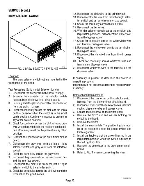
FIG. 3 BREW SELECTOR SWITCHES<br />
Location:<br />
The brew selector switch(es) are mounted in the<br />
front panel of the hood.<br />
Test Procedure (Early model Selector Switch):<br />
1. Disconnect the brewer from the power supply.<br />
2. Separate the connector on the selector switch<br />
harness from the brew timer circuit board.<br />
3. Carefully slide the plastic cover off of the connector<br />
from the switch harness.<br />
4. Check for continuity across the pink and tan wires<br />
on the connector when the switch is in the small<br />
batch position. Continuity must not be present in<br />
any other switch position.<br />
5. Check for continuity across the pink wire and gray<br />
wire when the switch is in the medium batch position.<br />
Continuity must not be present in any other<br />
position.<br />
6. Reattach the connector to the brew timer circuit<br />
board.<br />
7. Disconnect the gray wire from the left or right<br />
selector switch and gray wire from the interface<br />
socket.<br />
8. Check for continuity across the gray wires.<br />
9. Reconnect the gray wires from the selector switches<br />
and the interface socket.<br />
10. Disconnect the pink wire from the left or right<br />
selector switch to the grinder switch.<br />
11. Check for continuity across the pink wire and the<br />
terminal on the grind switch.<br />
1⁄2 gal<br />
1 1⁄2 gal<br />
1 gal<br />
1⁄2 gal<br />
1 1⁄2 gal<br />
1 gal<br />
P775<br />
Page 12<br />
12. Reconnect the pink wire to the grind switch.<br />
13. Disconnect the tan wire from the left or right selector<br />
switch and tan wire from interface socket.<br />
14. Check for continuity across the tan wires.<br />
15. Reconnect the tan wires.<br />
16. With the selector switch set at the medium and<br />
large batch positions, disconnect the white/violet<br />
from the bypass valve.<br />
17. Check for continuity across the white/violet wire<br />
and terminal on bypass valve.<br />
18. Reconnect the white/violet wire to the terminal on<br />
the bypass valve.<br />
19. Disconnect the white/red wire from the dispense<br />
valve.<br />
20. Check for continuity across white/red wire and<br />
terminal on dispense valve.<br />
21. Reconnect white/red wire to the terminal on the<br />
dispense valve.<br />
If continuity is present as described the switch is<br />
operating properly.<br />
If continuity is not present as described replace switch<br />
assembly.<br />
Removal and Replacement:<br />
1. Disconnect the connector on the selector switch<br />
harness from the brewer timer circuit board.<br />
2. Disconnect wires from the selector switch, interface<br />
socket, dispense valve and bypass valve.<br />
3. Loosen the set screw on the switch knob.<br />
4. Remove the 9/16" nut and washer holding the<br />
switch to the hood.<br />
5. Remove the switch.<br />
6. Install the new switch. The positioning tab must<br />
be in the hole in the hood for proper switch and<br />
knob alignment.<br />
7. Install the knob so that the arrow lines up in the<br />
large batch position when the switch is turned to<br />
the full right position.<br />
8. Reattach the connector to the brew timer circuit<br />
board.<br />
9. Refer to Fig. 4 when reconnecting the wires.<br />
41976 031709