DUAL ®& DUAL ® SH SINGLE ®& SINGLE ® SH - Expert-CM
DUAL ®& DUAL ® SH SINGLE ®& SINGLE ® SH - Expert-CM
DUAL ®& DUAL ® SH SINGLE ®& SINGLE ® SH - Expert-CM

Create successful ePaper yourself
Turn your PDF publications into a flip-book with our unique Google optimized e-Paper software.
SERVICE (cont.)<br />
CONTACTOR ASSEMBLY (cont.)<br />
If continuity is not present as described, replace the<br />
contactor.<br />
Test Procedures :<br />
Electronic Control (Brewers w/Recovery Booster)<br />
1. Disconnect the brewer from the power source.<br />
2. Disconnect the gray wire from the black wire on<br />
the rear of the contactor coil and white /brown wire<br />
from the black wire on the front of the contactor<br />
coil.<br />
3. With a voltmeter, check the voltage across the<br />
gray wire and white/brown wire with both "ON/<br />
OFF" switches in the "ON" position. Connect the<br />
brewer to the power source and press both start<br />
switches. The indication must be:<br />
a.) 120 volts ac for three wire 120/208 volt models<br />
and three wire 120/240 volt models.<br />
b.) 200 to 240 volts ac for two wire 200 or 240<br />
volt models.<br />
4. Disconnect the brewer from the power source.<br />
If voltage is present as described, proceed to #5.<br />
If voltage is not present as described, refer to the Wiring<br />
Diagrams and check brewer wiring harness.<br />
5. Disconnect the blue and red wires from the contactor<br />
terminals. Check for continuity across the<br />
terminals of the contactor by manually closing the<br />
contacts. Continuity must not be present when the<br />
contact is released.<br />
If continuity is present as described, reconnect the<br />
blue and red wires to the contactor terminals. Connect<br />
one black lead from the contactor coil to the gray<br />
wire and the white/brown wire to the remaining black<br />
lead of the contactor coil. The contactor is operating<br />
properly.<br />
If continuity is not present as described, replace the<br />
contactor.<br />
Removal and Replacement:<br />
1. Remove all wires from the contactor.<br />
2. Remove the two #10-32 slotted head screw securing<br />
contactor to the inside of the hood.<br />
Page 16<br />
3. Securely install the new contactor inside the<br />
hood.<br />
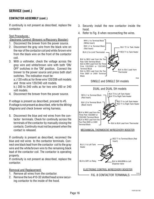
4. Refer to Fig. 8 when reconnecting the wires.<br />
WHI L1 to Terminal Block<br />
(White Insert)<br />
RED L1 to Terminal Block<br />
(Red Insert)<br />
BLK L2 to Limit Thermostat<br />
BLK to WHI Lead from the Two<br />
Pole 120V Terminal Block<br />
BLK to WHI Lead from the Three<br />
Pole 120/208V or 120/240V<br />
Terminal Block<br />
BLK to RED Lead from the Two<br />
Pole 200V or 240V Terminal<br />
Block<br />
RED L1 to Terminal Block<br />
(Red Insert)<br />
BLK L2 to Terminal Block<br />
(Black Insert)<br />
BLK to WHI Lead from the<br />
Three Pole 120/208V or<br />
120/240V Terminal Block<br />
BLK to RED Lead from the<br />
Two Pole 200V or 240V<br />
Terminal Block<br />
BLK T2 to Left Tank Heater<br />
BLK T2 to Right Tank Heater<br />
RED T1 to Left Tank Heater<br />
RED T1 to Right Tank Heater<br />
BLK to BLK Lead from Thermostat<br />
MECHANICAL THERMOSTAT W/RECOVERY BOOSTER<br />
BLU L1 to Left Tank<br />
Heater<br />
<strong>SINGLE</strong> and <strong>SINGLE</strong> <strong>SH</strong> models<br />
<strong>DUAL</strong> and <strong>DUAL</strong> <strong>SH</strong> models<br />
RED T1 to Terminal Block (Red<br />
Insert)<br />
BLK to GRY on Relay BLK to WHI/BRN to Left<br />
Dispense Valve<br />
ELECTRONIC CONTROL W/RECOVERY BOOSTER<br />
FIG. 8 CONTACTOR TERMINALS<br />
BLK T2 to Tank Heater<br />
RED T1 to Tank Heater<br />
BLK to BLK Lead from<br />
Thermostat<br />
P828<br />
P778<br />
41976 031709