DUAL ®& DUAL ® SH SINGLE ®& SINGLE ® SH - Expert-CM
DUAL ®& DUAL ® SH SINGLE ®& SINGLE ® SH - Expert-CM
DUAL ®& DUAL ® SH SINGLE ®& SINGLE ® SH - Expert-CM

You also want an ePaper? Increase the reach of your titles
YUMPU automatically turns print PDFs into web optimized ePapers that Google loves.
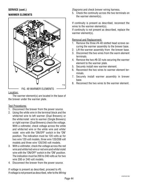
SERVICE (cont.)<br />
WARMER ELEMENTS<br />
.<br />
MINUTES<br />
BUNN-O-MATIC<br />
P/N 2620- 120 VAC<br />
.<br />
MINUTES<br />
BUNN-O-MATIC<br />
P/N 2620- 120 VAC<br />
1⁄2 gal<br />
1 1⁄2 gal<br />
1 gal<br />
READY SELECTOR<br />
ON / WARMER START<br />
CAUTIO N: WAR M E RS AND S URF ACES AR E H OT<br />
! CAUTION HOT WATER<br />
1 1⁄2 gal<br />
1 gal<br />
START ON / WARMER SELECTOR READY<br />
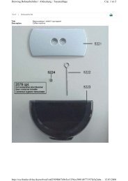
FIG. 49 WARMER ELEMENTS<br />
Location:<br />
The warmer element(s) are located in the base of<br />
the brewer under the warmer plate.<br />
Test Procedures:<br />
1. Disconnect the brewer from the power source.<br />
2. Using the white wire in the terminal block and the<br />
white/red wire to left warmer (Dual Brewers) or<br />
the white/violet wire to warmer (Single Brewers)<br />
or right warmer (Dual Brewers) check the voltage.<br />
With a voltmeter, check voltage across the white<br />
and white/red wire or the white wire and white/<br />
violet wire with the "ON/OFF" switch in the "ON"<br />
position. The indication must be 120 volts ac for<br />
two wire 120 volt models, three wire 120/208 volt<br />
models and three wire 120/240 volt models.<br />
3. With a voltmeter, check the voltage across the red<br />
wire and white/red wire or red wire and white/violet<br />
wire with the "ON/OFF" switch in the "ON" position.<br />
The indication must be 200 to 240 volts ac for two<br />
wire 200 or 240 volt models.<br />
4. Disconnect the brewer from the power source.<br />
If voltage is present as described, proceed to #5.<br />
If voltage is not present as described, refer to the Wiring<br />
1⁄2 gal<br />
P796<br />
Page 44<br />
Diagrams and check brewer wiring harness.<br />
5. Check the continuity across the two terminals on<br />
the warmer element(s).<br />
If continuity is present as described, reconnect the<br />
wires to the warmer element(s).<br />
If continuity is not present as described, replace the<br />
warmer element(s).<br />
Removal and Replacement:<br />
1. Remove the three #4-40 slotted head screws securing<br />
the warmer assembly to the brewer base.<br />
2. Lift the warmer assembly from the brewer base.<br />
3. Disconnect the two wires from the warm element<br />
terminals.<br />
4. Remove the two #8-32 nuts securing the warmer<br />
element to the warmer plate.<br />
5. Securely install new warmer element.<br />
6. Reconnect the two wires to warmer element terminals.<br />
7. Securely install warmer assembly in brewer<br />
base.<br />
8. Reconnect the two wires to the warmer element.<br />
41976 031709