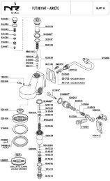
DUAL ®& DUAL ® SH SINGLE ®& SINGLE ® SH - Expert-CM
DUAL ®& DUAL ® SH SINGLE ®& SINGLE ® SH - Expert-CM
DUAL ®& DUAL ® SH SINGLE ®& SINGLE ® SH - Expert-CM

Create successful ePaper yourself
Turn your PDF publications into a flip-book with our unique Google optimized e-Paper software.
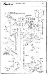
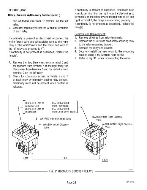
SERVICE (cont.)<br />
Relay (Brewers W/Recovery Booster) (cont.)<br />
and white/red wire from "B" terminal on the left<br />
relay.<br />
6. Check for continuity across the "A" and "B" terminals<br />
of each relay.<br />
If continuity is present as described, reconnect the<br />
white /green wire and white/violet wire to the right<br />
relay or the white/brown and the white /red wire to<br />
the left relay and proceed to #7.<br />
If continuity is not present as described, replace the<br />
relay(s).<br />
7. Remove the two blue wires from terminal 5 and<br />
the red wire from terminal 7 on the right relay, the<br />
black wires from terminal 5 and the red wire from<br />
terminal 7 on the left relay.<br />
8. Check for continuity across terminals 5 and 7<br />
of each relay by manually closing relay contact.<br />
Continuity must not be present when contact is<br />
released.<br />
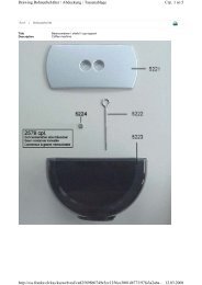
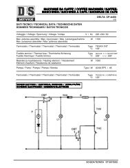
5<br />
BLK to BLK Lead on<br />
Contactor Coil<br />
BLK to BLK Lead on<br />
Thermostat<br />
LEFT<br />
7<br />
B<br />
BLU to BLU Lead<br />
from Thermostat<br />
BLU to BLU Lead<br />
from Liquid Level Board<br />
WHI/RED to Left Dispense Valve<br />
A WHI/BRN to Left Dispense<br />
Valve<br />
A<br />
RED<br />
BREWERS W/RECOVERY BOOSTER<br />
FIG. 31 RECOVERY BOOSTER RELAYS<br />
Page 28<br />
If continuity is present as described, reconnect blue<br />
wires to terminal 5 on the right relay, the black wires to<br />
terminal 5 on the left relay and the red wire to left and<br />
right terminal 7, the relays are operating properly.<br />
If continuity is not present as described, replace the<br />
relay(s).<br />
Removal and Replacement:<br />
1. Remove all wires from relay terminals.<br />
2. Remove the #6-32 truss head screw securing relay<br />
to the relay mounting bracket.<br />
3. Remove the relay and discard.<br />
4. Securely install the new relay to the mounting<br />
bracket using a #6-32 truss head screw.<br />
5. Refer to Fig. 31 when reconnecting the wires.<br />
5<br />
B<br />
WHI/VIO to Right Dispense<br />
Valve<br />
7<br />
WHI/GRN to Right Dispense<br />
Valve<br />
RIGHT<br />
P1378<br />
41976 031709