DUAL ®& DUAL ® SH SINGLE ®& SINGLE ® SH - Expert-CM
DUAL ®& DUAL ® SH SINGLE ®& SINGLE ® SH - Expert-CM
DUAL ®& DUAL ® SH SINGLE ®& SINGLE ® SH - Expert-CM

Create successful ePaper yourself
Turn your PDF publications into a flip-book with our unique Google optimized e-Paper software.
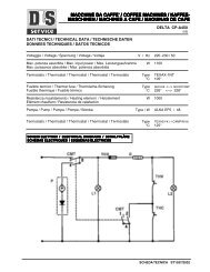
SERVICE (cont.)<br />
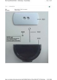
TIMERS (Early Models)<br />
.<br />
MINUTES<br />
BUNN-O-MATIC<br />
P/N 2620- 120 VAC<br />
.<br />
MINUTES<br />
BUNN-O-MATIC<br />
P/N 2620- 120 VAC<br />
READY SELECTOR<br />
ON / WARMER START<br />
Location:<br />
The timers are located inside the left front of the<br />
brewer on the upper part of the component bracket.<br />
Test Procedures:<br />
1. Disconnect the brewer from the power source.<br />
2. Disconnect the wires from the timer terminals TL3,<br />
TL4 and TL5 and rotate the dial(s) fully counterclockwise.<br />
3. With a voltmeter, check the voltage across terminals<br />
TL1 and TL2 when the "ON/OFF" switch is in the<br />
"ON" position. Connect the brewer to the power<br />
source. The indication must be:<br />
a.) 120 volts ac for two wire 120 volt models, three<br />
wire 120/208 volt models and three wire 120/240<br />
volt models.<br />
b.) 200 to 240 volts ac for two wire 200 or 240<br />
volt models.<br />
4. Disconnect the brewer from the power source.<br />
If voltage is present as described, proceed to #5.<br />
If voltage is not present as described, refer to the Wiring<br />
Diagrams and check brewer wiring harness.<br />
1 1⁄2 gal<br />
1 gal<br />
EARLY MODELS<br />
FIG. 42 TIMERS<br />
1⁄2 gal<br />
CAUTION : WARMERS AN D SURFAC ES ARE HOT<br />
! CAUTION HOT WATER<br />
1 1⁄2 gal<br />
1 gal<br />
START ON / WARMER SELECTOR READY<br />
1⁄2 gal<br />
P796<br />
Page 37<br />
NOTE: ECA MODELS ONLY - Brewer must be at operating<br />
temperature to perform step 5 or brew-lock<br />
must be bypassed. To bypass brew-lock on <strong>DUAL</strong><br />
models, disconnect white/orange wire and brown/<br />
black wire for right timer or orange wire and red/black<br />
wire for left timer from brew-lock of ECA and connect<br />
the harness leads together. To bypass brew-lock on<br />
<strong>SINGLE</strong> models, disconnect white/yellow and orange<br />
wires from brew-lock of ECA and connect the harness<br />
leads together.<br />
5. With the start switch pressed, check for continuity<br />
across the wires disconnected from TL3 and TL5 of<br />
the timer. <strong>DUAL</strong> models will be white/orange and<br />
white/yellow wires for right timer or the orange and<br />
yellow wires for left timer. <strong>SINGLE</strong> models will be<br />
white/orange and white yellow wires for electro/<br />
mechanical brewers and white/yellow and yellow<br />
wires on electronic brewers.<br />
If continuity is present as described, reconnect the wires<br />
to terminals TL3, TL4 and TL5 of the timer board and<br />
brew-lock wires if necessary, and proceed to #6.<br />
6. Check the voltage across terminals TL1 and TL4<br />
with a voltmeter when the "ON/OFF" switch is in<br />
the "ON" position. Connect the brewer to the power<br />
source and press the start switch. The indication<br />
must be:<br />
a.) 120 volts ac for two wire 120 volt models, three<br />
wire 120/208 volt models and three wire 120/240<br />
volt models for approximately 1 minute for 1-1/2<br />
gallon batch.<br />
b.) 200 to 240 volts ac for two wire 200 or 240<br />
volt models for approximately 1 minute for 1-1/2<br />
gallon batch.<br />
7. Select a 1 gallon batch and repeat #6. The indication<br />
should remain for approximately 40 seconds.<br />
8. Select a 1/2 gallon batch and repeat #6. The indication<br />
should remain approximately 20 seconds.<br />
Removal and Replacement:<br />
1. Remove all wires from the timer.<br />
2. Remove the four #6-32 slotted head screws holding<br />
circuit board and dial plate on to the component<br />
mounting bracket.<br />
3. Remove circuit board, nylon spacers and dial<br />
plate.<br />
41976 031709