DUAL ®& DUAL ® SH SINGLE ®& SINGLE ® SH - Expert-CM
DUAL ®& DUAL ® SH SINGLE ®& SINGLE ® SH - Expert-CM
DUAL ®& DUAL ® SH SINGLE ®& SINGLE ® SH - Expert-CM

Create successful ePaper yourself
Turn your PDF publications into a flip-book with our unique Google optimized e-Paper software.
SERVICE (cont.)<br />
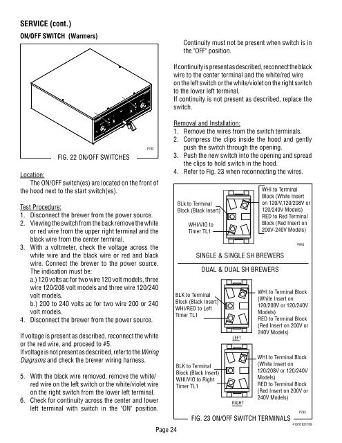
ON/OFF SWITCH (Warmers)<br />
READY SELECTOR<br />
ON / WARMER START<br />
START ON / WARMER SELECTOR READY<br />
Location:<br />
The ON/OFF switch(es) are located on the front of<br />
the hood next to the start switch(es).<br />
Test Procedure:<br />
1. Disconnect the brewer from the power source.<br />
2. Viewing the switch from the back remove the white<br />
or red wire from the upper right terminal and the<br />
black wire from the center terminal.<br />
3. With a voltmeter, check the voltage across the<br />
white wire and the black wire or red and black<br />
wire. Connect the brewer to the power source.<br />
The indication must be:<br />
a.) 120 volts ac for two wire 120 volt models, three<br />
wire 120/208 volt models and three wire 120/240<br />
volt models.<br />
b.) 200 to 240 volts ac for two wire 200 or 240<br />
volt models.<br />
4. Disconnect the brewer from the power source.<br />
If voltage is present as described, reconnect the white<br />
or the red wire, and proceed to #5.<br />
If voltage is not present as described, refer to the Wiring<br />
Diagrams and check the brewer wiring harness.<br />
5. With the black wire removed, remove the white/<br />
red wire on the left switch or the white/violet wire<br />
on the right switch from the lower left terminal.<br />
6. Check for continuity across the center and lower<br />
left terminal with switch in the "ON" position.<br />
1⁄2 gal 1 gal 1 1⁄2 gal<br />
FIG. 22 ON/OFF SWITCHES<br />
1⁄2 gal 1 gal 1 1⁄2 gal<br />
P792<br />
Page 24<br />
Continuity must not be present when switch is in<br />
the "OFF" position.<br />
If continuity is present as described, reconnect the black<br />
wire to the center terminal and the white/red wire<br />
on the left switch or the white/violet on the right switch<br />
to the lower left terminal.<br />
If continuity is not present as described, replace the<br />
switch.<br />
Removal and Installation:<br />
1. Remove the wires from the switch terminals.<br />
2. Compress the clips inside the hood and gently<br />
push the switch through the opening.<br />
3. Push the new switch into the opening and spread<br />
the clips to hold switch in the hood.<br />
4. Refer to Fig. 23 when reconnecting the wires.<br />
BLk to Terminal<br />
Block (Black Insert)<br />
WHI/VIO to<br />
Timer TL1<br />
<strong>SINGLE</strong> & <strong>SINGLE</strong> <strong>SH</strong> BREWERS<br />
BLK to Terminal<br />
Block (Black Insert)<br />
WHI/RED to Left<br />
Timer TL1<br />
BLK to Terminal<br />
Block (Black Insert)<br />
WHI/VIO to Right<br />
Timer TL1<br />
<strong>DUAL</strong> & <strong>DUAL</strong> <strong>SH</strong> BREWERS<br />
LEFT<br />
RIGHT<br />
WHI to Terminal<br />
Block (White Insert<br />
on 120/V,120/208V or<br />
120/240V Models)<br />
RED to Red Terminal<br />
Block (Red Insert on<br />
200V-240V Models)<br />
WHI to Terminal Block<br />
(White Insert on<br />
120/208V or 120/240V<br />
Models)<br />
RED to Terminal Block<br />
(Red Insert on 200V or<br />
240V Models)<br />
WHI to Terminal Block<br />
(White Insert on<br />
120/208V or 120/240V<br />
Models)<br />
RED to Terminal Block<br />
(Red Insert on 200V or<br />
240V Models)<br />
FIG. 23 ON/OFF SWITCH TERMINALS<br />
P843<br />
P793<br />
41976 031709