DUAL ®& DUAL ® SH SINGLE ®& SINGLE ® SH - Expert-CM
DUAL ®& DUAL ® SH SINGLE ®& SINGLE ® SH - Expert-CM
DUAL ®& DUAL ® SH SINGLE ®& SINGLE ® SH - Expert-CM

Create successful ePaper yourself
Turn your PDF publications into a flip-book with our unique Google optimized e-Paper software.
SERVICE (cont.)<br />
OVERFLOW PROTECTION SWITCH<br />
TL5<br />
TL4<br />
TL3<br />
TL2<br />
TL1<br />
SET<br />
LOCK<br />
SET LOCK<br />
J2<br />
J1<br />
TL5<br />
TL4<br />
TL3<br />
TL2<br />
TL1<br />
SET<br />
LOCK<br />
SET LOCK<br />
.500 gpm FLOW<br />
BUNN<br />
90 psig max operating pressure<br />
Strainer/Flow Control # 22300.0750<br />
(Repl. Flow Washer #20526.0750)<br />
(Repl. Screen #23721.0000)<br />
J2<br />
J1<br />
READY SELECTOR<br />
ON / WARMER START<br />
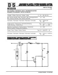
FIG. 24 OVERFLOW PROTEC-<br />
TION SWITCH<br />
START ON / WARMER SELECTOR READY<br />
Location:<br />
The overflow protection switch is located inside the<br />
hood on the tank inside the copper overflow cup.<br />
To test the overflow protection switch, access will<br />
also be needed to the level control board or electronic<br />
control assembly and terminal block.<br />
Test Procedure:<br />
1. Disconnect the brewer from the power source.<br />
2. Remove the wire nuts connecting the red wires<br />
from the overflow protection switch to the black<br />
wire from the terminal block and blue wire from<br />
the thermostat or the black and red wires from the<br />
electronic control assembly.<br />
3. Check for continuity across the overflow protection<br />
switch red wires only until the plastic float is<br />
raised and check that continuity returns when the<br />
plastic float is again lowered.<br />
If continuity is present as described, reconnect the<br />
red wires to the blue wire from the thermostat and<br />
Liquid Level Control and the black wire from terminal<br />
block or black and red wires from electronic control<br />
assembly.<br />
If continuity is not present as described, replace the<br />
1⁄2 gal<br />
1 1⁄2 gal<br />
1 gal<br />
1⁄2 gal<br />
1 1⁄2 gal<br />
1 gal<br />
P2194<br />
Page 25<br />
overflow protection switch.<br />
Removal and Replacement:<br />
1. Disconnect the red leads from the overflow protection<br />
switch from the blue wire from the thermostat<br />
and the black wire from the terminal block or black<br />
and red wires from electronic control assembly.<br />
2. Remove the nut beneath the copper overflow<br />
cup.<br />
3. Remove the entire switch assembly from the<br />
cup.<br />
4. Place the new switch assembly into the cup, wires<br />
first. Make sure that the gasket is in place around<br />
the threaded switch stem.<br />
NOTE - The magnets must be at the top of float and<br />
there must be NO adjusting washers installed for the<br />
overflow protection switch to operate properly.<br />
5. Install the nut beneath the copper overflow cup.<br />
Be sure not to overtighten.<br />
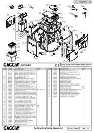
6. Refer to Fig. 25 when reconnecting wires.<br />
RED to BLK Wire<br />
form Terminal Block<br />
or<br />
RED to BLK Lead<br />
from J3-12<br />
RED to BLU Lead<br />
from Thermostat &<br />
Liquid Level Control<br />
or<br />
RED to RED Lead<br />
from J3-11<br />
FIG. 25 OVERFLOW PROTECTION<br />
SWITCH TERMINALS<br />
P795<br />
41976 031709