DUAL ®& DUAL ® SH SINGLE ®& SINGLE ® SH - Expert-CM
DUAL ®& DUAL ® SH SINGLE ®& SINGLE ® SH - Expert-CM
DUAL ®& DUAL ® SH SINGLE ®& SINGLE ® SH - Expert-CM

You also want an ePaper? Increase the reach of your titles
YUMPU automatically turns print PDFs into web optimized ePapers that Google loves.
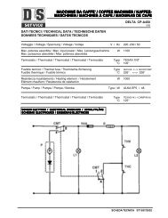
SERVICE (cont.)<br />
LEVEL CONTROL BOARD AND LEVEL PROBE (cont.)<br />
b.) 200 to 240 volts ac for two wire 200 or 240 volt<br />
models after a delay of approximately 1 second.<br />
15. Move the probe's flat end to the brewer housing.<br />
The indication must be 0.<br />
16. Move the probe's flat end away from the brewer<br />
housing. The indication should again be:<br />
a.) 120 volts ac for two wire 120 volt models, three<br />
wire 120/208 volt models and three wire 120/240<br />
volt models.<br />
b.) 200 to 240 volts ac for two wire 200 or 240<br />
volt models.<br />
17. Disconnect the brewer from the power source.<br />
If voltage is present as described, reinstall the probe,<br />
the level control board and level probe are operating<br />
properly.<br />
If voltage is not present as described, check the pink<br />
probe wire.<br />
Removal and Replacement:<br />
1. Remove all wires from the level control board.<br />
2. Remove two #8-32 slotted head screws holding<br />
level control board to component bracket.<br />
3. Install the new level control board to the component<br />
bracket. Make certain that the lockwashers are<br />
between the level control board and the component<br />
bracket.<br />
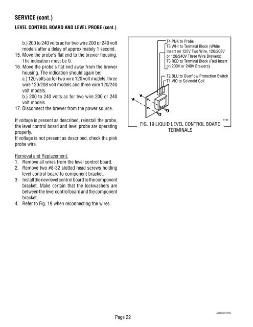
4. Refer to Fig. 19 when reconnecting the wires.<br />
Page 22<br />
T4 PNK to Probe<br />
T3 WHI to Terminal Block (White<br />
Insert on 120V Two Wire, 120/208V<br />
or 120/240V Three Wire Brewers)<br />
T3 RED to Terminal Block (Red Insert<br />
on 200V or 240V Brewers)<br />
T2 BLU to Overflow Protection Switch<br />
T1 VIO to Solenoid Coil<br />
FIG. 19 LIQUID LEVEL CONTROL BOARD<br />
TERMINALS<br />
P789<br />
41976 031709