
You also want an ePaper? Increase the reach of your titles
YUMPU automatically turns print PDFs into web optimized ePapers that Google loves.
a<br />
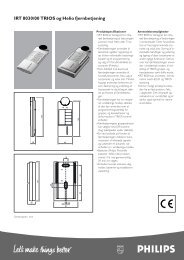
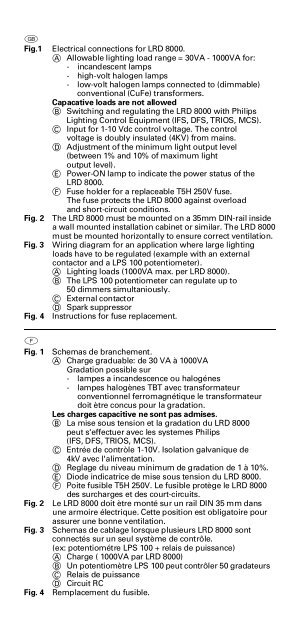
F i g . 1 Electrical connections for <strong>LRD</strong> <strong>8000</strong>.<br />
A Allowable lighting load range = 30VA - 1000VA for:<br />
- incandescent lamps<br />
- high-volt halogen lamps<br />
- low-volt halogen lamps connected to (dimmable)<br />
conventional (CuFe) transformers.<br />
Capacative loads are not allowed<br />
B Switching and regulating the <strong>LRD</strong> <strong>8000</strong> with <strong>Philips</strong><br />
Lighting Control Equipment (IFS, DFS, TRIOS, MCS).<br />
C Input for 1-10 Vdc control voltage. The control<br />
voltage is doubly insulated (4KV) from mains.<br />
D Adjustment of the minimum light output level<br />
(between 1% and 10% of maximum light<br />
output level).<br />
E Power-ON lamp to indicate the power status of the<br />
<strong>LRD</strong> <strong>8000</strong>.<br />
F Fuse holder for a replaceable T5H 250V fuse.<br />
The fuse protects the <strong>LRD</strong> <strong>8000</strong> against overload<br />
and short-circuit conditions.<br />
Fig. 2 The <strong>LRD</strong> <strong>8000</strong> must be mounted on a 35mm DIN-rail inside<br />
a wall mounted installation cabinet or similar. The <strong>LRD</strong> <strong>8000</strong><br />
must be mounted horizontally to ensure correct ventilation.<br />
Fig. 3 Wiring diagram for an application where large lighting<br />
loads have to be regulated (example with an external<br />
contactor and a LPS 100 potentiometer).<br />
A Lighting loads (1000VA max. per <strong>LRD</strong> <strong>8000</strong>).<br />
B The LPS 100 potentiometer can regulate up to<br />
50 dimmers simultaniously.<br />
C External contactor<br />
D Spark suppressor<br />
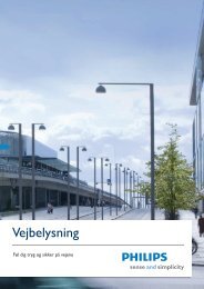
Fig. 4 Instructions for fuse replacement.<br />
b<br />
Fig. 1<br />
Fig. 2<br />
Fig. 3<br />
Schemas de branchement.<br />
A Charge graduable: de 30 VA à 1000VA<br />
Gradation possible sur<br />
- lampes a incandescence ou halogénes<br />
- lampes halogènes TBT avec transformateur<br />
conventionnel ferromagnétique le transformateur<br />
doit ètre concus pour la gradation.<br />
Les charges capacitive ne sont pas admises.<br />
B La mise sous tension et la gradation du <strong>LRD</strong> <strong>8000</strong><br />
peut s'effectuer avec les systemes <strong>Philips</strong><br />
(IFS, DFS, TRIOS, MCS).<br />
C Entrée de contròle 1-10V. Isolation galvanique de<br />
4kV avec l'alimentation.<br />
D Reglage du niveau minimum de gradation de 1 à 10%.<br />
E Diode indicatrice de mise sous tension du <strong>LRD</strong> <strong>8000</strong>.<br />
F Poite fusible T5H 250V. Le fusible protège le <strong>LRD</strong> <strong>8000</strong><br />
des surcharges et des court-circuits.<br />
Le <strong>LRD</strong> <strong>8000</strong> doit ètre monté sur un rail DIN 35 mm dans<br />
une armoire électrique. Cette position est obligatoire pour<br />
assurer une bonne ventilation.<br />
Schemas de cablage lorsque plusieurs <strong>LRD</strong> <strong>8000</strong> sont<br />
connectés sur un seul système de contrôle.<br />
(ex: potentiométre LPS 100 + relais de puissance)<br />
A Charge ( 1000VA par <strong>LRD</strong> <strong>8000</strong>)<br />
B Un potentiomètre LPS 100 peut contrôler 50 gradateurs<br />
C Relais de puissance<br />
D Circuit RC<br />
Fig. 4 Remplacement du fusible.